

Page 1
INSTALLATION INSTRUCTIONS FOR YOUR NEW
24"BUILT-INOVEN
Before you begin - Read these instructions completely and carefully.
IMPORTANT - Save these instructions for local inspector's use.
IMPORTANT - OBSERVE ALL GOVERNING CODES AND ORDINANCES.
Note to Installer - Be sure to leave these instructions with the Consumer.
Note to Consumer - Keep these instructions with your Use and Care Book for future
reference.
Be sure your oven is installed properly by a qualified
installer or service technician.
• Be sure the oven is securely installed in a cabinet
that is firmly attached to the house structure.
Weight on the oven door could cause the oven to
tip resulting in serious personal injury or death.
Never allow anyone to climb, sit, lean, stand, or
hang on the oven door.
• The wall coverings, countertop and cabinets
around the oven should be able to withstand the
heat (up to 200°F) generated by the oven.
1/8" Drill Bit
Electric or Hand Drill
Flat Blade screwdriver
Cabinet space must be provided to enclose the
recessed partofyour built-in oven. SINGLE OVEN
Ruler
Ha nd or saber saw
Pencil
IN STALLATI ON i See Figure I for all necessary
dimensions. DOU BLE OVEN INSTALLATION
i See Figure 2 for all necessa_j dimensions. It is
best to make a template to insure accurate cutting.
Place the bottom of the template on a level base line,
above the floor. See dimension E in Figure I (Single
Oven) or Figure 2 (Double Oven).
It is important that the oven be installed at or above
the minimum height specified. The unit has been
tested and approved, in accordance with safety
standards, at this height.
Pub. No, 31-10241
INT224-14
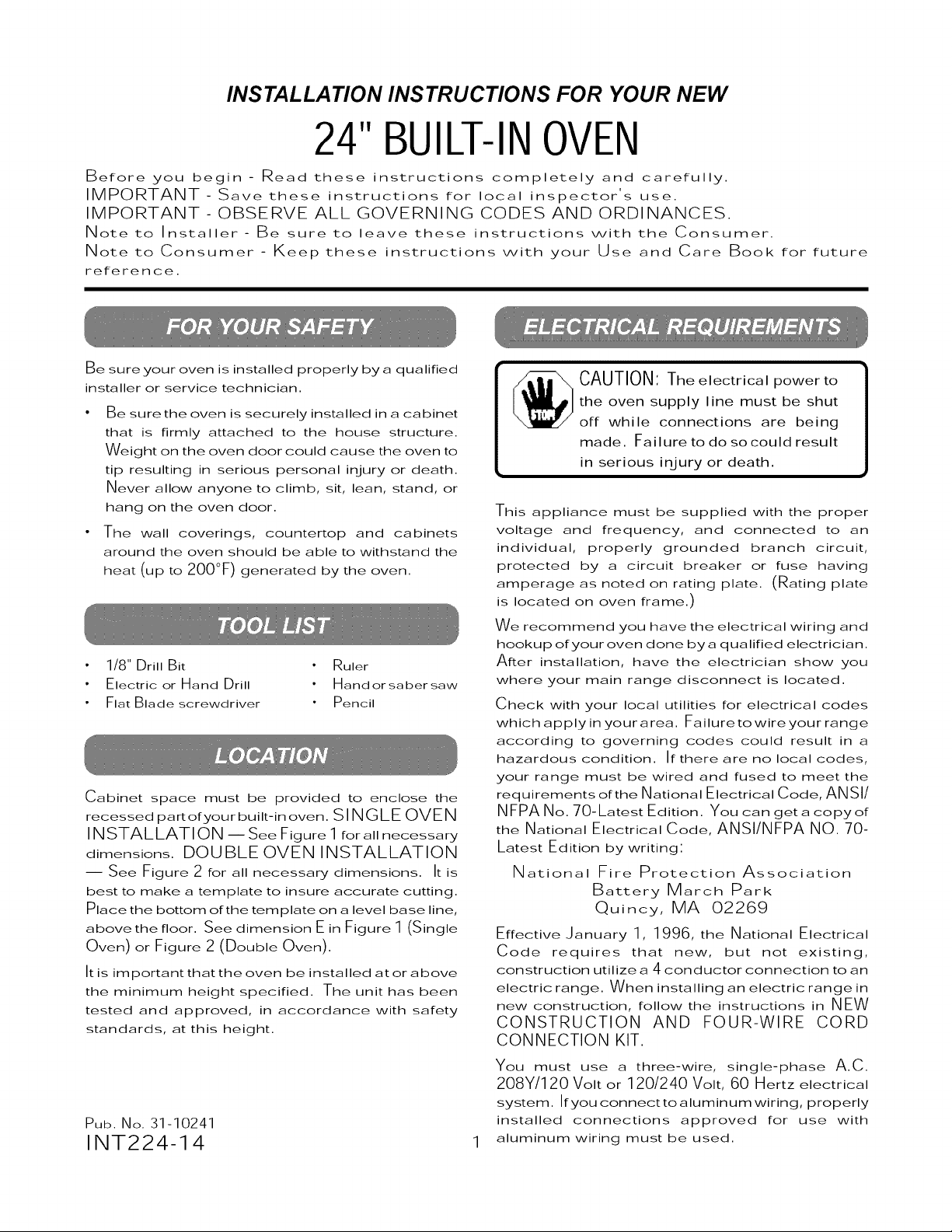
CAUTION: The electrical power to
the oven supply line must be shut
off while connections are being
made. Failure to do so could result
in serious injury or death.
This appliance must be supplied with the proper
voltage and frequency, and connected to an
individual, properly grounded branch circuit,
protected by a circuit breaker or fuse having
amperage as noted on rating plate. (Rating plate
is located on oven frame.)
We recommend you have the electrical wiring and
hookup of your oven done by a qualified electrician.
After installation, have the electrician show you
where your main range disconnect is located.
Check with your local utilities for electrical codes
which apply in yourarea. Failuretowireyour range
according to governing codes could result in a
hazardous condition. If there are no local codes,
your range must be wired and fused to meet the
requirements of the National Electrical Code, ANSI/
NFPA No. 70-Latest Edition. You can geta copyof
the National Electrical Code, ANSI/NFPA NO. 70-
Latest Edition by writing:
National Fire Protection Association
Battery March Park
Quincy, MA 02269
Effective January 1, 1996, the National Electrical
Code requires that new, but not existing,
construction utilize a 4 conductor connection to an
electric range. When installing an electric range in
new construction, follow the instructions in NEW
CONSTRUCTION AND FOUR-WIRE CORD
CONNECTION KIT.
You must use a three-wire, single-phase A.C.
208Y/120 Volt or 120/240 Volt, 60 Hertz electrical
system. If you connect to aluminum wiring, properly
installed connections approved for use with
aluminum wiring must be used.
Page 2
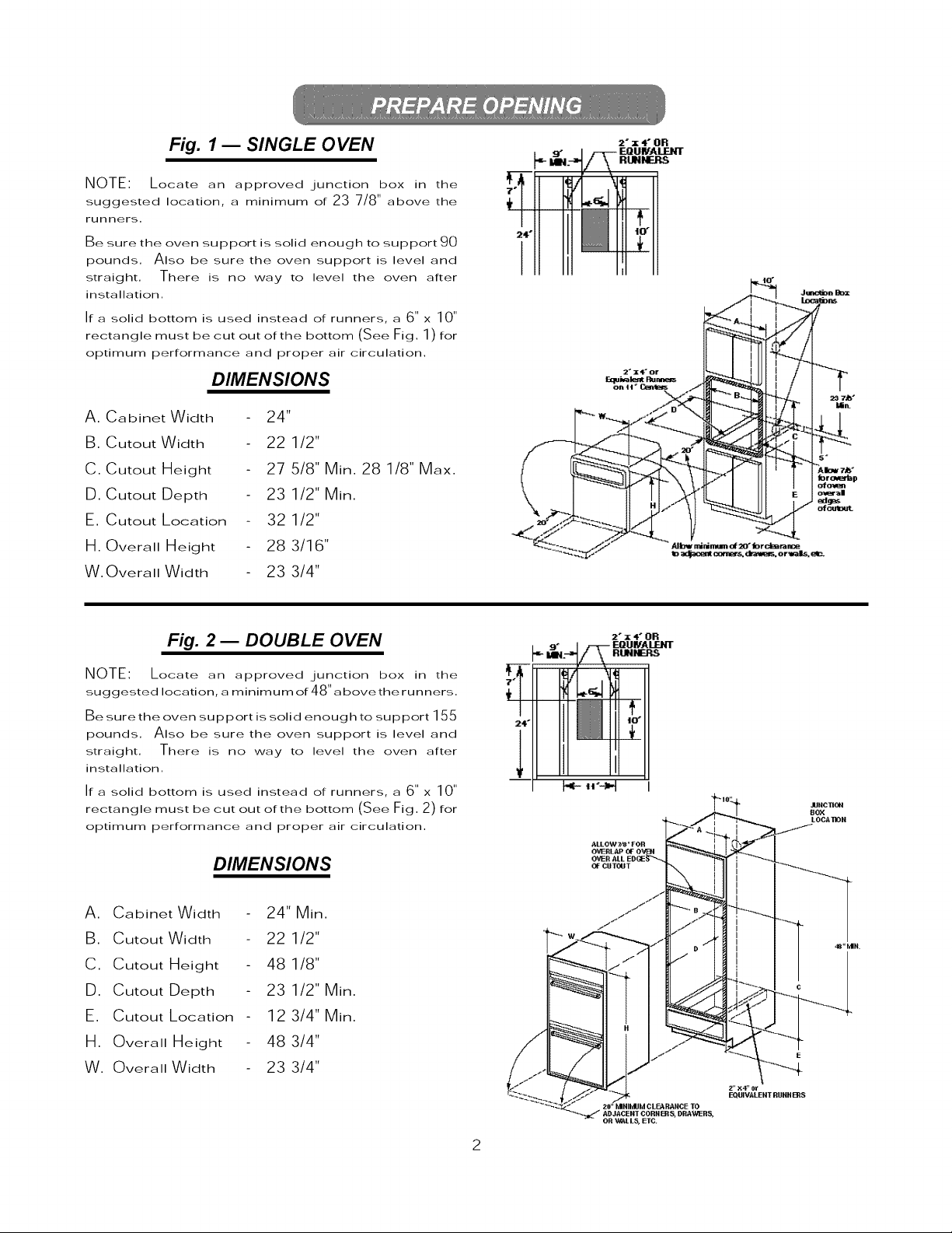
Fig. I m SINGLE 0 VEN
NOTE' Locate an approved junction box in the
suggested location, a minimum of 23 7/8" above the
runners,
Be sure the oven support is solid enough to support 90
pounds. Also be sure the oven support is level and
straight. There is no way to level the oven after
installation.
If a solid bottom is used instead of runners, a 6" x 10"
rectangle must be cut out of the bottom (See Fig. 1 ) for
optimum performance and proper air circulation.
DIMENSIONS
2"x4" OR
A. Cabinet Width
B. Cutout Width
C. Cutout Height
U. Cutout Depth
E. Cutout Location
m. Overall Height
W. Overall Width
24"
22 1/2"
27 5/8" Min. 28 1/8" Max.
23 1/2" Min.
32 1/2"
28 3/16"
23 3/4"
Fig. 2 _ DOUBLE OVEN
NOTE: Locate an approved junction box in the
suggested location, a minimum of 48"above the runners.
Be sure the oven support is solid enough to support 155
pounds. Also be sure the oven support is level and
straight. There is no way to level the oven after
installation.
If a solid bottom is used instead of runners, a 6" x 10"
rectangle must be cut out of the bottom (See Fig. 2) for
optimum performance and proper air circulation.
DIMENSIONS
/ 9" l _ E_UNALIENT
2"x4"OR
i"II1 111
A. Cabinet Width
B. Cutout Width
C. Cutout Height
U. Cutout Depth
E. Cutout Location
m. Overall Height
W. Overall Width
24" Min.
22 1/2"
48 1/8"
23 1/2" Min.
12 3/4" Min.
48 3/4"
23 3/4"
Page 3

material and literature from the
IMPORTANT:Remove all packing
cooktop before connecting any
electrical supplies.
1. De-energize range branch circuit.
2. With oven in front of cabinet opening, connect
flexible power cable to thegunction box in such
a manner that itwill hang down in a natural loop
against the left side of the back wall when the
oven is installed. Do not shorten this flexible
power cable. The flexible conduit connector
must be securely attached to thegunction box
and the flexible conduit must be securely
attached tothe connector. If the flexible conduit
will not fit within the connector, do not install
the oven until a connector of the proper size is
obtained.
All new construction, mobile homes and
installations where local codes do not allow
grounding through neutral, require a four-
conductor branch circuit. For existing construction,
a three-conductor branch circuit connection may
be used.
NOTE TO ELECTRICIAN: The three power
leads supplied with this appliance are U. h.
recognized for connection to larger gauge
household wiring. The insulation of these three
leads is rated at temperatures much higher than
the temperature rating of household wiring. The
current carrying capacity of a conductor is
governed bythetemperature rating of the insulation
around the wire rather than the wire gauge alone.
When connecting to a 3-conductor branch
circuit, if local codes permit, connect the range
bare conductor with the crimped neutral (white)
lead to the branch circuit neutral (white or gray
in color), the range red lead tothe branch circuit
red lead and the range black lead to the branch
circuit black lead in accordance with local
codes.
WARNING:
Improper connection of aluminum
house wiring to these copper leads
can result in an electrical hazard or
fire, Use only connectors designed
forjoinin 9 copper to aluminum and
follow the manufacturer's recom-
mended procedure closely.
When installing in a new construction, or
When installing range in a mobile home, or
When local codes do not permit grounding through
neutral:
1. Cut the neutral (white) lead from the crimp. Restrip
the neutral (white) lead to expose the proper length
of conductor.
2. Attach the appliance grounding lead (green or
bare copper) to the residence grounding conductor
(green or bare) in accordance with local codes. If
the residence grounding conductor is aluminum,
see WARNING note.
3. Connect the range neutral (white)lead tothe branch
circuit neutral (white or gray) in accordance with
local codes,
4, Connect the range red lead to the branch circuit
red lead and the range black lead to the branch
circuit black lead in accordance with local codes,
If the residence red and black or white leads are
aluminum conductors, see WARNING note,
3
Page 4

Toremove the oven door:
1, Open the door to the stop position (see Fig, 3A).
2, Grasp the door at each side and lift up and off the
hinges (see Fig, 3B).
CAUTION:
When the door is removed and hinge
arms are at stop position, do not bump
or try to move the hinge arms, The
hinges could snap back causin 9 an
injury to the hands or damage to the
porcelain on the front of the range.
Cover the hinges with towelin 9 or
empty towel rol Is wh i Ie worki n 9 i n the
oven area.
3. Put the oven into the cabinet and use a 1/8" drill
bit to drill holes in the cabinet front through the
holes in the oven trim.
4. Secure the oven in the cabinet with the screws
provided.
5. The lower trim should be mounted tothe bottom
of the oven frame with the 3 screws provided.
1. Hold the door over the hinges with the slots at
the bottom edge of the door lined up with the
hinges.
2. Slide the door down onto the hinges as far as
it will go and close the door.
_-'I'OP _N
Fig. 3A
Fig. 3B
The lower front trim is packed separately and
should be added after the oven is installed. The
oven door must be removed to install the lower
trim.
Thetrim providescooling airentry into /
cabinet through the bottom openin 9.
The bottom openin 9 should never be
blocked. See Fig. 3B.
!
J
Pub, No, 31-10241
INT224-14
Recycled Paper
-- Printed in the United States --
 Loading...