

Page 1

C
GE Consumer Service Training
TECHNICAL SERVICE GUIDE
Radiant Downdraft Cooktop
MODEL SERIES:
JP989
PUB # 31-9055 06/00
Page 2

!
IMPORTANT SAFETY NOTICE
The information in this service guide is intended for use by
individuals possessing adequate backgrounds of electrical,
electronic, and mechanical experience. Any attempt to repair a
major appliance may result in personal injury and property
damage. The manufacturer or seller cannot be responsible for the
interpretation of this information, nor can it assume any liability in
connection with its use.
WARNING
T o a void personal injury , disconnect power bef ore servicing this product. If electrical power is required for diagnosis or test purposes,
disconnect the power immediately after performing the necessary
checks.
RECONNECT ALL GROUNDING DEVICES
If grounding wires, screws, straps, clips, nuts, or washers used to
complete a path to ground are removed for service, they must be
returned to their original positions and properly fastened.
GE Consumer Service Training
Technical Service Guide
Copyright © 2000
All rights reserved. This service guide may not be reproduced in whole or in par t
in any form without written permission from the General Electric Company.
Page 3

Table of Contents
Cooktop Features . . . . . . . . . . . . . . . . . . . . . . . . . . . . . . . 2
Cooktop Controls . . . . . . . . . . . . . . . . . . . . . . . . . . . . . . . . 3
Care and Cleaning . . . . . . . . . . . . . . . . . . . . . . . . . . . . . . . 5
Installation Requirements . . . . . . . . . . . . . . . . . . . . . . . . . . . 8
Unpacking Cooktop . . . . . . . . . . . . . . . . . . . . . . . . . . . . . . 10
Cabinet Preparation . . . . . . . . . . . . . . . . . . . . . . . . . . . . . . 11
Ductwork Calculations . . . . . . . . . . . . . . . . . . . . . . . . . . . . . 13
Ductwork Installation . . . . . . . . . . . . . . . . . . . . . . . . . . . . . . 14
Cooktop Installation . . . . . . . . . . . . . . . . . . . . . . . . . . . . . . 16
Electrical Installation . . . . . . . . . . . . . . . . . . . . . . . . . . . . . . 18
Removal and Replacement . . . . . . . . . . . . . . . . . . . . . . . . . . 20
Control Assembly Servicing . . . . . . . . . . . . . . . . . . . . . . . . . 20
Blower Assembly Replacement. . . . . . . . . . . . . . . . . . . . . . . 20
Capacitor Replacement . . . . . . . . . . . . . . . . . . . . . . . . . . . 21
HOT Light Replacement . . . . . . . . . . . . . . . . . . . . . . . . . . . 21
Glass Cooktop Removal from Countertop . . . . . . . . . . . . . . . . . 22
Heater Replacement . . . . . . . . . . . . . . . . . . . . . . . . . . . . . 24
Broken Glass Replacement. . . . . . . . . . . . . . . . . . . . . . . . . 25
Reinstalling Glass Cooktop . . . . . . . . . . . . . . . . . . . . . . . . . 27
Rocking or Uneven Glass in Countertop .. . . . . . . . . . . . . . . . . 28
Illustrated Parts Breakdown . . . . . . . . . . . . . . . . . . . . . . . . . . 30
Troubleshooting Information . . . . . . . . . . . . . . . . . . . . . . . . . 32
Schematics and Strip Circuits . . . . . . . . . . . . . . . . . . . . . . . . . 34
Warranty Information . . . . . . . . . . . . . . . . . . . . . . . . . . . . . . 37
– 1 –
Page 4
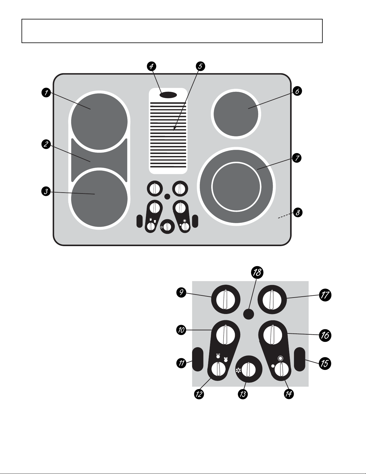
Cooktop Features
Throughout this manual, features and appearance may vary from the customer’s model.
OFF
HI
O
L
1
9
2
8
3
7
4
6
5
ON
OFF
HI
O
L
1
9
2
8
3
7
4
6
5
HOT HOT
OFF
B
E
R
G
I
D
Feature Index (Features and appearance may vary)
1 Left Rear Surface Unit
2 Bridge Surface Unit
3 Left Front Surf ace Unit
4 V ent Grille
5 V ent Filter
6 Right Rear Surface Unit
7 Dual Surface Unit
8 Model and Serial Number Label
on the right side of the vent chamber)
9 Left Rear Surface Unit Control
10 Left Front/Bridge Surface Unit Control
11 Left Side HOT Surface Indicator Lights
surface unit)
12 Bridge Select
13 V ent F an Speed Control
14 Coil Size Select
15 Right Side HOT Surface Indicator Lights
surface unit)
16 Dual Surface Unit Control
17 Right Rear Surface Unit Control
18 Surface Unit ON Indicator Light
(below the vent grille)
(under the cooktop,
(one for each
(one for each
OFF
HI
O
L
1
9
2
8
3
7
4
6
5
OFF
HI
O
L
1
9
2
8
3
7
4
6
5
HI
M
E
D
C
E
O
Z
I
I
L
S
LO
GEA00181
OFF
HI
LO
1
2
3
4
LO
1
2
3
4
HOT HOT
B
R
G
I
D
OFF
E
9
8
7
6
5
ON
HI
9
8
7
6
5
OFF
OFF
HI
LO
1
2
3
4
LO
1
2
3
4
5
OFF
9
8
7
6
HI
9
8
7
6
5
HI
M
ED
C
E
O
Z
I
I
L
LO
S
GEA00182
– 2 –
Page 5
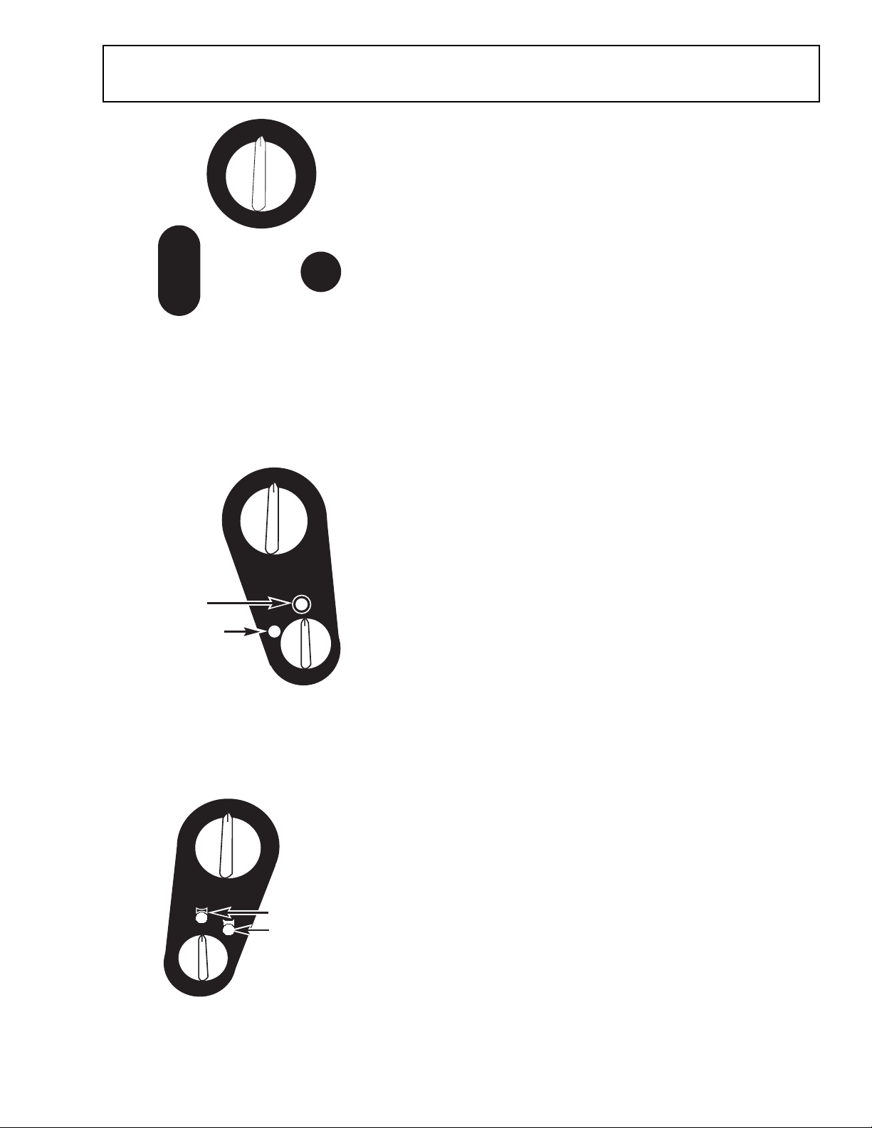
Cooktop Controls
OFF
HI
9
8
7
6
5
ON
HOT
LO
1
2
3
4
Be sure you turn the control knob to
OFF when you finish cooking.
GEA00183
OFF
HI
9
8
7
6
5
Large 9"
LO
1
2
3
4
surface unit
setting
Small 6"
surface unit
setting
C
E
O
Z
I
I
L
S
Radiant Surface Units
The control for the radiant surface unit can be set anywhere between LO and HI for an unlimited number of
heat settings. With the infinite switch, the coil cycles on
and off to maintain the selected control setting.
The surface unit’s ON indicator light will glow when any
surface unit is on.
Note: The surface unit’s ON indicator light ma y glow
between the surface control settings of LO and OFF, but
there is no power to the surface units.
The HOT surface indicator lights will glow when any
radiant element is turned on, and will remain on until the
surface is cooled to approximately 150°F.
Dual Surface Unit
To use the large (9-in.) surface unit, turn the COIL SIZE
knob clockwise to the 12 o’clock position. Push the
control knob in and turn it to the desired setting. The unit
will heat the entire area inside the larger circle.
To use the small (6-in.) surface unit, turn the COIL SIZE
knob counterclockwise to the 10 o’clock position. Push
the control knob in and turn it to the desired setting. The
unit will only heat the area inside the smaller circle.
GEA00184
OFF
LO
1
2
3
B
R
I
HI
9
8
4
E
G
D
7
6
5
Front Burner
only
Front
Burner and
Bridge
GEA00185
Bridge Surface Unit
Make sure the pan rests flat on the glass cooktop.
When the burner select knob points to the 12 o’clock
position, the control knob controls the left front surface
unit only.
When the burner select knob points to the 1 o’clock
position, the control knob controls both the left front
surface unit and the bridge area. Choose pans that
match the circle/bridge area as closely as possible.
The customer can create an oblong heated area by
using the left rear unit in addition to the front unit bridge
combination.
– 3 –
Page 6
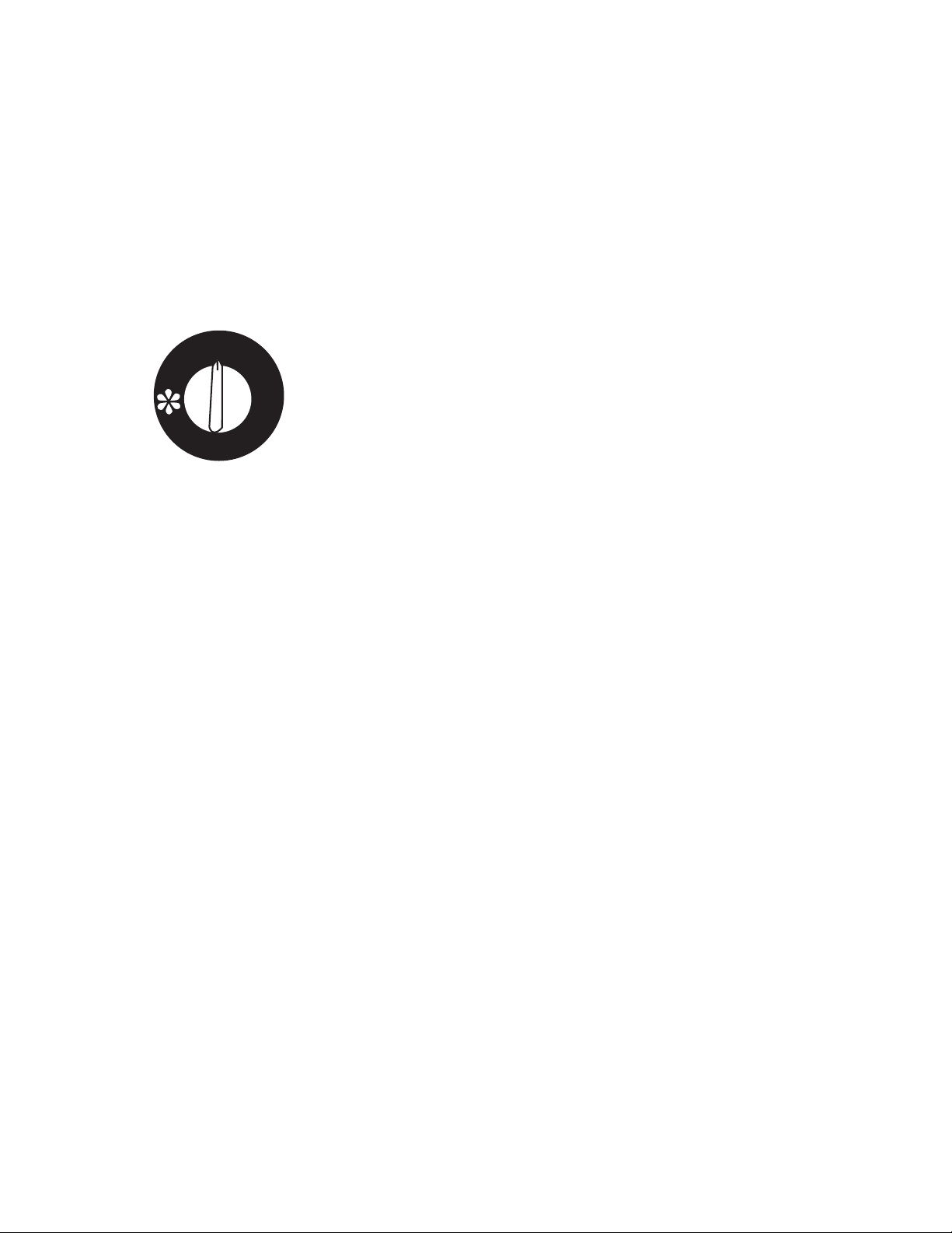
Temperature Limiter
Every radiant surface unit has a temperature limiter. The
temperature limiter protects the glass cooktop from
getting too hot.
The temperature limiter may cycle the units off for a time
if:
• The cooktop is on while cooking.
• The pan boils dry.
• The pan bottom is not flat.
• The pan is off center.
• There is no pan on the unit.
OFF
HI
MED
LO
GEA00186
How to Operate the Vent System
To operate the downdraft vent system, turn the vent fan
speed control knob to HI, MED, or LO, as needed.
– 4 –
Page 7
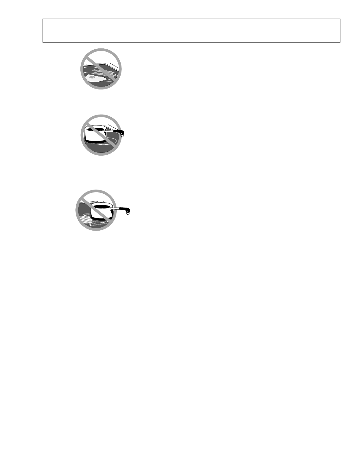
Care and Cleaning
SURFACE
COOKING
Never cook directly on the glass.
Always use cookware.
OFF CENTER
Always place the pan in the center of
the surface unit you are cooking on.
DRAGGING
Do not slide cookware across the
cooktop because it can scratch the
glass. The glass is scratch resistant,
not scratch proof.
GEA00227
Radiant Surface Units
The radiant cooktop features heating units beneath a
smooth glass surface.
Do not store heavy items above the cooktop. If they drop
onto the cooktop, they can cause damage.
Do not use the surface as a cutting board.
A slight odor is normal when a new cooktop is used for
the first time. The odor is caused by the heating of new
parts and insulating materials, and will disappear in a
short time.
On models with a white glass cooktop, it is normal for
the surface to appear discolored when it is hot. This is
temporary and will disappear as the glass cools.
The surface unit will cycle on and off to maintain the
selected control setting.
It is safe to place hot cookware from the oven or surface
on the glass surface when the surface is cool.
Water stains (mineral deposits) are removable using the
cleaning cream or full-strength white vinegar.
Window cleaner may leave an iridescent film on the
cooktop. The cleaning cream will remove this discoloration.
Daily Cleaning
WARNING: Be sure electrical power is off and all sur-
faces are cool before cleaning any part of the cooktop.
Use only a recommended cleaning cream, such as the
Cerama Brite brand or the Cooktop Cleaning Cream
brand, on the glass cooktop.
To maintain and protect the surface of the glass cooktop,
follow these steps:
• Before using the cooktop for the first time, clean it
with cleaning cream. This helps protect the top and
makes cleanup easier.
• Clean the surface with cleaning cream after each
use.
• Rub a few drops (less is better) of the cleaning
cream onto soiled areas using a damp paper towel.
Buff with a dry paper towel until all soil and cream
are removed.
– 5 –
Page 8
Using a razor scraper will not
damage the surface if the 45 angle
is maintained.
GEA00192
Note: On models with a white glass cooktop, any g rease
spatter or greasy residue from a dish towel will burn on
the cooktop when the surface units are heated, leaving a
brown stain. This can be removed with the cooktop
cleaning cream and the razor scraper. To avoid this
brown discoloration, remove any spatter with paper
towels and cooktop cleaning cream before heating any
surface unit.
Heavy, Burned-On Soil
1. Allow the cooktop to cool.
2. Apply a few drops (less is better) of cleaning cream
to the cool, soiled area. Spread the cream across the
entire soiled area.
3. Hold scraper at a 45° angle against the glass ceramic surface. This 45° angle makes the scraping
easier.
Caution: Be sure to use a new sharp razor scraper. Do
not use a dull or nicked blade.
4. Scrape soil with the enclosed razor scraper. Keep a
small amount of cream on the soil as you scrape.
Heavily soiled areas may require repeated applications of cream. It will be necessary to press down on
the razor scraper while scraping the soiled area with
cooktop cream.
5. If any soil remains, repeat the steps listed above.
To order more cream and/or scrapers for cleaning the
glass cooktop, please call our toll-free number:
National Parts Center.............................. 800-626-2002
Cleaner ....................................................... #WX10X300
Scraper.......................................................#WX5X1614
Cream Scraper Kit................................... #WB64X5027
Special Care for Sugary Spills
Caution: Be sure to use a new sharp razor scraper. Do
not use a dull or nicked blade.
Sugary spills (such as jellies, fudge, candy syrups) or
melted plastics can cause pitting of the surface of your
cooktop unless the spill is removed while still hot. This
pitting damage is not covered by the warranty. Special
care should be taken when removing these hot substances.
1. Turn off all surface units affected by the spill. Remove hot pans.
2. Wearing an oven mitt, hold the razor scraper at a 45°
angle to the cooktop. Scrape the hot spill to a cool
area outside the surface unit.
3. With the spill in a cool area, use a dry paper towel to
remove any excess. Any remaining spillage should
– 6 –
Page 9
be left until the surface of the cooktop has cooled.
Do not continue to use the soiled surface unit until all
of the spillage has been removed. Follow the steps
under Heavy, Burned-On Soil to continue the
cleaning process.
Caution: If pots with a thin overlay of aluminum, copper,
or enamel are allowed to boil dry, the overlay may bond
with the glass cooktop and leave a b lac k discolor ation.
This should be removed immediately before heating
again or the discoloration may be permanent.
Vent Filter
Vent
Chamber
GEA00190
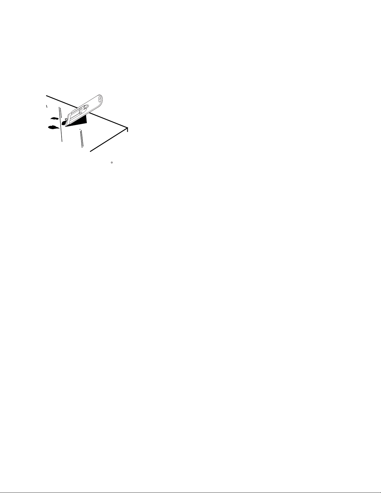
Remove and replace the filter diagonally through the
vent opening.
When replacing the filter, make
sure it rests, at an angle, on the
supports in the vent opening.
Latch it in place.
Vent System
WARNING: Before cleaning the vent grille, be sure the
exhaust blower is turned off.
To clean the vent grille,
remove it from the cooktop by
lifting it up and off. Wipe the vent grill with a damp cloth.
If necessary , the vent grille can be washed in the sink.
Use dishwashing liquid for cleaning. Do not use abrasive
cleaners, they will damage the vent grille’s finish.
Do not clean the vent grille in the dishwasher.
To clean the vent chamber,
use hot, soapy water. Do
not use abrasive cleaners, they will damage the vent
chamber’s finish.
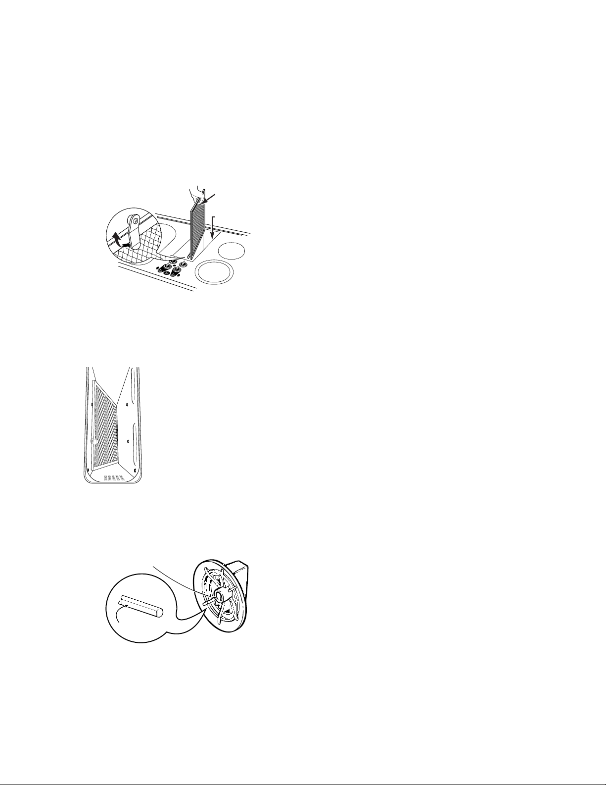
Vent Filter
Caution: Do not operate the vent without the filter in
place.
The filter is held in place with a metal latch. Move the
latch up in either direction and lift the filter diagonally up
and out of the vent opening.
GEA00189
Molded flat area
Flat
GEA00191
Clean the filter by swishing it in hot, soapy water. Rinse
well and dry thoroughly.
To order filters, please call our toll-free number :
National Parts Center..............................800-626-2002
Filter ...................................................... # WB02X10651
Control Knobs
The control knobs may be removed for easier cleaning.
Before removing the knobs for cleaning, be sure they are
in the OFF position. When replacing the knobs, check
the OFF position to insure proper placement.
Wash knobs in soap and water, but do not soak them.
Avoid getting water into the knob stem holes.
The knob stem is flat on one side (see illustration).
Check the inside of the knob and find the molded flat
area.
Replace the knob by fitting the molded flat area inside
the knob onto the flat area of the stem.
– 7 –
Page 10
Installation Requirements
Before you begin, read these instructions
completely and carefully.
Note: Save these instructions for local inspector’s
use.
• Observe all governing codes and ordinances.
• Installation of this unit requires 2 people. Do not
attempt to install without assistance.
• This appliance must be properly grounded.
Tools and Materials You Will Need:
•Saw
• Flat blade screwdriver
• Electrician’s pliers
• Duct tape
• Measuring tape or scale
• Carpenter’s square
• Wrench or socket set
• Drill and drill bit
• Sheet metal screws
• Junction box*
• 1/2 in. flexible conduit*
• Electrical cable per local code*
• Wire nuts*
• Duct work
*Note: Electrical installation kit JXCK89 may be
ordered separately and includes all the parts
necessary to connect the cooktop to typical roughin wiring.
Electrical Requirements
WARNING: F or personal saf ety, remove house fuse
or circuit breaker before beginning installation.
This appliance must be supplied with the proper
voltage and frequency, as listed in these Installation Requirements, and connected to an individual, properly grounded branch circuit, protected
by a 40-amp circuit breaker or time-dela y fuse.
All wire connections must be made in accordance
with local codes and properly insulated. Check
with your local utility for governing electrical codes
and ordinances. In the absence of local electrical
codes, the National Electrical Code, ANSI/NFPA
No. 70–Latest Edition, governing electric range
installations, must be follo wed.
A copy of the National Electrical Code can be
obtained by writing to:
National Fire Protection Association
Batterymarch Park
Quincy, MA 02260
Effective January 1, 1996, the National Electrical
Code requires that new, but not existing, construction utilizes a four-conductor connection to an
electric range. When installing an electric range in
new construction, follow the instructions in New
Construction and Four-Conductor Branch
Circuit Connection.
You must use a three-wire, single-phase AC
208Y/120-Volt or 240/120-Volt, 60-Hertz electrical
system with separate ground. If you connect to
aluminum wiring, properly installed connectors
approved for use with aluminum wiring must be
used.
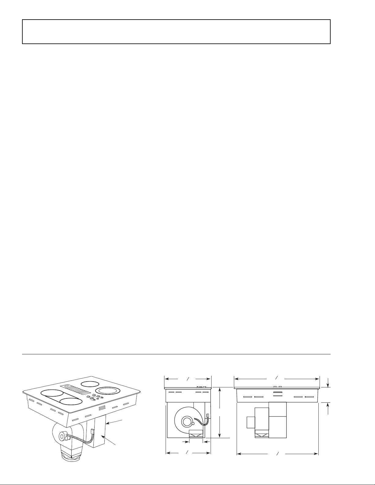
30" Cooktop (Dimensions for reference only)
Nomenclature
(on other side)
Mini-manual
located behind
cover
– 8 –
7
21 "
1
20 "
Unit must be vented to the outside!
8
19"
6"
Dia.
2
29 "
28 "
7
8
6"
7
8
GEA00193
Page 11
Sufficient air is needed for proper combustion and exhausting of gases through the flue (chimney)
of fuel-burning equipment to prevent back drafting. Follow the heating equipment manufacturer’s
guidelines and safety standards such as those published by the National Fire Protection Association (NFPA), the American Society for Heating, Refrigeration and Air Conditioning Engineers
(ASHRAE), and the local code authorities.
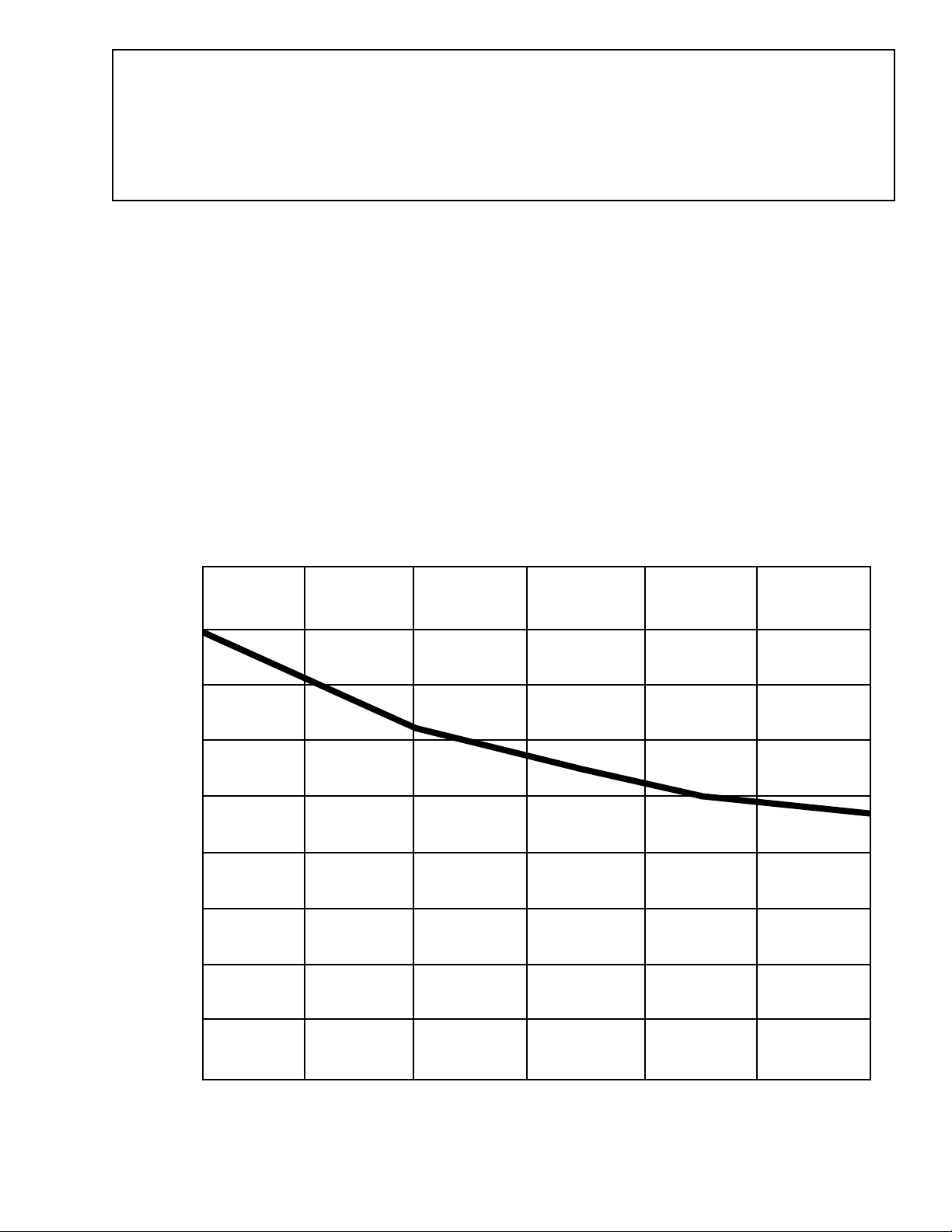
Note: The exhaust blower output is approximately 400 CFM (cubic feet per minute) without ductwork.
Each installation is different and ductwork affects blower output accordingly. Actual blower exhaust CFM
can be approximated using the graph below.
Step 1: Calculate the “equivalent duct length” using Table 1 on page 13 of these instructions for
your installation.
Step 2: Find the approximate intersection point of the blower exhaust perfor mance curve with the
equivalent duct length to estimate the actual maximum blower output for your installation.
Examples: 50 equivalent ft of ductwork have approximately 320 CFM. 100 equivalent ft of ductwork
have approximately 265 CFM.
450
400
350
300
250
200
Air Flow (CFM)
150
100
JP989 Downdraft Cooktop Exhaust Blower CFM
50
0
0 25 50 75 100 125 150
6-in. Diameter Equivalent Duct Length
6 in. Diameter Equivalent Duct Length
– 9 –
GEA00303
Page 12
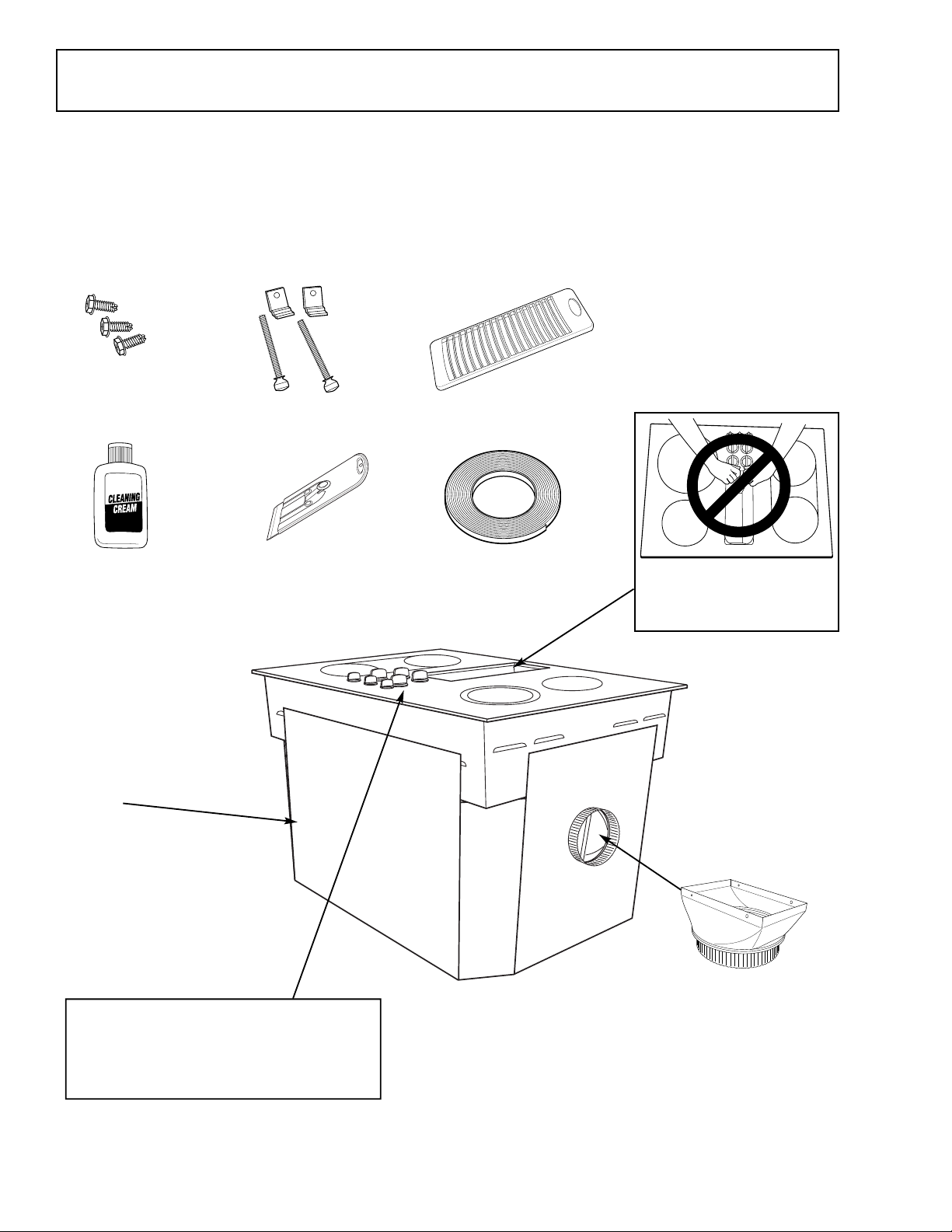
Unpacking Cooktop
Parts Included:
• (2) Hold-down retainers and screws
• Blower discharge duct transition to 6-in. round
pipe
• (3) Sheet metal screws
• Foam gasket tape (9-ft. roll)
• Vent grille
• Cleaning cream
• Cleaning Scraper
Sheet Metal
Screws
Cleaning Cream
Note: Leave the
cooktop resting
on the cardboard
sleeve until ready
to install in the
cabinet.
Hold-down Retainers
and Screws
Cleaning Scraper
Vent Grille
Foam Gasket Tape
CAUTION:
DO NOT LIFT FROM
VENT OPENING
CAUTION: GLASS IS FRAGILE
DO NOT BUMP EDGE OF GLASS
DURING INSTALLATION
– 10 –
Blower Discharge
Transition Duct
(Packed in Cardboard
Sleeve)
GEA00304
Page 13

Cabinet Preparation
5
3
4
"
Approx.
5
3
4
" Approx.
for European
cabinets
GEA00196
Step 1 – Preparing for Installation
Positioning the cooktop
The cooktop is designed to look best when cen-
tered in a cabinet its same width.
The exhaust vent beneath the cooktop must be
located between wall studs or floor joists so that
ductwork may be installed properly.
At least 6 in. must be allowed between side edges
of cooktop and adjacent walls.
1/2" Flat area
30"
15"
1
1
2"
for support
6 " Min. to
side wall
Step 2 – Preparing the Base Cabinet
This cooktop is designed to fit easily into a variety
of cabinets. However, some cabinets may require
modifications.
Preparing a cabinet that is against a wall
In some cabinets, the sides may need to be
scooped or cut down 5-3/4 in. as shown, and the
corner braces need to be removed in order to
accommodate the unit.
In 75-cm and 90-cm frameless European cabinets, the back panel may need to be cut down
5-3/4 in. to accommodate the unit.
Preparing a peninsula- or island-type cabinet
In a peninsula- or island-type cabinet, the sides
may need to be scooped or cut down, and the
corner braces need to be removed in order to
accommodate the unit.
GEA00195
Avoid placing cabinets above the cooktop unit, if
possible, in order to reduce the hazards caused by
reaching over heated surface units. If cabinets are
placed over the cooktop, the risks can be reduced
by installing a range hood that projects horizontally a minimum of 5 in. beyond the bottom of the
cabinets.
If cabinetry is used above cooktop, allow a minimum 30-in. clearance between the cooking surface and the bottom of any unprotected cabinet.
If clearance between cooktop and cabinetry is less
than 30-in., cabinet bottom must be protected with
flame-retardant millboard at least 1/4-in. thick,
covered with 28-gauge sheet steel or 0.020-in.
thick copper. Clearance between cooktop and
protected cabinetry must never be less than 24 in.
Exception: Installation of a listed microwave oven
or cooking appliance over the cooktop shall conform to the installation instructions packed with
that appliance.
A 15-in. minimum must be kept from the side edge
of cooktop to the bottom of any cabinet not directly
above cooktop. If clearance is less than 15 in.,
adjacent cabinets should be at least 6 in. from
side edges of cooktop.
– 11 –
Step 3 – Rough Preparation of Junction Bo x
WARNING: For personal safety, remove house
fuse or open circuit breaker before preparing
junction box.
Install an approved junction box within shaded
area shown in diagram. Junction box must be at
least 10-1/2 in. below the top of the cabinet.
Run conductors from residence wiring to junction
box according to local electrical codes.
C
L
9"
4"
16 "
20"
10
1
2
"
GEA00197
Page 14

Step 4 – Preparing the Countertop
Step 5A – Blower to Ductwork Alignment
Clearance between inside front of cabinet and rear
of countertop cutout must be 20-5/8 in. in order to
accommodate cooktop depth.
5
20
8"
3
8" Min.
2
GEA00198
A 1/2-in.-wide flat area is required around the
edge of the opening to support the unit. The
cooktop unit must be level and sit squarely into the
countertop opening.
Carefully cut countertop opening according to the
dimensions shown in the illustration. Be sure the
opening is cut squarely, with sides parallel to each
other and rear exactly perpendicular to sides.
5
20
8
"
In general, the use of flexible ducting is discouraged because it can cause severely restricted
airflow. However, if the blo wer outlet and the floor
or wall duct location do not align well, then flexible
metal ducting can be used to adapt to an offset.
Good alignment without use of flexible ducting is
best.
Note: Do not exceed the maximum recommended
offset of 6 in.
• Do not allow the flexible ducting to kink or
collapse.
• Do stretch the flexible ducting as much as
possible to eliminate as much of the corrugation
as possible.
6" Max.
Centerline
to Centerline
Offset
25"
2
3
8
" Min.
28
7
8
"
GEA00199
Step 5 – Preparing for Ductwork
Note: Ductwork must be vented to outside. Do
not vent into a wall, ceiling, crawl space, attic, or
other concealed space.
• When cutting or drilling into wall or ceiling, do
not damage electrical wiring or other hidden
utilities.
Cut hole in cabinet wall or floor as appropriate for
your installation. Make sure exhaust duct is located between wall studs or floor joists.
1
9
8
"
3
4
"
8
1
8
"
10
6
Bottom Venting
Back Venting
(Requires Kit JXRW89)
Step 5B – Determine Flexible Ducting’s
Equivalent Length
1. Measure the actual amount of offset (maximum of 6 in. is recommended). The effect
upon airflow is dependent upon the amount of
offset.
2. Calculate the equivalent ducting allowances
using:
(___ in. offset) x (5 ft. per inch)
= ___ ft. equivalent length
3. Enter the calculated value into Table 1 of
1
8
"
Ductwork Calculations.
4. Ensure that the total equivalent length of
ducting does not exceed the maximum recommendation of 100 ft.
GEA00305
Rear Wall Venting
Downward Venting
GEA00201
– 12 –
Page 15

Ductwork Calculations
Equivalent Number Equivalent
Duct Pieces Length* x Used = Length
6" round
to 3
1
4
" x 10 "
transition
90 elbow 20 ft. x ( ) = ft.
3
1
4
" x 10"
to 6"round
transition 5 ft. x ( ) = ft.
3
1
4
" x 10"
to 6"round
transition
90 elbow 12 ft. x ( )= ft.
6"round
wall cap
with damper 21 ft. x ( ) = ft.
3
1
4
" x 10"
wall cap
with damper 27 ft. x ( ) = ft.
6"round
roof cap 20 ft. x ( ) = ft.
6"round
roof vent 24 ft x ( ) = ft.
Subtotal Column 2 = ft.
Subtotal Column 1 =
Should not exceed 100 feet.
ft.
TOTAL DUCTWORK =
ft.
GEA00203
TABLE 1
Calculate Total Equivalent Ductwork Length
Duct Pieces Length*x Used = Length
6" round
straight 1 ft. x ( )= ft.
1
3
4
" x 10"
straight 1 ft. x ( ) = ft.
6", 90
elbow 15 ft. x ( ) = ft.
6", 45
elbow 9 ft. x ( )= ft.
Flexible
Metal Offset See Calculations
Adapter in Steps 5A and 5B ft.
Equivalent Number Equivalent
1
3
4
" x 10"
90 elbow 16 ft. x ( ) = ft.
1
3
4
"x 10"
45 elbow 5 ft. x ( )= ft.
1
3
4
" x 10"
90 flat elbow 18 ft. x ( )= ft.
6" round
1
to 3
4
"x 10"
transition 7 ft. x ( ) = ft.
*
Equivalent lengths of duct pieces are based on actual tests
and reflect requirements for good venting performance with
any downdraft cooktop.
†
Measure and list feet of straight duct used. Count and list
the quantity of all other duct pieces for the “Number Used”
of each type.
Note: For maximum efficiency, use the shortest
and straightest duct run possible, with as few
fittings as possible.
the duct run should not exceed 100 ft equivalent
length.
Subtotal Column 1 = ft.
For satisfactory performance,
GEA00202
Note: Do not use flexible plastic ducting.
If flexible metallic ducting is used, all the equiva-
lent feet values in the table should be doubled.
The flexible metallic duct should be straight,
smooth, and extended as much as possible.
Vent installation should not exceed the equivalent
ductwork length of 100 ft.
Blower is rated at 400 CFM at 0.1 inch of water
back pressure.
Venting performance is improved by using larger
diameter duct.
– 13 –
Page 16

Ductwork Installation
Step 6 – Installing the Ductwork
Note: Local building code must be followed in
specifying approved type and schedule of all duct
used.
Use galvanized or aluminum duct in 6-in. round or
3-1/4-in. x 10-in. size, or a combination of both.
PVC duct should be used if installing under a
poured concrete slab.
Always use an appropriate roof or wall cap with a
damper. Laundry-type wall caps should never be
used.
Thru Cabinet Toe Space Between Floor Joist
Downward Venting
GEA00204
Install ductwork, making male-female connections
in the direction of airflow as shown. Secure all
joints with sheet metal screws and duct tape to
assure an airtight seal.
for rear wall and retrofit installations.
A 5-in. round duct may be used on short duct runs
of 3 ft or less, such as direct to outside wall venting.
Inside Wall to Roof Direct to Outside
Rear Wall Venting
GEA00206
To convert blower exhaust direction, remove
7/16-in. nuts (behind the filter) that hold blower
and wire finger guard. Remove blower and install
Special Offset Adapter Kit JXRW89 with sheet
metal screws.
Duct Tape Over Seam
and Screw
Air Flow
Screw
GEA00205
Use the shortest and straightest duct run possible.
For satisfactory performance, the duct run should
not exceed the equivalent ductwork length of 100
ft. Use Table 1 to calculate the total equivalent
length of the ductwork.
Optional Installation: Rear Wall Venting
Rear wall venting requires a special offset duct
adapter (JXRW89) that is not included with your
cooktop. This adapter has a 5-in. diameter outlet
4 Nuts
Behind Filter
(7/16"socket
required)
GEA00306
Rotate blower and reinstall to vent chamber, as
shown above. Retighten nuts, but do not overtighten.
– 14 –
Page 17

Step 7 – Installing the Foam Gasket
GEA00310
Underside of Glass
1
8
"max. to
Glass Edge
Foam Gasket
Tape
Do not tape
over four
metal
brackets
Caution: Do not install the cooktop into the
countertop without installing the foam gasket, as
shown below. The foam gasket protects the bottom edge of the glass from the countertop and
seals the cooktop to protect it from spills.
Foam Gasket Installation Notes:
• The foam gasket tape should be installed
within 1/8 in. of the edge of the glass. Do not
stretch or twist the foam gasket tape.
• Use care not to stretch the foam gasket tape
while it is installed or it will not stay in place.
Start with the cooktop on the cardboard base with
all four sides easily accessible.
GEA00307
Locate the foam gasket tape included with
the cooktop.
• Do not place foam gasket tape over the four
metal mounting brackets.
• Butt the foam gasket tape ends together at each
corner without overlapping.
• Trim the foam gasket tape to length without
stretching.
• Mitre cut outside corners of foam gasket tape
slightly if necessary for appearance.
• Do not scratch the glass while cutting the foam
gasket tape.
GEA00308
Peel off the white backing to install the foam
gasket tape on the bottom side of the cooktop
glass, as shown below.
GEA00309
– 15 –
Page 18

Cooktop Installation
Step 8 – Installing the Cooktop
Place the vent grille in position on the glass top
vent opening. Remove the tape holding the cardboard base to the bottom of your cooktop.
CAUTION:
DO NOT LIFT
FROM VENT
OPENING
Step 9 – Checking for Flatness
Inspect the cooktop glass for rocking or uneven
gap on all four sides at the countertop surface. Do
not attempt to force the glass to meet the
countertop.
Check for
uneven gaps
Note: If the cooktop edge is perfectly flat with the
countertop surface, skip to Step 10.
If there is rocking or an uneven gap, use a 1/4-in.
nut driver to loosen the 18 sheet metal screws on
the bottom panels of the cooktop while it is still in
the countertop.
GEA00209
GEA00311
Caution: Do not use the glass top vent opening to
lift or move the cooktop into position.
Using two people, lift the cooktop by the glass side
edges as shown. Remove the cardboard base.
GEA00208
Lower the cooktop into the countertop opening,
guiding it into position until the glass is approximately 1/2-in. above the countertop surface.
Carefully remove your fingers one corner at a time
to lower the cooktop into position.
Note: Do not use Silicone RTV or caulk to bond
cooktop glass to countertop.
Loosen
screws
1-2 turns
Loosen
screws
1-2 turns
GEA00210
Loosen each bottom panel screw 1 or 2 turns.
After all 18 screws are loosened, recheck the
cooktop for flatness with the countertop surface.
Gently bump your hand along the outside edge of
the cooktop if needed to help the edge settle
evenly onto the countertop surface.
Retighten all 18 sheet metal screws.
Grounding Specifications:
Ground Path Resistance: 0.10 Ohm Max.
Insulation Resistance: 250K Ohm Min.
– 16 –
Page 19

Step 10 – Installing the Hold-Down
Screws
Screw
(on other side)
GEA00212
Retainers
Step 11 – Attaching the Blower T ransition
Duct
Note: Check for glass flatness discussed in Step 9
before installing hold-down retainers.
Countertop
Thumb screw
Use slot position
appropriate for
countertop thickness
Hold-down retainer
GEA00211
Hold down
retainer
GEA00312
Secure cooktop to the counter using the side
retainers and thumb screws shipped with the unit
(one on each side).
Use the blower transition duct that is packed with
your cooktop for all downward duct installations to
connect to 6-in. round standard ductwork.
Note: Use Rear Wall Adapter Kit JXRW89 for duct
installations through the rear cabinet wall and
retrofits of older 5-in. duct size cooktops.
Remove the cardboard packing in the blower
outlet.
Install the transition duct to the blower outlet with
the 3 sheet metal screws that are provided.
Step 12 – Connecting the Ductwork
Connect the ductwork prepared in Steps 5 and 6
to the blower transition duct.
– 17 –
Page 20

Electrical Installation
Step 13 – Before Making Electrical
Connections
Note to Electrician: The power leads supplied
with this appliance are U.L. recognized for connection to large-gauge household wiring.
The insulation of these leads is rated at temperatures much higher than the temperature rating of
household wiring. The current-carrying capacity of
a conductor is governed by the wire gauge and
the temperature rating of the insulation around the
wire.
Aluminum Wiring
WARNING: Improper connection of aluminum
house wiring to the copper leads can result in
serious problems.
Attach copper wires to aluminum wiring using
special connectors designed and U.L. listed for
joining copper to aluminum. Follow the connector
manufacturer’s recommended procedure closely.
Service Loop
Leave a loop in the wires to the cooktop so the
cooktop can be lifted 12 in. without having to
disconnect the wiring.
Electrical Requirements*
Model # Voltage Frequency kW
JP989 120/240 V 60 Hz 8.8 kW
120/208 V 60 Hz 6.7 kW
*For reference only. Verify with product rating plate.
Step 14 – Install 1/2-in. Flexible Conduit
With Supplied Clamp
Note: A clamp has
been included with the
cooktop for installing
the 1/2-in. flexible
conduit.
Remove the screws
holding the wire
compartment cover
and remove the cover.
Alternate
External
Ground
Screw
Clamp
Stop Tab
Clamping
Screw
Clamping Tab
Feed the power supply
leads through the
conduit; be sure to
leave enough length
to properly connect
these leads to the
cooktop power leads.
Thread the leads
through an anti-short
bushing and firmly seat
the anti-short bushing
in the end of the
conduit.
Feed the leads through
the hole in the wire
compartment.
Lay the conduit against
the side of the wire
compartment.
Place the clamp over
the conduit. Make sure
the bushing is fully
seated against the
stop tab in the clamp.
Tighten the clamping
screw until the
clamping tab is fully
seated against the
wire compartment.
When complete,
reinstall the wire compartment cover.
Power Supply
Leads
Bushing (Fully Seated)
Clamp
Stop Tab
Clamping
Tab
Clamping
Screw
Clamping
Tab
Anti-Short
Bushing
Conduit
GEA00214
GEA00215
GEA00216
GEA00217
Remove the clamping screw
and the clamp.
GEA00213
– 18 –
Page 21

Step 15 – Making Electrical Connections
3-Conductor Branch Circuit
Branch Circuit
Power
Supply
Leads
Cooktop
Power
Leads
Red Red Red
White or
Gray
White or
Gray White
Black Black Black
Green
NEUTRAL
120V AC
120V AC
GEA00218
Effective January 1, 1996, the National Electrical
Code requires that new, but not existing, construction utilizes a four-conductor connection to an
electric range. When installing an electric range in
new construction, follow the instructions in New
Construction and Four-Conductor Branch
Circuit Connection.
You must use a three-wire, single-phase AC 208Y/
120-Volt or 240/120-Volt, 60-Hertz electrical
system with separate ground. If you connect to
aluminum wiring, properly installed connectors
approved for use with aluminum wiring must be
used.
New Construction and Four-Conductor Branch
Circuit Connection
• When installing in new construction, or
• When installing in a mobile home, or
• When local codes do not permit grounding
through neutral:
Three-Conductor Branch Circuit Connection
• When installing in existing construction built prior
to January 1, 1996 and if permitted by local codes:
3-Conductor Branch Circuit
When connecting the cooktop to a 3-conductor
circuit, connect the red leads of the cooktop and
the power supply to the branch circuit’s red lead;
connect the black leads to each other. Connect the
green and white leads of the cooktop to the power
supply and branch circuit neutral leads, which are
white or gray.
4-Conductor Branch Circuit
When connecting the cooktop to a 4-conductor
circuit, connect the red leads of the cooktop and
the power supply to the branch circuit’s red lead;
connect the black leads to each other. Separate
the green and white leads of the cooktop. Connect
the cooktop’s white lead to the power supply and
branch circuit neutral leads, which are white or
gray. Ground the unit by connecting the green
conductor of the cooktop to the bare or green
leads of the power supply and branch circuit
(ground leads).
4-Conductor Branch Circuit
120V AC
120V AC
NEUTRAL
Branch Circuit Power
Red Red Red
White or
Gray
Black Black Black
Supply
Leads
White or
Gray White
Cooktop
Power
Leads
Bare or
GND
Green
Bare or
Green Green
GEA00219
– 19 –
Page 22

Removal and Replacement
Control Assembly Servicing:
Infinite Switches, Coil Select Switches,
Blower Switch, and ON Lamp Servicing
Caution: This cooktop has instant-on HOT surface
indicator lights. Wiring reversals can cause a direct
electrical short after all 4 surface units heat up and
close all 4 limiter switches. Check the wire termina-
tions for proper polarity of all L1 and L2 wires, H1 and
H2 wires, and heater HOT light terminals #2 and #4.
Note: Control assembly can be removed from the
cooktop without removing the cooktop from the
countertop.
1. Remove all 7 knobs from the cooktop.
Note: Remove any knob clips that remain on the control
shafts and reinsert clips inside knob stems.
2. Remove 4 screws and the wiring access cover
located below the controls. Disconnect the white 5pin blower connector inside.
3. Remove 3 screws that hold the component plate to
the cooktop. The screws are above the wiring with 2
toward the front and 1 toward the rear.
A
Screws
Screw
(on other side)
GEA00232
Caution: Save and replace with the exact screws to
prevent glass breakage (#8-18 x 1/4-in.).
4. Unplug the 2 red and 2 white connector housings.
5. Lower the control assembly and rotate the front side
down to remove.
Blower Assembly Replacement (WB26X10072)
Note: Blower assembly can be removed from the cook-
top without removing the cooktop from the countertop.
• The blower is a three-speed tapped winding design
with a permanent run/start capacitor.
1. Remove the access wiring cover located below the
controls (4 screws, see figure).
2. Unplug the blower connector and remove the wires
from the access cover.
3. Disconnect the transition duct from the blower
assembly.
4. Remove the intake grille and filter.
5. Support the blower assembly and remove the
7/16-in. nuts (A) inside the intake plenum.
GEA00300
Parts available: Complete bl o w er assembly with capacitor or replacement capacitor WB27X10363.
– 20 –
Page 23

GEA00319
Terminals
GEA00320
Terminals
Terminals
Capacitor Replacement (WB27X10363)
WARNING: Disconnect the electrical power supply
before servicing the capacitor. The capacitor is capable
of storing voltage that could be lethal. Do not touch the
bare connector terminals.
1. Remove the guard surrounding the capacitor shell.
Some models have a flat plastic spacer between the
capacitor shell and the motor. Retain the guard and
the spacer for reassembly.
2. Firmly push upward on the capacitor shell to remove
the capacitor from motor bracket cap.
WARNING: Make sure the stored electrical charge has
been dissipated by placing a 100-ohm, 2-watt resistor
across the terminals, or by placing a screwdriver blade
between the terminals and grounding the screwdriver to
the cooktop for several seconds.
3. Carefully discharge both capacitor wire harness
terminals as described above.
Note: Record wire harness connections.
4. Disconnect terminals using needle nose pliers and
reconnect in same orientation on new capacitor.
5. Firmly snap new capacitor shell casing into motor
bracket cap.
6. Replace plastic spacer (if so equipped) and guard
around capacitor.
GEA00321
HOT Light Replacement
AA
Note: HOT lights can be removed from the cooktop
without removing the cooktop from the countertop.
CC
BB
• The HOT lights and the surface heater ON light are
120-V lights with dual bulbs (WB25K10003).
• It is recommended to remove the blower if ser vicing
the left side HOT lights.
1. Remove the large bottom cover under the HOT
GEA00236
lights.
2. Remove 2 screws (A) and the HOT light bracket.
Caution: Save and replace with the exact screws to
prevent glass breakage (#8-18 x 1/4-in.).
3. Remove the wires (B) to the HOT lights.
4. Compress the HOT light wings (C) and remove
them.
– 21 –
Page 24

Countertop
Hold-down retainer
Glass Cooktop Removal from Countertop
(Required for heater replacement or broken glass
cooktop replacement.)
WARNING: To avoid injury to eyes from ceramic fiber
dust, heater assemblies should be serviced by removing
the entire cooktop from the countertop opening and
removing the glass assembly from the chassis.
Caution: Fiber ceramic material on the heating element
is very fragile–avoid contact.
• When servicing cooktop, care must be taken not to
scratch the glass.
1. Remove the wiring access cover located below the
controls (4 screws). Do not remove flex cable clamp
from wiring access cover. Disconnect the white 5-pin
blower connector inside.
2. Remove all cooktop hold-down retainers from
underneath the counter top’s edge.
3. Remove the blower (see Blower Assembly
Replacement) to reduce the weight of the cooktop
for safe removal from countertop. Do not remove
wires from access cover.
4. Protect the counter with two strips of wood or cardboard as shown.
Thumb screw
GEA00211
GEA00231
Caution: T o avoid
cooktop glass breakage,
do not lift or support the
cooktop using the
downdraft vent opening.
5. Reach up from inside the cabinet and push upward
on the burner box bottom enough to shim with
protective wood or a cardboard piece under one end.
Repeat for the other end.
Caution: Screws on the bottom of the burner box can
scratch the countertop surface. Use care to protect
countertop appearance.
6. Using the shims to get a handhold under the left and
right sides of the glass, carefully raise the cooktop
up about 7 inches, rotate slightly left or right (to best
working advantage), and set down as shown. Lift
each end slightly and adjust wood or cardboard as
shown to prevent scratching the countertop.
Note: Have an 18- to 24-in. prop rod (stiff enough to
hold 15 lbs. of compression) at hand.
– 22 –
Page 25

Side Wall
Side Wall
2 White
Spring Clip and
Coil Spring
7. Remove (12) 1/4-in. chassis screws (A) that hold the
glass and metal subplate to the cooktop box (3
screws from each side).
8. Raise the front of the glass and metal subplate
assembly slightly and use pliers to bend 2 tabs (B)
approximately 45 degrees outward.
9. Carefully raise the glass and metal subplate assembly from the cooktop box. Do not force it. Wires may
be caught on the flanges of the cooktop box.
CBAA
GEA00234
10. Insert the 2 tabs (B), on the front of the metal
subplate, into the 2 slots (C) on the top front flange
of the cooktop box.
11. Tilt the glass and metal subplate up and temporarily
install the prop rod near the center as shown.
Note: If you are replacing only 1 defectiv e heater using
Heater Replacement Method 1, skip to that section to
Prop
Rod
continue. Otherwise, go on to step 12.
12. Remove all 7 knobs from the cooktop.
Note: Remove any knob clips that remain on the control
shafts and reinsert clips inside knob stems.
Side Wall
Side Wall
Slot Opening
Slot Opening
2 White
2 White
Connectors
Connectors
Screws
Screws
GEA00233
Side Wall
Side Wall
Slot Opening
Slot Opening
2 Red
2 Red
Connectors
Connectors
GEA00301
13. Unplug the 4 connectors below the controls (2 red
and 2 white connectors).
14. Push the heater side of the connectors through the
sidewall slot openings (2 red connectors go to the
right and 2 white connectors to the left).
15. Have a 1/4-in. nut driver ready, then tilt the glass and
metal subplate assembly up to a fully vertical position and remove 2 screws from the bottom of the
center control panel plate.
Caution: Save and replace with the exact screws to
prevent glass breakage (#8-18 x 1/4-in.).
16. Retur n the glass and metal subplate back to the
tilted position supported by the prop rod, then remove the top screw from the center control panel
plate.
17. Pull the control panel plate away from the glass until
all 7 shafts pull out of the rubber grommets. Let the
control panel rest on the top of the burner box
chassis.
Note: If you are replacing a broken glass cooktop, skip
to Broken Glass Replacement section.
• If you are replacing a defective heater, skip to the
Heater Replacement Method 2 section.
– 23 –
Page 26

Heater Replacement Method 1 –
Using the prop rod.
This method has fewer steps than Method 2, but has a
higher risk of twisting and breaking the glass during
replacement of the heater. Use this method only if you
have good access to reaching around the propped
cooktop to replace the heater.
Perform Steps 1. thru 11. in the Glass Cooktop Re-
moval from Countertop section, then skip to Step 20.
in Method 2 below.
Note: To avoid glass breakage, use care not to twist or
lean on the glass cooktop while it is supported by the
prop rod.
Heater Replacement Method 2 –
Using a tabletop.
Perform Steps 1. thru 17. in the Glass Cooktop Re-
moval from Countertop section.
Metal
Tabs
HOT Light
Bracket Screws
Hairpin Cotter
Clips and Springs
Rubber Grommets
GEA00302
18. Have a clean, flat tabletop or countertop (at least
30 in. wide) available. Remove the prop rod and lift
the glass and metal subplate assembly away from
the burner box chassis.
19. Place the glass and metal subplate assembly appearance side down on the table with the 7 grommets off the front of the table. This is to prevent
glass breakage while replacing heaters.
Caution: Only about 2/3 of the glass is resting on the
table. Do not push down on the front 1/3 without supporting the front of the glass with your hand. Do not
force the glass assembly forward, as it will damage the
Left-Rear and Right-Rear infinite switch grommets.
20. Remove the heater’s hairpin cotter clips and springs
from the defective heater.
21. Remove the defective heater with wiring intact and
lay to one side.
22. Install the new heater in position. Make sure the
metal locating tabs do not go inside the metal heater
can during assembly.
23. Reinstall the springs and hairpin cotter clips.
Note: If you are replacing either the bridge heater or the
dual heater, it is easier to complete the wiring if you
temporarily remove the HOT light bracket to provide
hand access to terminals.
Caution: Save and replace with the exact screws to
prevent glass breakage (#8-18 x 1/4-in.).
24. Remove heater wires, one at a time, from the defective heater and place them on the exact terminal
positions on the new heater.
– 24 –
Page 27

Caution: The cooktop has instant-on HOT surface
indicator lights. Wiring reversals can cause a direct
electrical short after all 4 surface units heat up and
close all 4 limiter switches. Check the wire termina-
tions for proper polarity of all L1 and L2 wires, H1 and
H2 wires, and heater HOT light terminals #2 and #4.
25. Carefully shape the heater and HOT light wires to
avoid the center chassis rails, but do not allow the
wires to touch the metal heater cans.
26. Skip to Reinstalling Glass Cooktop section to
complete reassembly and installation into
countertop.
Broken Glass Replacement
Caution: Fiber ceramic material on the heating element
is very fragile–avoid contact.
• When servicing the cooktop, care must be taken not to
scratch the glass.
• The cooktop has instant-on HOT surface indicator
lights. Wiring reversals can cause a direct electrical
short after all 4 surface units heat up and close all 4
limiter switches. Check the wire terminations for proper
polarity of all L1 and L2 wires, H1 and H2 wires, and
heater HOT light terminals #2 and #4.
Shorter Tabs
Foam Tape
GEA00322
Note: The glass cooktop should be serviced by removing the entire cooktop from the countertop opening. The
glass and metal subplate are sealed together and are
replaced as an assembly.
1. Carefully open one end of the package containing
the replacement glass cooktop, then slide out the
B
glass and protective styrofoam packaging. Save a
packet of 1/4-in.-wide foam gasket tape for Step 4.
2. Place one piece of the flat syrofoam packaging on a
smooth tabletop and place the new glass subassembly face up. Check for any breakage or damage
before proceeding. Flip the glass face down onto the
styrofoam block with the control holes toward you.
Do not remove nylon filament tape from the glass
edge.
3. Using a pair of pliers, gently bend back only the
shorter tabs around each heater opening about 5
degrees to ease assembly of the heaters later.
4. Install new 1/4-in.-wide foam gasket tape
(WB25K10003) along the outer edge of the glass, on
top of the nylon filament tape.
5. Place the other piece of flat styrofoam packaging
beside the new glass subassembly as a place to put
the old glass subassembly when removed from the
cooktop chassis. This provides a side-by-side work
area to transfer heaters and HOT lights safely to the
new glass subassembly.
– 25 –
Page 28

6-in. Heater
Metal
Tabs
Dual
Heaters
Hairpin Cotter
Clips and Springs
HOT Light
Bracket Screws
Bridge
Heater
Rubber Grommets
GEA00323
Perform Steps 1. thru 17. in Glass Cooktop Removal
from Countertop section.
18. Verify that the flat styrofoam packing material from
the new glass subassembly is in place on a table or
countertop to be used as a work surface.
19. Place the broken glass and metal subplate assembly
appearance-side down on the above-mentioned
styrofoam packing surface.
20. Remove 7 rubber grommets from the broken glass.
Wet the rim of all 7 holes in the new glass by using a
drop of liquid soap on your fingertip to lubricate the
hole before reinstalling the grommets. Gently twist
(do not force) the grommet through the hole.
21. Remove the heater’s hairpin cotter clips and springs
from the 6-in. heater, the bridge heater, and the dual
heater.
22. Remove 2 special screws from each HOT light
bracket on the left and right sides.
Caution: To prevent glass breakage, save and replace
with exact screws (#8-18 x 1/4-in.).
23. Lift out the bridge heater with the wiring and HOT
lights intact and transfer to the new glass. Make
sure the metal locating tabs do not go inside the
metal heater can during assembly.
24. Lift out the 6-in. and dual heaters together with
wiring and HOT lights intact and transfer them to the
new glass assembly in a similar manner.
25. Reinstall all heater springs and cotter hairpin clips.
26. Reinstall both left and right HOT light brackets using
the special #8-18 x 1/4-in. screws.
Caution: The cooktop has instant-on HOT surface
indicator lights. Wiring reversals can cause a direct
electrical short after all 4 surface units heat up and
close all 4 limiter switches. Check the wire termina-
tions for proper polarity of all L1 and L2 wires, H1 and
H2 wires, and heater HOT light terminals #2 and #4 if
any wires were removed.
27. Carefully shape the heater and HOT light wires to
avoid the center chassis rails, but do not allow the
wires to touch the metal heater cans.
Proceed to Reinstalling Glass Cooktop section to
complete reassembly and installation into countertop.
– 26 –
Page 29

Reinstalling Glass Cooktop
Side Wall
Side Wall
2 White
B
1. Verify that the burner box chassis is sitting level in a
stable position, diagonally across the countertop
cutout.
2. Transfer the serviced or new glass and metal
subplate back to the burner box chassis and insert
guide tabs (B) into the slots (C) on the chassis front
flange. Temporarily insert the prop rod.
Side Wall
Side Wall
Slot Opening
Slot Opening
2 White
2 White
Connectors
Connectors
C
AA
Screws
Screws
GEA00234
Side Wall
Side Wall
Slot Opening
Slot Opening
2 Red
2 Red
Connectors
Connectors
GEA00301
3. Reinsert all 7 control shafts through the grommets.
Install only the top center screw using the special
#8-18 x 1/4-in. scre w.
4. Have a 1/4-in. nut driver and 2 special #8-18 x 1/4-in.
screws ready, then remove the prop rod and raise
the glass up to a fully vertical position. Insert the 2
special screws at the bottom of the control panel.
5. Return the cooktop to the tilted position supported
by the prop rod.
6. Push the 2 red and 2 white heater and HOT light
connectors back through the slot in the chassis and
into the center wiring compartment.
7. Reconnect the 2 red and 2 white heater and HOT
light connectors.
8. Verify that all heater wires are clear of the center
chassis flange and are not touching any of the metal
heater cans prior to lowering cooktop onto chassis.
9. Lift the glass subplate assembly out of the guide slots
and gently lower it straight down over the chassis.
Caution: When installing the glass and metal subplate
assembly, if any of the 12 side screw holes do not line
up, do not force the top down. Look for wires trapped
between the cooktop box flanges and the glass subplate.
Push the wires out of the way–trapped wires can
cause glass breakage.
10. Raise the front of the glass slightly and use pliers to
straighten 2 tabs (B).
11. Replace 12 side screws (A) to secure the glass and
metal subplate to the chassis.
12. Carefully lift each end of the cooktop to remove the
protective wood or cardboard.
Caution: Glass is fragile; do not allow glass to drop
more than about 1/2-in. onto the countertop.
13. Lower chassis back into the countertop opening.
Caution: Do not attempt to force the glass to meet the
cooktop.
14. Inspect the cooktop glass for rocking or uneven
gaps. If the glass cooktop does not sit evenly on the
countertop, skip to the next section, Rocking or
Uneven Glass in Countertop, before proceeding.
– 27 –
Page 30

15. Reinstall 7 knobs.
16. Reinstall the blower and reconnect the 5-pin white
blower connector inside the center wiring compartment.
17. Reinstall wiring access cover with 4 screws, verifying
that no wires are pinched under the cover.
18. Reinstall ductwork in blower outlet.
Caution: Install hold-down clamps finger-tight only.
Overtightening will break glass.
19. Reinstall hold-down retaining clamps (if used).
20. If a new glass cooktop was installed, clean it with the
cleaning and conditioning cream (WX10X300). This
will make future cleaning much easier.
21. Turn on all 4 bur ners for a couple of minutes until all
4 HOT lights stay on by themselves with the infinite
switches in the OFF position. This checks for proper
polarity of all L1 and L2, H1 and H2, and HOT light
wires.
GEA00297
Rocking or Uneven Glass in Countertop
Caution: To avoid glass breakage, do not attempt to
force the glass to meet the cooktop.
1. Inspect all four sides for cooktop glass rocking or
uneven gaps at the countertop surface.
2. If there is rocking or an uneven gap, use a 1/4-in. nut
driver to loosen 18 sheet metal screws on the burner
box bottom panels while the cooktop is in the
countertop (see figure). Loosen each screw approximately 1 or 2 turns.
3. After all 18 screws are loosened, recheck the
cooktop for flatness. If needed, gently “bump” your
hand downward along the outside edge of the
cooktop’s glass surface.
4. If this still does not correct a rocking problem, the
cooktop will have to be pulled from the countertop to
slightly loosen (about 1 turn) the 12 side screws that
attach the glass and metal subplate to the burner
box chassis. Lower the chassis back into position
and recheck for rocking.
5. Tighten all 18 bottom screws.
– 28 –
Page 31

Notes
– 29 –
Page 32

Illustrated Parts Breakdown
Parts list for Model No. JP989.
Refer to microfiche for other model information.
– 30 –
Page 33

#feRnoitpircseD#traP.ytQ
000 3HCTIWSLORTNOCETINIFNI94001X12BW4
000 4)KCALB(.MSABONK.U.S98001X30BW4
000 4)ETIHW(.MSABONK.U.S19001X30BW4
000 4)EUQSIB(.MSABONK.U.S09001X30BW4
00 11DEEPS-3,HCTIWSREWOLB55001X42BW1
00 21)KCALB(BONKROTCELES53001T30BW3
00 21)ETIHW(BONKROTCELES43001T30BW3
00 21)EUQSIB(BONKROTCELES39001T30BW3
00 61LB(ELLIRGTNEVCAK) 64301X70BW1
00 61)ETIHW(ELLIRGTNEV84301X70BW1
00 61)EUQSIB(ELLIRGTNEV74301X70BW1
00 91HCTIWSROTCELES9440X42BW2
00 62LB(RETLIFCA)K15601X20BW1
00 72LAESLORTNOCETINIFNI4059X20BW7
00 82DRAUGERIW25601X20BW1
00 03MUNELP75001X94BW1
00 33THGILROTACIDNI30001K52BW5
00 83PMALCTIUDNOC8541X20BW1
00 93PMALCTIUDNOC4103X20BW1
00 04DEEPS-3,.MSAREWOLB27001X62BW1
00 14ROTICAPACREWOLB36301X72BW1
00 44NOITISNARTTSUAHXE43001X83BW1
00 15LB(.MSAPOTSSALGCA)K36001T16BW1
00 15)ETIHW(.MSAPOTSSALG66001T16BW1
00 15)ETIHWEURT(.MSAPOTSSALG56001T16BW1
00 15)EUQSIB(.MSAPOTSSALG46001T16BW1
00 65"6,TNEMELETNAILAH74001T03BW1
00 75EGDIRB,TNEMELETNAILAH75001T03BW1
00 85"9,TNEMELETNAILAH44001T03BW1
00 06GNIRPS.GTMRETAEH9115X90BW01
00 16RETTOCNIPRIAH47001X10BW01
00 09.TKRB.GTMTNEMELE35601X20BW01
0 008EPATMAOF37501X20BW1
0 108PILCRETLIF5187X20BW1
0 208LB(WERCSCA)K6175X10BW1
0 308PILCRENIATER97001X10BW2
0 408WERCSBMUHT08001X10BW2
0 999RENAELC003X01XW
0 999REPARCS203X01XW
0 999LAUNAM-INIM67702-13
0 999SNOITCURTSNINOITALLATSNI51008-94
LAUNAMS’RENWO41008-94
– 31 –
Page 34

Troubleshooting Information
melborPsesuaCelbissoPoDottahW
tonlliwstinuecafruS
liobgnilloraniatniam
tsaftonsignikoocro
.hguone
tonodstinuecafruS
.ylreporpkrow
yam(sehctarcsyniT
ro)skcarcsaraeppa
tnaidarnosnoisarba
.ecafrusssalgpotkooc
.desu
.deppirt
.tes
.hctiws
.tnemeleytluaF
.desugnieb
.potkooceht
gnieberawkoocreporpmI
ebyamemohehtniesufA
rekaerbtiucricehtronwolb
ylreporpmislortnocpotkooC
.desugnieb
lortnoctinuecafrusytluaF
sdohtemgninaelctcerrocnI
hguorhtiwerawkooC
rodesugniebsmottob
rotlas(selcitrapesraoc
ehtneewteberew)dnas
foecafrusehtdnaerawkooc
.gninaelcfotlusera
hctamdnatalfyletulosbaeratahtsnapesU
.detcelestinuecafrusehtforetemaideht
.rekaerbtiucricehtteserroesufehtecalpeR
tinuecafrusehtroftessilortnoctcerrocehteesotkcehC
.evitcefedfiecalperdnahctiwsfoytiunitnockcehC
.evitcefedfiecalperdnatnemelefoytiunitnockcehC
.erudecorpgninaelcdednemmoceresU
erofebnaelceraerawkoocdnasmottoberawkooceruseB
sehctarcsyniT.smottobhtoomshtiwerawkoocesU.esu
saemitnielbisivsselemoceblliwtub,elbavomertonera
dilsneebsaherawkooC
.ecafruspotkoocehtssorca
noitarolocsidfosaerA
.potkoocehtno
roserutximragustoH
ehtotdetlemcitsalp
.ecafrus
ffognilcyctneuqerF
ecafrusfonodna
.stinu
.desu
esehthtiwtcatnoc
.secnatsbus
.desu
gnieberawkoocreporpmI
.maercgninaelceht
htiwledomanoecafrustoH
.potkoocssalgetihwa
.slooc
otniemacpotkooctoH
gnieberawkoocreporpmI
ehteeS gninaelCdnaeraC .noitces
.noitcesgninaelCdnaeraCehteeS
sallewsasnapreppocdnamunimulamorfskraM
htiwdevomerebnacdoofroretawmorfstisopedlarenim
nehwderolocsidraeppayamecafrusehT.lamronsisihT
ssalgehtsaraeppasidlliwdnayraropmetsisihT.tohsiti
.gnilcyceziminimoterawkooctalfylnoesU
– 32 –
Page 35

melborPsesuaCelbissoPoDottahW
.tohsleefpotkooCgnieberawkoocreporpmI
.desu
.talfyletulosbaera
.ylwolskoocsdooFgnieberawkoocreporpmI
.desu
yam(skramlateM
.)skcarcsaraeppa
roskaertskraD
.skceps
tonlliwbonklortnoC
.nrut
.gnitnevrooP.retlifdeggolC.snoitcurtsnirepretlifnaelC
.tes
.desugnieb
.desu
.thgitriaootesuoH .ecruosriahserfedivorpotylthgilswodniwanepO
sdohtemgninaelctcerrocnI
dilsneebsaherawkooC
.ecafruspotkoocehtssorca
gnieberawkoocreporpmI
ylreporpmislortnocpotkooC
.detcurtsbopacllaW.pacllawroiretxemorfegakcolbevomeR
ehteeS gninaelCdnaeraC .noitces
ehteeS gninaelCdnaeraC .noitces
.detcelestinuecafrusehtsaretemaidemas
.serudecorpgninaelcdednemmoceresU
ehtnahtrettohmeesyamecafruspotkoocssalgehT
hcihwsnapehtesU.lamronsisihT.otdesusiremusnoc
.reloocpotkoocehtpeekplehlliwtnevehtgnisU
ehtdna,thgiewyvaehylriaf,talfebdluohssmottobnaP
dehsupebtsumti,noitisopFFOehtnisibonkehtnehW
rehtoynanisibonkehtnehW.denrutebnactierofebni
.nidehsupgniebtuohtiwdenrutebnacti,noitisop
.kcutsroodrepmadpacllaW tnemevomeerfrofroodrepmadpacllawroiretxekcehC
.noitcurtsboro
sdeecxehtgneltcuD
001dednemmocer
.mumixamtftnelaviuqe
.hctiwsrewolbytluaF .evitcefedfiecalperdnahctiwsfoytiunitnockcehC
.rotomrewolbytluaF.roticapackcehC
ehtforenrocenO
tsniagatonsipotkooc
.potretnuoceht
.nurtcud
.evitcefedfiylbmessa
nierudecorpwolloF noitallatsnIpotkooC .noitces
yfilpmisotswobleforebmunecuderrenwoemohevaH
rewolbecalperdnarotomrewolbfoytiunitnockcehC
– 33 –
Page 36

Schematics and Strip Circuits
4
Y
N
WARNING
1500W
P1
2
LIMITER
THERMAL
R/W
RR
SINGLE
R/W
V
2
LIMITER
THERMAL
R
H
S
RF
1000W
1500W
DUAL
4
P1
4
H
4A
S
W/R
O
W/R
LIT
HOT
R
C
GND
R
B
PL
MTG
W
NATURAL
54321
R
R
54321
R
HOT
PL1L2
PL1L2
LIT
YNVCO
RR
LR
W
NATURAL
21
P
R
L1L2
SW
H2 H1
B
SU
LIT
R
SW
H2 H1
B
YNVCO
RF
SW
H2 H1
R
PL1L2
LF
SW
H2 H1
R
N
SYMBOL
COLOR
RED
BLUE
Y
B
YELLOW
BLACK
R
W
O
2
4
SW
SEL
3
1
5
4
2
BLO SW
24
SW
SEL
O
G
W
ORANGE
GREEN
WHITE
O
V
C
VIOLET
BROWN
G
R
W/R
NOTE:
FOR SERVICE REPLACEMENT ON ALL LEADS TO
RADIANT UNITS, USE 16GA. 200 C WIRE.
FOR SERVICE REPLACEMENT ON ALL OTHER
LEADS, USE 16GA. 150 C WIRE EXCEPT AS
INDIVIDUALLY NOTED ON LEADS.
B
CCCC
BR
RW
B-10GAR-10GAW-12GAG-10GA
POWER MUST BE DISCONNECTED
BEFORE SERVICING THIS APPLIANCE
WIRING DIAGRAM/SCHEMATIC DIAGRAM
N/W
S
H
N/W
R
LIMITER
THERMAL
2
P1
1800W
LR
Y
4
RED
N
C
800W
LC
R
W/N
S
H
W/N
LIMITER
THERMAL
2
P1
1800W
LF
V
O
4
HOT
BRIDGE
LIT
W
LIT
HOT
RED
21
W
R
W
B
R
N
54321
N
R
B
BLO
G
W
G
W
GEA00220
– 34 –
Page 37

Strip Circuits
Blower
BLO
N
5
R
4
B
3
W
2
G
1
N
R
B
314
5
G
W
W-12GAG-10GA
BLO SW
2
CC
R
C
R-10GA
GND
COLOR
RED
BLUE
YELLOW
BLACK
ORANGE
GREEN
WHITE
VIOLET
BROWN
SYMBOL
R
N
Y
B
O
G
W
V
C
GEA00221
Left Rear Surface Unit
GND
N/W
H4S
LR
1800W
THERMAL
P1
LIMITER
2
N/W
R
RED
Y
5
4
N
2
1
WW
REDHOT LIT
C
W-12GA
B
PL1L2
LR
R
SW
H2 H1
SU LIT
R
R
C
R-10GACB-10GA
R
B
GEA00222
LC
800W
BRIDGE
Bridge Surface Unit
CC
RED
2
3V
V
LF
SW
H2 H1
PL1L2
O
GEA00223
SEL
SW
24
– 35 –
Page 38

Strip Circuits
Left Front Surface Unit
GND
W/N
H4S
LF
1800W
THERMAL
P1
LIMITER
2
W/N
R
RED
V
O
WW
V
3
1
2
1
REDHOT LIT
O
C
W-12GA
B
L2
PL1
LF
SW
H2 H1
SU LIT
R
R
C
R-10GACB-10GA
R
R
B
GEA00224
Right Rear Surface Unit
RF
RR
1500W
1000W
DUAL
1500W
SINGLE
GND
B
L2
PL1
RR
SW
H2 H1
SU LIT
R
R
C
R-10GACB-10GA
R
R
B
GEA00225
H4S
P1
R/W
THERMAL
LIMITER
2
R/W
R
NATURAL
Y
N
WW
NATURALHOT LIT
Y
5
4
2
1
N
C
W-12GA
Right Front Surface Unit
4A
4
W/R
H
P1
4
S
2
THERMAL
LIMITER
R/W
W/R
2
SEL
SW
4
NATURAL
O
R
C
V
WW
NATURALHOT LIT
O
1
2
C
3
2
1
V
C
W-12GA
GND
B
R
L2
PL1
RF
SW
H2 H1
O
SU LIT
R
R
C
R-10GACB-10GA
R
B
GEA00226
– 36 –
Page 39

Warranty Information
Sales slip or cancelled check is required as proof of original purchase date to
obtain service under warranty.
All warranty service is provided by our Factory Service Centers or an authorized Customer
Care® technician. For service, call 800.GE.CARES.
For The Period Of:
One Year
From the date of the
original purchase
Five Years
From the date of the
original purchase
GE Will Replace:
Any part
ship. During this
charge
A replacement glass cooktop
discolor; or if the pattern wears off.
A replacement radiant surface unit
During this
for any labor or in-home service.
of the cooktop that fails due to a defect in materials or workman-
full one-year warranty
, all labor and in-home service to replace the defective part.
limited additional four-year warranty
What GE Will Not Cover:
• Service trips to your home to teach you
how to use the product.
• Improper installation.
• Failure of the product if it is abused, misused, or used for other than the intended
purpose or used commercially.
• Damage to the glass cooktop caused by
use of cleaners other than the recommended cleaning creams.
, GE will also provide,
if it should: crack due to thermal shock;
if it should burn out.
, you will be responsible
• Replacement of house fuses or resetting of
circuit breakers.
• Damage to the product caused by accident,
fire, floods, or acts of God.
• Incidental or consequential damage to
personal property caused by possible
defects with this applicance.
free of
• Damage to the glass cooktop caused by
hardened spills of sugary materials or
melted plastic that are not cleaned according to the directions in the Owner’s Manual.
This warranty is extended to the original purchaser and any succeeding owner for products purchased
for home use within the USA. In Alaska, the warranty excludes the cost of shipping or service calls to
your home.
Some states do not allow the exclusion or limitation of incidental or consequential damages. This warranty gives you specific legal rights, and you may also have other rights which vary from state to state.
To know what your legal rights are, consult your local or state consumer affairs office or your state’s
Attorney General.
Warrantor: General Electric Company. Louisville, KY 40225
– 37 –
 Loading...