

GE JP989SK1SS, JP989KK1CC, JP989BK1BB, JP989TK1WW Owner’s Manual
0
GEAppliances.com
Safety Instructions .......... 2-5
Operating Instru_tions
glidge Burner . ............... 8
Cooktop Vent System .......... 8
Oookware Tips ................ 9
Dual Surfl_ce Unit ............. 8
Features of Your Cooktop ....... 6
Surface Units ............... 7, 8
Temperaun_e Limiter. .......... 8
Care and Cleaning
Control I_a_obs ............... l0
(;lass Cooktop ............ ] 1, ]2
Vent Fiher. .................. ]0
Vent System ................. l0
Imlallation In#ruc¢ions
Ductwork ............. ] %20, 24
Electrical Connections ..... 24-26
Exhaust Blower Ratings ........ 19
Final Assembly ............... 27
Installing the Cooktop ...... 22-24
Installing the Gasket .......... 21
Preparation .............. 15-17
Safety Precautions ............ 13
Unpacking the Cooktop .... 14, 21
JP98 9
0
Troubleshooting Tips ........ 28
Consumer Support
Consumer Support ........... 32
Product Registration ....... 29, 30
X4';uxantv .................... 31
Write the model and serial
numbers here:
Model #
Serial #
Find these numbexs on a label
under the cooktop, on the side
of the vent ('hambe_:
49-80283 01-05JR
IMPORTANTSAFETYINFORMATION.
READALLINSTRUCTIONSBEFOREUSING.
SAFETYPRECAUTIONS
WARNING- ToREDUCETHERISKOF
FIRE,ELECTRICSHOCKORINJURYTOPERSONS,
OBSERVETHEFOLLOWING:
A. Use this unit only in tile manner intended
by tile manufacturer If you brae questions,
contact the manufi_ctmer.
B. Be%re servicing or cleaning unit, switch
power off at service panel and lock the service
disconnecting means to prevent power flom
being switched on accidentally. When the
service disconnecting means cannot be
locked, securely £1sten a prominent warning
device, such as a tag, to the service panel.
C. Do not use this unit with aW solid-state speed
control device.
D. This unit must be g_ounded.
CAUTION-Forgeneral ventilatinguse only.
Donot use to exhausthazardousor explosive
materials and vapors.
WARNING- ToREDUCETHERISKOF
INJURYTOPERSONSIN THEEVENTOFA COOKTOP
GREASEFIRE,OBSERVETHEFOLLOWING*."
A. SMOTHER HAMES with a close-fitting
lid, cookie sheet or metal t_W, then turn off
tile burner BE CAREFUL TO PREVENT
BURNS. If tile flames do not go out
immediately, EXA( _UATE AND CAI,L
THE FIRE DEPARTMENT.
B. NEt'ER PICK UP A FI AMING PAN--
You may be burned.
C. DO NOT USE WATER, including wet
dishcloths or towels--a violent steam
explosion will result.
D. Use an extingldsher ONLY if:
1. You know you have a Class ABC
extinguishe_, and you aheady know
how to opecate it.
2. The fire is small and contained in the
area where it starred.
3. The fire department is being called.
4. You can fight the fire with }our back
to an exit.
* Based on 'Fdtchen Fit esafet) Tips" published
b) NFPA.
WARNING- ToREDUCETHERISKOFA
COOKTOPGREASEFIRE"
A. Never leave sm£me units unattended at hig]l
settings. Boilo\_rs cause smoking and greasy
spillo\_rs that may ignite. Heat oils slowly on
low or medium settings.
B. Always turn the £m ON when cooking at high
heat or when cooking flaming foods.
C. Clean ventilating £ms flequentl> Grease
should not be allowed to accumulate on tim
or filter.
D. Use proper pan size. Alwa) s use cookware
appropriate for the size of the surfi_ce
element.
WARNING- TOREDUCETHERISKOF
FIRE,ELECTRICSHOCKORINJURYTOPERSONS,
OBSERVETHEFOLLOWING:
A. Installation work and electrical wirh_g must
be done by qualified person(s) in accordance
with all applicable codes and standards,
including fire-rated construction.
B. Sufficient air is needed for proper combustion
and exhausting of gnses through the flue
(chimney) of fuel burning equipment to
prevent back dcafting. Follow the headng
equipment manufacturer's glddeline and
safety standards such as those published by the
National Fire Protection Association (NFPA),
and the American Society for Heating,
Refrigeration and Air Conditioning Engineers
(ASHRAE), and the local code authorities.
C. When cutting or drilling into wall or ceiling,
do not damage electrical wiring and other
bidden utilities.
D. Ducted rims must always be vented to the
outdoors.
WARNING- ToREDUCETHERISKOF
FIRE,USEONLYMETALDUCTWORK.
Do not attempt to repair or replace any
part of your downdraft cooktop unless it is
specifically recommended in this manual.
All other servicing should be referred to a
qualified technician.
2
GEAppliances.com
WARNING!
For your safe_, the information in this manual must be followed to minimize the risk of fire or
explosion, electric shock, or to prevent property damage, personal injury, or loss of life.
SAFETYPRECAUtiONS
When using electrical appliances, basic safety precautions should be foflowed, including
the following:
Be sure your appliance is properly installed
and grounded by a qualified technician
in accordance with local codes and the
provided installation instructions.
Haxe the installer show you the location
of the circuit breaker or Rise. Mark it for
easy reference.
Do not leme children alone--children
should not be left alone or unattended
in an area where an appliance is in use.
They should nexer be allowed to sit or
stand on any part of the appliance.
Teach children not to play xx6th the
controls or any other part of the cooktop.
Do not allow anyone to climb, stand or
hang on the cooktop.
CAUTION: Items of interest to
children should not be stored in cabinets
aboxe a cooktoi>--children climbing on the
cooktop to reach items could be seriously
hljured.
Always kee I) combnsdble wall coxefings,
curtains or drapes a safe distance fiom
your cooktop.
Always kee I) dish towels, dishcloths, pot
holders and other linens a safe distance
away from your cooktop.
Always kee I) wooden and plastic utensils
and canned food a safe distance away flom
your cooktop.
Never wear loose-fitting or hanging
garments while using tile appliance.
Flammable mamrial could be ignimd if
brought in contact with hot surface units
and may cause severe bnrns.
Use only dU pot holders--moist or damp
pot holders on hot surfaces may result in
buries ftom steam. Do not let pot holders
touch hot surface units. Do not use a towel
or other bulky cloth. Such cloths can catch
fire on a hot snrPace unit.
For your safety, nexer use your appliance
for wanning or heating the room.
Do not use water on grease fires. Nexer
pick up a flaming pan. Turn tim controls
of£ Smother a flaming pan on a surtZace
unit by coxering tile pan complemly with
well-fitting lid, cookie sheet or fiat trW.
Use a muld-pull)ose d U chemical or
tbam-tvpe extinguisher
Flaming grease outside a pan can be
put out by coveting with baking soda o_,
if available, by using a multi-purpose d U
chemical or foam-type fire extinguisher
COOKMEATANDPOULTRYTHOROUGHLY...
Cookmeat andpoultry thoroughly--meat to atleast an INTERNALtemperatureof 160°Fandpoultry toat least
an INTERNALtemperatureof 180°ECookingto thesetemperaturesusuallyprotectsagainstfoodbomeillness.
3
IMPORTANTSAFETYINFORMATION.
READALLINSTRUCTIONSBEFOREUSING.
WARNING!
SAFETYPRECAUTIONS
Do not let cooking grease or other
flammable materials accumulate on
the cooktop.
Do not touch surface units. These surthces
may be hot enough to bum exen fl_ough
they are dark in color During and after
use, do not much, or let clothing or oilier
flammable materials contact fl_e surlhce
units or areas nearby the surthce units;
allow sufficient time for cooling first.
Potentially hot surthces include the
cooktop and areas facing the cooktop.
To minimize the possibili U of bums,
ignition of flammable materials and
spillage, the handle of a container
should be turned toward rite cenmr of
the cooktop without extending oxer
any nearby snifitce tlnits.
Always tuna the surthce unit control to off
before removing the cookware.
Use proper pan size--Select cookware
having fiat bottoms large enough to coxer
the surlhce unit heating element. The use
of undersized cookware will expose a
portion of the snrthce unit to direct
contact and m W resnh in ignition of
clothing. Proper relationship of cookware
to burner will also improxe efficienc>
Nexer leme snr/_ace units unattended at
high heat settings. Boiloxers cause smoking
and greasy spilloxers that may catch on fire.
Only certain types of glass, glass/ceramic,
earthenware or other glazed containers are
suitable for cooktop cooking; others may
break because of the sudden change in
temperature.
Kee I) an eye on foods being fried at high
or medium high heat settings.
Use little t_atfor eft_ctixe shallow or deeI>
tht flTing. Filling the pan too rill oflht can
cause spilloxers when tbod is added.
If a combination of oils or Pats will be used
in flTing, stir together before heating, or as
featsmeh slowly.
Always heat/aat slowly and watch as it heats.
Use a deep tht them/ometer whenexer
possible to pre_ent o_eflleating fi_t beyond
the smoking point.
Nexer ttw, to moxe a pan of hot fi_t,
especially a deep tht flyer _'ait until the
fht is cool.
Do not store flammable materials near
the cooktop.
Kee I) the xent grille and grease fihers clean
to maintain good xenting and to axoid
grease fires.
Do not store or use combustible materials,
gasoline or other flammable vapors and
liquids in the vicinity of this or any
appliance.
Clean only parts listed in this Owner's
Manual.
Do not leme paper products, cooking
utensils or food on the cooktop when not
in use.
Kee I) cooktop clean and flee of
accunmlation of grease or spilloxers
which may ignite.
Nexer heat unopened %od containers.
Pressure buildup may make container
burst and cause inju U.
Nexer lemejars or cans of fat drippings
on or near your cooktop.
Foods %r flTing should be as d U as
possible. Frost on fiozen foods or moisture
on flesh tbods can cause hot fat to bubble
up and oxer the sides of the pan.
4
GEAppliances.com
RADIANTSURFACEUNITS
Use care when touching the cooktop. The glass surface of the cooktop will retain heat after the
controls have been turned off.
Avoid scratching fl_e glass cooktop.
The cooktop can be scratched with items
such as shm]) instruments, Hngs or other
jeweh y and Hx_ts on clothing.
Larg_ scratches or impacts to glass
cooktops can lead to broken or
shattered gJass.
Never use d_e glass cooktop surfi_ce as
a cutting board.
Do not place or store items on top of the
glass cooktop surfi_ce when it is not in use.
Be carefld when placing spoons or oflmr
stirring utensils on glass cooktop surface
when it is in use. They m W become hot
and could cause bums.
Avoid heating an empty pan. Doing so may
damag> the cooktop and the pan.
Do not allow watel, oilier liquids or grease
to remain on the cooktop.
To minimize the possibility of buI_lS, always
be certain that the controls for all suiiCace
units are at the off'position and the entire
glass surface is cool hefore attempting to
clean the cooktop.
Clean the cooktop with caution, ff a wet
sponge or c]odl is used to wipe spills on
a hot surt_ace unit, be carefld to axoid
steam bums. Some cleansers can produce
noxious filmes if applied to a hot surface.
NOTE,"_4:e recommend dmt you moid
wiping any suiiaace unit areas until they
have cooled and the indicator light has
gone off: Sugar q)ills ate the exception to
this. Please see Cleaning the Glass Cooktop
in the Careand Cleaning sect.ion.
When dm cooktop is cool, use only
CERAIVlA BRYTE _' Ceramic Cooktop
Cleaner and the CERAMA BRYI'E _
Cleaning Pad to clean the cooktop.
To axoid possible damag_ to dm cooking
surt_ace, do not apply the cleaning cream
to the glass surface when it is hot.
Atter cleaning, use a di T cloth or paper
towel to remox> all the cleaning cream
residue.
Read and follow all instructions and
warnings on die cleaning cream labels.
Do not operate fl_e glass surface units if
the glass is broken. Spillo_ers or cleaning
solution m W penetrate a broken cooktop
and create a risk of electrical shock.
Contact a qualified technician immediately
should your g']ass cooktop become hroken.
READANDFOLLOWTHISSAFETYINFORMATIONCAREFULLY.
SAVETHESEINSTRUCTIONS
5
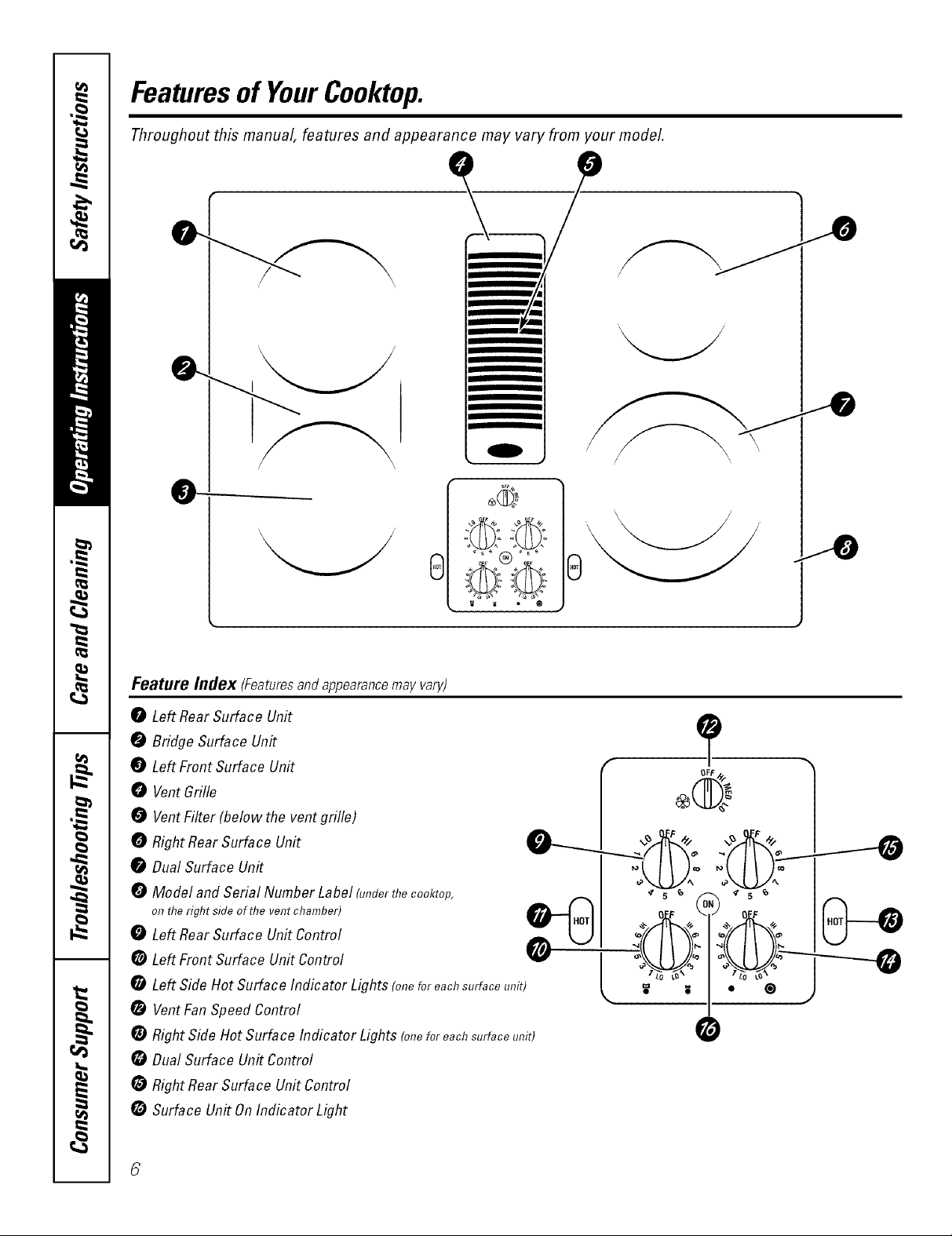
Featuresof YourCooktop.
Throughout this manual, features and appearance may vary from your model.
0
0
m
__
0
_ ®
Feature/lldex (Featuresand appearance may vary)
0 Left RearSurface Unit
0 Bridge Surface Unit
7
Left Front Surface Unit
0 VentGrille _
0
VentFilter(belowtheventgrille) -I = "_ I
oo.o,,._,o_oo.,r ;LU2:;LU!: I
0 Model and Serial Number Label(underthe cooktop, A _ I _ 5 _ _ _ s _ I
o,,the,ig,,t_i_eo_,,__,,_,,_,,b_,_ tB'h--I...II o_,_ o_'_ I(...')_f_
0 Left Rear Surface Unit Control _ U I _/1'_=£4'_ ICJ
*LeftSideHotSurfacelndicatorLights(o,,eforeochsurfoceunit) L '1"_'I ®L'_ J --
VentFanSpeed Control
RightSide Hot Surface Indicator Lights (oneforeachsurfaceunit) 0
DualSurface Un#Control
RightRear Surface Unit Control
Surface Un# On Indicator Light
i
Usingthe surface units. GEAppliances.com
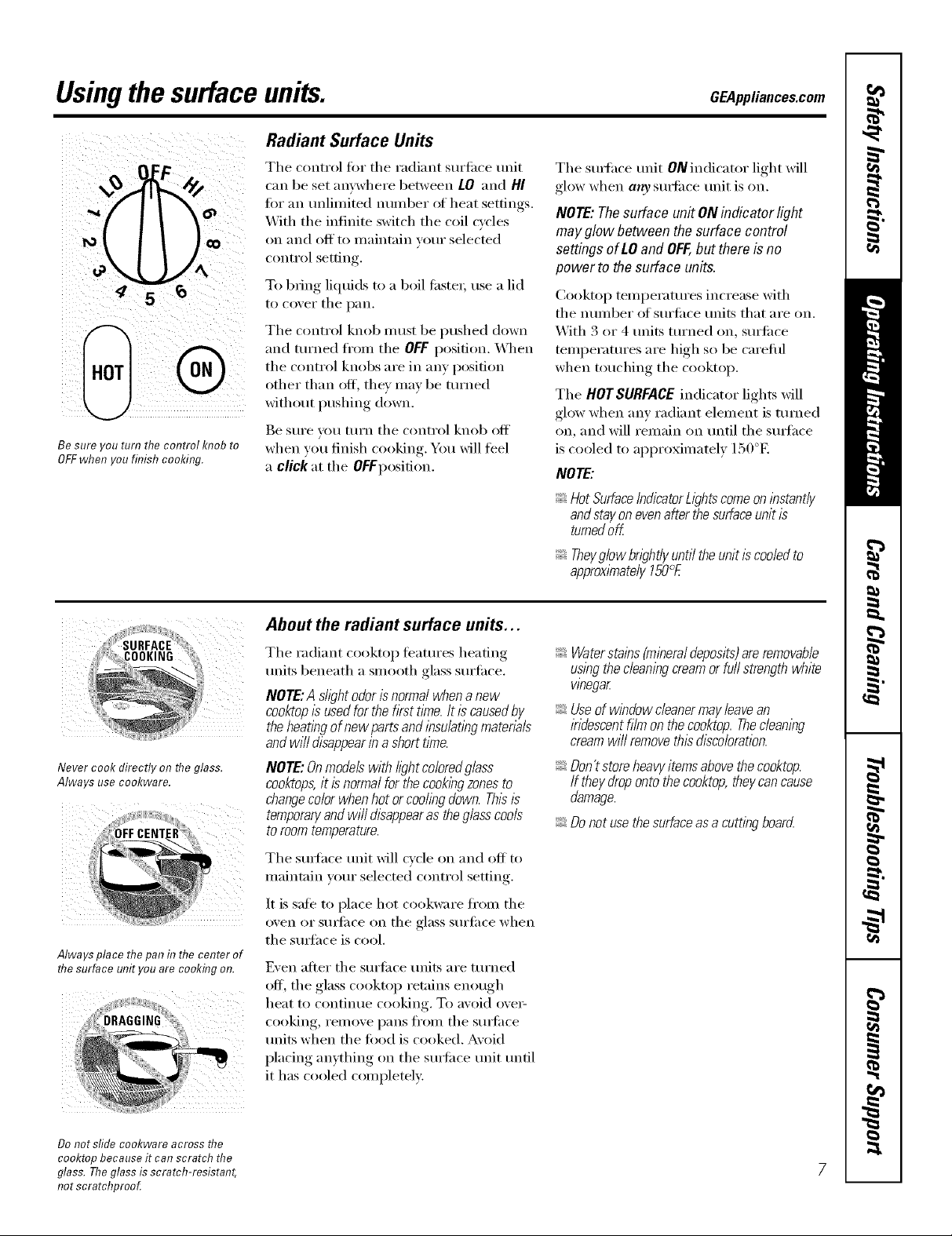
Radiant Surface Units
q
Be sure _ou turn me control KI?ODro
OFFwhen you finish cooking.
The control tor the radiant surfi_ce unit
can be set anywhere between LO and HI
tot an unlimited number of heat settings.
With tile infinite switch tile coil cycles
on and off to maintain your selected
control setting.
To bring liquids to a boil tilstei; use a lid
to cover tile pan.
The control knob must be pushed down
and turned fl'om tile OFFposition. _._l/ell
the control knobs are in any position
other than off, they may be turned
without pushing down.
Be sure you mrn tile control knob off
when you finish cooking. You will feel
a click at the Of Fposition.
Tile smthce unit ON indicator light will
glow when a,ty s/mfiace unit is on.
NOTE: Thesurface unit ON indicator light
may g/ow between the surface control
settings of LO and OFF,but there is no
powerto the surface units.
Cooktop temperatures increase with
tile nmnber _ff surti_ce milts that are on.
With 3 or 4 milts turned on, sm'fi_ce
temperatures are high so be carefifl
when touching the cooktop.
Tile HOTSURFACEindicator lights will
glow when any radiant element is turned
on, and will remain on until tile s/m'hce
is cooled to approximately 150°E
NOTE:
HotSurfaceIndicatorb)hts comeonlhstantly
andstayonevenafterthesurfaceunitis
turnedoff
Theyglowbwht/yuntiltheunitiscodedto
approximately150°E
Never cook directly on the glass.
Always use cookware.
Always place the pan in the center of
flTesurface unit you are cookfl}g on.
About the radiant surface units...
Tile radiant cooktop teatm'es heating
units beneath a smooth glass surfilce.
NOTE:A sh)htodorisnormalwhenanew
cooktopIsusedforthefkst time.Itiscausedby
theheatingofnewpartsandlhsu/atlhgmaterb/s
andwi//disappearin ashorttl_ne.
NOTE:Onmodelswithb)ht co/oredg/ass
cooktops,it isnormalforthecookbgzonesto
changecolorwhenhotorcodingdown.Thisis
temporaryandwi//disappearastheglasscools
toroomtemperature.
Tile smtace trait will cycle on and off to
maintain your selected control settin ,
It is sate to place hot cookware fl'om tile
o'_en ,(:,I"StlKlilce on tile glass Stllq'ilce when
the SUlqfhce is cool.
Even after tile surtiace units are turned
off, tile glass cooktop ret;fins enough
heat to contintle cooking. To avoid ovei _
cooking, remove pans ti'om the smti_ce
milts when tile load is cooked. Avoid
placing anything on the s/m'iace unit tmtil
it has cooled completely:
Waterstains(minera/deposits)areremovab/e
usingthecleaningcreamorfull strengthwhite
whegar
Useofwlhdowcleanermayleavean
indescentfilmonthecooktop.Thec/eamhg
creamwi//removethisdiscoloration.
Don'tstoreheavyitemsabovethecooktop.
If theydropontothecooktop,theycancause
damage.
Donotusethesurfaceasacuttinghoard
Do not sfide cookware across the
cooktop because it can scratch the
glass. Theglass is scratch-resistant,
not scratchproo_
Usingthe surface units.
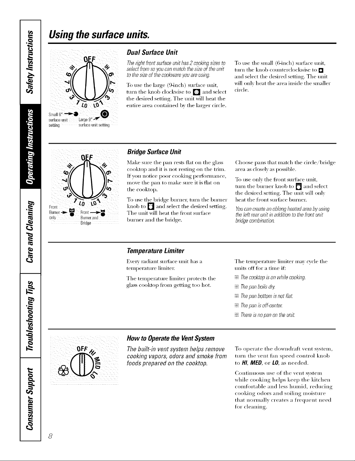
Dual Surface Unit
O[.FOF
tZo O:
setting surfaceunitsetting
0 F
F LO L_
Bru°ii/er-tb-_ Froltt._,,-_•
only Burner and
Bridge
Therightfrontsurfaceunithas2cooklbgsizesto
selectfromso youcanmatchthes/2eoftheunit
tothesl2eofthecookwareyouareusing.
To use the lmge (9-inch) suriime unit,
turn tile knob clockwise to [] and select
the desired setting. The unit will heat the
entire area contained by the linger circle.
Bridge Surface Un#
Make sure tile pan rests fiat on tile glass
cooktop and it is not resting on tile trim.
If you notice poor cooking pedimnance,
move the pan to make sure it is flat on
tile cooktop.
To use the bridge burnei; tunl the burner
knob to [] and select the desired setting.
The unit will heat the fi'ont suil'ilc'e
burner and tile bridge.
To use tile small (6-inch) surfi_ce unit,
ttli'n the knob counterclockwise to []
and select the desired setting. The unit
will only heat the area inside the smaller
circle.
Choose pans that match tile circle/bridge
area as closel) as possible.
To use onlx tile fl'ont stm'i_ce unit,
turn tile burner knob to [] and select
the desired setting. The unit will only
heat tile front surli_ce burner.
Youcan createan oblongheated areaby using
the left rear unit in addition to the front unit
bndgecomblbation.
Temperature Limiter
Every radiant surli_ce unit has a
temperature limited:
Tile temperature limiter protects tile
glass cooktop ti'om getting too hot.
How to Operate the Vent System
The built-in vent system helps remove
cooking vapors, odors and smoke from
foods prepared on the cooktop.
Tile temperature limiter may cycle tile
units off fin" a time if':
Thecooktopis on whilecooking.
Thepan boi/sdry
Thepan bottom is not f/a_
Thepan is off-center
Thereisno pan on the uniL
To operate tile downdrafl vent system
turn tile xent tim speed control knob
to HI, MED, or LO, as needed.
Continuous use of tile vent svstem
while cooking helps kee I) the kitchen
comtortable and less humid, reducing
cooking odors and soiling moisture
that normally creates a frequent need
tot cleaning.
8
Selectingtypesof cookware. CEA,,lia.ces.com
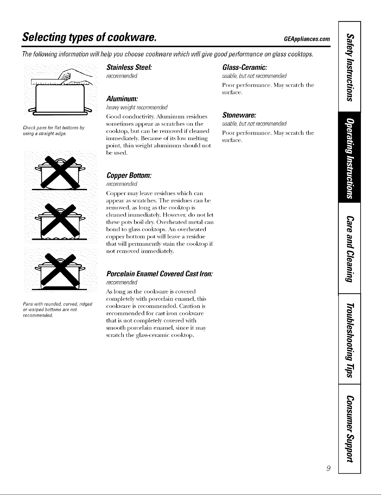
Thefollowing information will help you choose cookware which will give good performance on glass cooktops.
Stainless Steel'.
Aluminum:
heavy weight recommended
(;ood conducfivit): _Muminum residues
Check pans for flat bottoms by SOln etimes apl)ear as scratches on the
using a straight edge. cooktop, but can be removed if deaned
immediately: Because ofits low melting
point, thin weight aluminum should not
be used.
CopperBottom:
recommended
CoI_per may leave residues which ('_lil
appear as scratches. The residues can be
reI/loved, as long as the cooktop is
cleaned immediately. However; do not let
these pots boil dry: Overheated metal can
bond to glass cooktops. An overheated
COl)per bottom pot will leave a residue
that will pemmnently stain the cooktop if
not removed immediately.
Glass-Ceramic:
usable,butnotrecommended
Poor i_erfi)mmn('e. Ma) scratch the
StlI'J[il ce,
Stoneware:
usable, but not recommended
Poor perfimnance. Ma) scratch the
StlI'J[il ce.
Pans with rounded, curved, ridged
or warped bottoms are not
recommended.
Porcelain EnamelCoveredCastIron:
recommended
_&_long as the cookware is covered
complemly with porcelain enamel, this
cookware is recommended. Caution is
recommended for cast iron cookware
that is not completely covered with
smooth porcelain enamel, since it may
scratch the glass-ceramic cooktop.
9
Careand cleaning ofthe cooktop.
Be sure electrical power is off and all surfaces are cool before cleaning any part of the cooktop.
Vent System
Before cleaning the vent grille, be sure
the exhaust blower is turned off.
Do not use abrasive cleanex_. They will
damage the vent grille's finish.
To clean the vent grifle, remove it fl'om
the cooktop by lifting it up and off.
Wipe with a dmn I) cloth. If necessary,
the vent grille can be washed in the sink.
Use dishwashing liquid fi)r cleaning.
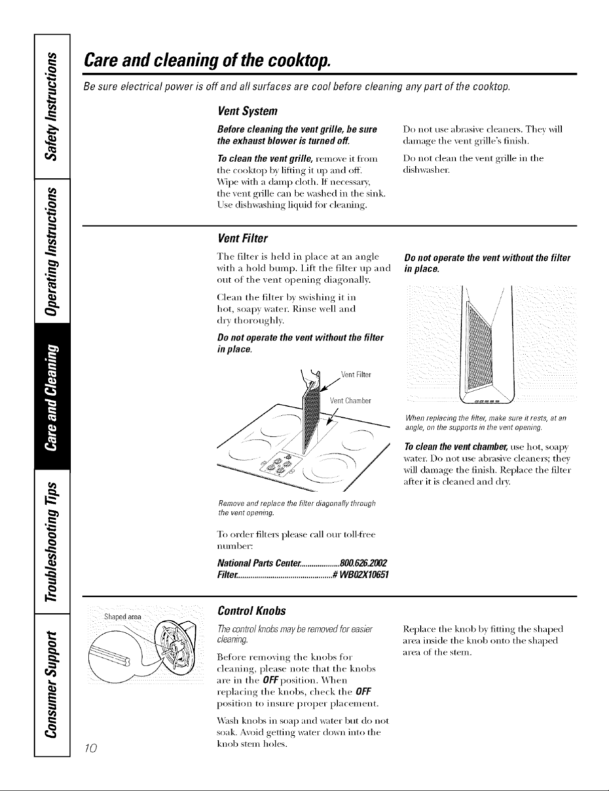
Vent Filter
The filter is held in place at an angle
with a hold bump. I,ilt the filter up and
out of the vent opening diagonally.
Clean the filter by swishing it in
hot, soapy water. Rinse well and
(h'x thoroughl).
Do not operate the vent without the filter
in place.
Vent Filter
VentChamber
Do not clean the vent grille in the
dishwashex:
Donot operatethe vent withoutthefilter
in place.
When replacing the filter, make sure it rests, at an
angle, on thesupports in the vent opening.
Toclean the ventchamber, use hot, soap)'
watet: Do not use abrasive cleane_; they
will damage the finish. Replace the filter
after it is cleaned and dry:
10
Shapedarea
Remove and replace flTefilter diagonally through
the vent opening.
To order filte_s please call our toll-ti'ee
n t/I/lbeI':
NationalPartsCenter....................800.626.2002
Filter................................................# WBO2X10651
Control Knobs
Thecontrolknobs maybe removedfor easier
cleanlbg.
Before removing the knobs fl)r
cleaning, please note that the knobs
are in the OFFposition. When
replacing the knobs, check the OFF
position to insure proper placement.
X_sh knobs in soap and water but do not
soak. A\oid getting water down into the
knob stem holes,
Replace the knob b) fitting the shaped
area inside the knob onto the shaped
area of the stem.

Cleaningthe glass cooktop. CEAppliancescom
Normal Daily Use Cleaning
Cleanyourcooktopafter
eachspill. Use CERAMA
BRYTE®CeramicCooktop
Cleaner.
ONLY use CEIL_dMA BRYTE _'Ceranfic
Cooktop Cleaner on the glass cooktop.
Other creams ma_ not be as eflectixe.
To inaii_taii_ and protect the SUlti_ce _ff
your glass cooktop, t011ow these steps:
[] Before using the cookto ) fi)r the
fi_t time, clean it with CEI_d'dA
BRYTE ')Ceralnic Cooktop Cleanei:
This helps protect the top and
inakes clean-up easiei:
[] Dail) tlse of CEl_z_d_/]_ BRYTE _:'
(2eramic ('xx)ktop Cleaner will help
kee I) the cooktop looking new.
, l
[] Shake the clealfing cream well.
Appl_ a few drops of CEI_dMA
BRYTE e_Ceramic Cooktop Cleaner
directly to the cooktop.
[] Use a p_}per towel or CEIL&MA
BRYTE _"Cleaning Pad fi)r Ceran]ic
Cooktops to clean the entire
cooktop StlI'J[ilce.
[] Use a dry cloth or paper towel
to relnove all cleaning residue.
No need to rinse.
NOTE: It/a very important that you DO NOT
heat the cooktop until it has been cleaned
thorough/_
iii/ / / /L ¸¸
( 2
Usea CERAMABRYTE*_Cleaning
Pad for Ceramic Co&tops or a
Scetch-Brite ®Multi-Purpose No
Scratch blue scrub pad.
TheCERAMABRYTE'*_Ceramic
Co&top Scraper and aft
recommended supplies are
available through our Parts Center.
See instructions under "ToOrder
Parts" section on next page.
NOTE:Do not use a duff or
nicked blade.
Burned-On Residue
WARNING:DAMAGEtoyourg/asssurface
mayoccurif youusescrubpadsotherthan
thepadbciudedwith yourcooktop.
[] Allow the cooktop to cool.
[] Spread a few drops of CER,AAMA
BRYTE _>(]eralnic Cooktop (]leaner
to the entire burned residue area.
Using the inchlded CEIL_MA
[]
BRYTE _>Cleanin- Pad for Ceramic
Cooktops, rub the residue area,
ali))lxing,, pressure as needed.
Heavy, Burned-On Residue
[] Allow the cooktop to cool.
[] Use a single-edge razor blade
scraper at approxinmtely a 45 °
angle against the glass surface and
scrape the soil. It will be necessary
to apply pressure to the razor
scraper in order to remove the
residue,
[] If any residue renmins, repeat the
steps listed above as needed.
[] For additional protection, after all
residue has been relnoxed, polish
the entire surfi_ce with CERAMA
BRYTE ') (_eralnic Cooktop Cleaner
and a paper towel.
[] After scraping with the razor
scraper, spread a few drops of
(%l_d'dA BRYTE <'_Ceramic
()_oktop Cleaner to the entire
burned residue area. Use the
CERAMA BRYTE ') Cleaning Pad
to remove any renmilfing residue.
[] For additional protection, alter all
residue has been relnoxed, polish
the entire surtace with CERAMA
BRYTE ')Ceralnic Cooktop Cleaner
and a paper towel.
11

Cleaningtheglass cooktop.
Metal Marks and Scratches
[] Be careflll not to slide pots and
pans across your cooktop. It will
leave metal markings on the
cooktop S/lI'J[_lce.
These marks are remowd)le using
the CERAMA BRYTE (')Ceramic
Cookto I) Cleaner with the
CERAMA BRYTE 6) Cleaning Pad
ti_r Ceramic Cooktoi)s.
[] If pots with a thin oxerla) of
aluminum or COl)per are allowed
to boil dr):, the overlay may leave
black discoloration on the
cooktop.
Glasssurface--potential forpermanent damage.
Our testing shows that if
you are cooking high sugar
mixtures such as jelly or
fudge and have a spillover,
it can cause permanent
damage to the glass surface
unless the spillover is
immediately removed.
Damage from Sugary Spills and Melted Plastic
[] Turn off all surthce units. Remove
hot pans.
[] Wearing an oven mitt:
a. Use a single-edge razor blade
scraper (CEI__MA BRYTE :
Ceramic Cooktop Scraper) to
move the spill to a cool area
on the cooktop.
b. Remove the spill with
paper towels.
This should be removed immediately
before heating again or the
discoloration may be permanent.
WARNING: Carefullycheck the bottom
of pans for roughness that would scratch
the cooktop.
[] An) remaining spillover should be
left until the surfi_ce of the cooktop
has cooled.
] Don't use the surtace units again
until all of the residue has been
completely removed.
NOTE: If pitting or indentation lb the glass
surface has already occurred, the cooktop
glass will have to be replaced In this case,
service wifl be necessarg
12
To Order Parts
To order CERAMA BRYTE _ Ceramic
Cooktop Cleaner and the cooktop
scrape_; please call our toll-free number:
National Parts Center 800.626.2002
CERAMABRYTE®
CeramicCooktopCleaner.... # WXIOX300
CERAMABRYTE®
CeramicCooktopScraper . .# WXI OX0302
Kit ...................... # WB64XS027
(Kitincludescreamandrazorscraper)
CERAMABRYTE® CleaningPadsfor
CeramicCooktops........... #WXTOX350
Radiant
Ilnstallation
nstruct ons
I If you have questions, call 800.GE.CARES (800.432.2737) or visit our Website at: GEAppliances.com
Downdraft Cooktop
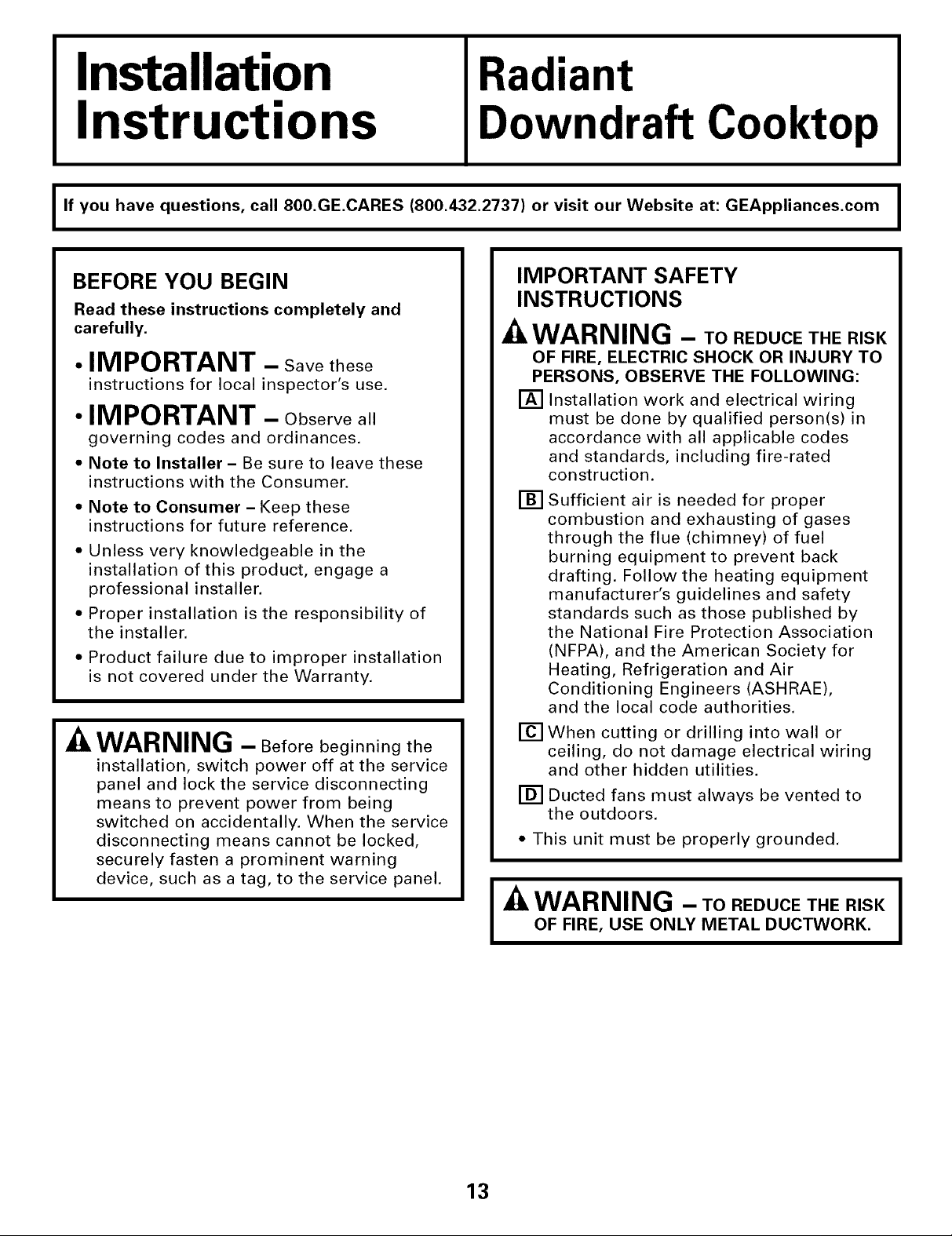
BEFORE YOU BEGIN
Read these instructions completely and
carefully.
• IMPORTANT - Savethese
instructions for local inspector's use.
• IMPORTANT - Observeall
governing codes and ordinances.
• Note to Installer - Be sure to leave these
instructions with the Consumer.
• Note to Consumer - Keep these
instructions for future reference.
• Unless very knowledgeable in the
installation of this product, engage a
professional installer.
• Proper installation is the responsibility of
the installer.
• Product failure due to improper installation
is not covered under the Warranty.
WARNING - Beforebeginning the
installation, switch power off at the service
panel and lock the service disconnecting
means to prevent power from being
switched on accidentally. When the service
disconnecting means cannot be locked,
securely fasten a prominent warning
device, such as a tag, to the service panel.
IMPORTANT SAFETY
INSTRUCTIONS
WARNING - ToREOUCETHERISK
OF FIRE, ELECTRIC SHOCK OR INJURY TO
PERSONS, OBSERVE THE FOLLOWING:
[] Installation work and electrical wiring
must be done by qualified person(s) in
accordance with all applicable codes
and standards, including fire-rated
construction.
[]
Sufficient air is needed for proper
combustion and exhausting of gases
through the flue (chimney) of fuel
burning equipment to prevent back
drafting. Follow the heating equipment
manufacturer's guidelines and safety
standards such as those published by
the National Fire Protection Association
(NFPA), and the American Society for
Heating, Refrigeration and Air
Conditioning Engineers (ASHRAE),
and the local code authorities.
[]
When cutting or drilling into wall or
ceiling, do not damage electrical wiring
and other hidden utilities.
[] Ducted fans must always be vented to
the outdoors.
• This unit must be properly grounded.
I
OF FIRE, USE ONLY METAL DUCTWORK.
I_k WARNING - ToREOUCETHERISKI
13
I
Installation Instructions
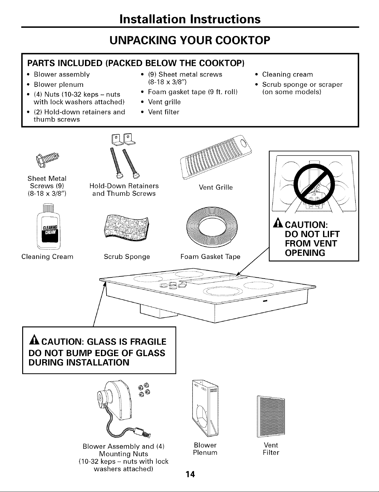
UNPACKING YOUR COOKTOP
PARTS INCLUDED (PACKED BELOW THE COOKTOP)
* Blower assembly
* Blower plenum
• (4) Nuts (10-32 keps- nuts
with lock washers attached)
• (2) Hold-down retainers and
thumb screws
Sheet Metal
Screws (9)
(8-18 x 3/8")
Hold-Down Retainers
and Thumb Screws
• (9) Sheet metal screws
(8-18 x 3/8")
• Foam gasket tape (9 ft. roll)
• Vent grille
• Vent filter
Vent Grille
• Cleaning cream
• Scrub sponge or scraper
(on some models)
Cleaning Cream
A
Scrub Sponge
• ILCAUTION: GLASS IS FRAGILE
DO NOT BUMP EDGE OF GLASS
DURING INSTALLATION
O
Foam Gasket Tape
-_ CAUTION:
DO NOT LIFT
FROM VENT
OPENING
Blower Assembly and (4)
Mounting Nuts
(10-32 keps - nuts with lock
washers attached)
Blower Vent
Plenum Filter
14
Installation Instructions
PREPARATION
TOOLS AND MATERIALS
YOU WILL NEED
• Saw
• Flat blade screwdriver
• Electrician's pliers
• Duct tape
• Measuring tape or scale
• Carpenter's square
• 7/16" wrench or socket set
• Drill and drill bit
• Sheet metal screws
• Junction box*
• 3/4" flexible conduit*
• Electrical wire per local code*
• Wire nuts*
• Duct work
*NOTE: Electrical installation kit JXCK89
may be ordered separately and includes all
the parts necessary to connect the cooktop
to typical rough-in wiring.
-A CAUTION: FOR PERSONAL SAFETY,
REMOVE HOUSE FUSE OR CIRCUIT
BREAKER BEFORE BEGINNING
INSTALLATION.
ELECTRICAL REQUIREMENTS
This appliance must be supplied with the proper
voltage and frequency, as listed in these Installation
Instructions, and connected to an individual,
properly grounded branch circuit, protected
by a 40-amp circuit breaker or time delay fuses.
All wire connections must be made in accordance
with local codes and properly insulated. Check with
your local utility for governing electrical codes and
ordinances. In the absence of local electrical codes,
the National Electrical Code, ANSIiNFPA No. 70 -
Latest Edition, governing electric range installations,
must be followed.
A copy of the National Electrical Code can be
obtained by writing to:
National Fire Protection Association
Batterymarch Park
Quincy, MA 02260
Effective January 1, 1996, the National Electrical
Code requires that new, but not existing,
construction utilize a four-conductor connection to
an electric range. When installing an electric range
in new construction, follow the instructions in NEW
CONSTRUCTION AND FOUR-CONDUCTOR
BRANCH CIRCUIT CONNECTION.
You must use a three-wire, single-phase AC
208Y/120 Volt or 240/120 Volt, 60 Hertz electrical
system with separate ground. If you connect to
aluminum wiring, properly installed connectors
approved for use with aluminum wiring must
be used.
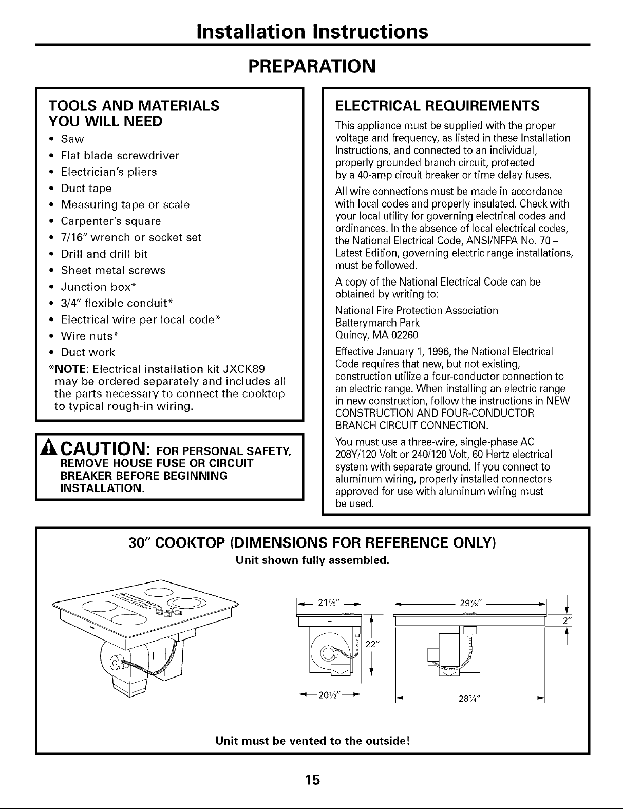
30" COOKTOP (DIMENSIONS FOR REFERENCE ONLY)
Unit shown fully assembled.
21%"
22 tt
T
_ 201_2"_
Unit must be vented to the outside!
297/8"
283/4" =
15
2 H
A
Installation Instructions
CABINET PREPARATION
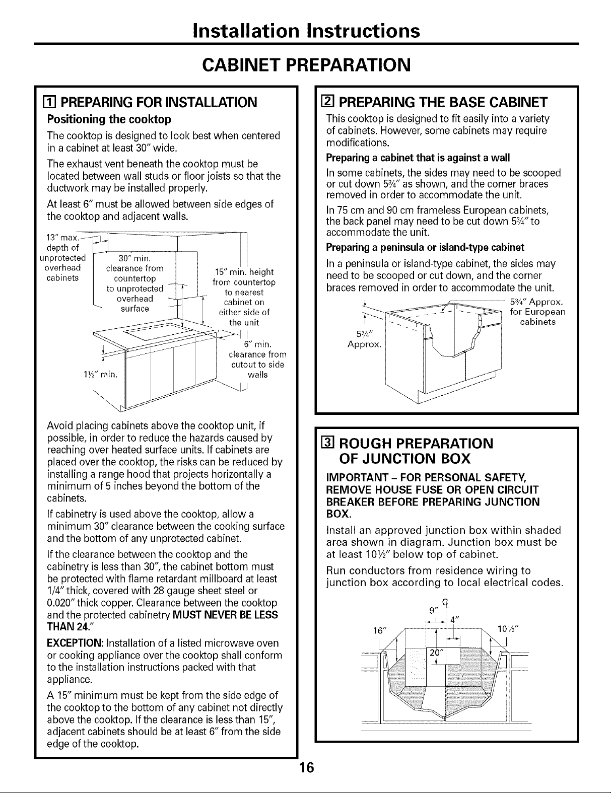
[] PREPARING FOR INSTALLATION
Positioning the cooktop
The cooktop is designed to look best when centered
in acabinet at least 30" wide.
The exhaust vent beneath the cooktop must be
located between wall studs or floor joists so that the
ductwork may be installed properly.
At least 6" must be allowed between side edges of
the cooktop and adjacent walls.
13" max._. 4
depth of
unprotected 30" min.
overhead clearance from
cabinets countertop
to unprotected
overhead
surface
11/2"min.
15" min. height
from countertop
to nearest
cabinet on
either side of
the unit
J
6" min.
clearance from
cutout to side
walls
[] PREPARING THE BASE CABINET
This cooktop is designed to fit easily into a variety
of cabinets. However, some cabinets may require
modifications.
Preparing a cabinet that is against a wall
In some cabinets, the sides may need to be scooped
or cut down 5_" as shown, and the corner braces
removed in order to accommodate the unit.
In 75 cm and 90 cm frameless European cabinets,
the back panel may need to be cut down 5¾"to
accommodate the unit.
Preparing a peninsula or island-type cabinet
In a peninsula or island-type cabinet, the sides may
need to be scooped or cut down, and the corner
braces removed in order to accommodate the unit.
53/4"Approx.
for European
cabinets
Approx.
Avoid placing cabinets above the cooktop unit, if
possible, in order to reduce the hazards caused by
reaching over heated surface units. If cabinets are
placed over the cooktop, the risks can be reduced by
installing a range hood that projects horizontally a
minimum of 5 inches beyond the bottom of the
cabinets.
If cabinetry is used above the cooktop, allow a
minimum 30" clearance between the cooking surface
and the bottom of any unprotected cabinet.
If the clearance between the cooktop and the
cabinetry is less than 30", the cabinet bottom must
be protected with flame retardant millboard at least
1/4" thick, covered with 28 gauge sheet steel or
0.020" thick copper. Clearance between the cooktop
and the protected cabinetry MUST NEVER BE LESS
THAN 24."
EXCEPTION: Installation of a listed microwave oven
or cooking appliance over the cooktop shall conform
to the installation instructions packed with that
appliance.
A 15" minimum must be kept from the side edge of
the cooktop to the bottom of any cabinet not directly
above the cooktop. If the clearance is less than 15",
adjacent cabinets should be at least 6" from the side
edge of the cooktop.
[] ROUGH PREPARATION
OF JUNCTION BOX
IMPORTANT - FOR PERSONAL SAFETY,
REMOVE HOUSE FUSE OR OPEN CIRCUIT
BREAKER BEFORE PREPARING JUNCTION
BOX.
Install an approved junction box within shaded
area shown in diagram. Junction box must be
at least 101/2"below top of cabinet.
Run conductors from residence wiring to
junction box according to local electrical codes.
6

Installation Instructions
CABINET PREPARATION CUTOUTS
[] PREPARING THE COUNTERTOP
The countertop must have a deep flat surface
to accommodate the cooktop and the vent.
Countertops with a rolled front edge and
backsplash may not provide the flat surface
area required.
Clearance between inside front of cabinet and
rear of countertop cutout must be 20%" in
order to accommodate cooktop depth.
2%" Min. 1%" Min.
A 1/2" wide flat area is required around the
edge of opening for support of the unit. The
cooktop unit must be level and sit squarely
into countertop opening.
Carefully cut countertop opening according to
the dimensions shown in the illustration. Be
sure that opening is cut squarely, with sides
parallel to each other and rear exactly
perpendicular to sides.
20%"
17_" Min.
[] PREPARINGFORDUCTWORK
NOTE: Ductwork MUST be vented to outside. DO
NOT vent into a wall, ceiling, crawlspace, attic or any
concealed space.
Cut hole in cabinet wall or floor as appropriate for
your installation. Make sure exhaust duct is located
between wall studs or floor joists.
NOTE: When cutting or drilling into wall or ceiling,
do not damage electrical wiring and other hidden
utilities.
91/3"
183/4"
Rear Wall Venting
Downward Venting
[] BLOWERTO DUCTWORK ALIGNMENT
In general, the use of flexible ducting is discouraged
because it can cause severely restricted airflow.
However, if the blower outlet and the floor or wall
duct location do NOT align well, then flexible METAL
ducting can be used to adapt to an offset. Good
alignment without use of flexible ducting is best.
NOTE:
• Do not exceed the maximum recommended offset
of 6".
* Do not allow the flexible ducting to kink or collapse.
* Do stretch the flexible ducting as much as possible
to eliminate as much of the corrugation as possible.
Centtejline_ I
Ce_F:_it e t
_6"Max._ i
Bottom Venting Back Venting
(Requires 31¼" x 10")
A 31A'x 10" rectangle to 6" round transition duct is
available at your local building supply store.
NOTE: Illustrations are for planning purposes only.
17
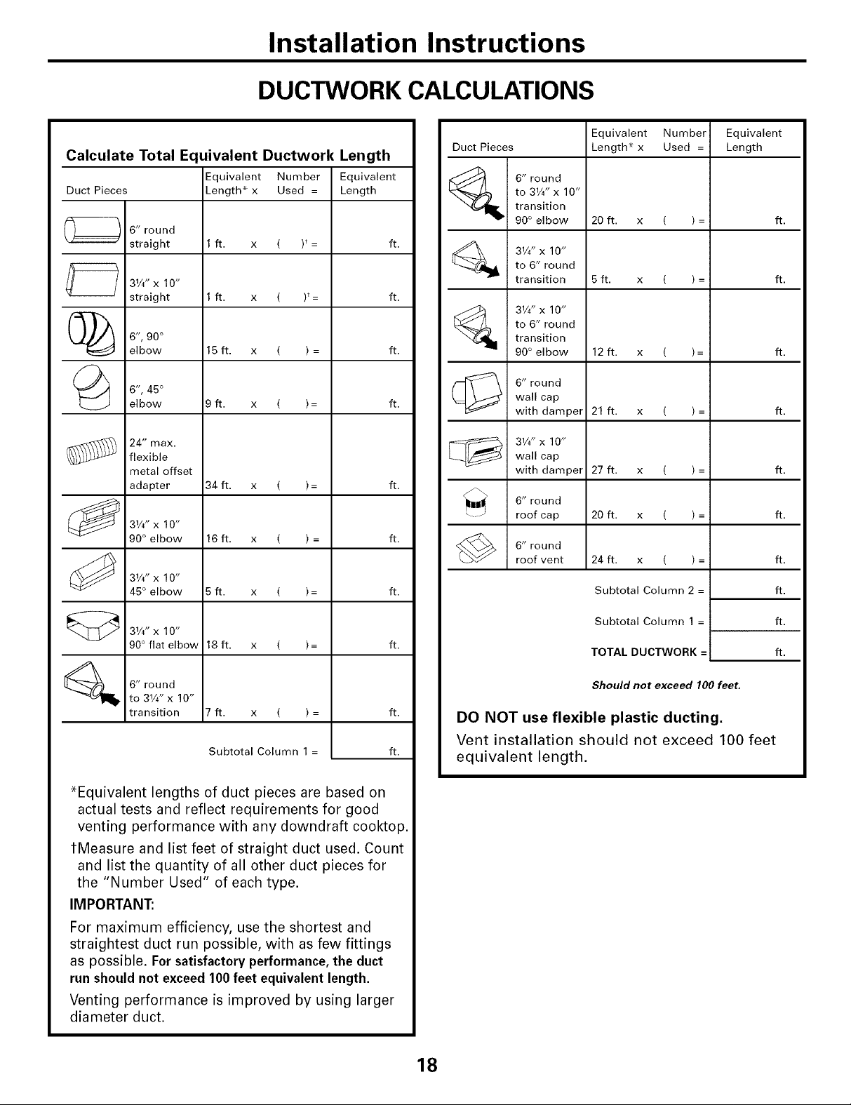
Calculate Total E(
Duct Pieces
6" round
straight
31/4"x 10"
straight
Installation Instructions
DUCTWORK CALCULATIONS
uivalent Ductwork Length
Equivalent Number
Length* x Used =
1ft. x ( )*=
1ft. x ( F=
Equivalent
Length
Equivalent Number Equivalent
Duct Pieces Length* x Used = Length
to 31/4" x 10"
6" round
transition
90° elbow 20 ft. x ( ) = ft.
ft.
ft.
31/4"x 10"
to 6" round
transition 5 ft. x ( ) = ft.
C_ 6", 90 °
elbow
6", 45 °
elbow
24" max.
flexible
metal offset
adapter
31/4,,X10, "
90° elbow
31/4" X 10"
45° elbow
31/4,,X10, "
90° flat elbow
6" round
to 31/4" x 10"
transition
15 ft. x ( ) =
9ft. x ( )=
34 ft. x ( )=
16 ft. x ( ) =
5ft. x ( )=
18 ft. x ( )=
7ft. x ( )=
Subtotal Column 1 =
[_ 31/4" X 10"
ft.
ft.
ft.
ft.
ft.
ft.
ft.
DO NOT use flexible plastic ducting.
to 6" round
transition
90° elbow 12 ft. x ( )= ft.
wall cap
6" round
with damper 21 ft. x ( ) = ft.
31/4" X 10"wall cap
with damper 27 ft. x ( ) = ft.
6" round
roof cap 20 ft. x ( ) = ft.
6" round
roof vent
24 ft. x ( )=
Subtotal Column 2 =
Subtotal Column 1 =
TOTAL DUCTWORK =
Should not exceed 100 feet,
ft,
ft.
ft.
ft.
Vent installation should not exceed 100 feet
ft.
equivalent length.
*Equivalent lengths of duct pieces are based on
actual tests and reflect requirements for good
venting performance with any downdraft cooktop.
tMeasure and list feet of straight duct used. Count
and list the quantity of all other duct pieces for
the "Number Used" of each type.
IMPORTANT:
For maximum efficiency, use the shortest and
straightest duct run possible, with as few fittings
as possible. For satisfactory performance, the duct
run should not exceed 100feet equivalent length.
Venting performance is improved by using larger
diameter duct.
18
Installation Instructions
EXHAUST BLOWER RATINGS
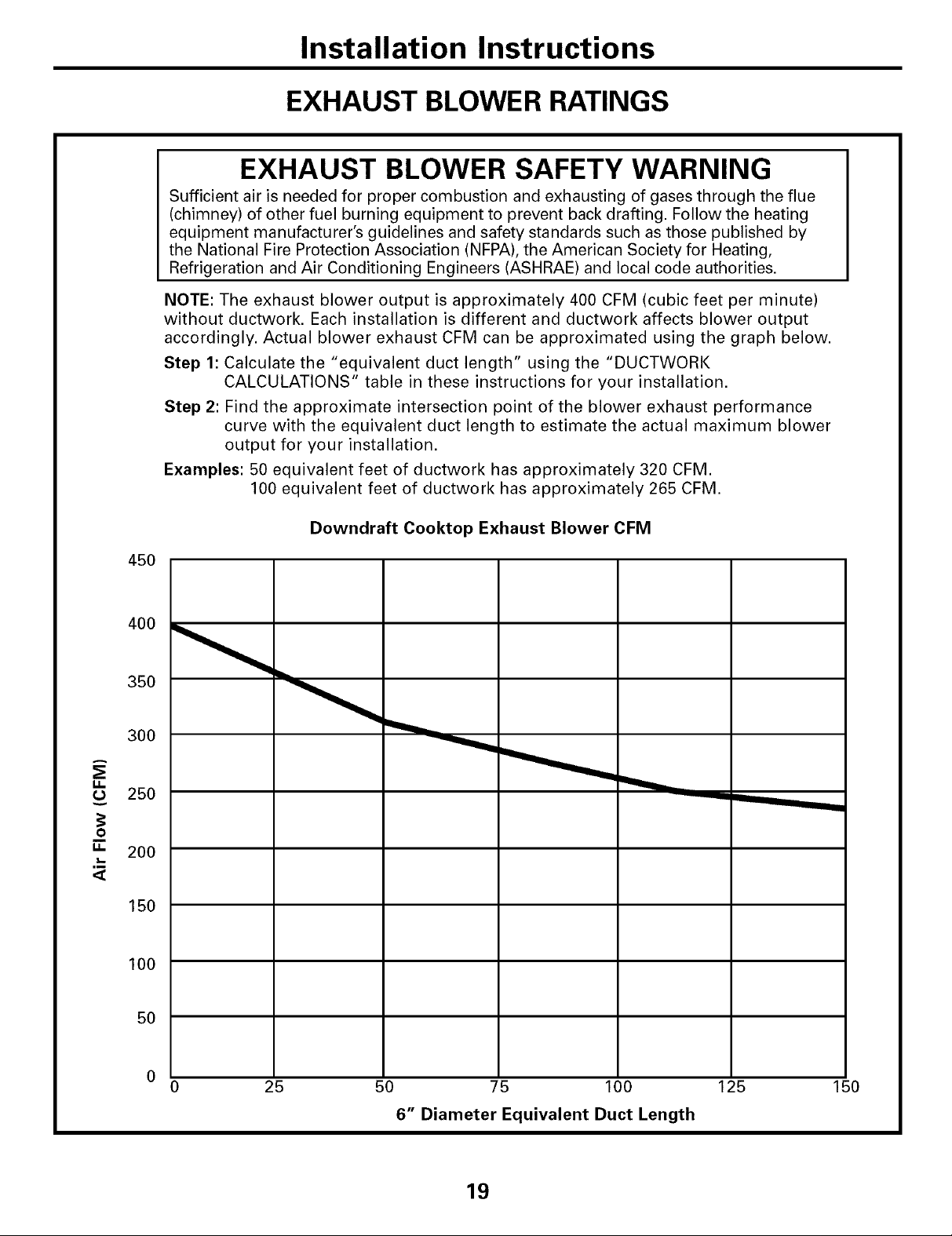
EXHAUST BLOWER SAFETY WARNING
Sufficient air is needed for proper combustion and exhausting of gases through the flue
(chimney) of other fuel burning equipment to prevent back drafting. Follow the heating
equipment manufacturer's guidelines and safety standards such as those published by
the National Fire Protection Association (NFPA), the American Society for Heating,
Refrigeration and Air Conditioning Engineers (ASHRAE) and local code authorities.
NOTE: The exhaust blower output is approximately 400 CFM (cubic feet per minute)
without ductwork. Each installation is different and ductwork affects blower output
accordingly. Actual blower exhaust CFM can be approximated using the graph below.
Step 1: Calculate the "equivalent duct length" using the "DUCTWORK
CALCULATIONS" table in these instructions for your installation.
Step 2: Find the approximate intersection point of the blower exhaust performance
curve with the equivalent duct length to estimate the actual maximum blower
output for your installation.
Examples: 50 equivalent feet of ductwork has approximately 320 CFM.
100 equivalent feet of ductwork has approximately 265 CFM.
g.
g.
,m
<[
Downdraft Cooktop Exhaust Blower CFM
45O
350
300
25O
O
200
150
100
50
25 50 75 100 125
6" Diameter Equivalent Duct Length
19
150
Installation Instructions
DUCTWORK INSTALLATION
(Note: For planning purposes only.)
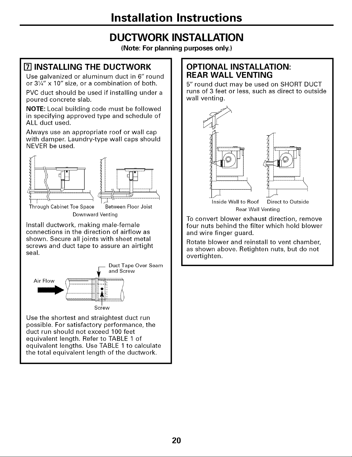
[] INSTALLING THE DUCTWORK
Use galvanized or aluminum duct in 6" round
or 31/4" x 10" size, or a combination of both.
PVC duct should be used if installing under a
poured concrete slab.
NOTE: Local building code must be followed
in specifying approved type and schedule of
ALL duct used.
Always use an appropriate roof or wall cap
with damper. Laundry-type wall caps should
NEVER be used.
Through Cabinet Toe Space
Downward Venting
Install ductwork, making male-female
connections in the direction of airflow as
shown. Secure all joints with sheet metal
screws and duct tape to assure an airtight
seal.
Between Floor Joist
Duct Tape Over Seam
-- and Screw
OPTIONAL INSTALLATION:
REAR WALL VENTING
5" round duct may be used on SHORT DUCT
runs of 3 feet or less, such as direct to outside
wall venting.
Inside Wall to Roof Direct to Outside
Rear Wall Venting
To convert blower exhaust direction, remove
four nuts behind the filter which hold blower
and wire finger guard.
Rotate blower and reinstall to vent chamber,
as shown above. Retighten nuts, but do not
overtighten.
Screw
Use the shortest and straightest duct run
possible. For satisfactory performance, the
duct run should not exceed 100 feet
equivalent length. Refer to TABLE 1 of
equivalent lengths. Use TABLE 1 to calculate
the total equivalent length of the ductwork.
20
 Loading...