

Page 1
GE Appliances
Specification Revised 6/99
JP380BVBB - GE 30" Patio Grill with Downdraft Venting System
Built-In Downdraft Modular Cooktop
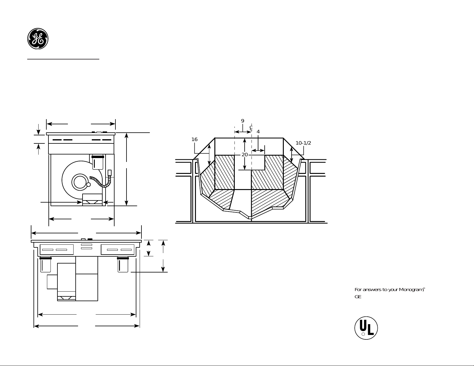
Dimensions (in inches)
Built-In Downdraft Modular Cooktop Cabinet
Dimensions (in inches)
21-9/16
3
19
6"
Dia.
20-1/2
Receptacle Location: Install an approved
junction box within shaded area shown in
diagram. Junction box must be at least 10-1/2"
below top of cabinet.
Installation Information: Before installing,
consult installation instructions packed with
product for current dimensional data.
28-7/8
27-1/2
29-7/8
12-1/4
6
,
20
9
4
10-1/2
16
C
L
For answers to your Monogram,
®
GE Profile Performance Series,
™
GE Profile™or GE appliance questions, call
GE Answer Center®service, 800.626.2000.
R
Listed by
Underwriters
Laboratories
Page 2
GE Appliances
Specification Revised 6/99
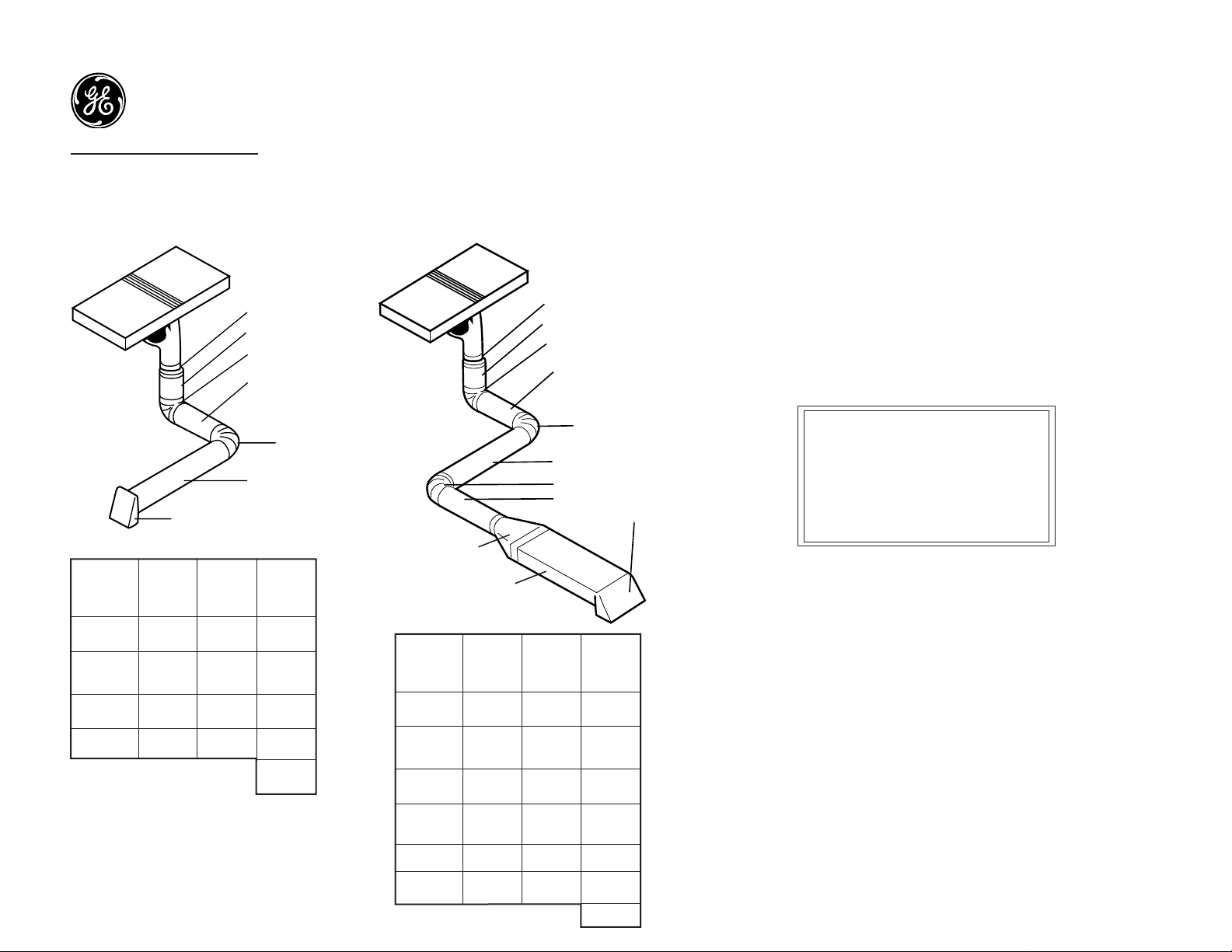
5" to 6" Transition
2' of 6" Round
6" Elbow
4' of 6" Round
6" Elbow
6' of 6" Round
6" Wall Cap
5" to 6" Transition
6" to 3-1/4" x 10" Transition
2' of 6" Round
6" Elbow
4' of 6" Round
4' of 6" Round
3-1/4" x 10" Wall Cap
6" Elbow
6' of 6" Round
6" Elbow
10" to 3-1/4" x 10" Straight
Duct Fitting
Equivalent
Length
Number
of Fittings
Total
Equivalent
Length of
Fittings
5” to 6”
Transition
6” Straight
6” Elbow
6” Wall Cap
1
1
5
28
1
2+4+6=12
2
1
1
12
10
28
51
Duct Fitting
Equivalent
Length
Number
of Fittings
Total
Equivalent
Length of
Fittings
5” to 6”
Transition
6” Straight
6” Elbow
6” to
3-1/4”x 10”
Transition
1
1
5
1
1
2+4+6+4=16
3
1
1
16
15
1
63
3-1/4”x 10”
Straight
1
10 10
3-1/4”x 10”
Wall Cap
20
120
JP380BV—GE 30" Patio Grill with Downdraft Venting System
Venting Duct Information
Install the Ductwork
• Ducting must conform to local code materials and “make-up”
requirements–300 CFM minimum.
• IMPORTANT: Save for local electrical inspector’s use.
• Ducting a cooktop is easy but critical for proper performance.
• After reading these instruction, plan the duct run.
• Use the “Duct Length Chart” to find the equivalent length of the run.
• Shift the blower to “high range” if indicated (done by snapping the
“restricter ring” out of the blower inlet). Be sure blower is not running.
• Install the duct hardware.
IMPORTANT
Total allowance duct system is:
90’ with 6” round wall cap
80’ with 3-1/4” x 10” wall cap
Low range is up to 60’
High range is 61’ to 90’
General Considerations:
1. Use 6” diameter round or 3-1/4” x 10” rectangular only.
2. Usa a 5” to 6” transition (or a 5” round to 3-1/4” x 10” rectangular transition)
at the blower outlet. The number of additional elbows or transitions in the
system should be limited to three.
3. Use quality metal duct of at least 26 gauge galvanized or 24 gauge
aluminum. Inferior quality pipe and fittings can cause up to twice the
restriction shown and is a poor value. Local codes may require a heavier
gauge material or restrict PVC.
4. Distance between adjacent fittings (elbows, transitions, etc.) should be at
least 18”. The further the better. Closer distance promotes turbulence which
reduces airflow.
5. Handmade crimps are likely to cause restrictions.
6. If an alternate wall or roof cap is used, be certain duct size is not
reduced, and that there is a backdraft damper. It is best to use listed caps
to be certain of proper performance.
7. Thermal breaks: In areas of extreme cold weather, it may be necessary to
provide a short length of nonmetallic duct as close to the wall as possible,
to prevent conduction along the metal duct.
8. High altitude installations: It is advisable to reduce allowable duct run by 20%.
9. Follow the duct calculation carefully for best performance and satisfaction.
Page 3

GE Appliances
Specification Revised 6/99
JP380BVBB - GE 30" Patio Grill with Downdraft Venting System
Cutout Dimensions (in inches)
25
1-7/8"
MIN. Required*
20-5/8
28-7/8
*U.L. Requirement.
Note: A 6" minimum spacing to adjacent side wall is required
Note: In some cabinets, the sides may need to be scooped or cut down 2" as shown and the corner
braces removed in order to accommodate the cooktop.
Wall Installation: Wall installations require 25" countertop depth. When cabinet is flush against
the wall, the fan housing can be rotated to the horizontal position for direct venting through rear
wall. Make a countertop cutout that is centered in the range cabinet according to unit dimensions
and installation type. Duct hole is positioned in back of cabinet for through-the-wall ducting.
Peninsula or Island Installation: For peninsula or island installation, a minimum 26" countertop
depth is suggested. Blower should be in vertical position. Island or peninsula cabinets may require
adjustment in cutout depth and/or location within the width dimensions. Duct hole is positioned in
bottom of cabinet for island or peninsula installation.
Slab Installation: For peninsula or island installation and rear wall ducting, PVC duct or locallyapproved piping should be used if installing under a poured concrete slab.
Installing the Ductwork: Use minimum 26-gauge
galvanized or 24-gauge aluminum duct in 6" round
or 3-1/4" x 10" size, or combination of both.
PVC duct or locally approved piping should
be used if installing under a poured
concrete slab.
Preparing the Cabinet for Installation
2" Approx.
5" Approx.
for European
cabinets
9-3/8
7-9/16
Downward venting
(in inches)
9-3/8
15-3/4
Rear wall venting (in inches)
For answers to your Monogram,
®
GE Profile Performance Series,
™
GE Profile™or GE appliance questions, call
GE Answer Center®service, 800.626.2000.
R
Listed by
Underwriters
Laboratories
Page 4

GE Appliances
Specification Revised 6/99
JP380BVBB - GE 30" Patio Grill with Downdraft Venting System
Venting Options
Inside Wall
Through Roof
Note: Ductwork must be vented to outside. Do
not vent into a wall, ceiling, crawlspace, attic or
any concealed space. Always use an appropriate
roof or wall cap with damper. Laundry-type wall
caps should never be used. For maximum efficiency use, the shortest and straightest duct
run possible, with as few fittings as possible. For
satisfactory performance, the duct run
should not exceed 100 feet equivalent length.
Refer to the table of equivalent lengths for various
duct configurations.
Installation Information: Before installing,
consult installation instructionspacked with
product for current dimensional data.
Direct to Outside
Straight Duct
Between the Floor Joists
Through the Cabinet Toe Space
For answers to your Monogram,
®
GE Profile Performance Series,
™
GE Profile™or GE appliance questions, call
GE Answer Center®service, 800.626.2000.
R
Listed by
Underwriters
Laboratories
KW Rating
240V 8.0
Breaker Size
40 Amps
†
†
Note: Check local codes for required breaker size
Page 5

GE Appliances
Specification Revised 6/99
JP380BVBB - GE 30" Patio Grill with Downdraft Venting System
L
0
HI
MED
L
0
HI
MED
Features and Benefits
•Black on black Model
• 30" Patio Grill
• Fixed Grill Elements On Each Side
• Infinite Heat Rotary Controls
• Powerful Downdraft Venting System
• Heating Element “ON” Indicator Light
• Black Porcelain-Enameled Cooktop
• Single-Speed Downdraft Vent Fan
 Loading...