

Page 1
C
GE Consumer Home Services Training
TECHNICAL SERVICE GUIDE
Electronic Touch Control
&
Electric Manual Control
Cooktops
MODEL SERIES:
Electronic: JP938
JP968
Electric: JP340
JP350
JP930
JP960
PUB # 31-9070 01/01
Page 2

!
IMPORTANT SAFETY NOTICE
The information in this service guide is intended for use by
individuals possessing adequate backgrounds of electrical,
electronic, and mechanical experience. Any attempt to repair a
major appliance may result in personal injury and property
damage. The manufacturer or seller cannot be responsible for the
interpretation of this information, nor can it assume any liability in
connection with its use.
WARNING
To avoid personal injury , disconnect power before servicing this
product. If electrical power is required for diagnosis or test
purposes, disconnect the power immediately after performing the
necessary checks.
RECONNECT ALL GROUNDING DEVICES
If grounding wires, screws, straps, clips, nuts, or washers used
to complete a path to ground are removed for service, they must
be returned to their original position and properly fastened.
GE Consumer Home Services Training
Technical Service Guide
Copyright © 2000
All rights reserved. This service guide may not be reproduced in whole or in part
in any form without written permission from the General Electric Company.
Page 3

Table of Contents
Table of Contents
Introduction . . . . . . . . . . . . . . . . . . . . . . . . . . . . . . . . . . . . . . . . . . . . . . . . . . . . . 2
Installation . . . . . . . . . . . . . . . . . . . . . . . . . . . . . . . . . . . . . . . . . . . . . . . . . . . . . . 3
Specifications and Nomenclature5 . . . . . . . . . . . . . . . . . . . . . . . . . . . . . . . . . . 5
Warranty Information. . . . . . . . . . . . . . . . . . . . . . . . . . . . . . . . . . . . . . . . . . . . . . 6
Cooktop Features and Controls . . . . . . . . . . . . . . . . . . . . . . . . . . . . . . . . . . . . 7
Diagnostics . . . . . . . . . . . . . . . . . . . . . . . . . . . . . . . . . . . . . . . . . . . . . . . . . . . . 12
Mechanical Disassembly . . . . . . . . . . . . . . . . . . . . . . . . . . . . . . . . . . . . . . . . . 18
Component and Connector Locator Views . . . . . . . . . . . . . . . . . . . . . . . . . . 27
Schematics . . . . . . . . . . . . . . . . . . . . . . . . . . . . . . . . . . . . . . . . . . . . . . . . . . . . 30
Parts List . . . . . . . . . . . . . . . . . . . . . . . . . . . . . . . . . . . . . . . . . . . . . . . . . . . . . . 32
Quiz . . . . . . . . . . . . . . . . . . . . . . . . . . . . . . . . . . . . . . . . . . . . . . . . . . . . . . . . . . 36
[[Title]]
– 1 –
Page 4
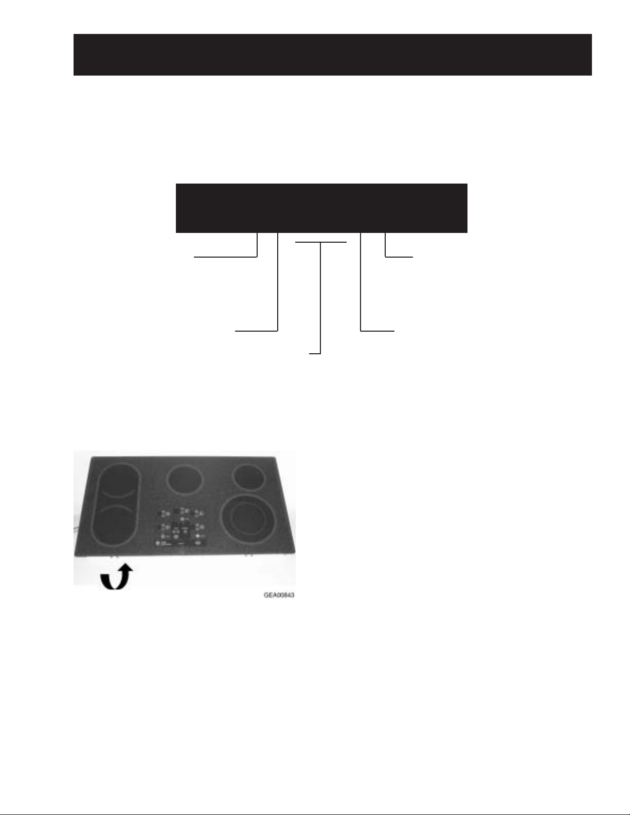
Introduction
The new electronic cooktops make an eloquent
statement of style, convenience, and kitchen
planning flexibility . The electronic touch controls
are simple to understand and easy to operate–just
read and touch.
These cooktops include many helpful features. The
pan detection feature automatically shuts the
heating element OFF after 60 seconds of removing
a metallic pan from the heater . The pan sizing
feature adjusts the heated portion of the dual
element to fit the size of a metallic pan. And the
new warming feature keeps sauces and gravies
warm–or can be used as a normal heating element.
The controls lockout feature protects against
power activation to a heating element during times
of unintended usage or when cleaning the cooktop.
And the convenient kitchen timer can be used with
or without operating the heating elements to
simplify any kitchen task that requires a countdown timer.
It’s easy to see how GE’s fresh ideas can make
anyone more creative in the kitchen!
The information on the following pages will help
you service these new electronic and electric
cooktops effectively and efficiently.
– 2 –
Page 5
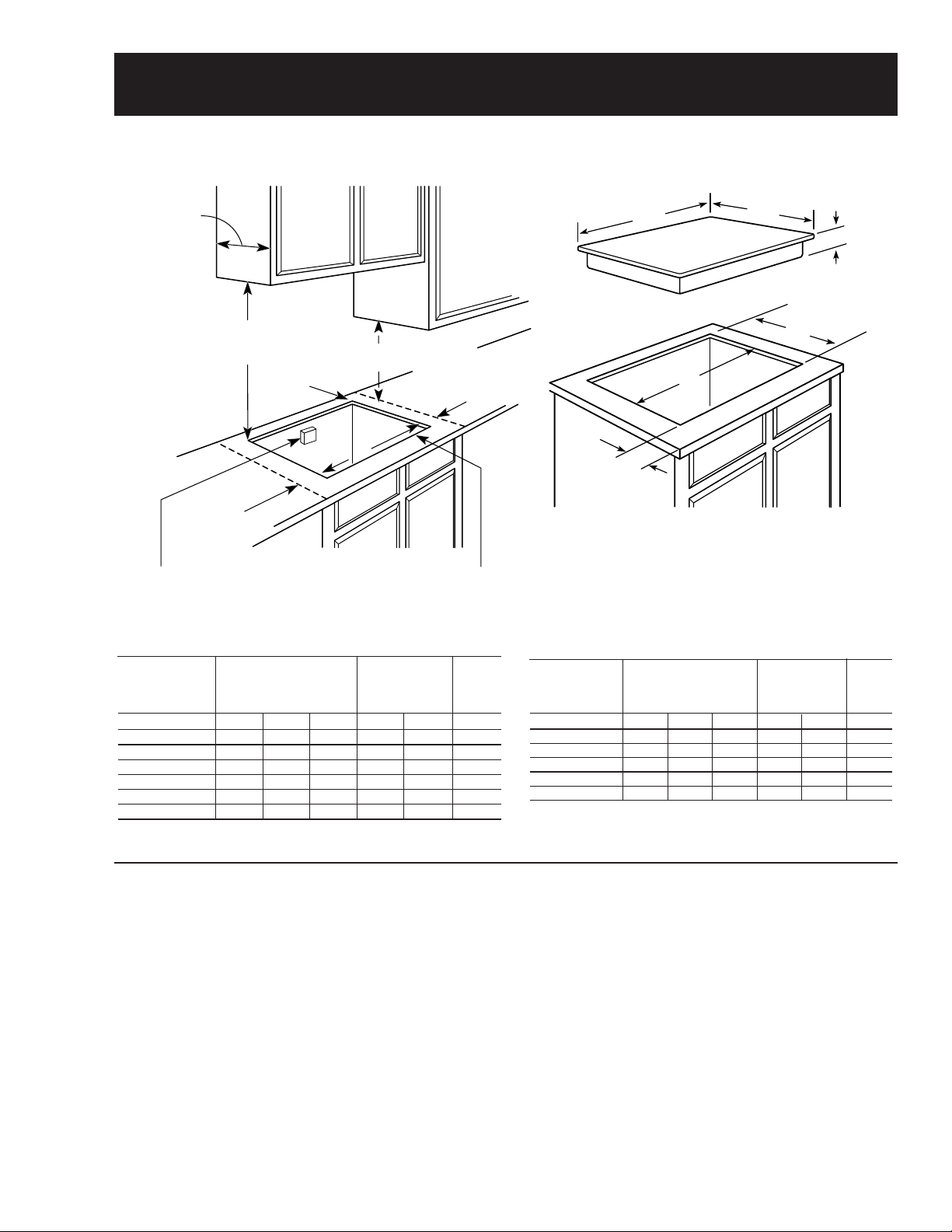
Installation
Electrical junction
box 16" MIN.
below countertop
30" MIN. to
unprotected
cabinet
Cut should not interfere
with cabinet structure
at front
1-3/4" MIN.
clearance to
side wall
from cut-out
1-1/2" MIN.
clearance to
side wall
from cut-out
18" MIN.
to cabinet
1-3/4" to
rear wall
13" MAX.
depth
A
Cooktop
G
E
F
W
D
Counter Installation Dimensions (in inches)
Required
Cooktop Dimensions (in inches)
GEA00791
Dimensions (in inches)
Overall
Model
JP968WC/CC/BC 36 20-3/8 3-1/4* 33-7/8 19-1/8 2-1/2
JP960TC/CC/BC 36 20-3/8 3-1/4* 33-7/8 19-1/8 2-1/2
JP938WC/CC/BC 29-3/4 20-7/8 3-1/4* 28-1/2 19-5/8 2-1/2
JP930TC/CC/BC 29-3/4 20-7/8 3-1/4* 28-1/2 19-5/8 2-1/2
JP350TC/WC/CC/BC
JP340WC/BC 29-3/4 20-7/8 3-1/4* 28-1/2 19-5/8 2-1/2
*Depth of unit at conduit connection location (rear) is 6-1/4" on models JP968/938
and 4-5/8" on models JP960/930/350/340.
WD A E FG
29-3/4 20-7/8 3-1/4* 28-1/2 19-5/8 2-1/2
36-in. and 30-in. Cooktops
Refer to installation instructions. Installation
requires an 18-in. minimum distance from
cooktop to adjacent overhead cabinets. Units are
furnished with a 48-in. flexible armored cable.
Cooktop installation requires a 5-in. free area
between the bottom of the cooktop and any
combustible material, such as shelving. This 5-in.
area is not required when installing a wall oven
underneath the cooktop.
The 36-in. cooktops are approved for use over
GE 30-in. single wall ovens only. The 30-in.
Stainless Steel Cooktop Dimensions (in inches)
To Edge
of Front
Cutout (Min.)
Counter
Model
JP968SC 36-1/8 21 3-1/4* 33-7/8 19-1/8 2-1/2
JP960SC 36-1/8 21 3-1/4* 33-7/8 19-1/8 2-1/2
JP938SC 29-7/8 21-1/2 3-1/4* 28-1/2 19-5/8 2-1/2
GEA00792
JP930SC 29-7/8 21-1/2 3-1/4* 28-1/2 19-5/8 2-1/2
JP350SC 29-7/8 21-1/2 3-1/4* 28-1/2 19-5/8 2-1/2
*Depth of unit at conduit connection location (rear) is 6-1/4" on models JP968/938
and 4-5/8" on models JP960/930/350.
cooktops are approved for use over select GE
27-in. and GE 30-in. single wall ovens.
Note: If installing with a GE Profile Performance™
or GE Profile™ Telescopic Downdraft System,
consult both cooktop and downdraft installation
instructions packed with the products before
installing. Cooktop electric supply may need to be
rerouted to install the downdraft ventilation.
Note: Consult the cabinet and countertop
manufacturer’s specs for flush-mount installation
prior to installing.
– 3 –
Overall
WD A E FG
Cutout (Min.)
To Edge
of Front
Counter
GEA00793
Page 6
Grounding Specifications
Ground Path Resistance 0.10 ohms Max.
Insulation Resistance 250K ohms Min.
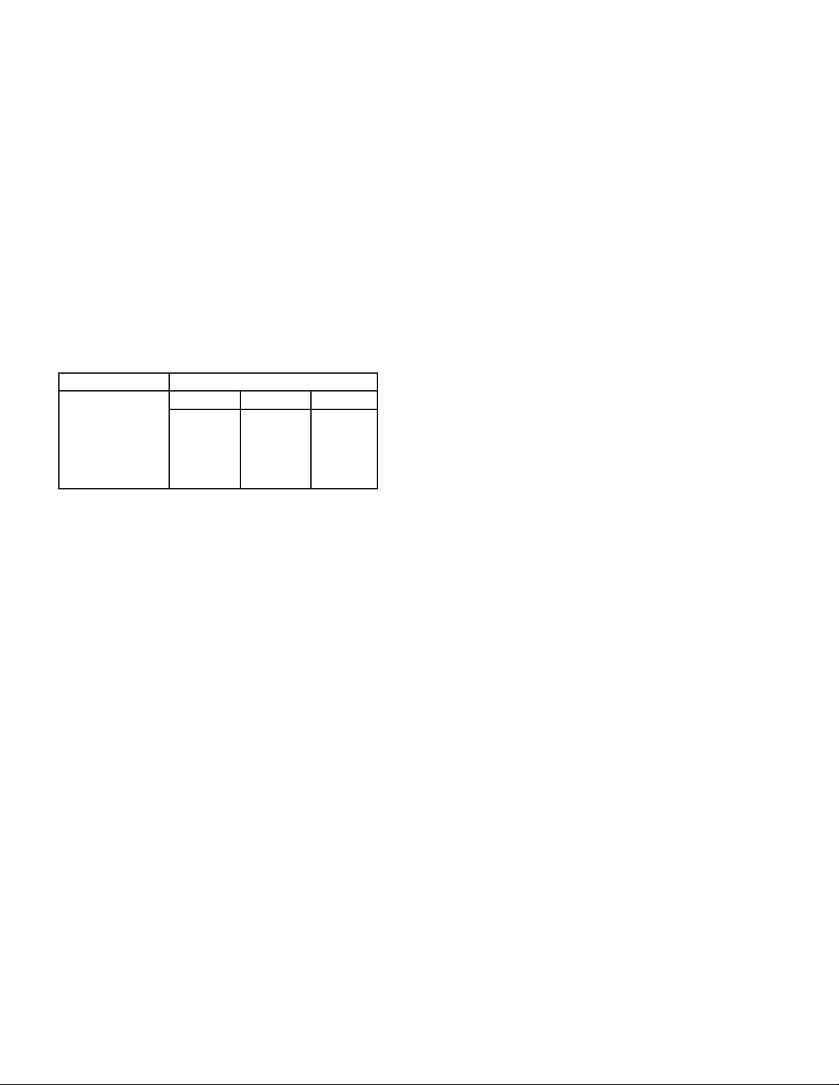
Power Supply Requirements
The cooktop must be connected to a supply
circuit of the proper voltage and frequency as
specified on the rating plate. The rating plate is
located on the side of the component box. Wire
size must conform to the National Electrical
Code or the prevailing local code.
Overcurrent Protection for
Counter-Mounted Cooktops
for a counter-mounted cooktop and not more
than two wall-mounted ovens – all supplied from
a single branch circuit and located in the same
room – shall be computed by adding the nameplate ratings on the individual appliances and
treating this total as equivalent to one range.
Wiring
Built-in power leads are U.L. approved for connection to larger gauge household wiring. The
insulation of these leads is rated at temperatures
much higher than the temperature rating of household wiring. The current carrying capacity of a
conductor is governed by the temperature rating
of the insulation around the wire rather than the
wire gauge alone.
NEC RATING
20 Amp
30 Amp
35 Amp
40 Amp
50 Amp
MAXIMUM KILOWATT RATING
208V 236V 240V
4.2 4.7 4.8
6.2 7.1 7.2
7.3 8.3 8.4
8.3 9.4 9.6
10.4 12.0
11.8
GEA00794
The branch circuit load for one countermounted cooktop is the rating on the nameplate of the appliance. The branch circuit load
WARNING: Improper connection of aluminum
house wiring to these copper leads can result in a
serious problem. Use only connectors designed
for joining copper to aluminum and follow the
manufacturer’s recommended procedure closely.
– 4 –
Page 7
Specifications and Nomenclature
For specifications table, refer to Cooktop Features and Controls, page 11.
Model Number
J P 9 6 8 B C
Product
J = GE Cooking Product
Configuration
P = Cooktop
Feature Pack
Designates features–the higher
the number, the more features.
The serial plate of your cooktop is located
on the bottom of the burner box. In addition
to the model and serial numbers, this plate
tells you the power ratings of the supply
circuit for the cooktop.
Grate Type
C = Continuous
Glass Color
B = Black glass
Serial Number
The first two numbers of the serial number
identify the month and year of manufacture.
Example: AZ123456S = January, 2000
A - JAN 2005 - H
D - FEB 2004 - G
F - MAR 2003 - F
G - APR 2002 - D
H - MAY 2001 - A
L - JUN 2000 - Z
M - JUL 1999 - V
R - AUG 1998 - T
S - SEP 1997 - S
T - OCT 1996 - R
V - NOV 1995 - M
Z - DEC 1994 - L
The letter designating the
year repeats every 12
years.
Example:
T - 1974
T - 1986
T - 1998
Note: The technical sheet is located under the
control panel.
– 5 –
Page 8
Warranty Information
Sales slip or cancelled check is required as proof of original purchase date to obtain
service under warranty.
All warranty service is provided by our Factory Service Centers or an authorized Customer Care® technician.
For The Period Of:
One Year
From the date of the
original purchase
Five Years
From the date of the
original purchase
GE Will Replace:
Any part of the cooktop that fails due to a defect in materials or workman-
ship. During this full one-year warranty, GE will also provide, free of
charge, all labor and in-home service to replace the defective part.
Glass-Ceramic Cooktop, Ribbon Heating Elements and Rubber Seal, if
any of these parts should fail due to a defect in materials or workmanship.
During this limited additional four-year warranty, GE will replace the
defective part free of charge, you will be responsible for service trips and
labor charges.
What GE Will Not Cover:
• Service trips to your home to teach you
how to use the product.
• Improper installation.
• Failure of the product if it is abused, misused, or used for other than the intended
purpose or used commercially.
• Damage to the glass cooktop caused by
use of cleaners other than the recommended cleaning creams.
• Replacement of house fuses or resetting of
circuit breakers.
• Damage to the product caused by accident,
fire, floods, or acts of God.
• Incidental or consequential damage to
personal property caused by possible
defects with this applicance.
• Damage to the glass cooktop caused by
hardened spills of sugary materials or
melted plastic that are not cleaned according to the directions in the Owner’s Manual.
This warranty is extended to the original purchaser and any succeeding owner for products purchased
for home use within the USA. In Alaska, the warranty excludes the cost of shipping or service calls to
your home.
Some states do not allow the exclusion or limitation of incidental or consequential damages. This warranty gives you specific legal rights, and you may also have other rights which vary from state to state.
To know what your legal rights are, consult your local or state consumer affairs office or your state’s
Attorney General.
Warrantor: General Electric Company, Louisville, KY 40225
– 6 –
Page 9
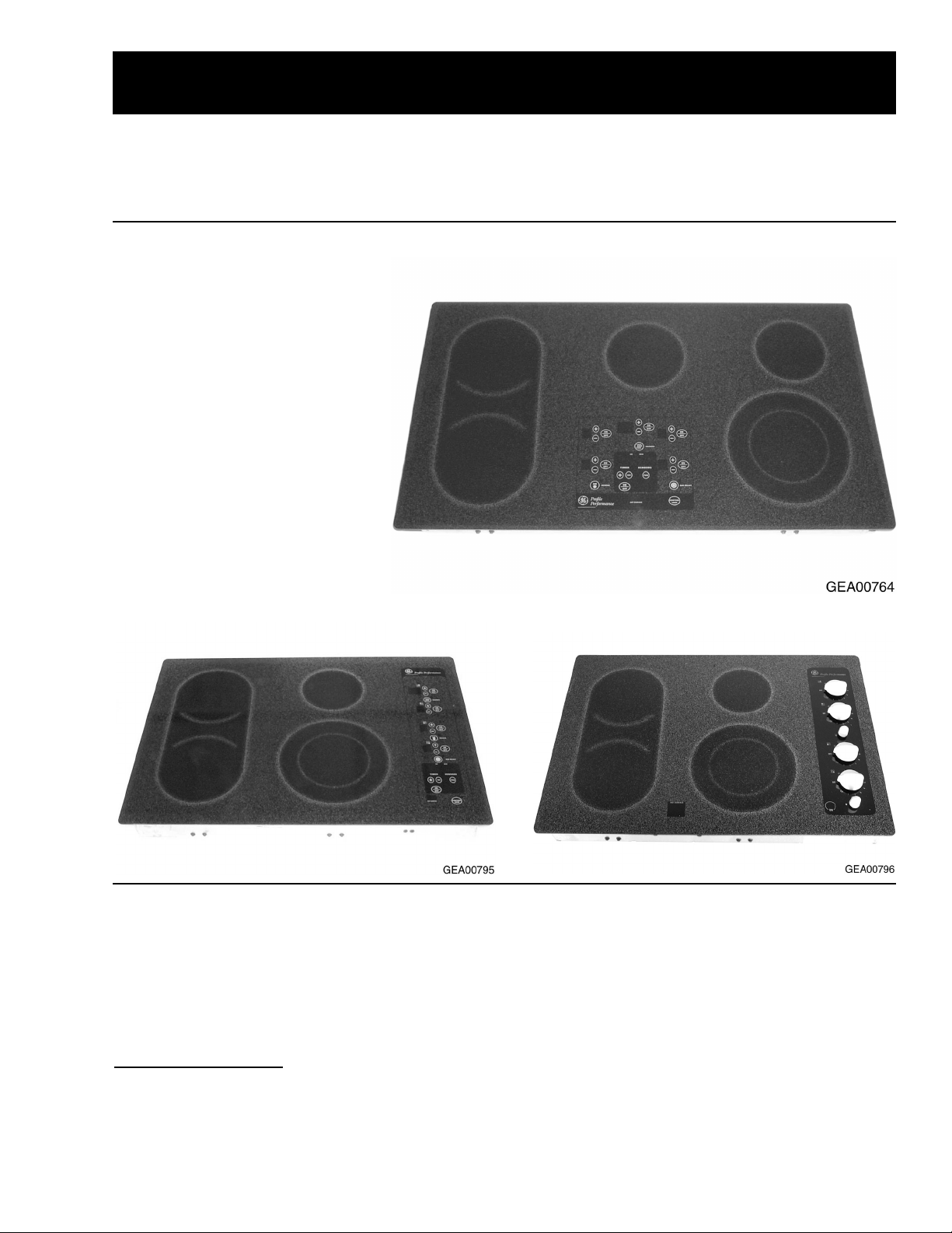
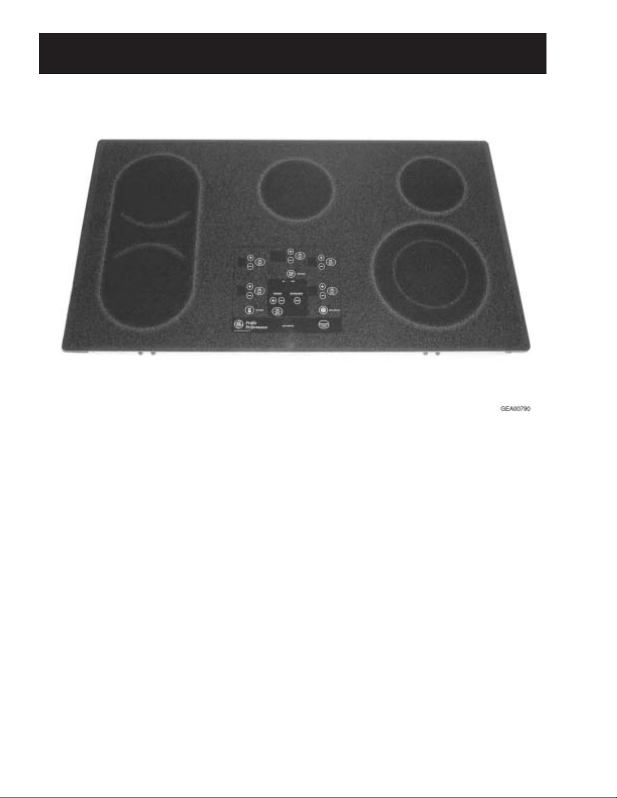
Cooktop Features and Controls
Throughout this manual, features and appearances may vary from the customer’s model.
The new Electronic Touch Control and Electric Manual Control Cooktops encompass over 20 models of
cooktops. They include 30-in., 4-burner and 36-in., 5-burner radiant glass cooktop configurations.
Feature Index
1. Frameless Glass Cooktop
2. Electronic Touch Controls*
3. Pan Detection*
4. Pan Sizing*
5. Control Lock-out*
6. Kitchen Timer*
7. Ribbon-T ype Heating Elements
8. 7-in. Heating/Warming Element*
*Some Models, JP938 & JP968
JP938 (30-in.) Electronic Cooktop
JP968 (36-in.) Electronic Cooktop
JP930 (30-in.) Electric Cooktop
Ceramic Glass Surface
These cooktops feature a ceramic glass cooking
surface over an electric radiant surface element.
The electronic models feature touch controls on
this glass surface that take the place of control
knobs.
Appearance Defects
Scratches, marks from cooking utensils, discoloration, stains, spots, etc. can be caused by food
soils, cookware, cleaning solutions, or water
marks.
Before replacing the cooktop, try using the
cooktop cleaning procedure outlined in the
Owner’s Manual, using the cleaning cream and
Scotch Brite® pad shipped with the product.
Note: When servicing the cooktop, care must be
taken not to scratch or damage the glass.
– 7 –
Page 10
Heating Element Systems
Bridge Element
The Haliant Surface Element consists of a ribbontype resistance wire attached to the support insulation with molded ceramic fiber walls in a corrosionprotected metal dish.
These circular heating elements come in the three
sizes listed below.
Ceramic
Fiber
Molded
Wall
Hot
Light
9" Dual Unit 240 Volt 2500 Watts
9" Ribbon Heating
Element
4
4
Supporting
Insulation
Ceramic Fiber
Molded Wall
6" Ribbon Heating
Element
(6"-1000W., 9"-1500W)
GEA00798
Ribbon Heating
Element
7" 240 Volt-1500 Watts
Hot Light
6" 240 Volt-1200 Watts
Supporting
Insulation
– 8 –
The Bridge Element is made up of two 7-in.,
1800 watt elements plus an 800 watt element
between the two 7-in. elements. The elements
consist of a ribbon-type resistance wire attached
to support insulation with molded ceramic walls.
The digital control on the electronic models (or
the infinite heat switches on the electric models)
regulates the 7-in. units independently of each
other, or in combination when the bridge operating mode (or switch) is selected. The bridge and
the left front element are regulated by the same
controls.
7"-1800 Watt
Elements
Molded
Ceramic
Wall
RTD
RTD
800 Watt
Bridge
Element
GEA00902
Page 11
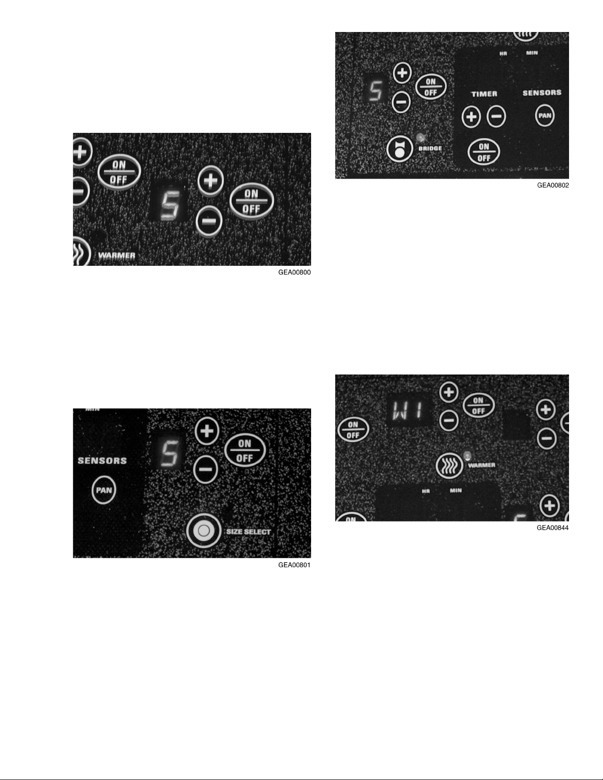
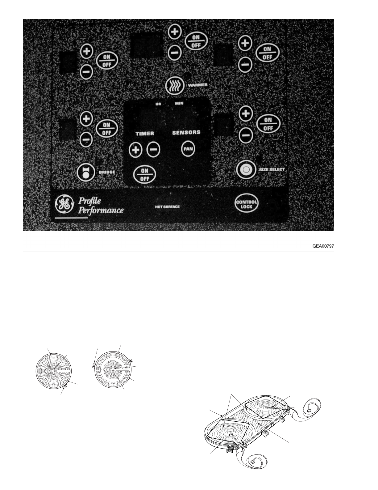
Electronic T ouch Controls (Some Models,
JP938 & JP968)
The touch controls provide precise control of the
surface elements. You can quickly switch from a
steady low heat to full power or any setting in
between.
To turn ON a standard surface element, touch the
ON/OFF pad, then touch the (+) or (-) pad. The
surface element will energize to power setting 5.
Use the (+) or (-) pads to choose the desired
setting: L (low), 1-9, or H (high). The control will
beep each time the pad is touched. To turn the
surface element OFF, touch the ON/OFF pad
again.
To turn ON the bridge element, set the left front
surface element to the desired setting. Touch the
BRIDGE pad. The bridge element will energize to
the same level as the left front surface element
...or, touch the ON/OFF pad for the left front
surface element, then touch the BRIDGE pad.
The left front and bridge elements will both
energize to power setting 5. Using the (+) or (-)
pads will control the setting for both elements. To
turn the bridge element OFF, touch the BRIDGE
pad again. Touching the ON/OFF pad will turn
OFF both the left front and the bridge elements.
To turn ON a 9-in. dual surface element, touch the
ON/OFF pad, then touch the (+) or (-) pad. The
small surface element will energize to power
setting 5. Touch the SIZE SELECT pad to energize
both large and small surface elements. Use the (+)
or (-) pads to choose the desired setting. To turn
the large surface element OFF, touch the SIZE
SELECT pad again. To turn both the large and
small surface elements OFF, touch the ON/OFF
pad.
– 9 –
To turn ON the warmer surface element, touch
the ON/OFF pad, then touch the WARMER pad.
If the surface element is already in use, touch the
WARMER pad. The surface element will energize
to the warmer power setting W1. Use the (+) or
(-) pads to choose the desired warmer setting:
W1, W2, or W3.
To turn OFF the warmer power setting, touch the
WARMER pad again. The surface element will
remain ON in power setting L (low). To turn OFF
the surface element, touch the ON/OFF pad
again.
Page 12
Indicator Lights
Lights will come ON next to the bridge, warmer ,
dual unit, or control lockout pads when touched,
to indicate the surface element or feature is
energized. The light will go OFF when the surface element or feature is turned OFF.
HOT SURF ACE Indicator Lights
The HOT SURFACE indicator lights will glow
when any surface unit is turned ON and will
remain on until the surface has cooled to approximately 150°F.
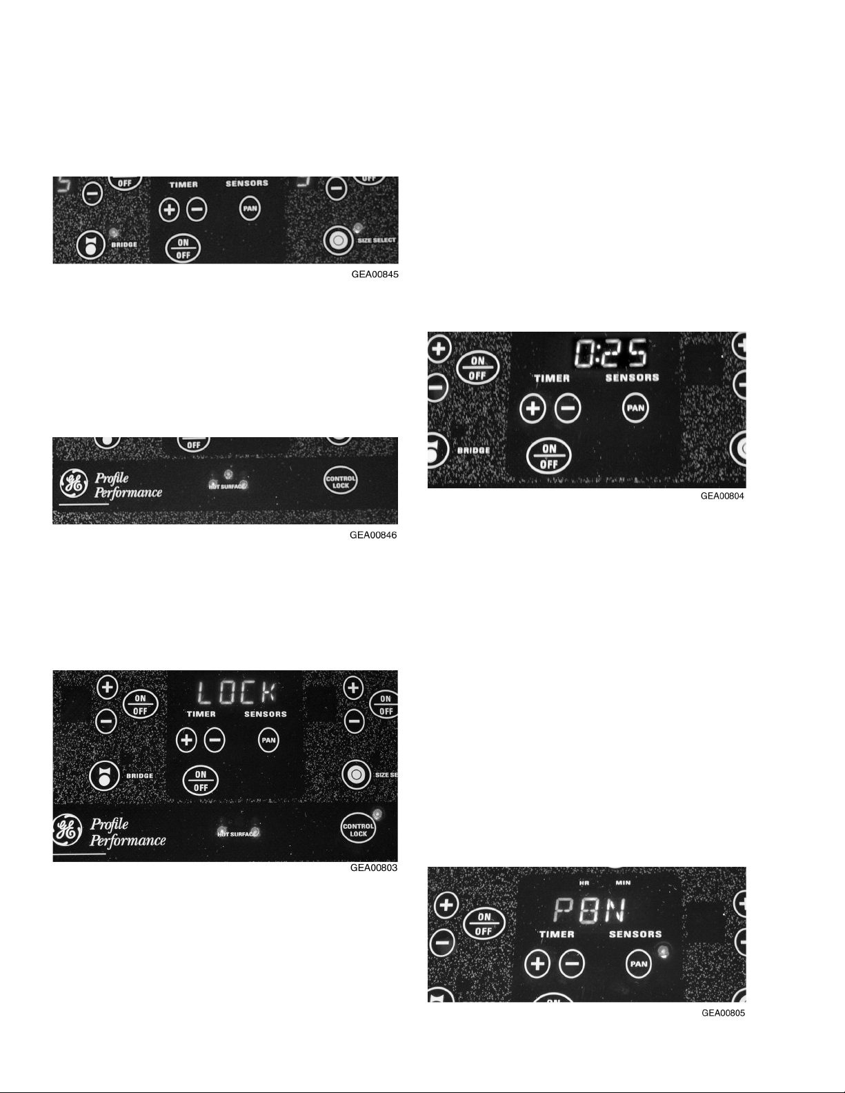
TROL LOCK pad again for 3 seconds. A
2-beep signal will sound and the light will go
out, indicating the cooktop is unlocked.
Locking the cooktop will prevent surface
elements from accidentally being energized by
children or pets. You may lock the cooktop
when not in use or before cleaning.
Kitchen Timer
Operate the timer using the pad below the timer
display . Touch the ON/OFF pad, then touch the
(+) or (-) pad to choose the desired time setting.
If the (+) or (-) pad is held for several seconds,
Controls Lockout
Note: For your convenience, the entire cooktop
can be locked at any time.
To lock the cooktop, touch and hold the CONTROL LOCK pad for 3 seconds. A 2-beep signal
will sound, the word LOCK will appear in the
timer display, and the CONTROL LOCK light will
turn ON indicating the cooktop is locked. If the
cooktop is locked while the surface elements or
timer are in use, they will automatically turn OFF.
the timer will increase or decrease at a faster
rate. After choosing your desired time, the timer
will automatically start to count down from the
hours/minutes you have selected. When the
timer reaches 1 minute, the control will beep
once and the timer will display the remaining
time in seconds until 00:00. The control will then
beep twice every 5 seconds until the timer is
turned OFF.
Pan Detection
Note: For this feature to function properly, the
metallic pan must be at least 4 in. in diameter
and centered on the surface element. This
feature will not work with glass cookware and
must be turned OFF when glass cookware is
used.
To unlock the cooktop, touch and hold the CON-
The pan detection feature works in the following
– 10 –
Page 13

Built-In CleanDesign Cooktops
GE Profile Performance Series
Ribbon
JP968SC JP960SC JP938SC JP930SC JP350TC
JP968WC JP960TC JP938WC JP930TC
JP968CC JP960CC JP938CC JP930CC JP350CC
JP968BC JP960BC JP938BC JP930BC JP350BC JP340BC
Features
Patterned White
Glass-ceramic surface
Number of elements
Dual 6"/9" heating elements
8" heating elements
7" heating element
7" heating elements
Bridge element
Total wattage
6" heating elements
Hot surface indicator lights
Electronic touch controls
Pan presence sensor
Pan size sensor
Patterned Black
5 Ribbon
1 Ribbon w/Warmer
(1500W)
2 Ribbon (1800W)
1 Ribbon (800W)
4400W 4400W 4400W 4400W
1 Ribbon (1200W)
554441
!!
!!
!!
Appearance
SS SS SS SS WW
WW WW WW WW WW
Color appearance*
Frameless
CC CC CC CC CC WW
BB BB BB BB BB BB
Weights & Dimensions
Cooktop width (in inches)
Approx. shipping weight (lbs.)
36 36 30 30 30 30
45 44 38 38 38 35
Power/Ratings
KW rating @ 240V
208V 7.2 7.2 6.1 6.1 5.8 4.8
Amps @ 240V
208V 40 40 40 30 30 30
*SS = Stainless Steel, WW = White on white, CC = Bisque, BB = Black on black.
9.6 9.6 8.1 8.1 7.7 6.4
40 40 40 40 40 30
Patterned BlackPatterned Black
TrueWhite
Patterned BisquePatterned Bisque
Patterned Black
5 Ribbon
1 Ribbon (2500W)1 Ribbon (2500W)
1 Ribbon (1500W)
2 Ribbon (1800W)
1 Ribbon (800W)
1 Ribbon (1200W)
™
Patterned Black
True White
Patterned Bisque
Patterned Black
4 Ribbon
1 Ribbon (2500W)
2 Ribbon (1800W)
1 Ribbon (800W)
1 Ribbon w/Warmer
(1200W)
Patterned Black
True White
Patterned Bisque
Patterned Black
4 Ribbon
2 Ribbon (2500W)
2 Ribbon (1800W)
1 Ribbon (800W)
1 Ribbon (1200W)
GE Profile
™
Ribbon
JP350SC
JP350WC
Patterned Black
True White
Patterned White
Patterned Bisque
Patterned Black
4 Ribbon
2Ribbon (2500W)
2 Ribbon (2000W)
2 Ribbon (1200W)
SS
GE
Ribbon
JP340WC
Patterned White
Patterned Black
4 Ribbon
2 Ribbon (2000W)
2 Ribbon (1200W)
GEA00806
manner: after energizing one of the heating
elements, a pan must be placed on the surface
element within 60 seconds. If a pan is not placed
on the surface element within 60 seconds, the
surface element will turn OFF. If a pan is removed from the surface element, the user has
60 seconds to replace it before the surface
element is automatically turned OFF. The power
level display will flash when the control on the
surface element detects the absence of a pan.
To activate or deactivate the pan detection
feature for all surface elements, touch the PAN
pad. A signal will sound and a light next to the
P AN p ad will indicate whether the feature is
active. If the light is ON, then the pan detection
feature is ON. When the pan detection feature is
OFF, the pan sizing feature is also OFF.
Pan Size Sensor
Note: This feature is only for the dual unit
surface elements and functions only when the
pan detection feature is turned ON.
When a small pan is placed on the surface
element, the small surface element will activate.
When a large pan is placed on the surface
element, the small and large surface elements
will activate. This feature may be overridden for
a single cooking session while leaving the pan
detection feature ON.
To activate or deactivate this feature and the
pan detection feature, touch the P AN pad. The
light next to the P AN pad will go out, indicating
that both pan detection features are turned
OFF.
– 11 –
Page 14

Diagnostics
Table of Contents
Digital Control System . . . . . . . . . . . . . . . . . . . . . . . . . . . . . . . . . . . . . . . . . . . . . 13
Triac Voltage Control . . . . . . . . . . . . . . . . . . . . . . . . . . . . . . . . . . . . . . . . . . . . . . 13
Pan Detection . . . . . . . . . . . . . . . . . . . . . . . . . . . . . . . . . . . . . . . . . . . . . . . . . . . . 14
Technician Mode . . . . . . . . . . . . . . . . . . . . . . . . . . . . . . . . . . . . . . . . . . . . . . . . . . 14
Fault Codes (F-codes) . . . . . . . . . . . . . . . . . . . . . . . . . . . . . . . . . . . . . . . . . . . . . 15
Line-In Voltage Check . . . . . . . . . . . . . . . . . . . . . . . . . . . . . . . . . . . . . . . . . . . . . . 15
Temperature Check (in Celsius) . . . . . . . . . . . . . . . . . . . . . . . . . . . . . . . . . . . . . 15
Frequency Check (in Hertz) . . . . . . . . . . . . . . . . . . . . . . . . . . . . . . . . . . . . . . . . . 16
Calibration of the Inductive Pan Sensors . . . . . . . . . . . . . . . . . . . . . . . . . . . . . . 16
Fault Code Behavior Table . . . . . . . . . . . . . . . . . . . . . . . . . . . . . . . . . . . . . . . . . . 17
– 12 –
Page 15

Digital Control System
The control system consists of four circuit boards:
the touch board (which is permanently adhered to
the ceramic glass panel) that senses the user
input, the display board that contains the panel
displays, the logic board that contains the microprocessor , and the power board that does the
power switching and control of the heating units.
Ceramic
Glass With
Touch Board
Display
Board
Logic
Board
Power Board
Permanently
Adhered
Burner
Box
Drop Box
Cover
GEA00807
• If the touch board is damaged, the entire glass
assembly must be replaced.
• If the display board is damaged, it can be
replaced by removing the glass top and disconnecting the display board from the touch board.
• If the logic board is damaged, it can be replaced
by removing the glass top and removing the logic
board from the area under the keypad.
• If the power board is damaged, it can be accessed by removing the drop box cover that is
under the cooktop.
Note: No individual components on the boards
are replaceable.
Triac Voltage Control
A triac-fired control replaces the usual rheostat
temperature control for each surface element. The
control receives feedback from the temperature
sensor to allow for precise control of the heating
element power.
– 13 –
Page 16

Pan Detection
Temperature Sensor
Sensor Connectors
Technician Mode
The pan detection system includes a pan sensor,
an inductive sensor interface chip (ISIC) permanently mounted on the logic board, and a signal
wiring harness connecting the sensor with the
ISIC.
Temperature Sensor
Temperature Sensor Sensor Connectors
Sensor Connectors
Logic BoardLogic BoardHeaterHeaterPan SensorPan Sensor
GEA00766
The pan sensor determines the presence or
absence of a pan through a change in the magnetic field. When a metal pan is near the sensor ,
the resonant frequency of the pan increases. This
information is passed to the ISIC, which determines a pan to be present. When the frequency
drops to a specified level, the ISIC determines the
pan to not be present and turns the surface
element OFF after 1 minute.
To enter the Technician Mode, lock the cooktop by
holding the CONTROL LOCK key for 3 seconds.
The control will beep 2 times and the word LOCK
will be displayed in the timer display . Press the
timer ON/OFF key and simultaneously press the +
keys of the LF and LR surface elements. The timer
display will flash TECH MODE when the cooktop
is in Technician Mode.
Pan Size Feature
When the pan detection feature is active, the pan
size feature is also active. The pan size feature is
designed to automatically recognize the size of a
pan placed on the dual heater and energize one or
both cooking zones to match the size of the pan.
The pan size feature is overriden when the DUAL
key is pressed.
To exit the Technician Mode, simultaneously press
the timer ON/OFF key and the (+) keys of the LF
and LR surface elements, or unlock the cooktop
by holding down the CONTROL LOCK key for 3
seconds. The control will beep 2 times and the
CONTROL LOCK LED will turn OFF.
– 14 –
Page 17

Fault Codes (F-codes)
When a fault code (F-code) occurs, an alarm will
sound for 1 minute, the F-code will flash in the
timer display, and F will flash in the display in the
window of the failed surface element until acknowledged by touching the CONTROL LOCK key. The
displays are then cleared. If the fault still exists, or
if it recurrs when the user tries to activate a surface element, the F-code will redisplay .
To clear the F-code register , enter Technician
Mode. While the timer display flashes TECH
MODE, simultaneously press the BRIDGE and
WARMER keys. The timer display will display
DONE and the F-codes will be permanently
deleted from the register .
Note: A complete fault codes table can be found
at the end of this section.
Line-In Voltage Check
To check the line-in voltage, press the timer ON/
OFF key while in Technician Mode. Line-in voltage
will appear in the timer display .
Only the severest F-codes are immediately displayed. Less severe F-codes are recorded, then
displayed based on the number of repeated occurrences.
The Technician Mode allows the last 9 F-codes to
be recalled from the register and displayed on the
timer display . The most recent F-code is displayed
first (as #1). Pressing the TIMER (+) and TIMER
(-) keys will scroll up and down the last 9 recorded
F-codes.
The cooktop has multiple sensors, one for each
surface element. Some F-codes include a sensor
number associated with a surface element. The
illustration below shows the sensor/surface element number for both cooktop configurations.
2
1
34
5
2
1
4
5
Temperature Check (in Celsius)
To check the temperature of a specific surface
element, press that element’s ON/OFF key while
in T echnician Mode. C will display in the window of
the specific surface element and the temperature
will appear in the timer display .
– 15 –
Page 18

Frequency Check (in Hertz)
To check the frequency of a specific pan sensor,
press the (-) key of that element while in Technician Mode. H will display in the window of the
specific surface element. The frequency will
appear in the timer display .
Calibration of the Inductive Pan Sensors
Calibration of the inductive sensors is performed
to permanently store the pan detection thresholds
in a new logic board that has never been calibrated. Calibration is also performed to update the
pan detection thresholds due to a physical change
in the pan detection circuit, wiring, or sensor .
Calibration of the inductive sensors is necessary
and must be performed when any of the radiant
surface elements (with an inductive sensor) are
replaced or when the logic board is replaced.
Note: The procedure for calibration of the inductive sensors can be found in the Mechanical
Disassembly section.
– 16 –
Page 19

Fault Code Behavior Table
– 17 –
Page 20

Mechanical Disassembly
Table of Contents
Nonelectronic Models . . . . . . . . . . . . . . . . . . . . . . . . . . . . . . . . . . . . . . . . . . . . . . 19
Glass and Cooktop Removal from Countertop . . . . . . . . . . . . . . . . . . . . . . . 19
Broken Glass Replacement. . . . . . . . . . . . . . . . . . . . . . . . . . . . . . . . . . . . . . . 19
ON Light Replacement . . . . . . . . . . . . . . . . . . . . . . . . . . . . . . . . . . . . . . . . . . . 19
Switch Replacement . . . . . . . . . . . . . . . . . . . . . . . . . . . . . . . . . . . . . . . . . . . . 19
HOT SURFACE Light Replacement . . . . . . . . . . . . . . . . . . . . . . . . . . . . . . . . 20
Burner Replacement . . . . . . . . . . . . . . . . . . . . . . . . . . . . . . . . . . . . . . . . . . . . 20
Electronic Models . . . . . . . . . . . . . . . . . . . . . . . . . . . . . . . . . . . . . . . . . . . . . . . . . 21
Glass and Cooktop Removal from Countertop . . . . . . . . . . . . . . . . . . . . . . . 21
Touch Board and Cooktop Glass Replacement . . . . . . . . . . . . . . . . . . . . . . 22
Display Board Replacement . . . . . . . . . . . . . . . . . . . . . . . . . . . . . . . . . . . . . . 22
Logic Board Replacement . . . . . . . . . . . . . . . . . . . . . . . . . . . . . . . . . . . . . . . . 22
Power Board Replacement . . . . . . . . . . . . . . . . . . . . . . . . . . . . . . . . . . . . . . . 23
Calibration Instructions for the Inductive Sensors. . . . . . . . . . . . . . . . . . . . 24
Surface Element Replacement . . . . . . . . . . . . . . . . . . . . . . . . . . . . . . . . . . . . 25
– 18 –
Page 21

NONELECTRONIC MODELS
WARNING: Before servicing the cooktop,
power must be removed from the cooktop by
pulling the plug out of the outlet or turning the
power off at the circuit breaker.
Remove these screws
Glass and Cooktop Removal from
Countertop
1. Remove all cooktop hold-down retainers from
below the edge of the countertop.
2. Protect the counter with two strips of wood or
cardboard as shown below.
3. Reach up from inside the cabinet and push
upward on the bottom of the burner box enough
to shim with protective wood or cardboard
under one end. Repeat for the other end.
Caution: Screws on the bottom of the burner box
can scratch the countertop surface. Use care to
protect the countertop appearance.
6. Remove all screws from along the top edge on
all 4 sides of the burner box. Remove the
cooktop glass and place it top side down on a
protected surface.
Broken Glass Replacement
1. Remove the glass and cooktop from the
countertop (see the previous procedure).
2. Remove the rubber grommets from the broken
glass.
3. With a drop of liquid soap on your fingertip, wet
the rims of all holes in the new glass and gently
twist (do not force) the grommets through the
holes.
ON Light Replacement
1. Remove the glass and cooktop from the
countertop (see procedure).
GEA00847
4. Using the shims to get a handhold under the left
and right sides of the glass, carefully raise the
cooktop up about 4 in., rotate slightly left or
right (to the best working advantage), and set
down as shown. Lift each end slightly and
adjust the wood or cardboard to prevent
scratching the countertop.
5. Remove all knobs from the cooktop.
2. Compress the ON light wings, as shown, and
pull down to remove from the bracket.
3. Remove the wires from the ON light.
Switch Replacement
1. Remove the glass and cooktop from the
countertop (see procedure).
– 19 –
Page 22

2. Remove 4 screws from the switch mounting
bracket (2 from each end).
3. Remove 2 screws and the switch from the
mounting bracket.
4. Tag and remove the wires from the switch.
HOT SURFACE Light Replacement
1. Remove the glass and cooktop from the
countertop (see procedure).
2. Remove 2 screws from the burner box and
remove the HOT SURFACE light mounting
bracket.
LR Burner SwitchLR Burner Switch
GEA00814
4. Remove 4 screws from the switch mounting
bracket (2 from each end) and remove the red
wire from the switch for the left rear burner .
5. Note the location and color of the wires in the
wire harness, disconnect them from the burners, and remove.
Note: When installing the new HOT SURF ACE
light, be sure to feed the harness under the brace
below the right-hand burners.
Burner Replacement
1. Remove the glass and cooktop from the
countertop (see procedure).
3. With a small screwdriver , push in on the first
light tab while pushing down on the light. Push
in on the second light tab, while still pushing the
light down, to release the light.
2. Note the position of the wires to the burner.
Remove the wires.
– 20 –
Page 23

Mark Numbers
Mark Numbers
Mark Numbers
Next to Tabs
Next to Tabs
ELECTRONIC MODELS
WARNING: Before servicing the cooktop,
power must be removed from the cooktop by
pulling the plug out of the outlet or turning the
power off at the circuit breaker .
Glass and Cooktop Removal from
Countertop
Note: The ceramic glass and touch board shall be
supplied as a complete assembly.
1. Remove all cooktop hold-down retainers from
below the edge of the countertop.
2. Protect the counter with two strips of wood or
cardboard as shown below.
3. Reach up from inside the cabinet and push
upward on the bottom of the burner box enough
to shim with protective wood or cardboard
under one end. Repeat for the other end.
Caution: Screws on the bottom of the burner box
can scratch the countertop surface. Use care to
protect the countertop appearance.
GEA00817
3. Lift the burner off the springs and mark the
numbers on the bottom of the burner next to the
tabs.
4. Remove the tabs and install them on the new
burner in the same numbered position.
Note: When installing the new burner , make sure
the 2 springs are on the 2 posts.
GEA00847
4. Using the shims to get a handhold under the left
and right sides of the glass, carefully raise the
cooktop up about 4 in., rotate slightly left or
right (to the best working advantage), and set
down as shown. Lift each end slightly and
adjust the wood or cardboard to prevent
scratching the countertop.
Remove these screws
5. Remove all screws from along the top edge on
all 4 sides of the burner box and slowly lift the
front of the glass off the burner box.
– 21 –
Page 24

6. With the glass tilted at an angle, disconnect the
wire harness that extends from the logic board
to the user interface by pulling upward on the
connector. Do not pull on the wires.
7. Remove the glass from the top of the burner
box and place top side down on a protected
surface.
3. Prop the glass on the back of the cooktop.
Using one hand to lower the glass, use the
other hand to connect the wire harness from the
display board to the 10-pin header on the logic
board.
4. Lower the glass onto the burner box, being sure
not to pinch any wires between the frame and
the burner box.
Touch Board and Cooktop Glass
Replacement
Note: The ceramic glass and touch board shall be
supplied as a complete assembly . Remove and
replace the cooktop ceramic glass (see previous
procedure).
Display Board Replacement
1. Remove the display board from the damaged
piece of cooktop glass.
5. Apply power to the cooktop. Once the cooktop
appears to be in working order, remove power
from the cooktop and insert all the screws to
secure the glass to the burner box.
Logic Board Replacement
1. Remove the glass and cooktop from the
countertop (see procedure).
SensorSensor
GEA00822
2. Place the display board on the new cooktop
glass, making sure to connect the 8-pin ribbon
cable to the touch board and the wire harness
to the display board.
2. Disconnect the sensor connectors from the
logic board by pulling upward on the connectors. Do not disconnect the connectors by
pulling on the sensor wires.
– 22 –
Page 25

Press Down on Latching TabsPress Down on Latching Tabs
26-Pin
26-Pin
Ribbon Cable
Ribbon Cable
GEA00823
3. Disconnect the 26-pin ribbon cable from the
logic board by pressing down on the latching
tabs of the header .
10-Pin
10-Pin
Header
Header
GEA00848
8. Prop the glass onto the back of the cooktop.
Using one hand to lower the glass, use the
other hand to connect the wire harness from the
user interface to the 10-pin header on the logic
board.
TabsTabs
GEA00824
4. Remove the logic board by using needle nose
pliers to press in on the tabs of the logic board
standoffs, and lifting the board. Do not remove
the logic board standoffs. Repeat this procedure for all 5 board standoffs.
Caution: To avoid delivering an electric shock to
the new logic board, place your hand on the
burner box for at least 2 seconds before reaching
for the new logic board.
5. Remove the new logic board from the antistatic
bag and place it on top of the standoffs.
Note: 30-in. cooktops do not have a connector
placed on J503 (for the CR heater of a 36" unit),
and the connectors are keyed to prevent a
misconnection.
9. Lower the glass onto the burner box, being sure
not to pinch any wires between the frame and
the burner box.
10. Apply power to the cooktop. An F161 is ac-
ceptable if a surface element is turned on with
the pan detection feature active. This indicates
the need to calibrate the inductive sensors.
11. Once the cooktop appears to be in working
order , remove power from the cooktop and
insert all the screws to secure the glass to the
burner box.
Note: After the cooktop has been placed back into
the consumer’s counter and power has been
applied, the cooktop must be calibrated. Proceed
to the Calibration Instructions for the Inductive
Sensors.
Power Board Replacement
1. Remove the glass and cooktop from the
countertop (see procedure).
2. Turn the cooktop 180 degrees and prop the
cooktop up to access the drop box. Be careful
not to damage the counter.
6. Reconnect the 26-pin wire harness and the
sensor connectors to their original positions.
7. Examine the inside of the cooktop (heaters,
sensors, wires, and thermal wall) for anything
that does not look normal.
– 23 –
Page 26

3. Remove 5 screws and the ground screw from
26-Pin Cable
Main Power Connector
Power
Connector
the drop box cover and lower the cover.
Main Power Connector
Main Power Connector
26-Pin Cable
26-Pin Cable
GEA00826
4. Disconnect the main power connector in the
drop box.
5. Disconnect the 26-pin ribbon cable from the
power board by pressing down on the latching
tabs of the header .
Power
Power
Connector
Connector
9. Prop the glass onto the back of the cooktop.
Using one hand to lower the glass, use the
other hand to connect the wire harness from
the user interface to the 10-pin header on the
logic board.
10. Lower the glass onto the burner box, being
sure not to pinch any wires between the frame
and the burner box.
11. Apply power to the cooktop. Once the cooktop
appears to be in working order , remove power
from the cooktop and insert all the screws to
secure the frame to the burner box.
6. Disconnect the power connector in the burner
box.
Caution: To avoid delivering an electric shock to
the new power board, place your hand on the
burner box for at least 2 seconds before reaching
for the new power board.
7. Remove the new power board from the anti-
static bag and reconnect the 26-pin wire harness, the main power connector , and the burner
box power connector to their original positions.
8. Examine the inside of the cooktop (heaters,
sensors, wires, and thermal wall) for anything
that does not look normal.
Calibration Instructions
for the Inductive Sensors
Note: Calibration of the inductive sensors must
begin with the LF surface element and proceed in
a clockwise direction around the cooktop. All of
the sensors must be calibrated to complete the
calibration procedure.
• Calibration of the inductive sensors must begin
within 15 minutes of applying power to the
cooktop.
1. Clear everything from the top of the glass.
2. Lock the control by pressing the control LOCK
key for 3 seconds. The control LOCK LED will
turn ON.
3. Enter tech mode by pressing the TIMER
ON/OFF, LF (+), and LR (+) keys at the same
time. The TIMER window will flash the words
TECH MODE.
4. Begin the calibration procedure by pressing the
TIMER ON/OFF, LF (+), and RF (+) keys at
the same time. The TIMER window will flash
CAL and the LF surface element power window will flash the U symbol.
– 24 –
Page 27

5. When the TIMER window displays DISC and
the U symbol stops flashing in the LF surface
element power window, center the aluminum
disk on the LF surface element.
6. Press the PAN and LF (+) keys at the same
time. The electronic control will perform the
calibration on the LF sensor and then proceed
to the next surface element. The TIMER
window will flash CAL and the U symbol will
flash in the LR surface element power window.
7. Repeat steps 5 and 6 for the LR, CR (if
present), RR, and RF surface elements.
8. After the RF surface element has been calibrated, the timer window will display a PASS or
F AIL message for the entire calibration procedure. An F will be displayed in the surface
element power window of any sensor that fails
the process. Acknowledge this message and
exit the calibration procedure by pressing the
PAN and RF (+) keys at the same time.
Note: If the calibration proceedure is interupted for
any reason, exit the calibration proceedure by
pressing the PAN and RF (+) keys at the same
time.
Note: Failure of the calibration procedure may
occur for several reasons. If the calibration procedure fails, follow these steps:
• T ry calibrating the cooktop again, beginning with
step 1 from above.
2. Disconnect the appropriate sensor connector
from the logic board by pulling upward on the
connector. (Do not disconnect the connector by
pulling on the sensor wires.) T race the sensor
wires back to the appropriate surface element,
making note of where and how the wires are
routed.
Caution: Do not cut the wire ties from the wire
harness. Care must be taken to ensure that
only the sensor wires to the surface element
being replaced are cut.
Caution: Routing of the wires is extremely
critical. Care must be taken to ensure the wires
are routed exactly the way they were originally.
Remove Cut Wires
From Wire Bundle
Sensor Wire
Harness
• Identify the sensor(s) that fails the calibration
procedure.
• If multiple sensors fail the calibration procedure,
replace the logic board.
• If only one sensor fails the calibration procedure,
replace the corresponding surface element.
Surface Element Replacement
Note: The surface element, pan sensor, and
temperature sensor are only replaceable as an
assembly, which includes the sensor wire harness
and connector.
1. Remove the glass and cooktop from the
countertop (see the procedure).
– 25 –
Old Heating
Element
Tie Wrap (Do Not Cut)
To Power Board
Surface Element
Power Wires
GEA00756
3. Using diagonal cutters, snip both the tempera-
ture sensor and the pan sensor wires and
remove them from the wire harness leading
from the logic board to the surface element.
Note: When installing the new surface element,
tie-wrap temperature sensor and pan sensor wires
to the existing wire harness. Do not cut existing
wire harness. Do not cut existing tie wraps.
Existing Wire Ties
(Do Not Cut)
Tie-Wrap New Wires
To Wire Bundle
New Heating
Element
To Power Board
Surface Element
Power Wires
GEA00861
Page 28

4. Remove the electrical connectors form the
heater.
5. Lift the heater off the springs and mark the
numbers on the bottom of the heater next to the
tabs.
6. Remove the tabs and install them on the new
surface element in the same numbered position.
Note: When installing the new surface element,
make sure a spring is beneath every mounting
bracket.
7. Place the new surface element on the mounting
posts.
8. Position the sensor harness in the same manner
as the original harness was oriented, being sure
to keep all wires away from all surface elements.
9. Using a nut driver, remove the necessary
screws from the outside of the burner box and
lift the surface element support bracket to
route the sensor wires beneath the bracket.
10. Run the connector through the gap between
the insulating strip and the thermal wall,
making a slit in the insulating strip if necessary.
11. Place the connector on the appropriate header
on the logic board.
12. Beginning at the end of the wire harness
closest to the surface element, secure the
sensor wires to the existing wire harness with
wire ties. Trim the excess material from the
wire ties and make sure the new wire harness
is in the same position as the original.
– 26 –
Page 29

Heater
Component and Connector Locator Views
JP968 (36-in.) Electronic Cooktop
26-Pin Ribbon
26-Pin Ribbon
Connector
Connector
Main Power
Main Power
Connector
Connector
Power BoardPower Board
Ceramic Glass TopCeramic Glass Top
Display BoardDisplay Board
Touch BoardTouch Board
Ceramic
Ceramic
Glass Top
Glass Top
Sensor
Sensor
Connector
Connector
26-Pin Ribbon
26-Pin Ribbon
Connector
Connector
Display Board/Touch
Display Board/Touch
Board Assembly
Board Assembly
User Interface to Logic
User Interface to Logic
Board Wire Harness
Board Wire Harness
Temperature
Temperature
Sensor (RTD)
Sensor (RTD)
10-Pin Header10-Pin Header
– 27 –
Pan SensorPan Sensor
Support BracketSupport Bracket Heater
HeaterBurner BoxBurner BoxLogic BoardLogic Board
GEA00834
Page 30

JP938 (30-in.) Electronic Cooktop
26-Pin Ribbon
26-Pin Ribbon
Connector
Connector
Main Power
Main Power
Connector
Connector
Power
Power
Board
Board
Ceramic
Ceramic
Glass Top
Glass Top
User Interface to Logic
User Interface to Logic
Board Wire Harness
Board Wire Harness
Pan
Pan
Sensor
Sensor
Burner
Burner
Box
Box
Display
Display
Board
Board
Temperature Sensor (RTD)Temperature Sensor (RTD)HeaterHeater
Power ConnectorPower Connector
Touch
Touch
Board
Board
26-Pin Ribbon
26-Pin Ribbon
Connector
Connector
Sensor
Sensor
Connectors
Connectors
10-Pin
10-Pin
Header
Header
– 28 –
Logic BoardLogic BoardSupport BracketSupport Bracket
GEA00835
Page 31

JP350 (30-in.) Electric Cooktop
HOT SURFACE
Burner BoxBurner Box HOT SURFACE
HOT SURFACE
Lights
Lights
HeaterHeater
Support
Support
Bracket
Bracket
Thermal LimiterThermal Limiter
ON LightON Light
SwitchSwitch
Switch
Switch
Mounting
Mounting
Bracket
Bracket
GEA00838
– 29 –
Page 32

– 30 –
INDUCTIVE
SENSOR
LF
BRIDGE
LB
LR
WIRE
1800W
R
T
D
1
2
J501 CONNECTOR
800W
2
1
1800W
R
T
D
1
Yellow
with
traces
(jumper
wire)
9-PIN POWER
CONNECTOR
3
12
6
4
5
9
7
CONDUIT
WIRING CHART
COLOR NUMBER (PIN #) (PIN #) TERMINAL #
YELLOW J101 1 LF1
YELLOW J102 11 LF2
ORANGE J103 13 LR2
ORANGE J104 4 LR1
GRAY J105 5 CR1
BROWN J106 12 RR2
BROWN J107 2 RR1
VIOLET J108 3 RF21
BLUE/BLK J109 15 RF22
BLUE J110 6 RF12
GRAY J111 14 CR2
YEL/BLK J112 10 LB2
GEA00903
BOARD REFERENCE CONNECTOR HEATER CONNECTOR BURNER
8
J122
J107
J115 / J116
J109
K107
J110
K106
POWER 9-PIN POWER 15-PIN CONTROL/
J113 L1 1
J114 L1 3
J115 L1 2
J116 L1 2
J117 L1 4
J118 L2 7
J119 L2 6
J120 L2 9
J121 L2 9
J122 a 8
K105
J120/J121
2
J106
J108
J117
K
1
0
4
J502
J102
J120 / J121
RELAYS
JP968 MODEL ONLY
CR
1500W
R
T
D
1
2
J104
J114
J111
J118
J113
J101
K102 K101
POWER BOARD
J112
J503
J105
K
1
0
3
RR
1200W
R
T
D
1
2
1
2
J505
15-PIN CONTROL
HEATER CONNECTOR
J115 / J116
J103
J119
J100
J504
1
3
2
6
4
5
9
7
8
12
11
10
15
13
14
J503
J501
J502
J504
J505
J602
MAIN BOARD
26 PIN
RIBBON
Caution: Label all wires prior to disconnection when
servicing the controls. Wiring errors can cause
improper and dangerous operation. Verify proper
operation after servicing.
RF2
1500W
1000W
R
T
D
Example:
Empty Pin
10 Pin Ribbon
8 PIN
RIBBON
RF1
Blue
RTD Wire
(Pin 5)
2
1
4
E
DISPLAY
BOARD
TOUCH
BOARD
Blue
with
Black
Traces
Inductive
Sensor
123
(Pin 1)
Schematics
Page 33

Notes
– 31 –
Page 34

Parts List
– 32 –
Page 35

Ref No. Part No. Description Qty.
16 WB27T10293 Logic Board 1
18 WB27T10294 Display Board 1
44 WB02T10092 Burner Box Grommet 1
51 WB62T10088 Glass Maintop Asm 36” 1
54 WB02K5328 Hold Down Bracket 1
56 WB30T10066 Element Radiant Asm 1
56 WB30T10067 Element Radiant Asm 1
57 WB30T10065 Element Radiant Asm 1
58 WB30T10062 Element Radiant Asm 1
60 WB09K5014 Radiant Spring 8
61 WB64T10021 Burner Box Bottom 1
62 WB02K5318 Radiant Heater Bracket 8
63 WB02T10090 Element Support Bracket 2
63 WB02T10091 Element Support Bracket 1
65 WB34T10034 Drop Box Top 1
67 WB02X9502 Radiant Heater Stud 8
80 WB34T10033 Burner Box Bottom Shield 1
82 WB23T10014 Power Board Asm 1
93 WB34T10031 Thermal Barrier- Inner 1
93 WB34T10032 Thermal Barrier- Outer 1
101 WB35T10047 Burner Box Bottom Insulation 1
200 WB06T10007 Tape 1
200 WB06K5042 Foam T ape 2
595 WB02X9867 Harness Plate 1
600 WB1BT10160 Conduit Wire Harness 1
691 WB01K5162 Screw-Black 20
699 WB01K5150 Screw ST10-16X.437 Hex zn 31
809 WB01X1137 Screw 2
813 WB01X1261 Screw 2
– 33 –
Page 36

– 34 –
Page 37

Ref No. Part No. Description Qty.
820 WB01X1424 Screw 2
875 WH02X0930 Screw 8-18 AB HXW 3/8 8
925 WB01K5117 Washer .250IDX.8120D 8
926 WB01X1260 Ground Washer 1
962 WB02T10093 Standoff PCB 10
999 49-80021 Use & Care Manual 1
999 WB18T10162 Power Control Harness 1
999 WB18T10163 Heater Control Harness 1
999 WB18T10164 Logic Control Harness 1
999 WB18T10166 Logic Display Harness 1
999 WB18T10165 Main Wire Harness 1
999 WB64X0093 Glass Cleaner 1
999 31-10429 Instruction Install 1
999 WB50T10040 AASM Kit Flush (JXFMBB) 1
999 31-10034 PM Sheet Mini Manual 1
999 WB06K5036 Razor Blade Scraper 1
– 35 –
Page 38

Page 39

 Loading...