

GE DVM1950DR1BB, DVM1950DR1WW, DVM1950SR1SS, JNM1951DR1BB, JNM1951DR1WW Installation Guide
...
I
stall ti
Above the
structi
I
CooktopOven
JVM1950, JNM1951, PVM1970, PNM1971
and PVM2170
i Questions? Call 800.GE.CARES (800.432.2737) or visitourWebsitetit: GEAppliances.com i
BEFORE YOU BEGIN
Read these instructions completely and carefully.
Note to Consumer - Keepthese instructions
for future reference.
. IMPORTANT -Sovethese
instructionsforlocolinspector'suse.
.IMPORTANT -Observeoll
governingcodesond ordinonces.
. Note to Installer - Be sure to leove these
instructions with the Consumer.
Skill level - Installation of this appliance requires bmsic
mechanical Gridelectrical skills.
e
Proper instollation is the responsibility of the instoller.
e
Product failure due to improper instollotion is not
covered under the Worronty.
LA SECCION EN ESPANOL
EMPIEZA EN LA PAGINA 25.
49-40641-1
09-11 GE
READ CAREFULLY.
KEEP THESE INSTRUCTIONS.
Installation Instructions
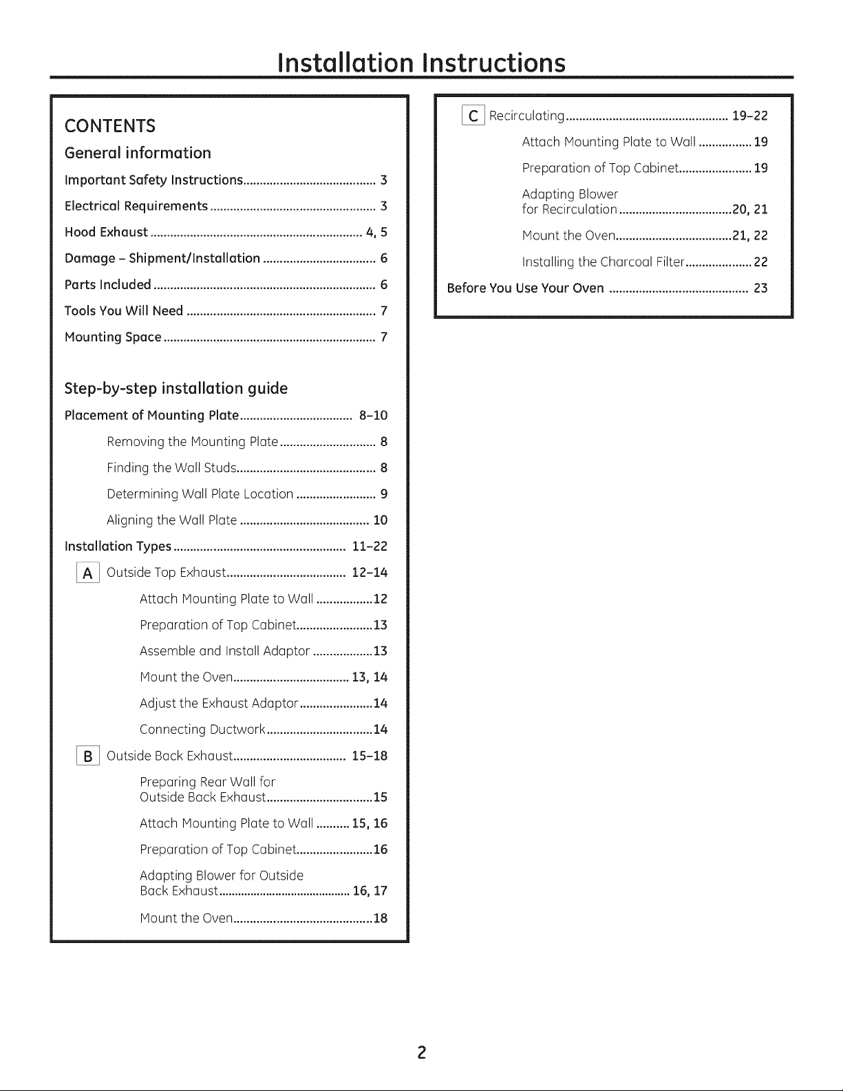
CONTENTS
General information
Important Safety Instructions ........................................ 3
Electrical Requirements .................................................. 3
Hood Exhaust ................................................................ 4, 5
Damage - Shipment/Installation .................................. 6
Parts Included ................................................................... 6
Tools You Will Need ......................................................... 7
Mounting Space ................................................................ 7
Step-by-step installation guide
Placement of Mounting Plate .................................. 8-10
Removing the Mounting Plate ............................. 8
Finding the Wall Studs .......................................... 8
Determining Wall Plate Location ........................ 9
[_ Recirculating .................................................19-22
Attach Mounting Plate to Wall ................19
Preparation of Top Cabinet ......................19
Adapting Blower
for Recirculation ..................................20, 21
Mount the Oven...................................21, 22
Installing the Charcoal Filter....................22
Before You Use Your Oven ..........................................23
Aligning the Wall Plate ....................................... 10
Installation Types .................................................... 11-22
[_ Outside Top ....................................
[_ Outside .................................. 15-18
Exhaust 12-14
Attach Mounting Plate to Wall ................. 12
Preparation of Top Cabinet ....................... 13
Assemble and Install Adaptor .................. 13
Mount the Oven ................................... 13, 14
Adjust the Exhaust Adaptor ...................... 14
Connecting Ductwork ................................ 14
Back Exhaust
Preparing Rear Wall for
Outside Beck Exhaust ................................ 15
Attach Mounting Plate to Wall .......... 15, 16
Preparation of Top Cabinet ....................... 16
Adapting Blower for Outside
Beck Exhaust .......................................... 16, 17
Mount the Oven .......................................... 18
Installation Instructions
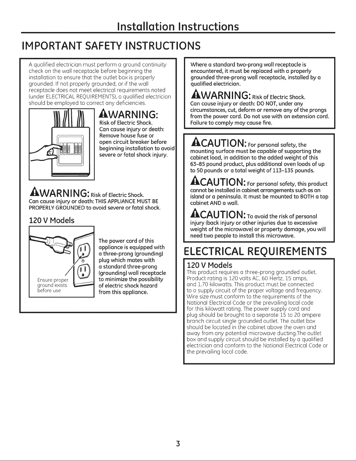
IMPORTANT SAFETY INSTRUCTIONS
A qualified electrician must perform a ground continuity
check on the wall receptacle before beginning the
installation to ensure that the outlet box is properly
grounded. If not properly grounded, or if the wall
receptacle does not meet electrical requirements noted
(under ELECTRICALREQUIREMENTS),u qualified electrician
should be employed to correct any deficiencies.
WARNING:
Riskof Electric Shock.
Can cause injury or death:
Remove house fuse or
open circuit breaker before
beginning installation to avoid
severe or fatal shock injury.
J_,VV_I_I_I I I_i!tJ: Riskof Electric Shock.
Can cause injury or death: THISAPPLIANCEMUSTBE
PROPERLYGROUNDEDto avoid severe or fatal shock.
120 V Models
The power cord of this
appliance isequipped with
a three-prong {grounding)
plug which mates with
a standard three-prong
{grounding}wall receptacle
groond ex' sE
beforeuse
to minimize the possibility
of electric shock hazard
from this appliance.
Where a standard two-prong wall receptacle is
encountered, it must be replaced with a properly
grounded three-prong wall receptacle, installed by a
qualified electrician.
AWARN ING:RiskofElectricShock.
Can cause injury or death: DO NOT,under any
circumstances, cut, deform or remove any of the prongs
from the power cord. Do not use with an extension cord.
Failure to comply may cause fire.
Ar-^_ rrlr,_!
_L,_U||U|_: For personal safety, the
mounting surface must be capable of supporting the
cabinet load, in addition to the added weight of this
63-85 pound product, plus additional oven loads of up
to 50 pounds or a total weight of 113-135 pounds.
ACAUTION: For personal safety, this product
cannot be installed incabinet arrangements such as an
island or a peninsula. It must be mounted to BOTHa top
cabinet AND awall.
ACAUTION: Toavoidtheriskofpersonal
injury Iback injury or other injuries due to excessive
weight of the microwave) or property damage, you will
need two people to install this microwave.
ELECTRICAL REQUIREMENTS
120 V Models
This product requires athree-prong grounded outlet.
Product rating is 120 volts AC, 60 Hertz, 15 amps,
and 1.70 kilowatts. This product must be connected
to a supply circuit of the proper voltage and frequency.
Wire sizemust conform to the requirements of the
National Electrical Code or the prevailing local code
for this kilowatt rating. The power supply cord and
plug should be brought to a separate lS to 20 ampere
branch circuit single grounded outlet. The outlet box
should be located in the cabinet above the oven and
away from any potential microwave ducting.The outlet
box and supply circuit should be installed by a qualified
electrician and conform to the National Electrical Code or
the prevailing local code.
3
Installation Instructions
HOOD EXHAUST
NOTE:Read these next two pages only if you plan to vent your exhaust to the outside.
If you plan to redrculate the air back into the room, proceed to page 6.
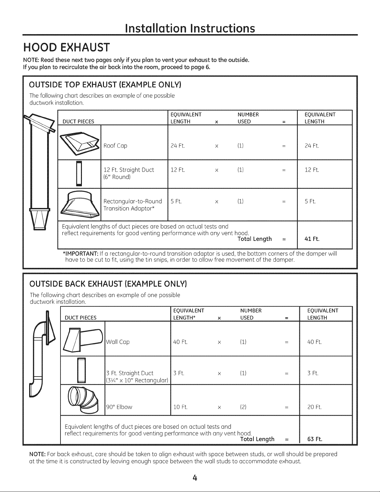
OUTSIDE TOP EXHAUST (EXAMPLE ONLY)
Thefollowing chart describes an example of one possible
ductwork installation.
EQUIVALENT NUMBER EQUIVALENT
DUCT PIECES
LENGTH x USED = LENGTH
Roof Cap
12 Ft.Straight Duct
D
Equivalent lengths of duct pieces are based on actual tests and
reflect requirements for good venting performance with any vent hood.
*IMPORTANT:If a rectangular-to-round transition adaptor is used, the bottom corners of the damper will
have to be cut to fit, using the tin snips, in order to allow free movement of the damper.
(6" Round)
Rectangular-to-Round
Transition Adaptor*
24 Ft. x (!)
12 Ft. x (!)
5 Ft. x (!)
OUTSIDE BACK EXHAUST (EXAMPLE ONLY)
The following chart describes an example of one possible
ductwork installation.
EQUIVALENT NUMBER EQUIVALENT
DUCT PIECES
LENGTH* x USED = LENGTH
Total Length
24 Ft.
12 Ft.
5 Ft.
41 Ft.
Wall Cap
3 Ft. Straight Duct
3¼" x !0" Rectangular)
40 Ft. x (!)
3 Ft. x (!)
40 Ft.
3 Ft.
[
90° Elbow
Equivalent lengths of duct pieces are based on actual tests and
reflect requirements for good venting performance with any vent hood.
NOTE:For back exhaust, care should be taken to align exhaust with space between studs, or wall should be prepared
at the time it is constructed by leaving enough space between the wall studs to accommodate exhaust.
!0 Ft. x (2)
Total Length
= 63 Ft.
4
20 Ft.
Installation Instructions
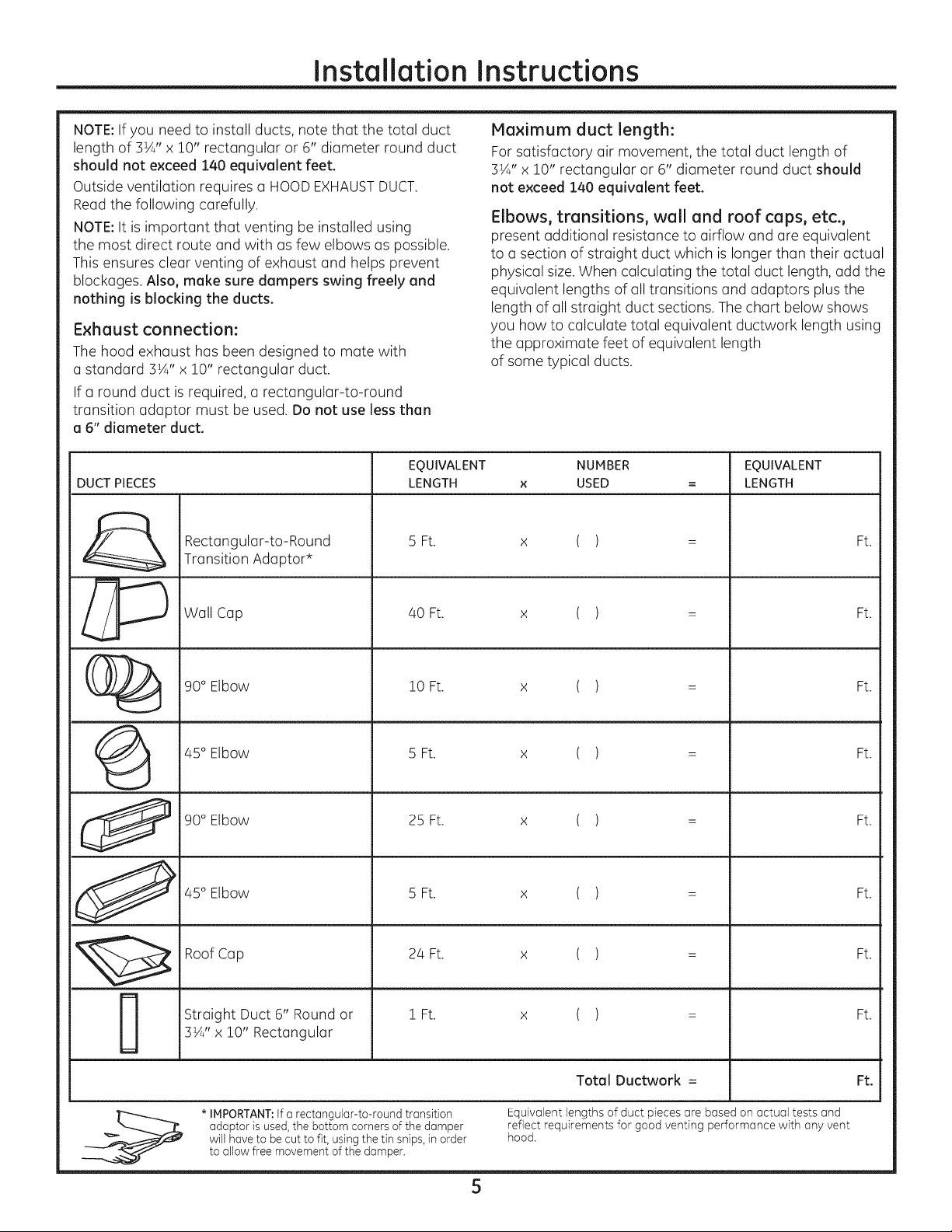
NOTE:If you need to install ducts, note that the total duct
length of 3¼" x 10" rectangular or 6" diameter round duct
should not exceed 140 equivalent feet.
Outside ventilation requires a HOODEXHAUSTDUCT.
Maximum duct length:
For satisfactory air movement, the total duct length of
3¼" x 10" rectangular or 6" diameter round duct should
not exceed 140 equivalent feet.
Read the following carefully.
NOTE:It is important that venting be installed using
the most direct route and with as few elbows as possible.
This ensures clear venting of exhaust and helps prevent
blockages. Also, make sure dampers swing freely end
nothing is blocking the ducts.
Exhaust connection:
The hood exhaust has been designed to mate with
a standard 3½" x 10" rectangular duct.
Elbows, transitions, wall and roof caps, etc.,
present additional resistance to airflow and are equivalent
to a section of straight duct which is longer than their actual
physical size.When calculating the total duct length, add the
equivalent lengths of all transitions and adaptors plus the
length of all straight duct sections. The chart below shows
you how to calculate total equivalent ductwork length using
the approximate feet of equivalent length
of some typical ducts.
If a round duct is required, a rectangular-to-round
transition adaptor must be used. Do not use less than
a 6" diameter duct.
EQUIVALENT NUMBER EQUIVALENT
DUCT PIECES LENGTH x USED = LENGTH
Rectangular-to-Round 5 Ft. ( ) Ft.
Transition Adaptor*
x
_ Wall Cap /40Ft. x ( ) : Ft.
(_ 90° Elbow 10 Ft. x ( ) = Ft.
(_ /45°Elbow 5 Ft. x ( ) = Ft.
90° Elbow 25 Ft. x ( ) = Ft.
_ /45 Elbow 5Ft. x ( ) = Ft.
Straight Duct 6" Round or 1 Ft. x ( ) = Ft.
3¼" x !0" Rectangular
Total Ductwork = Ft.
* IMPORTANT:If a rectangular-to-round transition Equivalent lengths of duct pieces are based on actual tests and
adaptor is used, the bottom corners of the damper reflect requirements for good venting performance with any vent
will have to be cut to fit, using the tin snips, in order hood.
to allow free movement of the damper.
5
Installation Instructions
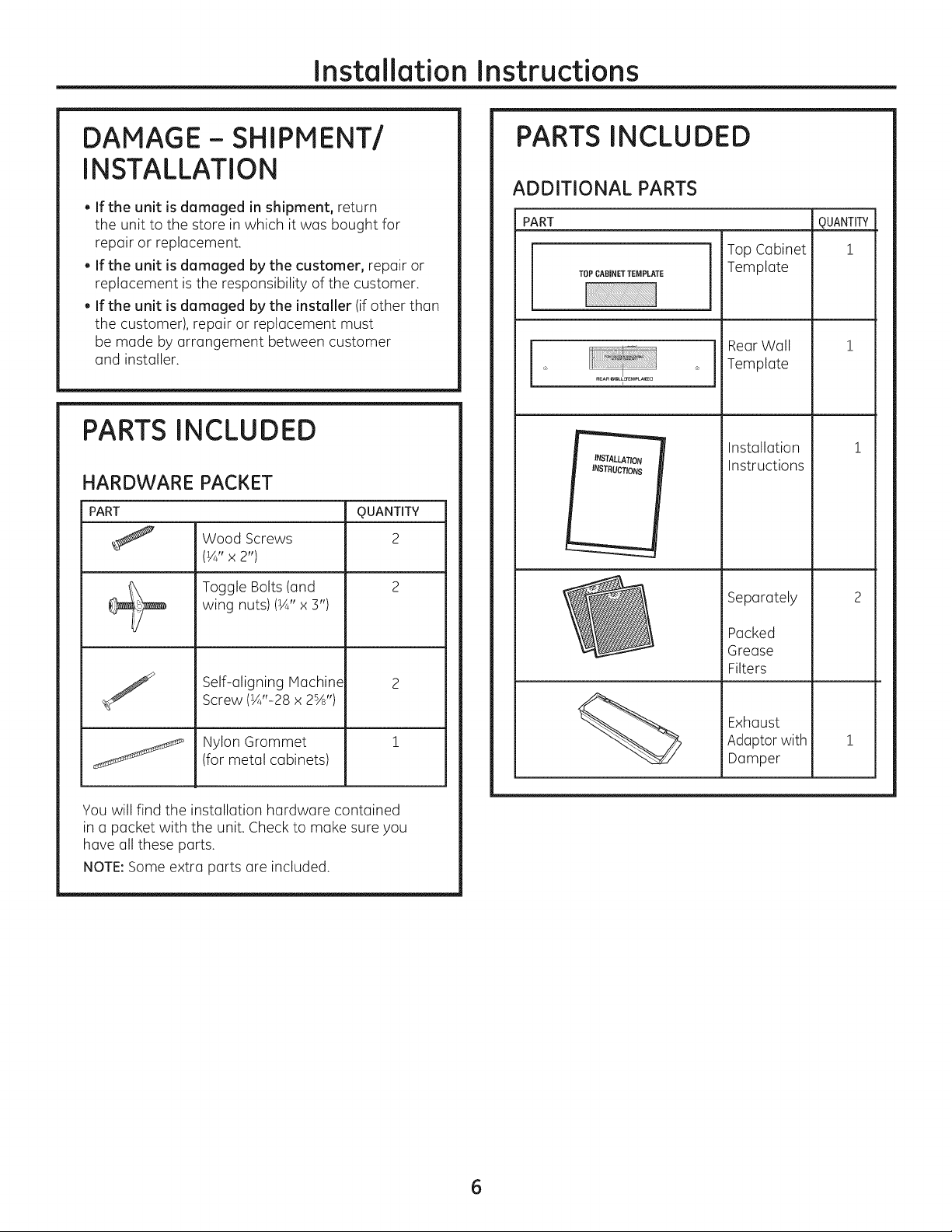
DAMAGE- SHIPMENT/
INSTALLATION
. If the unit is damaged in shipment, return
the unit to the store in which it was bought for
repair or replacement.
. If the unit is damaged by the customer, repair or
replacement is the responsibility of the customer.
. If the unit is damaged by the installer (if other than
the customer), repair or replacement must
be made by arrangement between customer
and installer.
PARTS INCLUDED
HARDWARE PACKET
PART
Wood Screws
(¼" x 2")
Toggle Bolts (and
wing nuts)(¼" x 3")
Self-aligning Machine
Screw (¼"-28 x 2%')
Nylon Grommet
(for metal cabinets)
QUANTITY
2
PARTS INCLUDED
ADDITIONAL PARTS
PART
TOPCABINETTEMPLATE
INSTALLATION
INSTRUCTIONS
Top Cabinet
Template
RearWall
Template
Installation
Instructions
Separately
Packed
Grease
Filters
Exhaust
Adoptor with
Damper
m
QUANTITY
i
i
You will find the installation hardware contained
in a packet with the unit. Check to make sure you
have all these parts.
NOTE:Some extra parts are included.
6
Installation Instructions
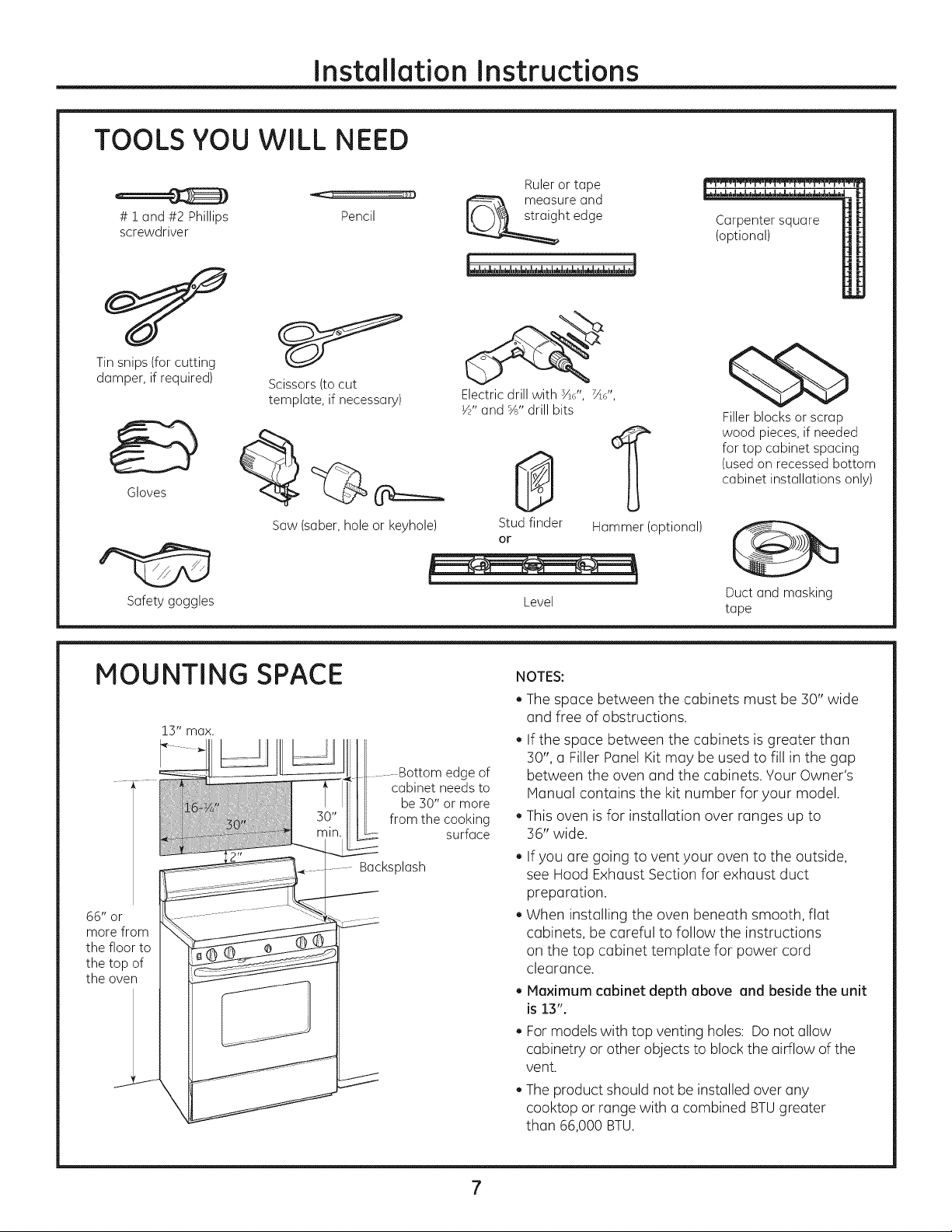
TOOLS YOU WILL NEED
# i and#2 Phillips Pencil
screwdriver
Tinsnips(for cutting
damper,if required)
Gloves
Scissors(tocut
template, if necessary)
Ruleror tape
measureand
ht edge
Electric drill with sad', 7Ad',
½" and %" drill bits
0
1
Carpentersquare
(optional)
¢5b
Fillerblocksorscrap
wood pieces,if needed
for top cabinet spacing
(usedon recessedbottom
cabinet installationsonly)
Saw(saber,holeor keyhole)
Safetygoggles
MOUNTING SPACE
66" or
morefrom
the floor to
the top of
the oven
..........Bottom edge of
cabinet needs to
be 30" or more
from the cooking
surface
Backsplash
Studfinder
or
Level
NOTES:
The space between the cabinets must be 30" wide
and free of obstructions.
If the space between the cabinets is greater than
30", a Filler Panel Kit may be used to fill in the gap
between the oven and the cabinets. Your Owner's
Manual contains the kit number for your model.
This oven is for installation over ranges up to
36" wide.
. If you are going to vent your oven to the outside,
see Hood Exhaust Section for exhaust duct
preparation.
. When installing the oven beneath smooth, flat
cabinets, be careful to follow the instructions
on the top cabinet template for power cord
clearance.
. Maximum cabinet depth above and beside the unit
is13".
. Formodels with top venting holes: Do not allow
cabinetry or other objects to block the airflow of the
vent.
. The product should not beinstalled over any
cooktop or range with a combined BTUgreater
than 66,000 BTU.
Hammer(optional)
Ductand masking
tape
Instollotion Instructions
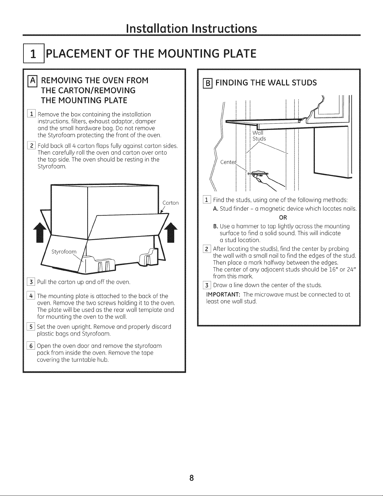
-IPLACEMENT OF THE MOUNTING PLATE
REMOVING THE OVEN FROM
THE CARTON/REMOVING
THE MOUNTING PLATE
%
Remove the box containing the installation
instructions, filters, exhaust adaptor, damper
and the small hardware bag. Do not remove
the Styrofoam protecting the front of the oven.
[]
Fold back all 4 carton flaps fully against carton sides.
Then carefully roll the oven and carton over onto
the top side.The oven should be resting in the
Styrofoam.
Styrofoam
%
Pullthe carton up and off the oven.
%
The mounting plate is attached to the back of the
oven. Remove the two screws holding it to the oven.
The plate will be used as the rear wall template and
for mounting the oven to the wall.
%
Setthe oven upright. Remove and properly discard
plastic bags and Styrofoam.
\
[_ FINDING THE WALL STUDS
Wall
Studs
Cente_
[_ Findthe studs, using one of the following methods:
A. Stud finder - a magnetic device which locates nails.
OR
B. Use a hammer to tap lightly across the mounting
surface to find a solid sound. This will indicate
a stud location.
[_ After locating the stud(s),find the center by probing
the wall with a small nail to find the edges of the stud.
Then place a mark halfway between the edges.
The center of any adjacent studs should be 16" or 24"
from this mark.
[_ Draw a line down the center of the studs.
IMPORTANT: The microwave must be connected to at
least one wall stud.
%
Open the oven door and remove the styrofoam
pack from inside the oven. Remove the tape
covering the turntable hub.
8
Installation Instructions
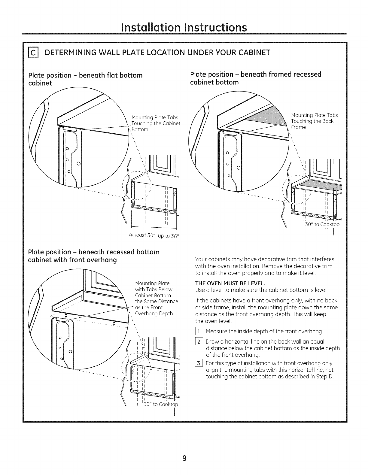
DETERMINING WALL PLATE LOCATION UNDER YOUR CABINET
Plate position - beneath flat bottom
cabinet
o
At least 30", up to 36"
MountingPlateTabs
Touching theCabinet
:.Bottom
Plate position - beneath framed recessed
cabinet bottom
Mounting Plate Tubs
Touching the Back
Frame
II "30" to Cooktop
i ,, I
Plate position - beneath recessed bottom
cabinet with front overhang
MountingPlate
with TabsBelow
CabinetBottom
the SameDistance
asthe Front
'....Overhang Depth
..
..
-..
0
0
C
;0" to Cooktop
Your cabinets may have decorative trim that interferes
with the oven installation. Remove the decorative trim
to install the oven properly and to make it level.
THE OVEN MUST BE LEVEL.
Use (] level to make sure the cabinet bottom is level.
If the cabinets have (]front overhang only, with no back
or side frame, install the mounting plate down the some
distonce us the front overhung depth. This will keep
the oven level.
[_ Measure the inside depth of the front overhung.
[_ Draw (] horizontal line on the buck wall tin equal
l
distance below the cabinet bottom usthe inside depth
of the front overhung.
[_ For this type of installation with front overhung only,
align the mounting tubs with this horizontal line,not
touching the cabinet bottom us described in Step D.
I
9
Installation Instructions
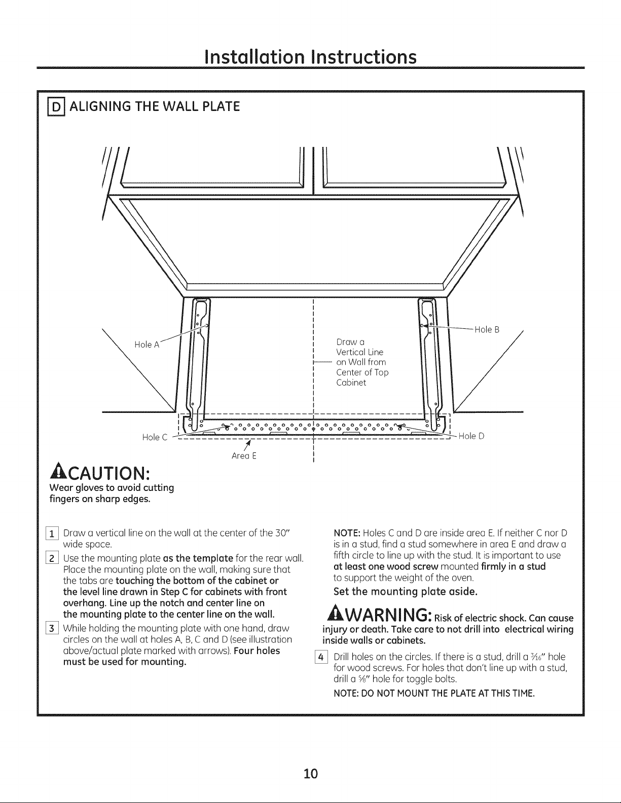
_ ALIGNING THE WALL PLATE
Hole
I
I
Hole C
4 T
AreaE J
ACAUTION'.
Wear glovestoavoidcutting
fingerson sharpedges.
[_ Drawa vertical line on the wall at the center of the 30"
wide space.
[_ Usethe mounting plate as the template for the rear wall.
Placethe mounting plate on the wall, making sure that
the tabs are touching the bottom of the cabinet or
the level line drawn in Step C for cabinets with front
overhang. Line up the notch and center line on
the mounting plate to the center line on the wall.
[_ While holding the mounting plate with one hand, draw
circles on the wall at holes A, B,Cand D(see illustration
above/actual plate marked with arrows). Four holes
must be used for mounting.
Draw o
Vertical Line
b---- on Wall from
Center of Top
Cabinet
olo
I
I
NOTE:Holes Cand D are inside area E.If neither C nor D
isin astud, find a stud somewhere in area Eand draw a
fifth circle to line up with the stud. It is important to use
at least one wood screw mounted firmly in a stud
to support the weight of the oven.
Set the mounting plate aside.
A WARNING:Riskofelectricshock.Cancause
injury or death. Take care to not drill into electrical wiring
inside walls or cabinets.
[_ Drill holeson the circles. If there is a stud, drill a sad'hole
for wood screws. For holes that don't line upwith a stud,
drill a %" hole for toggle bolts.
NOTE:DONOTMOUNTTHEPLATEAT THISTIME,
10
Installation Instructions
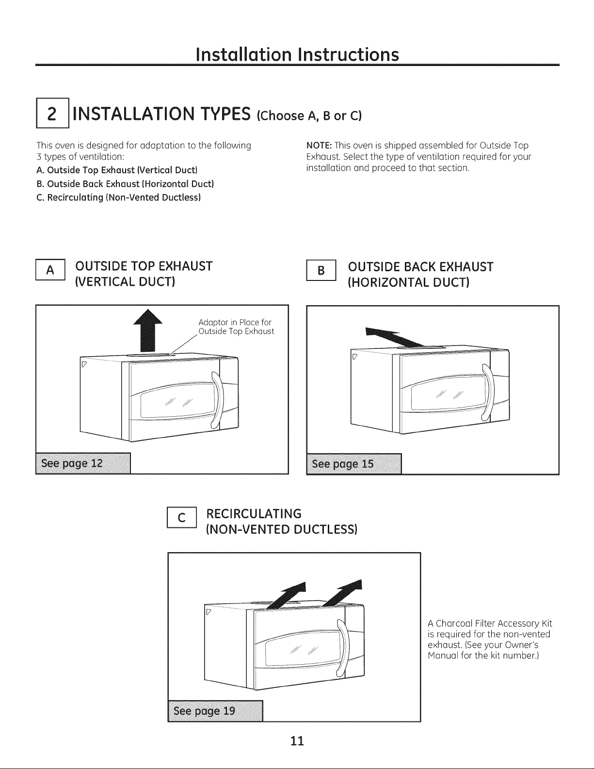
INSTALLATION TYPES
This oven is designed for adaptation to the following
3 types of ventilation:
A. Outside Top Exhaust (Vertical Duct)
B. Outside Back Exhaust (Horizontal Duct)
C. Recirculating (Non-Vented Ductless)
J_ OUTSIDE TOP EXHAUST
(VERTICAL DUCT)
Adaptor in Ploce for
Outside Top Exhaust
(Choose A, B or C)
NOTE:This oven is shipped assembled for Outside Top
Exhaust. Select the type of ventilation required for your
installation and proceed to that section.
r_ UTSIDE BACK EXHAUST
(HORIZONTAL DUCT)
1_ RECIRCULATING
(NON-VENTED DUCTLESS)
A Charcoal Filter Accessory Kit
is required for the non-vented
exhaust. (Seeyour Owner's
Manual for the kit number.)
11
Installation Instructions
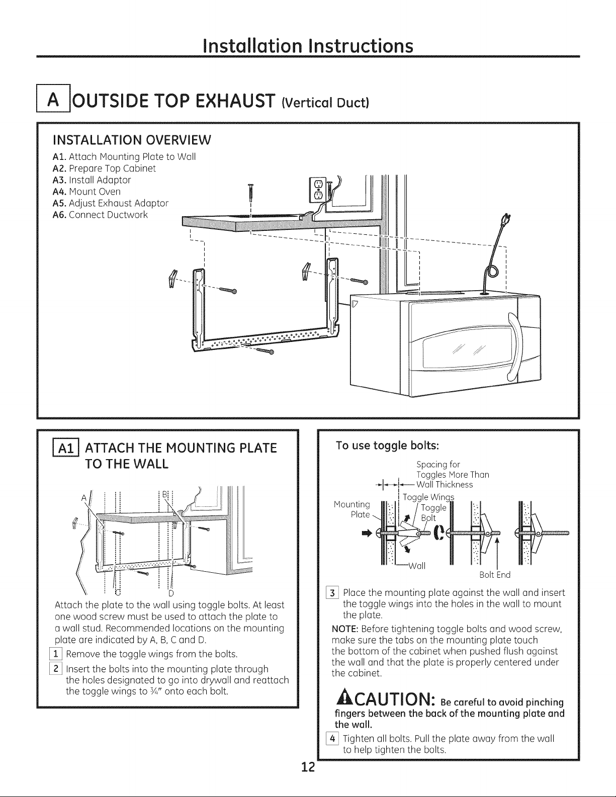
IA-IOUTSIDE TOP EXHAUST (Vertical Duct)
INSTALLATION OVERVIEW
AI. Attach Mounting Plate to Well
A2. Prepare Top Cabinet
A3. Install Adaptor
A4. Mount Oven
AS.Adjust Exhaust Adaptor
A6. Connect Ductwork
ATTACH THE MOUNTING PLATE
TO THE WALL
i B
Attach the plate to the well using toggle bolts. At least
one wood screw must be used to attach the plate to
a wall stud. Recommended locutions on the mounting
plate are indicated by A, B,C and D.
[_ Remove the toggle wings from the bolts.
[_ Insert the bolts into the mounting plate through
the holes designated to go into drywall end reattach
the toggle wings to ¾" onto each bolt.
To use toggle bolts:
Spacing for
Toggles More Then
"_l_,-k_-- Wall Thickness
Mounting
i Toggle Wing_
Bolt End
[_ Place the mounting plate against the wall and insert
the toggle wings into the holes in the wall to mount
the plate.
NOTE:Before tightening toggle bolts and wood screw,
make sure the tabs on the mounting plate touch
the bottom of the cabinet when pushed flush against
the wall and that the plate is properly centered under
the cabinet.
LIILI_,I"_UIIIIJI_I: Be careful to avoid pinching
fingers between the back of the mounting plate and
the wall.
[_ Tighten all bolts. Pull the plate away from the wall
to help tighten the bolts.
12
Installation Instructions
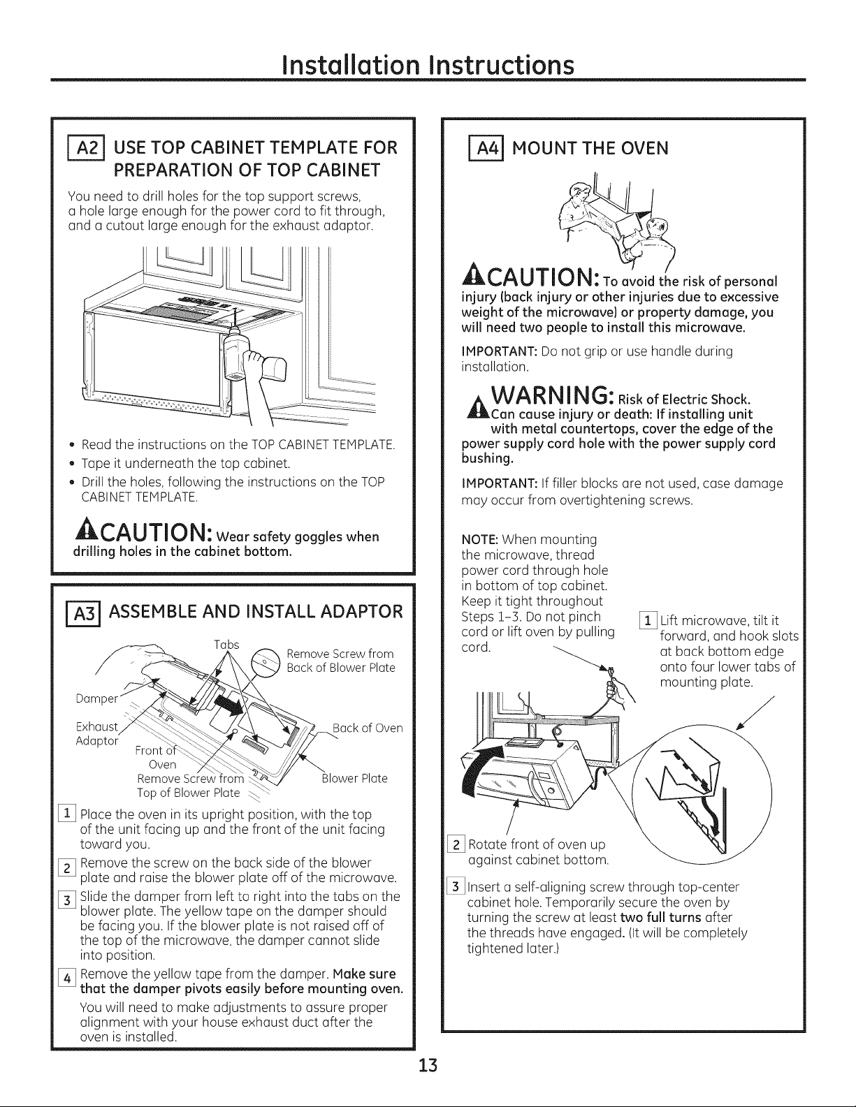
_USE TOP CABINET TEMPLATE FOR
PREPARATION OF TOP CABINET
You need to drill holes for the top support screws,
a hole large enough for the power cord to fit through,
and a cutout large enough for the exhaust adaptor.
. Read the instructions on the TOPCABINETTEMPLATE.
. Tape it underneath the top cabinet.
Drillthe holes, following the instructions on the TOP
CABINETTEMPLATE.
A,--^l i-rill,!
Wearsafetygoggleswhen
drilling holes in the cabinet bottom.
FA=-_ASSEMBLE AND INSTALL ADAPTOR
Tabs
Back of Blower Plate
_ Remove Screw from
/-j,
Da
_ MOUNT THE OVEN
CAUTI e riskofpersonal
injury (back injury or other injuries due to excessive
weight of the microwave) or property damage, you
will need two people to install this microwave.
IMPORTANT:Do not grip or use handle during
installation.
A WA RNING:RiskofElectricShock.
Can cause injury or death: If installing unit
with metal countertops, cover the edge of the
power supply cord hole with the power supply cord
bushing.
IMPORTANT:If filler blocks are not used, case damage
may occur from overtightening screws.
NOTE:When mounting
the microwave, thread
power cord through hole
in bottom of top cabinet.
Keep it tight throughout
Steps 1-3. Do not pinch
cord or lift oven by pulling
cord.
[_ Lift microwave, tilt it
forward, and hook slots
at back bottom edge
onto four lower tabs of
mounting plate.
Exhaust_q_-_
Adaptor" _ "'_C_-:
[_ Placethe oven in its upright position, with the top
of the unit facing up and the front of the unit facing
toward you.
[_ Remove the screw on the back side of the blower
plate and raise the blower plate off of the microwave.
[_ Slide the damper from left to right into the tabs on the
blower plate. The yellow tape on the damper should
be facing you. If the blower plate is not raised off of
the top of the microwave, the damper cannot slide
into position.
[_ Remove the yellow tape from the damper. Make sure
that the damper pivots easily before mounting oven.
You will need to make adjustments to assure proper
alignment with your house exhaust duct after the
oven is installed.
Front o'f_
Oven
Remove Screw
Topof BlowerPlate
¢ Back of Oven
__wer Plate
[_ Rotate front of oven up
against cabinet bottom.
[_ Insert a self-aligning screw through top-center
cabinet hole. Temporarily secure the oven by
turning the screw at least two full turns after
the threads have engaged. (Itwill be completely
tightened later.)
13
Installation Instructions
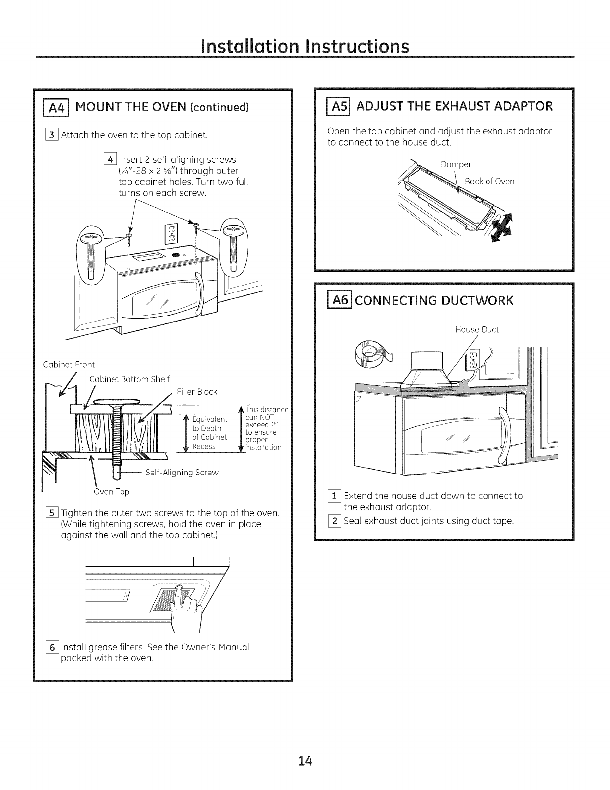
_ MOUNT THE OVEN Icontinued}
[_ Attach the oven to the top cabinet.
[_ Insert 2 self-aligning screws
(¼"-28 x 2 %') through outer
top cabinet holes.Turn two full
turns on each screw.
Cabinet Front
Cabinet Bottom Shelf
FillerBlock
_=5] ADJUST THE EXHAUST ADAPTOR
Open the top cabinet and adjust the exhaust adaptor
to connect to the house duct.
Damper
Back of Oven
_6] CONNECTING DUCTWORK
House Duct
--_--Equivalent / can NOT
I i° Depth /to ensure
I of Cabinet |proper
_'nstallation
-- Self-Aligning Screw
Oven Top
[] Tighten the outer two screws to the top of the oven.
(While tightening screws, hold the oven in place
against the wall and the top cabinet.)
..............................................................................................111 i _],
[_ Install grease filters. Seethe Owner's Manual
packed with the oven.
,/
_This distGnce
exceed 2"
[_ Extend the house duct down to connect to
the exhaust adaptor.
[_ Seal exhaust duct joints using duct tape.
14
Installation Instructions
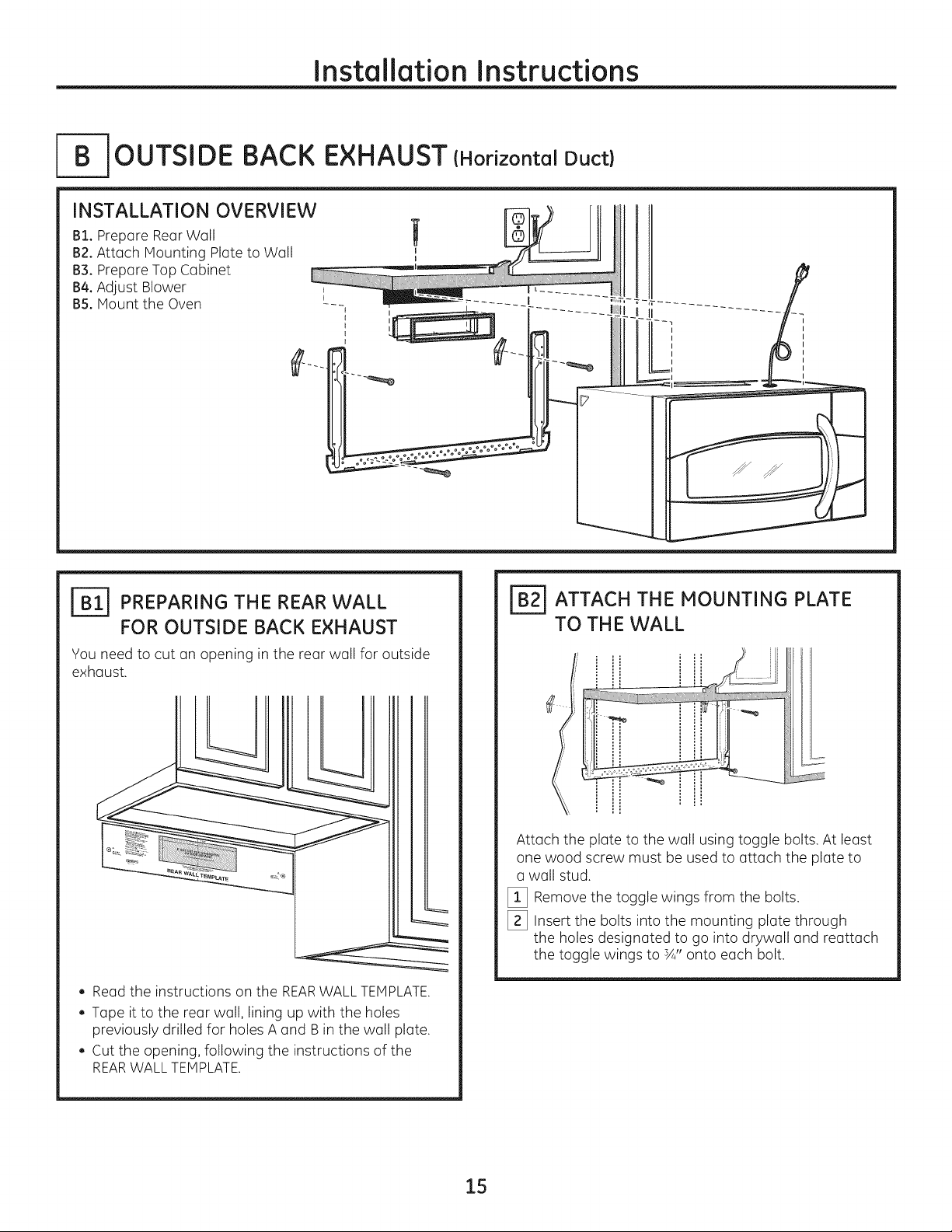
_--B-JOUTSIDE BACK EXHAUST (Horizontal Duct)
INSTALLATION OVERVIEW
B1. Prepare Rear Wall
B2.Attach Mounting Plate to Wall
B3°Prepare Top Cabinet
B4.Adjust Blower ,
BS.Mount the Oven --- _i_
.L
12
J_ PREPARING THE REAR WALL
FOR OUTSIDE BACK EXHAUST
You need to cut an opening in the rear wall for outside
exhaust.
, Read the instructions on the REARWALLTEMPLATE.
, Tape it to the rear wall, lining up with the holes
previously drilled for holes A and B in the wall plate.
, Cut the opening, following the instructions of the
REARWALL TEMPLATE.
FB_ ATTACH THE MOUNTING PLATE
TO THE WALL
!i
,, i......3'!! i
Attach the plate to the wall using toggle bolts. At least
one wood screw must be used to attach the plate to
a wall stud.
[_ Remove the toggle wings from the bolts.
[_ Insert the bolts into the mounting plate through
the holes designated to go into drywall and reattach
the toggle wings to sA"onto each bolt.
15
 Loading...