

Page 1
www. GEAppliances.com
Safety Information ........ 9 3
Operating/Care and
Cleaning Instructions
Charcoal Filter. .............. 5
Grease Filter . ............... 4
Hood Light ................. 5
Hood Surfaces ............... 5
Controls .................... 4
Installation Instruotions ...6-16
Consumer Support
Consumer Support . . .Back Co_er
Warranty .................. ] 9
_ 32 7-Reci_ulation only
q;338" _nt @tions only
q;34 7* _nt & Reci_ulation
options
q;36 7* _nt & Reci_ulation
options
RN328-Reci_ulation only
CERTIFIED
Write the model and serial numbers here:
Model #
Serial #
Ybu can find them on a label on the
back wall ol the hood.
7ZTZTZTZTZTZ;;
164D4290P393 49-80242 12-03 JR
Page 2
IMPORTANTSAFETYINFORMATION.
READALLINSTRUCtiONSBEFOREUSING.
SAFETYPRECAUtiONS
WARNING-TOREBUCETHERISKOFFIRE,
ELECTRICSHOCKORINJURY TOPERSONS,OBSERVE
THEFOLLOWING:
3.. Use this unit onh in the rammer intended
b_ the n]anufiJcture_: Ifmu hme questkms,
contact the l/l_lJltlfilC[tlreE
B. Before servicing or cleaning unit, swimh power off
at selMce panel and lock the service disconnecting
means to pre_ent power fl'om being swimhed on
accidentally. \_]len the service disconnecting
means cmmot be locked, securel) tilsmn a
prominent _mling de_ice, such as a my, to
the selMce panel.
C. Do not use this trait with an\ solid-stare speed
conm)l de\ice.
D. If using a cord connection kit, use one with mnge
hood cord4"onnectkm kitjXHCl that has been
WARNING- TOREBUCETHERISKOF
A RANGETOPGREASEFIRE:
A. Ne_vr leme surfitce units unattended at high
settings, goih)_e_ cause smoking and gTeas)
spilloxe_ that ma) ig_lim. Heat oils slowh on low
or medium settings.
B. AI\\rIIVS[[lI'I1 hood ON _\hen cooking at high heat
or when cooking flaming ti)()(ts.
C. Clean ventilating fires fl'equentb'. (',Tease shouM
not be allowed to accumulate on tim or filte/:
D. Use proper pail size. AE_m's use cookwtwe
appr_)priate for the size of the surfilce element.
WARNING-TOREBUCETHERISKOFnRE,
ELECTRICSHOCKORINJURY TOPERSONS,OBSERVE
THEFOLLOWING:
A. Installation work and electrical wMng must be
imvsfigamd and %und acceptable %r use \vifll
this model range hood.
E. This unit must be gTounded.
CAUTION-FORCENERALVENT,_T,NGUSE
ONLYO0 NOTUSETOEXHAUSTHAZARDOUSOR
EXPLOSIVEMATERIALSAND VAPORS,
WARNING- TOREBUCETHERISKOF
INJURY TOPERSONSIN THEEVENTOFARANGETOP
GREASEFIRE,OBSERVETHEFOLLOWING*."
A. SMOTHER FIAMES with a close-fitting lid,
cookie sheet or metal tra), then turn off file
burnec BE CAREFUL TO PREVENT BURNS.
If the flan/es do not g_) Otlt immediate b
EVACUATE AND CAI i_ THE FIRE
DEPARTMENT,
B. NEVER PICK UP A FI AMING g_N--
_)tl mm be burned.
done b) qualified pe_on (s) in accordance wifll
all applicable codes and stan&Jrds, inchlding
fire-rated construction.
B. Sttfl]cient air is needed for proper combustkm
and exhausting of gases through tile title
(chimne)) of fllel burning equipment to pre_ent
back drafting. Follow the heating equipment
manuiilcturer's guideline ml(t safbh standards
such as those published b_ the National Fire
Protection Association (NFE_), the American
Socie F fi)r Heating, Refl'igemfion mid Air
Conditioning Eng-ineers (ASHRAE) and the
local code authorities.
C. \_]len cutting or drilling into \V_l]lor ceiling, do
not damag> elecu'ical wMng and other hkMen
utilities.
D. Ducmd fires must a]\\rtlVS be venmd to the
otttdoors.
C. DO NOT USE _ATER, inclucfing wet
dishcloflls or towels--a violent stemn
explosion will result+
D. Use all extinguisher ONIYifl
1. Y)u know you hme a Class ABC exfinguisheI;
and you ahead) know how to operate it.
2. The fire is small and contained in the m'ea
_dlere it started.
3. The fire department is being called.
4. Y)u call fight file fire wifll vottr back to all exit.
* Based on "Kimhen Firesafet) Tips" published
b_ NFE_.
READANDFOLLOWTHISSAFETYINFORMATIONCAREFULLY.
WARNING-TOREBUCETHERISKOFeRE,
USEONLYMETALDUCTWORK.
Do not attempt to repair or replace an) part of
your hood unless it is specifical]) recommended in
this guide. NI other seT\icing shouM be referred to
a quNified mchnician.
READANDSAVETHESEINSTRUCtiONS
Page 3
INSTRUCTIONS DE SECURITE IMPORTANTES.
LISEZ TOUTES LES INSTRUCTIONS AVANT D'UTILISER.
PRE-CAUtiONSENMATIEREBESE-CURITE-
AVERTISSEMENT-pourRtDUIRELE
RISQUED'INCENDIE,DESECOUSSE_'LECTRIQUEOUDE
BLESSURECORPORELLE,OBSERVEZLESPRECAUTIONS
SUIVANTES:
A. N'utilisez cet apparel[ que de I_ mani_re pr&'ue
par le f_tbficant. SJ _ous mez des questions, appelez
le £_blicant.
B. Avant de r@m'er ou de netto} er _otre appm'eJl,
d_branchez [e c!)uran t art nixeau (lit panneau
de service et xerrouillez les m(_canismes de
d_bmnchement de service pour _xitei"tout
branchelllellt accidentel au cottrallt. 81 "_OtlSne
pomez pas xerrouiller [es m_canisn-les de
debmnchement de service, attachez soigneusement
ttll mertissement bien visible, comme une etiquette,
art pmmeau de service.
C. N'udlisezjamais cet appareil axec un m(_canisme
de r_glage de [a vitesse fisemi-conducteurs.
D. Si xous utilisez ['ensemble de cordon de
mccordement, utilise seulement mec I'ensemble de
cordon de raccordement pour hotte,]XHC1. Suite _
ttll examen technique, I'articleJXHC1 s'est ax(!r(!
compadl)le mec ce module de hotte.
E. Cet appareil dolt &re bien mis k la terre.
ATTENTION- UNIOUEVENT,_USAGEOE
VENTILATIONGENERALE.N'UTILISEZJAMAtS POUR
L'E-CHAPPEMENTDEMATIERESETDE VAPEURS
EXPLOSIVES,
AVERTISSEMENT-pourR_DUIRELE
RISQUEDEBLESSURECORPORELLESI DELAGRAISSE
PRENDFEUSURLASURFACEDECUISSONDUFOUR,
SUIVEZLESINSTRUCTIONSSUIVANTES*:
A. I_Tt-)UFFEZ I,ES HAMMES :aec un cou\_rcle qui
comient, une t61e 5 biscuits ou un plamml en m&al,
puis &eignez le b_01eur EMTES BIEN ATTENTION
DE NE PAS VOUS BRUI,ER. Si les flammes ne
s'&eignent pas imm&liamment, SORTEZ ET
APPEI,EZ I,ES POMPIERS.
B. NE D1_PIA(_EZ JA_tMS UNE (ASSEROI I_E QUI
H AMBE - \i)us p(/u_ez _(/us brfller
C. N'UTII,ISEZJAMAIS D'E&U, en particulier de
serxietm ou de chitton mouilld - i/se produira une
explosion violente de x;/peur brQlante.
D. N'UTIHSEZ UN EXTINCTEUR que si :
1. \i)us avez un extincteur de classe ABC et vous
smez comment I'utiliser;
2. Le lieu est rdduit et confine ::_['endroit (/fl i[ a
commencd;
3. \i_us m:ez d{j21appeld les pompiers;
4. \i_us combattez les flammes en tournant le dos 2l
rifle sortie.
* Base sur I'om rage intitul(_ <<KitchenNre Sale V Tips,,
publi(_ par [a NFPA.
AVERTISSEMENT-R_DU,SEZt_
RISQUED'UN FEUDE GRAISSESURLA SURFACEDE
CUISSONDUFOUR:
A. Ne laissez.jam_/is Stillssurxvillance les unit& de
cuisson de surfiice :?_une temI)dmtm'e dle_('e, i,e
bouill(mnement occasi(mne des d_bordements
lmnants et graisseux qui peuvent prendre Ieu.
ChauJlez _'_leu doux les substances huileuses,
_tvec un r('gkNe bas OL1 lll()}ell.
B. Mettez toujours [a hotte en marche quand \_ms
cuisinez 2_haute tempdratm'e ou quand xx)us cuisinez
des _diments qui ont des tlammes.
C. Netto}ez les m&anismes de xenfilation
fl'dquemment. II ne flint pas pem/em'e une
accumulation de gr_isse sur [e xentilatem" ou
sur le filtre.
D. Utilisez une casserole de bonne mille. Utilisez
tott,jom's un ustensile de cuisine qui conviemm ml
diam&re de 1'4[4ment de cuisson.
AVERTISSEMENT-_ouRR_DUIRE
RISQUED'INCENDIE,DESECOUSSE_'LECTRIQUEOUDE
BLESSURECORPORELLE,OBSERVEZLESPR_'CAUTIONS
SUIVANTES:
A, \i)us de_ez fbire exdcuter tousles trm_mx
d'installation et de c_blag-e _lectfique par une
personne qualifi(_e, c(/n_brm(_ment a tOilS[es codes
et les normes en viguem; en paruculier ceux de
construction relatifi; aux incendies.
B. Vous dex_'zassez d'air pour moir une bonne
combustion et pennettre I'('vacuation des gaz pal: le
conduit de chemin(_e d u mat(_del de combusuon du
(_rburm_t, afin d'&iter tout retour d'air Sui\vz les
directives du li_bricant de matdriel de combustion et
les normes de sdctnJtd comme celles publides par [a
National Fire Protection Assodation (NFPA),
I'Amedc_m Socie b lot Heating, Refiigerafion and
Nr Conditioning Engineers (ASHRkE), ainsi que les
modalitds des codes Iocaux.
C, Si vo/1s fhites 1111trt)tt or1 tllle ()tl\el:ttlre dans 1111111111"
Ott t111plalond, n'endommagez pas les lils dlectfiques
et les autres installations cachdes de selMce public.
D. Vous devez toujom's alimenter les _,_ntilateuI_ (lmls
[es c(/ndxlits en air en provenance de Fext('riem:
AVERTISSEMENT-_ouRR_DUIRE
LERISQUED'INCENDIE,N'UTILISEZQUEDESCONDUITS
ENMETAL
N'ess_}ezjmn_fis de remplacer (/tl de r@_rer un
_ldment de votre hotm si le present manuel ne le
I'ect)ml_lalldepas expressdment. Tout atltre entretien
doit _)tre effectual par un technicien qualifid.
LISEZETSUIVEZATTENtiVEMENTCESINSTRUCtiONS.
LISEZETCONSERVEZCESINSTRUCTIONS 3
Page 4
Usingthe hoodcontrols.
Throughout this manual, features and appearance may vary from your model.
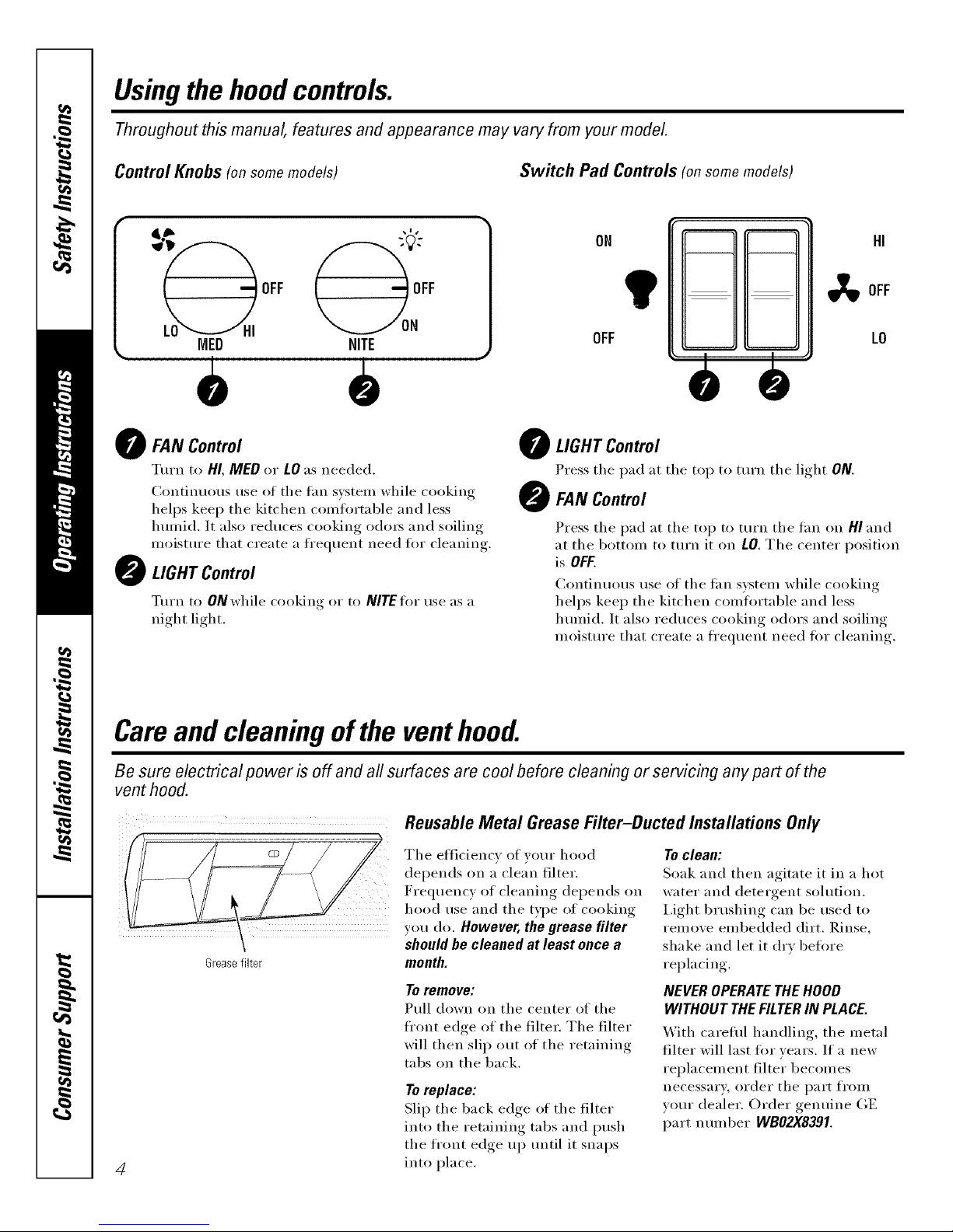
Control Knobs (onsomemodels) Switch Pad Controls (onsomemodels)
"._ "" 1
OFF OFF
ON
IVIED NITE OFF
!"
HI
OFF
LO
0
FAN Control
Turn to HI, MED or LO as needed.
Continuous use of the tim svsteln while cooking
helps kee I) the kitchen condin'table and less
lmmid. It also reduces cooking odors and soiling
moisture that create a fl'equent need fin" cleaning.
LIGHT Control
Turn to 0Nwhile cooking or to NITEfor use as a
night light.
O LIGHT Control
Press the pad at the top to tm'n the light ON.
FAN Control
Press the pad at the top to mrn the tim on HI and
at the bottom to tm'n it on LO. The center position
is OFF.
Continuous use of the tan system while cooking
helps kee I) the kitchen comfln'table and less
hmnid. It also reduces cooking odors and soiling
moistm'e that create a fl'equent need tOT cleaning.
Careand cleaning of the venthood.
Be sure electrical power is off and all surfaces are cool before cleaning or servicing any part of the
vent hood.
Greasefilter
4
Reusable Metal Grease Filter-Ducted Installations Only
The efficiency of )ore" hood
depends on a clean filter.
Fre(luenc_,, of cleaning, dei)ends on
hood tlse and the tx,])e of cooking
you do. However, the grease filter
should be cleaned at least once a
month.
Toremove:
Pull down on the center of the
fl'ont edge of the filter. The filter
will then slip out of the retaining
robs on the back.
Toreplace:
Slip the back edge of the filter
into the retaining tabs and push
the fl'ont edge up tmtil it snaps
into place.
To clean:
Soak and then agitate it in a hot
water and detergent solution.
I,ight b_ushing can be used to
remove embedded dirt. Rinse,
shake and let it dry befln'e
replacing.
NEVER OPERATE THE HOOD
WITHOUT THEFILTER IN PLACE.
With careful handling, the metal
filter will last for years. If a new
replacement filter becomes
necessary, order the part from
w)ur dealer. Order genuine GE
part ntli//ber WBO2X8391.
Page 5
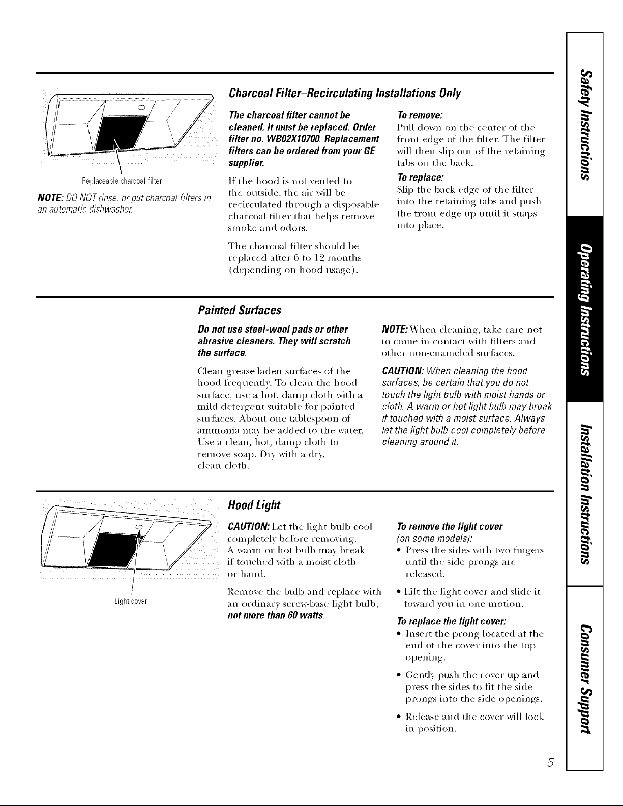
Replaceablecharcoalfilter
NOTE: DONOTrinse, or put charcoal filters in
an automatic dishwasher
Charcoal Filter-Recirculating Installations Only
The charcoal filter cannot be
cleaned. It must be replaced. Order
filter no. WBO2XI0700. Replacement
filters can be ordered from your GE
supplier.
If the hood is not vented to
the outside, the air will be
recirculated through a disposable
charcoal filter that helps reinove
Sil/oke and odors.
Toremove:
Pull down on the center of the
fl'ont edge of the filte_; The filter
will then slip out of the retaining
tabs on the back.
Toreplace:
Slip the back edge of the filter
into tile retaining tabs and push
the fl'ont edge up until it snaps
into place.
The charcoal filter should be
replaced after 6 to 12 months
(depending on hood usaoe,_ ).
Painted Surfaces
Do not use steel-wool pads or other
abrasive cleaners. They will scratch
the surface.
Clean grease-laden surlhces of the
hood fl'equently: To clean the hood
surtace, use a hot, damp cloth with a
mild detergent suitable tot painted
surtaces. About one tablespoon of
ammonia mav be added to the water.
Use a clean, hot, damp cloth to
relnove soap. Dry with a dry;
clean cloth.
NOTE:_hen cleaning, take care not
to come in contact with filters and
other non-enameled surfaces.
CAUTION:When cleaning the hood
surfaces, be certain that you do not
touch the light bulb with moist hands or
cloth.A warm or hot light bulb may break
if touched with a moist surface. Always
let the light bulb cool completely before
cleaning around it.
Lightcover
Hood Light
CAUTION:I,et tile light bulb cool
completely belm'e removing.
A warm or hot bulb may break
if touched with a moist cloth
or hand.
Remove the bulb and replace with
an ordinary scrm_q)ase light bulb,
not more than 60 watts.
Toremove the light cover
(on some models):
• Press the sides with two finge_
until the side prongs are
released.
• i,ift tile light cover and slide it
toward _o/i in one illotion.
Toreplace the light cover:
• Insert the prong located at the
end of the cover into the top
opening.
• Gently push the cover up and
press the sides to fit the side
prongs into the side openings.
• Release and the cover will lock
in position.
5
Page 6

IInsta''a:'°nnstru0t,onsI"an°e"°°'I
Questions?visitourWebsiteat: www.geappliances.com orCarlGEAnswer Center at 800.626.2000 [
BEFORE YOU BEGIN
Read these instructions completely and carefully,
• IMPORTANT - S.,ethese
instructions fin" local inspector's use.
• IMPORTANT - Obse,,e.U
governing codes and ordinances.
• Note to Installer - Be sure to leave these
instructions with tile Consumer.
• Note to Consumer - Kee I) these instructions
for flffure reference.
• Skill level - Installation of this appliance requires
basic mechanical and electrical skills.
• Completion time - 30 minutes-3 horn's
° Proper installation is tile responsibility of tile
installe_:
° Product taihu'e due to improper installation is not
covered trader tile _'_rrantv.
FOR YOUR SAFETY:
WARNING - Beiore beginning the
installation, switch power off at service panel and lock
the service disconnecting means to prevent power
fl'om being switched on accidentally. When the service
disconnecting means cannot be locked, secm'elv
fasten a prominent warning device, such as a tag,
to the service panel.
OPTIONAL POWER CORD KIT JXHC1
An optional Power Cord Connection Kit, model
JXHC1, is awfilable at extra cost from vom" GE
supplier Ira" installation using a standard 3-prong,
grounded wall outlet. Follow the Installation
Instructions packed with tile kit to connect tile power
cord to tile range hood.
DUCTWORK REQUIREMENTS
NOTE: Read the ductwork sections tufty if you do not
have existing ductwork. If you have existing ductwork,
skip to the "Damage" section mid proceed.
Tile venting system must exhaust to tile outside.
This hood can be xented xerticall)through upper
cabinets or hofizoi_tallv thI'oU,d/an outside wall.
Ductwork is not included.
Exhaust connection:
Tile hood exhaust has been designed to mate with
standard 3¼" x 10" rectangular ducting or 7" diameter
round ducting.
If a 6" round duct is required, a rectangula>to-ro/md
transition adaptor must be used*. Do not use less thm_
a 6" dimneter duct.
Maximum duct length:
For satisfhctory air movement, tile total duct length
of a 3V(' x 10" rectangular, 6" or 7" diameter to/rod
duct should not exceed 65 equivaJent feet. See the
WORKSHEET-CALCULATE TOTAL EQUIVALENT
DUCTWORK LENGTH section.
NOTE: It is important that ducting be installed using
tile most direct route and with as few elbows as possible.
This ensm'es clear venting of exhaust and helps prevent
blockages. Also, mane sure dmnpers swing freely and
nothing is blocking the ducts.
Elbows, transitions, wall and roofcaps, etc.,
present additional resist;race to airflow and are
equivalent to a section of straight duct longer than their
actual physical size. When calculating the total duct
length, add the equivalent lengths of all transitions and
adaptors plus the length of all straight duct sections. The
charts on tile ti)llowing pages show you how to calculate
total equivalent ductwork length using tile approximate
teet of equivalent length of some typical ducts.
* IMPORTANT: If a rectangula>to-
to/rod transition adaptor is used, tile
bottom corners of tile damper will
have to be cut to fit, using tile fin
snips, in order to allow fl'ee
movement of tile dampe_:
Equivalent lengths of duct pieces
are based on actual tests and reflect
requirements ti)r good venting
perii)rmance with anv hood.
6
Page 7

Installation Instructions
Follow the guidelines for proper duct sizing in the ducting charts.
DUCTING CHART:
Flow vs. equivalent feet of duct length
EL
¢J
300
250
200
150
100
50
0
JV347
JV338
20 40 60 80 100
EquivalentFeetof DuctLength
, of a 3_ x 1 rectangular,MAXIMUM DUCT LENGTH: For satisfhctorv air movement, the total duct length " i ,, 0"
6" or 7" diameter _'otmd duct should not exceed 65 equivalent feet.
7
Page 8

Installation Instructions
WORKSHEET--CALCULATE TOTAL EQUIVALENT DUCTWORK LENGTH
DUCT
PIECES
O
O
3W'x 10"
Rect.,
straight
7" Round,
straight
6" Round,
straight
3W'x 10"
Rect.90°
elbow
3W'x 10"
Rect.45°
elbow
3/4"x 10"
Rect.90°
flat elbow
3/4"x 10"
Rect.
wallcap
with
damper
3W'x 10"
Rect.to
6" round
transition
3/4"x 10"
Rect.to
6" round
transition
90° elbow
6" Round,
90° elbow
6" Round,
45° elbow
EQUIVALENT NUMBER
LENGTH x USED
1Ft. x ( )
1Ft. x ( )
1Ft. x ( )
8.5Ft. x ( )
7Ft. x ( )
24 Ft. x ( )
45 Ft. x ( )
(7ft.w/o
damper) x ( )
4.5Ft. x ( )
11.5Ft. x ( )
8Ft. x ( )
6.5Ft. x ( )
= TOTAL
= Ft.
= Ft.
= Ft.
= Ft.
= Ft.
= Ft.
= Ft.
= Ft.
= Ft.
= Ft.
= Ft.
= Ft.
Ft.
Subtotalcolumn1 =
MAXIMUM DUCT LENGTH: For satisfhctov_ air
i_lo_,eillent, the total dtlct length ot a 3¼" x 10"
rectangular, 6" or 7" diameter rotmd duct should
not exceed 65 equivalent feet.
DUCT
PIECES
9
6"Round
wallcap
with
damper
6" Round
roofcap
6"Round
to
3W'x 10"
rect.
transition
6"Round
to
3W'x 10"
rect.
transition
90° elbow
EQUIVALENT NUMBER
LENGTH x USED
34Ft. x ( )
(6ft.w/o
damper) x ( )
30Ft. x ( )
5.5Ft. x ( )
14.5Ft. x ( )
(_ 7"Round, 8Ft. x ( )90° elbow
7"Round, 6.5Ft. x ( )
45° elbow
C_ 7" Round 34Ft. x ( )wall cap (6ft. w/o
with damper) x ( )
damper
(_ 7" Round 30Ft. x ( )roofcap
7"Round 5.5Ft. x ( )
_,,_ to
3W'x 10"
rect.
transition
14.5Ft. x ( )
7" Round
to
3W'x 10"
rect.
transition,
90° elbow
Subtotalcolumn2
Subtotalcolumn1
Totalductwork
= TOTAL
Ft.
Ft.
Ft.
Ft.
Ft.
Ft.
Ft.
Ft.
Ft.
Ft.
Ft.
Ft.
= Ft.
= Ft.
= Ft.
8
Page 9

Installation Instructions
DAMAGE - SHIPMENT/INSTALLATION
• If the unit is dmnaged in shipment, return the unit to the
store in which it was bought tin" repair or replacement.
• If the unit is dmnaged by the customer, repair or
replacement is the responsibility of the customer;
• If the refit is dmnaged by the instMler (if other than
the customer), repair or replacement must be made
by arrangement between customer and installe_;
MOUNTING SPACE
....-; _-....
Bottomedgeof
cabinetneeds
to be30" or
_] _J morefrom
the cooking
surface
the hood
NOTES:
• This range hood is for installation over ranges or
cooktops up to 36" wide.
• If w)u are going to vent your range hood to the
outside, see the "Ducting Requirements" section
for exhaust duct preparation.
TOOLS YOU WILL NEED
Flatbladeand Phillips
screwdrivers
Pencil
Duct tape
Saw (saber or keyhole) Electric drill Metal snips
(in some
applications)
1/4" pivoting Pliers Tapemeasure
hex socket
Level
Flashlight Caulking
Wire stripper
1/4"Nutdriver
PARTS INCLUDED
PART QUANTITY
1
1
GreaseFilteronly(JV338)
CharcoalFilteronly
(JN327andRN328)
GreaseFilterandCharcoal
Filter(JV347andJV367)
MountingScrews
ExhaustAdaptor
(for3X" x 10"rect.venting)
ExhaustAdaptorScrew
4
T 1
9
Page 10

Installation Instructions
[] CHOOSE VENT OPTION
Detemfine the xent option that }our installation will
require and that is axailable tin" your model from the
below choices.
IMPORTANT: If the hood is to be installed in a
recirculathag, nonwented ductless rammer, do not
knock out rely vent openings in the hood. Only ma
electrical access hole will be knocked out of the hood.
[] Outside top exhaust 1
(Vertical duct-31/4 " x 0" Rectangular)
JV338
t1"
[]Outside rear exhaust 10"
(Horizontal duct-31/4" x
Rectangular)
JV338
JV347
11'
_] Outside top exhaust
(Vertical duct-7" Round)
JV338
JV347
JV367
11'
[_] Recirculating
(non-vented/ductless)
JN327
RN328
JV347
JV367
10
Page 11

Installation Instructions
[] REMOVE EXHAUST ADAPTOR
If exhausthag/venting using the 3¼" x 1O" rectangular
duct--optional for JV338, JV347 mad JV367 models
tufty:
]_.elnove the exhaust adaptor fl'om the inside of the
hood. Set it aside along with its mounting screws.
31/4"x 10"
rectangular
exhaust
adaptor
and screws
[] REMOVE FILTER
])-.elllOVe the shipping tape holding the metal grease
filter in place. Pull down on the center of the fl'ont
edge of the filter. The filter will then slip out of the
retaining tabs on the back.
CD
Metal grease filter
[] REVERSE THE BAFFLE FOR
DUCTED INSTALLATIONS ONLY
(JV347 and JV367 models)
If the hood is to be recirculated, skip to the next step.
Remove the baffle fl'om the top of the hood. Re-install
the baffle so the short side marked "VENTED" is
visible. The long side of the baffle should be inside
the hood.
"VENTED"is visible
[51REIVIOVE WIRING COVER
Remo_e the wiring cover ti'om inside the hood,
Set the cover and its mounting screw aside.
Wiring
cover\
[] REMOVE WIRING KNOCKOUT
Remo_e either the top or the back wiring knockout as
needed and install an approxed s_caJn relief clamp,
Backknockout
Topknockout
Strainrelief
clamp
Strain relief
clamp
11
Page 12

Installation Instructions
[] REMOVE DUCT KNOCKOUT
If recirculathag, i_oi>vented ductless (1N327 and RN328,
and optional for.fV347 and,IV367 models only), skip to
Step 10 D mid proceed.
Using a fiat blade screwdi'i\'er, relnove the appropriate
duct knockout fl'oln the top or back of the hood.
3'/4"x 10" Rectangular
vertical discharge.
Remove top rectangular
duct knockout only.
7" Roundvertical
discharge.Removecircular
ductknockoutonly.
3'/4"x 10" Rectangular
horizontal discharge. Remove
rear rectangular duct knockout only.
[]
FOR 3¼" X 10" RECTANGULAR
DUCTED DISCHARGE
INSTALLATIONS ONLY:
Attach exhaust adaptor/damper ()vet" the appropriate
knockout opening (fin" vertical or hot_izontal,
depending on installation) with two exhaust adaptor
screws. Make sure dalnper pivot is nearest to top/back
edge of hood. ]_elnove tape fl'oln dalnper flap.
Upto 1" side-to-
sideadjustment
Exhaustadaptor/damper
(verticaldischargeposition)
Pivot
(dependingon Top/backedge
installation) Exhaustadaptor/damper
(horizontaldischargeposition)
NOTE: The exhaust adaptor/danq)er can be installed
up to 1 inch oi1 either side of the hood center to
accotntnodate oflLcenter ductwork, 111 extretne off L
center installations, one end of the duct connector may
need to be trilnlned to clear the electrical cable clalnp.
[] FOR 7" ROUND VERTICAL
DUCTED DISCHARGE
INSTALLATIONS ONLY:
Bend up the duct alignment eat_ in preparati(m for
later attachment of the t duct.
12
Page 13

Installation Instructions
[] MARK HOLES
Select the xent option that _our installation will
require and proceed to that section:
A. Outside top exhaust
(Vertical duct-31/4" x 10" Rectangular)
• Use the diagran_ or the hood as a template and
mark the locations on the cabinet for ductwork,
electrical wiring and keyhole screw slots.
Hoodmountingscrews(4)
133/4'' (30" hood)
16W' (36"hood)
133/4'' (30"hood)
163/4'' (36"hood)
Wood shims (recessed- { Electrical access hole
Center (in cabinet bottom)
bottomcabinetsonly) line
B.Outside top exhaust (Vertical duct-T' Round)
• Use the diagram or the hood as a template and
mark the locations on the cabinet for ductwork,
electrical wiring and keyhole screw slots.
Hoodmountingscrews(4)
13¾"(30"hood)
(36"hood)
front
13¾"(30"hood)
Electrical access
Wood shims (recessed- Center hole(incabinetbottom)
bottomcabinetsonly) line
C. Outside rear exhaust
(Horizontal duct-31/4" x 10" Rectangular)
• Use the diagram or the hood as a template and
mark the locations on the cabinet for ductwork,
electrical wiring and keyhole screw slots,
Woodshims(recessed-bottomcabinetsonly)
B_abiiet frontal//, lY4,,
133/4"(30" hood)
163A"(36" hood) 16sA" (36" hood)
Electricalaccesshole
Hoodmountingscrews(4) line (inwall)
D. Recirculating (non-vented ductless-
JN327 and RN328, and optional on
JV347 and JV367 models only)
• Use the hood as a template and mark the locations
on the cabinet for the electrical wiring and keyhole
scI'ew slots.
• Since the hood is to be recirculated (not to be xented
outside), do not cut out any xent oi)enings, in the wall
or cabinet bottom.
13
Page 14

Installation Instructions
[] FOR RECESSED-BOTTOM
CABINETS ONLY
• If the cabinets have fl'ont, side or back trim, make
2 wood shims the width of the trim and attach then_
to the cabinet 1)()ttom recess on both sides. See Step
10 for marking locations.
[] CUT HOLES
Cut holes at marked h)cations fin" duct and electrical
wiring. For the vertical duct, cut ()tlt 3/4" extra
toward the front of the cabinet so you can move the
duct fl'eely when installing the hood, It may also ease
installation by cutting the hole 10J½" instead of 10".
[] RUN WIRES
Rim the electrical wires through the wall or
cabinet according to National Electrical Code
and applicable local codes.
NOTE: DO NOT turn the power on tmtil
installation is complete.
[] SCREW IN PARTWAY
Drixe a re(ranting screw (from the hardware packet)
partwa) into each center of the narrow neck of the
keyhole slots marked on the cabinet bottom.
[] OPTIONAL POWER CORD
KIT JXHC1
[]
An optional Power Cord Connection Vdt, model
JXHCI, is available at extra cost fl'om your GE
supplier fin" installation using a standard S-prong,
gr(mnded wall outlet. Follow the h_stallation
Instructions packed with the kit to connect the
power cord to the range hood.
Cabinet
3-prong
outlet
(if using cord
connection}
1%" dia. clearance hole
for optional power
supply location
NOTE: If using optional Power Cord/4&JXHC1,
feed the power cord through the hole in the top
cabinet while raising the hood. I,oop any excess
length of cord and tie away with a suitable tape
or tie.
FEED IN WIRES
I,ift the hood into position and feed the house
wiring through the wiring knockout.
14
Page 15

Installation Instructions
[] SECURE HOOD
Slide the hood back against the wall. Tighten
the mounting screws. Be sure the screw heads
are in the narrow neck of the keyhole slot.
CD
Keyhole(4)
\
NOTE: DO NOT PUSH ON FAN BLADE. Pushing
on the blade may cause it to interfl_re with other
hood parts.
[] CONNECT DUCTWORK TO
HOOD (Ducted installations only)
On 7" round installations, attach the 7" duct
with sheet metal screws throu,,h the holes in
the aligmnent ears.
-q_-- 7" round duct
Use duct tape to make joints secure and air ti ,ht
Du
[] INSTALL LIGHT BULB
NOTE: A light bulb is not shipped with the hood.
Obtain one locally. Pro'chase and install an ordinar_
screw-base light bulb, not more than 60 watts.
[] FOLLOW ELECTRICAL CODE
Complete the electrical wiring according to
National Electrical Code and local codes.
NOTE: This hood must be permanently grotmded.
(:onnect house wiring (120 VAC) to hood wiring.
15
Page 16

Installation Instructions
[] CONNECT WIRING
Connect house black to hood black wire, house
white to hood white wire and house grotmd tamer
green ground screw. Securel) tighten tile strain
relief clamp onto tile house wiring.
WARNING: IMPROPER CONNECTION OF
AI,UMINUM HOUSE X4]RIN(; TO THESE
COPPER I,EADS CAN RESUI,T IN A SERIOUS
PROBI,EM. USE ONLY CONNECTORS
DESIGNED FOIl JOINING COPPER TO
AI,UMINUM AND FOI,I,OX4 THE
MANUE__CTURER'S RECOMMENDED
PROCEDURE CI,OSEI,Y.
[] REPLACE WIRING COVER
CD
Wiringcover
[] REPLACE FILTER
Make sm'e fan blade turns freely and replace tile
filter. NOTE: On model,IV347, install tile metal
grease filter if ducted or tile charcoal filter if
recirculated.
Metalgreasefilter or charcoalfilter
Tile installation is complete. Turn on power at
set\ice panel, and test for proper operation.
TROUBLESHOOTING CHECKLIST
If tile hood seems to be operating at high speed when
the control is not set on high, or if ventilation seems
inadequate, check the tollowing:
Knockouts not removed fl'om hood.
Damper blade not opening.
Reduced airflow because tile duct is too small or
tile duct length is too long.
The duct is blocked.
Undersized or restrictixe wall or roof cap.
If tile hood seelllS to II/ake excessixe noise:
Fan mav be hitting tile filter, Tm'n off tile tan and
remove the filter; Bend the filter down slightly in the
center (into a dome shape) to allow tan clearance,
Reinstall and a(!just as needed,
Tile fan does not work but tile lights do:
Switch power off at the service panel and lock the
service disconnecting means to prevent power fl'om
being switched on accidentally: When the service
disconnecting means cannot l')e locked, securely
tasten a prominent warning device, such as a tag,
to tile se_xice panel.
Check the wiring connections. See the CONNECT
WIRING section in these Installation Instructions.
16
Page 17

Notes.
_B
w
I
rJ_
rJ_
rJ_
I
rJ_
_m
mlmh
17
Page 18

Notes_
€_
w4r_
m
Q_
qll
I
w R
18
Page 19

GERangeHoodWarranty.
Aft warranty service provided by our Factory Service Centers, or
an authorized Customer Care® technician. To schedule service,
on-line, 24 hours a day, visit us at www.GEAppfiances.com, or
carl 800.GE.CARES(800.432.2737).
Staple your receipt here.
Proof of the original purchase
date is needed to obtain service
under the warranty.
One}ear
Fromthedateof the
origina!purchase
GE Will Replace:
Anypartot the range hood which tifils due to a detect in materials or workmanship,
During this full one-year warranty, GE will also provide, free of charge, all labor and
in-home service to replace the defecti\'e part.
Service trips to your home to teach you how to use
the product.
hnproper h_staJlation, delivery or maintenance.
Failure of the product if it is abused, misused, or
used for other thm_ the intended purpose or used
commercially.
Replacement of house fuses or resetth_g of circuit
breakers.
Dmnage to the product caused by accident, fire, floods
or acts of God.
h_cidentaJ or consequential dmnage caused by possible
defects with this appliance.
Dmnage after delivery.
This warranty is extended to the original purchaser and any succeeding owner for products purchased for home
use within the USA. In Alaska, the warranty excludes the cost of shipping or service calls to your home.
Some states do not aflow the exclusion or limitation of incidental or consequential damages. This warranty gives
you specific legal rights, and you may also have other rights which vary from state to state. To know what your
legal rights are, consult your local or state consumer affairs office or your state's Attorney General
Warrantor. General Electric Company.Louisville,KY 40225
19
Page 20

ConsumerSupport.
GEAppliancesWebsite www.GEAppliances.com
Have a question or need assist;race with your appliance? Try the (;E Al)pliances Website 24 hom_ a (la);
any day of the year'. For greater convenience and faster se_Mce, you can now download Owner's Manuals,
order parts, catalogs, or even schedule service on4ine. You can also "_&sk Ore" Team of Experts .....
yo/tt" questions, and so tiluch t/lot'e,,,
ScheduleService
www.GEAppliances.com
Expert (;E repair setMce is onlx one step awa) from your elect; Get on-line and schedule your service at
your comenience 24 hom_ am dm of the '_ear! Or call 800.GE.(:ARES 800.432.2737) during nomml
business hom_.
RealLifeDesignStudio www.GEAppliances.com
GE supports tile Universal Design concel)t--products, services and enviromnents that can be used by
people of all ages, sizes and capabilities. _'e recognize the need to design fi)r a wide range of physical and
ment;d abilities and impaim_ents. For details of GE's Universal Design applications, including kitchen
design ideas fin" people with disabilities, check out ore" _'ebsite today. For tile hearing impaired, please call
800.TDD.GEAC (800.833.4322).
ExtendedWarranties www.GEAppliances.com
Pro'chase a (;E extended warrant_, and learn about special disco/rots that are axailable while veto" warranty
is still in effect. You can pro'chase it on-line anytime, or call 800.626.2224 dtwing nomml business hom_.
(;E Consumer Home Serxices will still be there after )our wan'an D, expires.
PartsandAccessories www.GEAppliances.com
Individuals qualified to setMce their own appliances can have parts or accessories sent directly to their
homes (VISA, MasterCard and Discover cards are accepted). Order on-line today, 24 hom_ every day or
by phone at 800.626.2002 dtwing nomml business hom_.
Instructions contained in this manual cover proceduresto be performedbyany user. Other servicinggenerally
should be referred to qualified service personnel Caution must be exercised, since improper servicing may cause
unsafe operation.
ContactUs www.GEAppliances.com
If' you are not satisfied with tile service you receive from GE, contact us on our _'ebsite with all tile details
including yore" phone n/ltllber, or write to: General Manager; C/lstotller Relations
GE Appliances, Appliance Park
I,ouisville, K¥ 40225
RegisterYourAppliance www.GEAppliances.com
Register your new applimlce on-line---at your conYenience! Tiinely product registration will allow fin"
enhanced COillilltlnication and prompt service tin(let" tile terms ofxotlr WalTallt}_ should tile need arise.
You may also mail in tile pre-printed registration card included in tile l)ackim*_ material.
Printed in China
 Loading...