

Page 1
A_T_O_AL _AT_R_ALS
_'em_ve h_use _se o_' epe_ c_rc_t
_'eak_r before beginning
Large blade screwdriver
Channel lock pliers
oPhillips head screwdriver
Hand or Electric Drill
,, 1/8" Drill Bit
oHand or Saber Saw
Tape Measure
Straight Edge
oPencil
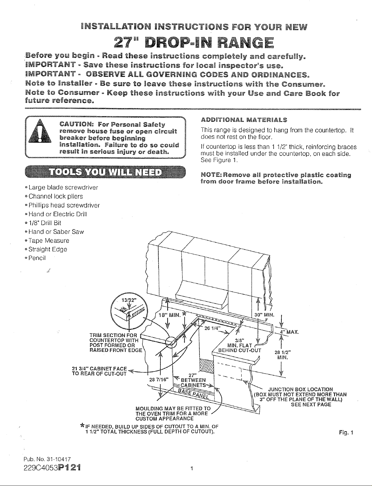
This range is designed to hang from the countertop. It
does not rest on the floor.
If countertop is less than 1 1/2" thick, reinforcing braces
must be installed under the countertop, on each side.
See Figure 1.
NOT_: Remove a_ protective p_ast_¢ coating
_rom doo_" _'rame be_'o_'e _nstaHat_on.
21 3/4" CABINET FACE
TO REAR OF CUT-OUr
Pub. No. 31-10417
229C4053Pt 21
TRIM SECTION FOR
COU
POST FORMED OR
RAISED FRONT EDGE
28 7/16"
MOULDING MAY BE FITTED TO
THE OVEN TRIM FOR A MORE
CUSTOM APPEARANCE
_IF NEEDED, BUILD UP SIDES OF CUTOUT TO A MIN. OF
1 1/2" TOTAL THICKNESS (FULL DEPTH OF CUTOUT).
30" MIN.
28 1/2"
MIN.
JUNCTION BOX LOCATION
BOX MUST NOT EXTEND MORE THAN
3" OFF THE PLANE OF THE WALL)
SEE NEXT PAGE
Fig. 1
Page 2
,'Be sure the oven is securely installed to a cabinet that
is firmly attached to the house structure. Weight on the
oven door could potentially cause the range to tip and
result in injury. Never allow anyone to climb, sit, stand,
or hang on the oven door.
,,A 30" minimum clearance is required between the top
of the cooking surface and the bottom of an
unprotected wood or metal cabinet.
,,Put the range near a work surface for convenience.
oThe cooktop should be easy to reach and lighted with
natural light during the day.
,,To reduce the risk of burns or fire by reaching over
heated surface units, cabinet storage space located
above the surface units should be avoided. If cabinet
storage space is to be provided, the risk can be
reduced by installing a range hood that projects
horizontally a minimum of 5" beyond the bottom of the
cabinets.
oSee Figure 1 for all rough-in and spacing dimensions.
These dimensions must be met for safe use of your
range.
oLocate a wiring junction box at the rear of the cutout.
The dimension from the top of the wiring junction box to
the countertop must be a minimum of 28 1/2". The box
must not extend more than 3" off the plane of the wall.
See Fig. 1_ The junction box must be located where it
will allow considerable slack in the range conduit, so
that the range can be pulled for servicing if necessary.
,, Make sure the wall coverings, countertops and
cabinets around the range can withstand temperatures
of up to 200°F generated by the oven, range or
cooktop.
WHEN HNSTALLiNG RANGE mNCOUNTERTOP
WHICH iS CUT OUT TO THE WALL
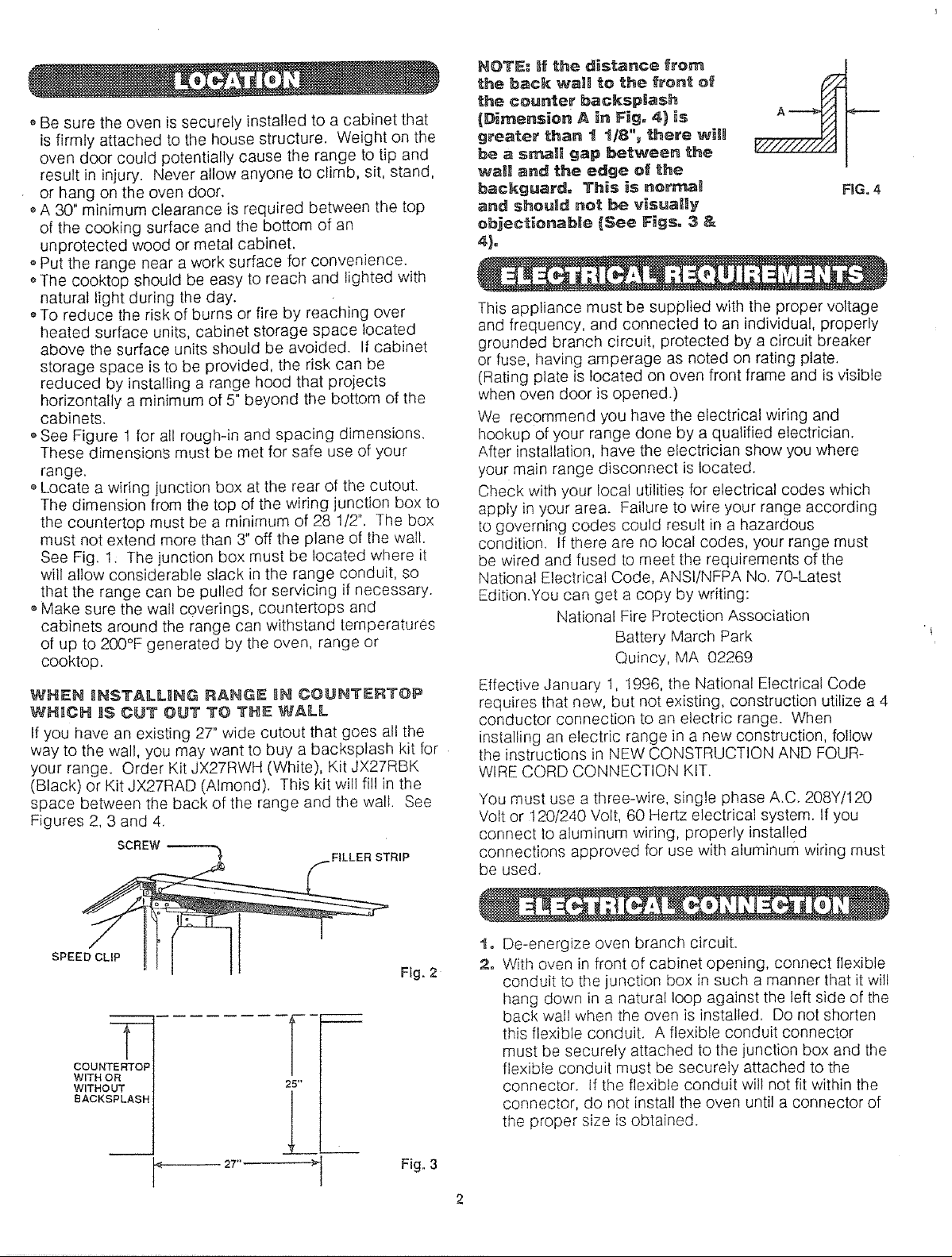
If you have an existing 27" wide cutout that goes all the
way to the wall, you may want to buy a backsplash kit for
your range. Order Kit JX27RWH (White), Kit JX27RBK
(Black) or Kit JX27RAD (Almond). This kit will fil! in the
space between the back of the range and the wall. See
Figures 2, 3 and 4.
SCREW.--------.,
FILLER STRIP
NOTE: lit the distance from
the back walll to the front of
the counter backsplash
(D_mension A in Fig= 4) _s
greater than I 1/8"_ there wiin
be a small gap between the
wail and the edge of the
backguard. This is norn'_
and should not I:_ visually
objecf:ionabie {See F_gs. 3 &
FIGo 4
4}o
This appliance must be supplied with the proper voltage
and frequency, and connected to an individual, properly
grounded branch circuit, protected by a circuit breaker
or fuse, having amperage as noted on rating plate.
(Rating plate is located on oven front frame and is visible
when oven door is opened.)
We recommend you have the electrical wiring and
hookup of yOUr range done by a qualified electrician.
After installation, have the electrician show you where
your main range disconnect is located.
Check with your local utilities for electrical codes which
apply in your area. Failure to wire your range according
to governing codes could result in a hazardous
condition. If there are no local codes, your range must
be wired and fused to meet the requirements of the
National Electrical Code, ANSI!NFPA No. 70-Latest
Edition.You can get a copy by writing:
National Fire Protection Association
Battery March Park
Quincy, MA 02269
Effective January 1, 1996, the National Electrical Code
requires that new, but not existing, construction utilize a 4
conductor connection to an electric range. When
installing an electric range in a new construction, follow
the instructions in NEW CONSTRUCTION AND FOUR-
WIRE CORD CONNECTION KIT.
You must use a three-wire, single phase A.C. 208Y/120
Volt or 120/240 Volt, 60 Hertz electrical system. If you
connect to aluminum wiring, properly installed
connections approved for use with aluminum wiring must
be used.
SPEE
COUNTER'FOP
WITH OR
WITHOUT
BACKSPLASH
2T'-------_
25"
L_
Fig. 2
Fig, 3
De-energize oven branch circuit.
2o
With oven in front of cabinet opening, connect flexible
conduit to the junction box in such a manner that it wilt
hang down in a natural loop against the left side of the
back wall when the oven is installed. Do not shorten
this flexible conduit. A flexible conduit connector
must be securely attached to the junction box and the
flexible conduit must be securely attached to the
connector. If the flexible conduit will not fit within the
connector, do not install the oven until a connector of
the proper size is obtained.
Page 3

Allnewconstruction,mobilehomesandinstallation,
wherelocalcodesdonotallowgroundingthrough
neutral,requireafour-conductorbranchcircuit.For
existingconstruction,athree-conductorbranchcircuit
connectionmaybeused.
NOTETO ELECTRICIAN: The three power
l]eads supplied w_th this appliance are UL
recognized for connection to _arger gauge
household w_ring, The insulation o_ these
three _eads _s rated at temperatures much
h_gher than the temperature rating of
househol_d w_ringo The current carrying
capacity o_ the conductor is governed by the
temperature rating ef the insulation around
the wire_ rather than the w_re gauge alone°
,,When installing in a new construction, or
oWhen installing range in a mobile home, or
When local codes do not permit grounding through
neutral:
1= Cut the neutral (white) lead from the crimp. Re-slrip
the neutral (white) lead to expose the proper length of
conductor.
2o Attach the appliance grounding lead (green or bare
copper) to the branch circuit grounding conductor
(green or bare) in accordance with local codes. If the
branch circuit grounding conductor is aluminum, see
"WARNIING" note.
3. Connect the range neutral (white) lead to the branch
circuit neutral (white or gray) in accordance with local
codes. If the branch circuit neutral conductor is
aluminum see "WARNIING"note.
4. Connect the range red lead to the branch circuit red
lead and the range black lead to the branch circuit
black lead in accordance with local codes. If the
residence red and black leads are aluminum
conductors, see '%VARNING" note.
Fig. 5
2. Grasp the door at each side and lift up and off the
hinges.
re_oved and h_nge arms are at
CAUTION: When the door _s
s'Lop position, do not bump or try
to move the hinge arms° The
hinges could snap back causing
an _njuPj 1o the hands or damage to the
porcelain on the _ront oI_the range, Cover
the hinge:_ with toweling or _nsert empty
towe_ roH.,_ behind the h_nges wh_e
working _n the oven area=
POS_T_OHI_NIG TH_ RANG_ IN OPEH_NG
:3. Raise lift-up cooktop and support it With cooktop support
rod (see Fg. 6).
4o Attach lower trim to front frame and side trim with screws
provided i_ the literature package (see Fig. 7).
5, [:)rill I/8" diameter pilot holes into counter[op using holes
in upper side panels. Attach range to countertop with
four scre_s provided in literature package (see Fig. 6).
When connecting to a 3-conductor branch circuit, if
local codes permit, connect the bare oven conductor
with the crimped neutral (white) lead to the branch
circuit neutral (white or gray in color), the oven red lead
to the branch circuit red lead and the oven black lead to
the branch circuit black lead in accordance with local
codes.
Fig. 8
Page 4

provides an opening for coo,ling air
_o enter the cabinet= Th_s _)pen_ng
CAUTION: The botto_ of _he "_ri_
should never be b_ocP_edo
Fig. 7
REPLACe: OV_=H DOOR
5. Hold the door over the hinges with the s}ots at the
bottom edge of the door lined up with the hinges.
The hinge arms must still be in the stop position.
6o Slide the door down onto the hinges as tar as it will
go and close the door (see Fig. 5 on previous page).
J
You may purchase a Backsplash Kit from yDur GE
dealer, Order kit JX27RWH (white), kit JXZTRBK (black)
or kit JX27RAD (almond), Follow installation instructions
in the kit.
NOTE: The backspEash k_t attache.,_ to the
counte_=
Pub. No. 31-10417
229C4053P121
Recycled Paper
Printed in LaFayette_ Georgia
 Loading...