

Page 1
“
‘
Gas
Range
Safe* Instrudons....................2-5
Anti-Tip
Deviw
.............................2, 3, 19,28
Operating Instructions,
Ttps
Aluminum Foil ............................5, 14, 16, 17
Features
............................................................7
Flooring/Leveling ...........................................6
@en.. . . . . . . . . . . . . . . . . . . . . . . . . . . . . . . . . . . . . . . . . . . . . . . . . . . . . . .
.
l&18
Baking . . . . . . . . . . . . . . . . . . . . . . . . . . . . . . . . . . . . . . . . . . . . . . . . .
.
13, 14
Broiling, Broiling
Guide...........,.........l7,
18
Oven Control . . . . . . . . . . . . . . . . . . . . . . . . . . . . . . . . . . . . . . . . . . . . .
.
10
Roasting,
Roast;ng
Guide................l5, 16
Shelves . . . . . . . . . . . . . . . . . . . . . . . . . . . . . . . . . . . . . . . . . . . . . . . .
.
11, 13
Sutiace
Cooking .........................................8, 9
Control Settings ..........................................8
Electric Ignition .......................................8, 9
Care and Cleaning
....................l
9-24
Broiler Pan and
Rack..........................................22
Burner
.mbW...........
. . . . . . . . . . . . . . . . . . . . . . . . . . . . .
.
19-21
Coomp ..........................................................2 1
Door
Removal
......................:........,...............23
@en'.~~orn.................................................22
~~Oj-lejD~~w6r
.
,, .,..
. . . . . . . . . . . . . . . . . . . . . . . . . . . . . . . . . . . . . . . . .
22
Problem Solver.
..............................34
Thermostat
Adjustment-
Do It
Yourself
. . . . . . . . . . . . . . . . . . . . . . . . . . . . . . . . . . . . . . . .
.
12
More questions
?...call
GEAnswer Cente~
80~626.2000
consumer Services ...................36
Appliance
Registration..................................2
Imponant Phone Numbers .......................36
Model and Serial Number Location ...........2
Warranw
......................,.................Back
Cover
Models:
JGAS02PN
JGAS02EN
JMS02PN
,,
. . .
Page 2
=LP
US
~LP
YOU
Read this book
carefdy.
~
you received a damaged
rarige...
It is intended to help you operate and maintain your
tiediately
contict the alder (or builder) that sold
new range properly.
you
the
range.
Keep it handy for answers to your questions.
Save time and money. Before you
If you don’t understmd something or need more help,
requ=t service...
write (include your phone number):
Consumer Affairs
Check the Problem Solver in
tie
GE Appliances
back of this book. It lists causes of
Appliance Park
minor operating problems that you
Louisville, KY 40225
cm
correct yourself.
@
@m’Mn
Write
dom
the model and serial numbers.
You’ll find the model and
senrd
numbers on two labels
on the range front frame near the broiler drawer.
These numbers are
dso
on the Consumer Product
Ownership Registration Card that came with your
range. Before sending in this card, please write these
numbers here:
Model Number
Setial
Number
Use these numbers in any correspondence or service
calls concerning your range.
a
4
A WAWNG
h
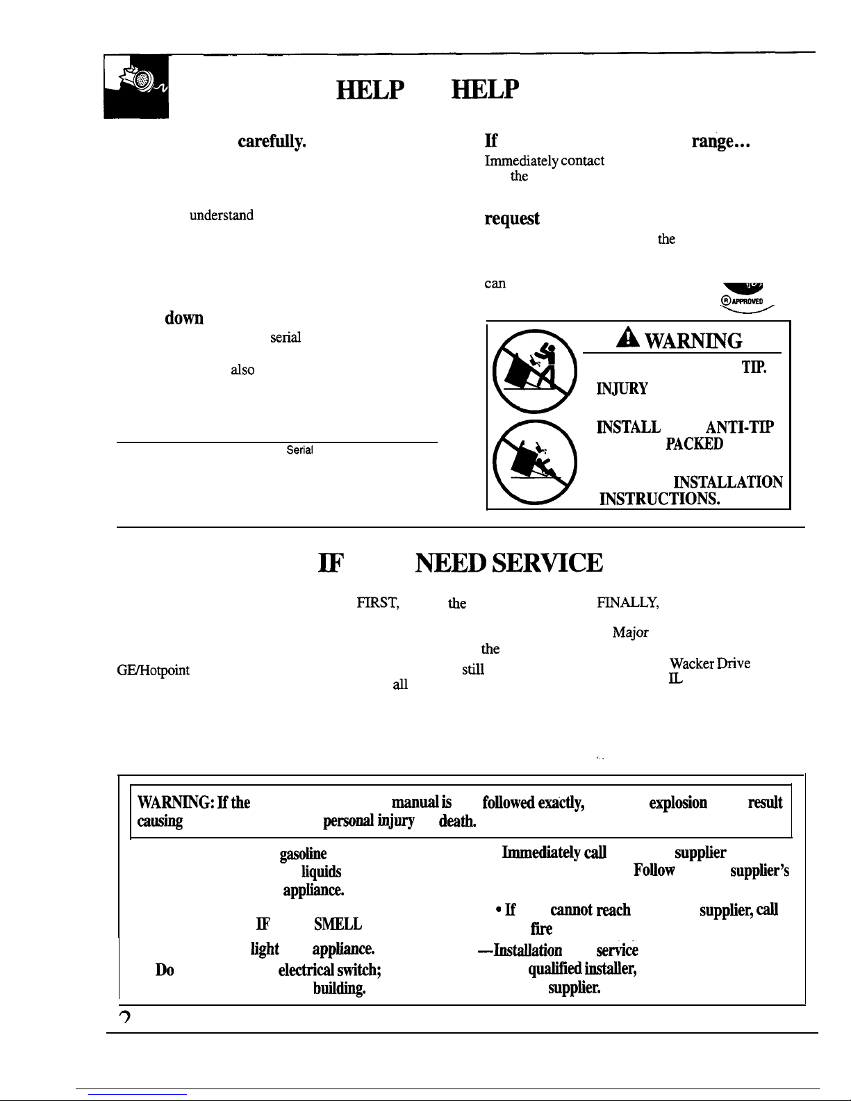
●
ALL RANGES CAN
TW.
●
INmRY
TO PERSONS
w
COULD RESULT.
@
●
~STALL
THE
ANTI-TW
b,
DEVICE
PAC~D
WITH
THE RANGE.
●
SEE THE
~STALLATION
~STRUCTIONS.
~
YOU
~ED
SERWCE
To obtain service, see the
Consumer Services page in the
back of this book.
To obtain replacement parts, contact
G~otpoint
Service Centers.
We’re proud of our service and
want you to be pleased. If for some
reason you are not happy with the
service you receive, here are three
steps to follow for further help.
HRST, contact
the
people who
serviced your appliance. Explain
why you are not pleased. In most
cases, this will solve
the
problem.
NEXT, if you are
sti~
not pleased,
write dl the details-including
your phone number—to:
Manager, Consumer Relations
GE Appliances
Appliance Park
Louisville, KY 40225
~ALLY,
if your problem is still
not resolved, write:
Major
Appliance Consumer
Action Panel
20 North
Wacker Wve
Chicago, ~ 60606
.., .
WAHG: Mthe
information in this
mand is
not
fotiowed emctiy,
a fire or
e~losion
may
At
musing
property damage,
persod tijury
or
dmth.
—Do
not store or use gasotie or other
●
-ediately d
your gas
suppher
from a
flammable vapors and
Mquids
in the vicinity
neighbor’s phone.
FOUOW
the gas
supptier’s
of this or any other
apptiance.
instructions.
—WHAT
TO DO ~ YOU
S~LL
GAS
c M
you
mot mch
your gas
supptier, ~
the fw department
●
Do not try to
tight
any
apptie.
—btiation
and
service
must be performed
●
Do
not touch any
el~trid swikh;
do not
by a
qtiled Mer,
service agency or
use any phone in your btiding.
the gas
supptier.
Page 3
WORTW
S~TY
NO~CE
●
The
Mornia
Safe
Brirddng
Water M
Tom
Enforcement Act
requires
the
Governor of
C~ornia to pubtishatist
of substances hownto
the
state to cause
canmr, birth
clef* or
other
reproductive harm, and requires businesses to warn
customers
ofpotenthd
exposure to
such
substanm.
●
Gas
apptim can muse
minor
exposw
to
four
of tiese substances,
namely beme,
carbon
monotide,
formaldehyde and
soog
caused
primdy by the incomplete combustion
of
nati
gas or
LP hels,
Properly
adjusted burners,
indicated
by
a bluish rather b a
yeflow flame,
m~
incomplete combustion.
&posm
to
thes6’subs~ces canbe
. “ “
@by vendng
with
an
open window or using a ventilation fan or hood.
~enYou &t Yom -e
●
Have
the Mer sbow
you
fie
location of
the
qe w
at-off
vdveti
how
toshutit off
Mnecessary.
●
Have yon -e Wed
and
pro~rly
grounded by a q-cd
Mer,
in
accordanm
with the
kstiation
ktructions. Any
adjustment
and service
shotid
be
perfomed o~y
by
q-cd
gas range
instiers
or service *hrdcians.
●
Phg
your
~~
into a
l~volt ~unded
outie$ dy. Do
not remove
tbe
round
grountig
prong
bmthe
plug.
Ein doubt
about the
grounding of the
home electrid system it is yom
personal
respomibfity and ~tigation
to have
m
ungrounded
outiet repl*
with a properly
grounm-prong outiet in
accordance
witb
the
Nstiti MectridCode. h C-
the
apphana
must
be
electri@y @unded
in
accordance with
the Ctian M=trical.
Code.
Do
not use
an extension
cord
with this
app~an%.
Q Do not
zttempt
to
_
or
rephee
ay
partofyourrange
urdessittispecifi*y
recommended &
M
@da M other
servicing
shodd
be referred to a
q~ed tecMcian.
Q -te _
out of Mtien
tic pati
and
out of
-
btiow
to
prevat pnot
OU*
(onstanding@ot rnod~)
and poor air
*tiom
Q
Be
m
W
pa-
mated*
are removed
from
the range
before operating it
to~vent * or
smoke damage
shotid
the packing material
ignite.
●
Be sure
your range is
co-y
adjusted by a
q-cd
servim t-cian
or ●
~for
the
type of ~
(uati
or.W)thatis to
be
used.
Your range can be converted for use with either
type of gas. Seethe
btiation kstructions.
W-G:
These adjustments must be made by
a ~dified
serviee tihnician
in accordance with
the
manufactir’s
instructions and W codes and
requirements of
the
authority
having
jurisdiction.
Failure
tofo~ow
these instructions
codd resdt in
setious
injury or property damage. The
q~ed
agency performing this work assumes
responsibtity
for
the
conversion
*After prolonged
w ofa _
~
kr
~peram
may
wtit
and
many floor
#V~ti& @
not
tihd
~ Md of
m
Never
@til b
range
over
vinyl
tie
or holerun
that
cannot
withstand such type of use, Never
instil it -y
over
interior
kitchen carpeting.
WAmNG–M_
m
tipand~~atit
~
prev@nt8WidenM@pingof
the
~% ~h~
approved
~ti-~q
device
to tie
wW. (SW kstiation
@
hstructions.)
To
chd
if the device
is
in-
and
engaged
properly,
care~y
tip
tie range
forward, The
Anti-Tip device
shotid engage
and
@
prevent
therauge from
tipping
over. Hyoupdl
the
range out from the wd for any
reaso~
make
sw
the Anti-Tip device is engaged
when
you push the
range
back
agtist
the
wW.
Hit
is
not
there is a possible risk of the range
tipping over if you
or
a
c~d stan~
sit or lean on
an open
door.
3
Page 4
●
Do not
leave
Mdren #one or
unattended
where a range is
hot or
in operatia
They
cordd
be seriously burned,
●
Do
not
Uow
anyone to ebb, stand or hang on
the
door,
brotierdrawer
or range
top.
They
cordd
damage the range and even tip it over,
causing severe
perso~ ~~.
●
Ut
burner
grab
and
other surfam cool
before
tonctig
them or leaving them where
Mdren
can reaeh
them.
●
Never wear loose
fitig
or
hanging
garments
whtie wing
the
apptian%
Be careti
when
reaching for items
stored
in
Mbinets
over
the
cooktop. H_le
rnaterhd
codd be ignited if
brought
in contact witi
tie or
hot oven
sti~~s
and
may
cause severe
burns.
●
For
your safety, never use
your apphce
for
we
or heating the
room.
e
e Do not m
water on grease
m.
Never pickup
ating
pan. Turn off
burner, then
smotberfbuning
p~. by
wvering
pan
mmpletely
with
wefl-fitting HA
cookie sheet or fiat tray.
Haming -e
outside a
pan
can
be put out by covering with baking
soda
or, if
avdable, a muki-purpose
dry chemical or
foam-type
fix
extinguisher.
* Do
not store
tible
rnaterkds
in an
oven>
a range
brotier
drawer or near a
cooktop.
s Do
not
store
or
use combmtihle materkds$
gasotineor
other
fhunmablevapors
and
tiquids
in the
victity of
this or any other
app~anee.
s Do
not let cooking grease ar other
tible
materkds ac-tite h or
near the range.
●
men coo- pork$
follow thedirections
exacdy
and always
cook
the
meat
to an internal
temper- of
at
least 170°F.
This assures M4
k
the
remote
possibfity
that trichina may be pment
in
the meat, it
til
be
ki~ed
and the meat W be
safe to eat
Stiace CMQ
●
Always w the L~ position (on
electic
ignition
rnodek)
or the ~ position (on standing
pflot modek)
when igniting top burners and
make sw the
burnem
have ignited.
●
Never leave tiace
burners unattended at
Mgh tie
settings.
Boilovercauses
smoking
and greasy
spi~overs
that may catch on
fie.
●
Adjust
the top
burner
flame* so it does not
e~nd
beyond the edge of the cookware.
Excessive flame is
Wardous.
o
Use O* dry pot
holde-moist
or damp potholders on hot surfaces
may
resuk
in burns from steam. Do
not
let
pot
holders come
near open
flames when
~g
cookware. Do not use a towel orotherb@
cloth in place of a
pot
holder.
●
To
~
the
possibtity
of burns,
ignition
of
flmable
materials, and
$pWge,
turn
cookware hmdes toward the side or back of the
range without extending over adjacent burners.
●
Always b the
stiaee burner
to 0~ before
removing the cookware.
“ CareMy wati foods
being fried at a high
flame setting.
●
Never
blti
the
venb (tir
openings) of the
rangk
They provide
the h
Met
and
outiet
that
are necessary for
the mge to operate
properly
with
corrwt
combustion. W openings are located
at.the
rear of the
cooktop,
at
tie
top and
bottom
of
the
oven door,
and
at the bottom of the range
mder the
broiler drawer.
●
~
not
use a wok on
modeh
with
-ed
burners
Uthe
wok
has a
round
mettd
ring that is
phced
over the
burner
grate to
snpport
the wok.
This
ring
acts as a heat
#p,
which
may
damage the
burner grate
and buraer
head. Aso, it may cause
tie
burner to work
@properly.
This may cause a
carbon
monofide level
above that
Wowed
by
current standards,
resdtig
in a
heakh -.
4
Page 5
● Foods for-
shotid
be as dry as
possible
Frost on
tiomn
foods or moisture on fresh foods
can
cause
hot fat to bubble up and
over
sides of
the
pan.
●
Use least possible
am-t
of fat
for
effective
shtiow or deepfat =.
Filhg
the
pan too
W
of fat
can cause spflovers
when food is added.
●
Ka
cornbtiation
of & or
fa~ ~
be used
k f-,
stir
together
before
heating or as fats
melt
#owly.
●
Use a deep fat thermometer whenever
possible
to
prevent
overheating
tit beyoudthe
Smotig point.
*Use
proper
~
&Avoidpms
that are
uustable
or
dy tip Sel@ mkware hatig U
bottoms &
6nough
to properly contain
food
and
avoid
botiovers
and
sptiovers
and ~e
mou@ to
cover burner grate. ~s W both save cleaning
time nd prevent
=ous accmmdatiom aff~
since heavy
s-g
or
spMovers
left on range
can ignite. Use pans with
han~es
that can be
easfly
wm
and remain cool,
●
men X -
cookware,
make
snre
it is
designed for top-of-range cooking.
. Keep fl
p~es away
from top
buraers.
*
M
not leave
pktic i-
on the
cooktop
they may
melt if left too close to the
vent,
●
M
not bve ~
items
@n the
eooktop.
me
hot
air from the
vent may
ignite
tible
items
and
til inmepresswin closed
containers,
which
may
canse
them to
burs~
●
To avoid
the possibtity
ofa
bum akways
be
certain that
the controb
for ~ bmers are at
the OFF petition and
W
grates are-before
attemp~ to
remove
them.
amen -
foods are
mder
the hood, turn
the fan
off. me f- ifoperatig, may
spread
the
ti~
c W mge &
located near a
fidow,
do not hang
long curtains that
codd
blow over the top burners
and create afire
h-.
*men
a
ptiot gw
out (on
s~ding
@ot
models),
you til detwt
a faint odor of gas as your
sigmd
toretight the pfi~t. men
refighting the
ptio~
make snre
burner controk
are in
the Om
position,
and
fo~ow
instructions in this book to
re~ght.
●
Hyou smM
gas,
and you have
hdy made
sure
pdots me tit (on staatig pilot
models),
turn off the gas to W
mge
and
eti
a qualified
service
t~hnician.
Never
use
an open
flame
to
~ate
a leak.
cl-
Yow -e
●
Clean ody parts M k W Use =d
~re Nde.
~
Keep_
d-and k of aeeumrdations
of
-
or
spWoVem
which my @k
* W mti
when
you
clean the
cooktop
because
5
Page 6
Your range,
tike
many other household items,
The range should be
instiled
on a l/4-inch thick
is hwvy and can settle into soft floor coverings
sheet of plywood (or similar
materird)
as
fo~ows:
such as cushioned vinyl or
arpeting.
men
the floor covering ends at the front of the
men
moving the range on this type of flooring, use
range, the area that the range
wi~ rest on should be
care, and it is recommended that these simple
built up with plywood to the same level or higher than
instructions be followed.
the floor covering. This
wfll tiow
the range to be
moved for cleaning or servicing.
Leveling legs are located on each corner of the base
of the range. Your range must be level in order to
produce proper cooking and baking results. Merit is
in its
find
location, place a level
horizontily
on any
oven shelf and check the levelness front to back and
side to side. Level the
rmge
by adjusting the leveling
legs or by placing shims under the comers as needed.
One of the rear leveling legs will engage the
hti-Tip
device (allow for some side to side adjustment).
Mlow a minimum clearance of 1/8 inch between the
range and the
levehng
leg that is to be
instrdled
into
the
hti-Tip
device.
6
Page 7
Y
I
+
Shnding
Pilot Models
JGAS02PN
JLAS02PN
\
Electtic Ignition Model
JGAS02EN
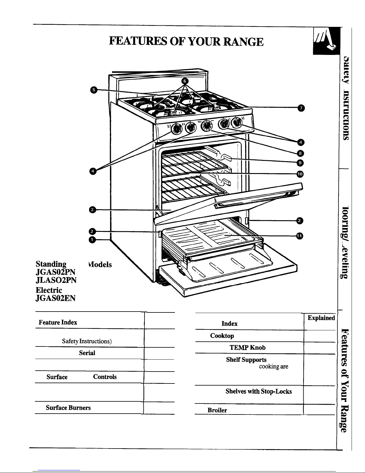
Fwture hdex
1 Anti-Tip Device
(see
Safe~ hstructions)
2 Model and
Serbd Number
3 Removable Oven Bottom
4
Sutiace Burner Controk
5 Oven Vent
(located in center of rear of range)
6 Sutiace Bumem and Gratin
Explained
on page
3,5
2
16
7
9
Feature
hdex
7 Cooktop
8 OVEN
TEMP
Mob
9 Oven
SheHSuppoti
Shelf positions for
coobg are
suggested in the Baking, Roasting
and Broiling pages.
10 Oven
Shelv~ tith Stop-bcks
14, 15, 17
11 Brotier Pan and Rack
Expltied
on page
14
9
9
9, 15, 17
13, 15, 17
7
Page 8
SMACE
COO~G
Lighting Instructions for Electric Ignition Models
JGAS02EN
The surface burners on some models me lighted by
electric ignition, eliminating the need for standing pilot
The electrode of the spark igniter is exposed.
lights witi
constandv
burning
flames.
men
one burner is turned to
LITE, W tie
burners
-
In me of a power failure, you can light the surface
spark. Do not attempt to disassemble or clean
burners on your range with a match. Hold a
hghted
around any burner while another burner is on.
match to the burner, then turn the knob to the
L~
An electric shock may result, which could cause
msition. Use extreme mution when
ti~hti
burners
you to knock over hot cookware.
I
I
hs
way.
--
Surface burners in use when an electrical power failure
occurs will continue to operate normally.
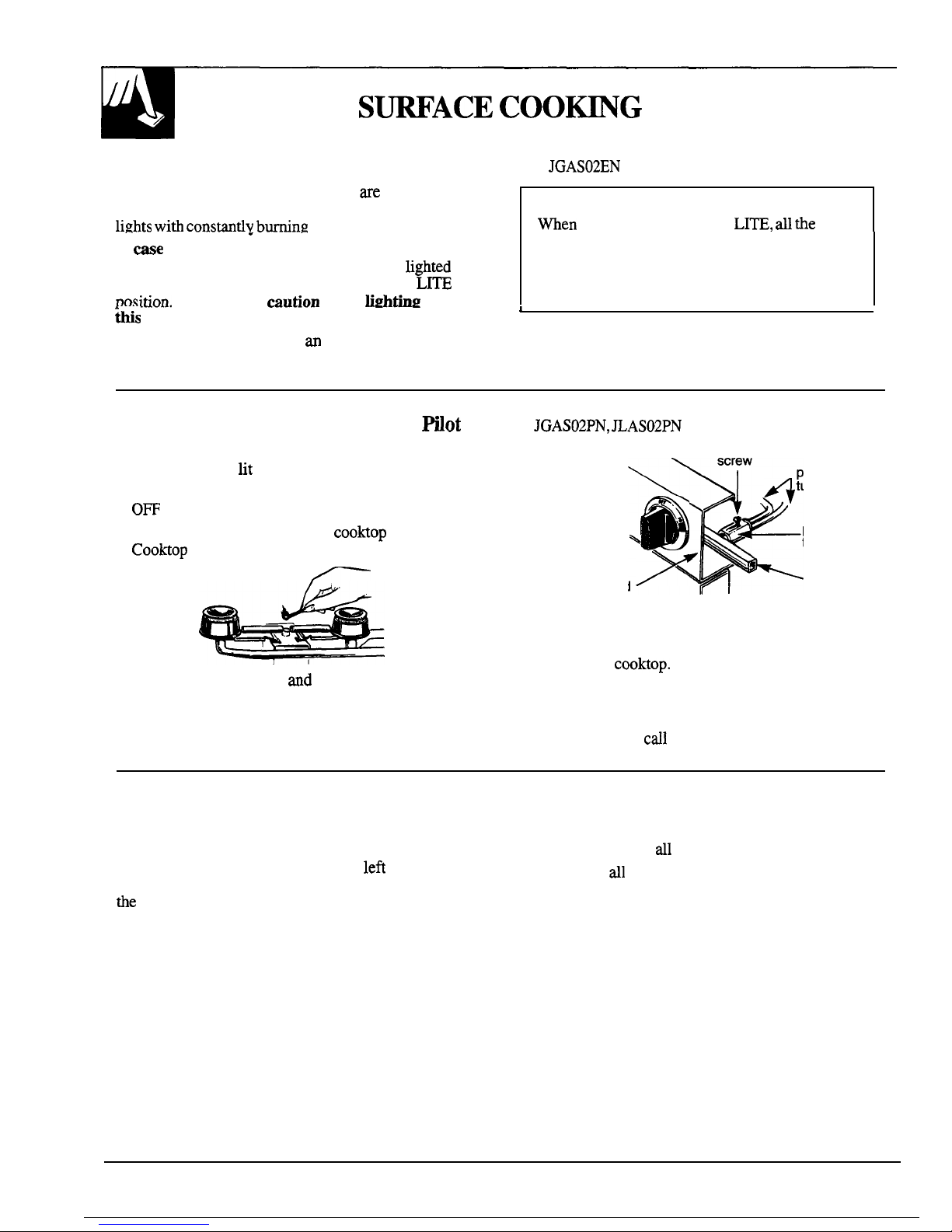
Lighting Instructions for Standing
mot
Models
JGAS02PN, JLAS02PN
The surface burners on these ranges have standing
pilots that must be
tit
initially. To light them:
1. Be sure surface burner control knobs are in the
0~
position.
-
2. Remove the grates and lift the
cooktop
up (see the
Cooktop
section).
3. Locate the 2 pilot ports
ad
light each of them with
a match.
pilot
adjustment
%
screw
&
4
pilot
tubes
2
\
pilot
filter
manifold
7
manifold
panel
pipe
4.
If the pilots need adjusting, turn the adjusting screw
located on the pilot filter.
5. Lower the
cooktop.
Your surface burners are now
ready for use.
6. Observe lighted burners. Compare the flames to
pictures in the Problem Solver. If any flame is
unsatisfactory,
crdl
for service.
Surface Burner Controls
Before Lighting a Burner
The knobs that turn the surface burners on and off are
●
If drip pans are supplied with your range, they
located on the control panel on the front of the range.
should be used at
dl
times.
The two knobs on the left control the
lefi
front and
left rear burners. The two knobs on the right control
●
Make sure dl the grates on the range are in place
the
right front and right rear burners.
before using any burner.
8
Page 9
To Light a Surface Burner
After Lighting a Burner
Electric Ignition Modeh:
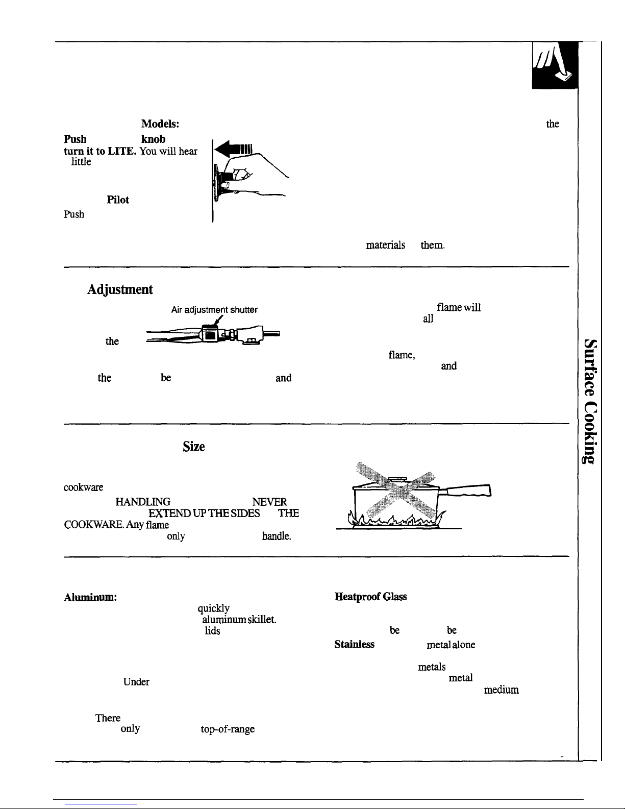
~h
the control
hob
in and
tumittoLITE.Youwillhem
~1111
a litde “clicking” noise—the
sound of the electric spark
igniting the burner.
Standing Hlot Model:
Wsh control knob in and turn
P
it to HI position. The burner
should light within a few seconds.
●
After the burner ignites, turn the knob to adjust
tie
flame size.
●
Check to be sure the burner you turned on is the one
you want to use.
●
Do not operate a burner for an extended period of
time without cookware on the grate. The finish
on the grate may chip without cookware to absorb
the heat.
●
Be sure the burners and grates are cool before you
place your hand, a pot holder, cleaning cloths or
other
matends
on
them.
Air
Adjw@ent
An air adjustment
shutter for each
surface burner
regulates
the
flow
of air to the flame.
When the right amount of air flows into the
burner,
the
flame will be steady, relatively quiet
and
have approximately 3/4-inch sharp blue cones. This is
usually the case with factory preset shutter settings.
With too much air, the
flame will
be unsteady,
possibly won’t burn
rdl
the way around, and will be
noisy, sounding like a blowtorch.
With not enough air, you won’t see any sharp blue
cones in the
flame,
you may see yellow tips and soot
may accumulate on pots
and
pans.
To adjust the flow of air to the burners, rotate the
shutters to allow more or less air into the burner tubes
as needed.
How to Select Name Sbe
Watch the flame, not the knob, as you reduce heat.
The flame size on a gas burner should match the
cookw~e you are using.
FOR SAFE
WL~G
OF COOKWARE
~WR
LET THE FLAME
EKTE~ W ~ S~ES
OF
~
COOKW~. Any flame
larger than the bottom of the
cookware is wasted and
ordy
serves to heat the
hande.
Top of Range Cookware
Almnin
um: Medium-weight cookware is
recommended because it heats
quictiy
and evenly.
Most foods brown evenly in an
durrdnum
stiet.
Use saucepans with tight-fitting
tids
when cooking
with minimum amounts of water.
Cast-iron: If heated slowly, most skillets will give
satisfactory results.
Enamelware:
Un&r
some conditions, the enamel
of some cookware may melt. Follow cookware
manufacturer’s recommendations for cooking methods.
Glass:
There
are 2 types of glass cookware-those
for oven use
ody
and those for top-of-rmge cooking
(saucepans, coffee and teapots). Glass conducts heat
very slowly.
Hwtproof Gks
Ceramic: Can be used for either
surface or oven cooking. It conducts heat very slowly
and cools very slowly. Check cookware manufacturer’s
directions to
be
sure it can be used on gas ranges.
Stahdess
Steel: This
meti done
has poor heating
properties and is usually combined with copper,
aluminum or other
metis
for improved heat
distribution. Combination
meti
skillets usually work
satisfactorily if they are used with
medium
heat as the
manufacturer recommends.
9
Page 10
Before Using Your Oven
Be sure you understand how to set the controls properly. Practice removing
and replacing the shelves while the oven is cool. Read the information and
tips on the following pages. Keep this book handy where you can refer to it,
especially during the
fwst
weeks of using your new range.
Lighting Instructions for Electric Ignition Model
JGAS02EN
The oven burner on ti range is tighted by electric ignition.
To
tight
the burner, turn the OVEN TEMP knob to the desired
temperature. The burner should
fight
within 30-90 seconds. After the oven
reaches the selected temperature the oven burner cycles on and off to
maintain the selected temperature.
Power Outige
A burner in use
when an
electricrd
power failure
occurs
wdl
continue to operate normally. Your oven
may be used during an electrical power
outige by
carefully following the steps below:
To tight the oven ptiot during an
electrid
power outage:
1. Be sure the OVEN TEMP knob is in the
OFF position.
2. Open both the oven and broiler doors and wait 5
minutes to allow any pilot gas to dissipate.
3. Unplug the range from the
wdl outiet,
turn off the
circuit breaker, or remove the fuse to avoid
accidenti
ignition of the oven if electrical power is
restored
wtie
you are lighting the
pflot.
4. Remove the broiler pan.
5. Locate the oven pilot assembly by looking into the
broiler opening. The pilot is at the back of the
broiler compartment, on the right side of the burner.
NOTE: The oven must beat room temperature
before you should attempt to light the oven pilot
manually.
6. Turn the OVEN TEMP knob to the desired
temperature setting.
7. Light the pilot with a match and withdraw your arm
immediately because the oven burner may light in
as
litie
as 20 seconds.
8. Replace the broiler pan and close the oven and
broiler doors.
NOTE: It is necessary to light the pilot manually
each time the oven is used during a power outage.
Lighting
htructions
for
Stiding mot
Models
JGAS02PN, JLAS02PN
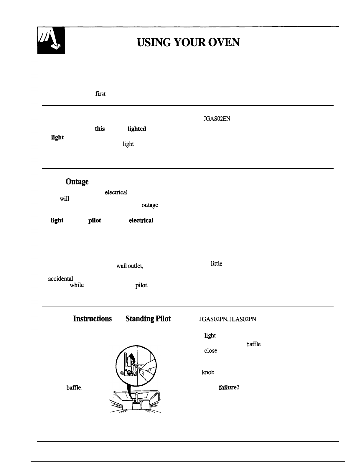
These ranges have standing oven pilots that must be
4. Using a long match or match holder, reach in and
lit initially. tight
the oven pilot.
To light the oven pilot:
1. Be sure the OVEN
TEMP knob is in the
OFF position.
2. Remove the oven
bottom and the
burner
btie.
See the Care and
Cleaning section.
3. Find the oven pilot
port at the back of
the oven.
5. Place the burner
btie
and the oven bottom and
cIose
the door. Your oven and broiler are now ready
for use.
● To light the oven burner, turn the OVEN TEMP
bob
to the desired temperature. The burner should
light within 60 seconds.
●
Power
faflure?
An electrical power failure will not
affect the standing oven pilot.
10
Page 11
Oven Control
Your oven is controlled by an
OWN TE~
knob.
After the oven reaches the selected temperature, the
It will
norrndly take 30-90 seconds before the flame
oven burner
cycles+ff
completely, then on with a
comes on.
full flame-to maintain the selected temperature.
Air
Adjw@ent
An air adjustment
shutter for the
oven burner
regulates the flow
of
air
to the flame.
You’ll find the
shutter against the
back
wdl
behind
the broiler drawer.
To reach it remove
&
/
.,’
—
,.’.-
,..
ti
. .
.
Loosen
/
‘+
Air
adjustment
shutter
the oven bottom (see the Care and Cleaning section)
and the burner
btie.
To
adjust the flow of tir,
loosen the
Philhps
head
screw and rotate the shutter to allow more or less air
into the burner tube as needed.
men
the tight amount of Ar flows
kto
the
burner, the flame
should be steady, with
approximately 1/2 inch blue cones, and should not
extend out over the
btie
edges.
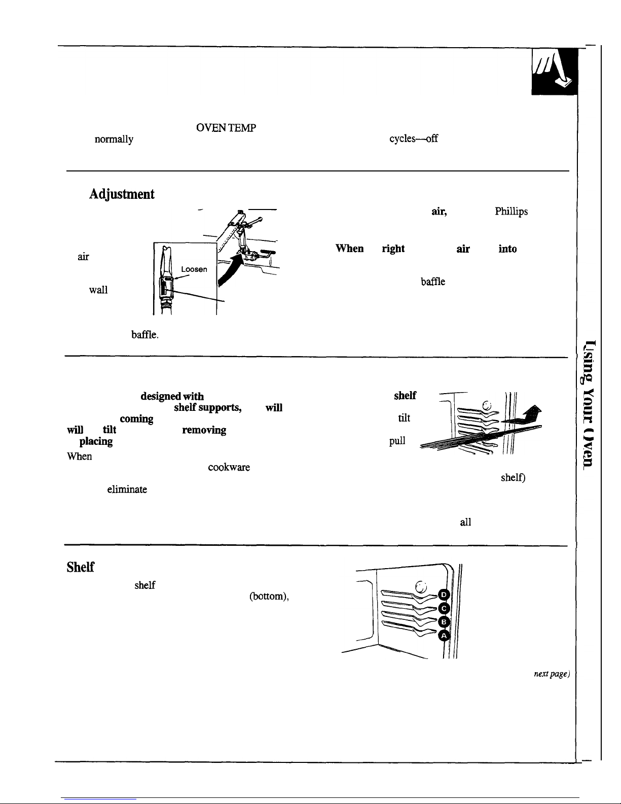
Oven Shelves
The shelves are
des~ed tith
stop-lock so when
placed correctly on the
sheM suppo~,
they
till
stop before
co~ng
completely out of the oven and
fi
not
tit
when you are
remotig
food from them
or
plachg
food on them.
men
placing cookware on a shelf, pull the shelf out
to the “stop” position. Place the
cookwme on the
shelf, then slide the shelf back into the oven.
This will
elimimte reaching into the hot oven.
To remove a sheti
from the oven, pull
it toward you,
tit
the front end
upward and
pull
the shelf out.
*
6
-1
1-
Iill
To
replace,
place the shelf on the shelf support with
the top-locks (curved extension of the
shel~ facing up
and toward the rear of the oven. Tilt up the front and
push the shelf toward the back of the oven until it
goes past “stop” on the oven wall. Then lower the
front of the shelf and push it
dl
the way back.
SheM
Positions
The oven has 4 she~ supports for normal baking and
roasting identified in this illustration as A
~ottom),
B, C, D (top).
Shelf positions for cooking are suggested on the
Baking, Broiling and Roasting pages.
(continued
ne~page)
11
Page 12

USmG
YOUR
O~N
(continued)
Oven Vents
The
oven is vented
tiough
duct openings at the rear
●
Handles of pots
and
pans on the cooktop may
of the cooktop. See
the
Features section. Do not block
become hot if left too close to the vent.
the
opening when cooking in the oven—it is
●
Meti
items
til
become very hot if they are left
important that the flow of hot air from the oven and
fresh
air
to the oven burner be uninterrupted.
on the cooktop and
codd ause
burns.
●
Do not leave any items on the cooktop. The
hot air
●
The vent openings and
n-rby
surfaces may
become hot during baking and
brofing.
from the vent may ignite flammable items and will
Do not touch them.
increase pressure in closed containers, which may
cause them to burst.
● Do not leave plastic items on the
cooktop
they may meit if left too close to the vent.
Do Zt
Yourse~—Adjmt
the Oven
Themosbt
ffyou
don’t think the oven is heating at the right
temperature when you are baking or roasting, you
m
reset the thermostat
yourseM.
When cooking food for the f~st time in your new
oven, use time given on recipes as a guide. Oven
thermostats, over a period of years, may “drift” from
the factory setting
and
the differences in timing
between an old and a new oven of 5 to 10 minutes are
not unusual. Your oven has been set
correctiy
at the
factory and is more likely to be accurate than the oven
which it replaced.
We do not recommend the use of inexpensive
thermometers,
such as those found in the grocery
store, to check the temperature setting of your new
oven. These thermometers can vary by
2M0
degrees.
To
decide how much to change
the
temperature,
set the oven temperature
25°F.
higher or lower than
the temperature in your recipe, then bake. The results
of this “test” should give you an idea of how much the
temperature should be changed.
@
Note
~sition
of Winter
before adjustment.
~fl-~ %4
@
●
ao
L
P&@’
,
to
marks
~\
Loosen only the locking screws.
Note to which
mmk
the pointer is pointing.
To make an adjustment
carefully loosen
(approximately one turn), but do not completely
remove the two screws that hold the
skin to the knob.
Hold the knob blade in one hand and the outer
skirt
in
the other hand.
To raise the oven temperature,
move the pointer in
the direction of the arrow for
MSE.
To
lower the
temperature,
move the pointer in the direction of
arrow for LOWER. Each mark
WW
change the oven
temperature approximately
25°F.
We suggest that you
make
tie
adjustment one mark
from the original setting and check oven performance
before making any
additiond adjustments.
After the adjustment is made,
press skirt and knob
together and
retighten
screws so they are snug, but be
careful not to
overtighten. Re-instil
knob on range
and check performance.
NO~: -ran
adjustment has been made, the OFF
and
BROL
positions
wi~
not
tie
up with the indicator
mark on the control panel as they previously did. This
condition is normal and
wi~
not create a problem.
Page 13

How to Set Your Range For Bating
To avoid possible
bum,
place the shelves in the
2. Check the food for doneness at the minimum time
correct position before you turn on the oven.
on the recipe. Cook longer if necessary. Turn the
1.
Close the oven door. Then turn the OVEN
OVEN
~MP
knob to OFF and remove the food.
~MP
knob to the desired temperature.
For best baking results, follow these suggestions:
Oven Shelves
Arrange
the
oven
shelf or shelves in
the desired locations
while the oven is
cool. The correct
shelf position
depends on the kind
of food and the
browning desired.
As a general rule,
]
Type of Food
]
SheEPositio”
Angel food cake
A
Biscuits or muffins
B or C
Cooties or cu~akes
B or C
Brownies B or C
Layer cakes
B or C
place-most foods in the
tiddle
of the oven, on either
the shelf position B or C. See the chart for suggested
Bundt
or pound cakes
A or B
shelf positions.
Pies or pie shells
B or C
Frozen pies
A (on cookie sheet)
I
Casseroles
I BorC
Preheating
Reheat
the oven if the recipe
cds
for it. Preheat
Preheating is necessary for good results when baking
means bringing the oven up to the specified
cakes, cookies, pastry and breads. For most casseroles
temperature before putting in the food. To preheat,
and
roasts, preheating is not necessary. For ovens
set the oven at the correct temperature-selecting a
without a preheat indicator light or tone, preheat
higher temperature does not shorten the preheat time.
10 minutes. After the oven is preheated place the food
in the oven as
quic~y
as possible to prevent heat
from escaping.
BaKng
Pans
Use the proper baking pan. The type of
ftish
on the
pan determines the amount of browning that
wfll
occur.
●
Dark, rough or dull pans absorb heat resulting in a
browner, crisper crust. Use this type for pies.
●
Shiny, bright
rmd
smooth pans reflect heat, resulting
in a lighter, more delicate browning. Cakes and
cookies require this type of pm.
“
Glass baking dishes
dso
absorb heat.
men
baking
in glass baking dishes, lower the temperature by
25°F.
and use the recommended cooking time in
the recipe. This is not necessary when baking pies
or casseroles.
Pan
Placement
For even cooking
and
proper browning, there must be
enough room for air circulation in the oven. Baking
results will be better if baking pans
are
centered as
much
as
possible ramer than being placed to the front
or to the back of
the
oven.
Pans
shotid
not touch each other or
tie
walls of the
oven. Allow
1
to 1X inch space between pans as well
as from the back of the oven, the door and the sides. If
you use 2 shelves, stagger the pans so 1 is not
direcdy
above the other.
(continued
mxtpage)
13
-
..- .—
——
Page 14

BA~G
(continued)
Bahg Guides
men
using prepared baking mixes, follow package recipe or instructions
for the best baking results.
Cooties
men bting
cookies, flat cookie sheets (without
sides) produce better-looking cookies. Cookies
b~ed
in a jelly roll pan (short sides
rdl
around) may have
darker edges and
pde
or light browning may occur.
Do not use a cookie sheet so large that it touches the
walls or the door of the oven. Never entirely cover a
shelf with a large cookie sheet.
For best results, use
ody
1 cookie sheet in the oven
at a time.
Cakes
For best results, bake pies in dark, rough or dull pans
men
baking cakes, warped or bent pans will cause
to produce a browner, crisper crust. Frozen pies in foil
uneven baking results and poorly shaped products.
pans should be placed on an aluminum cookie sheet
A cake baked in a pan larger than the recipe
for baking since the shiny foil pan reflects heat away recommends will usually be crisper, thinner and drier
from the pie crust; the cookie sheet helps
retin
it. than it should be. H baked in a pan smaller than
recommended, it maybe undercooked and batter may
oveflow.
Check the recipe to make sure the pan size
used is the one recommended.
Altinu
Fofl
Never entirely cover a shelf with durninum foil.
This will disturb the heat circulation and result in poor
baking. A smaller sheet of foil maybe used to catch a
spillover
by placing it on a lower shelf several inches
below the food.
Don’t Peek
Set the timer for the estimated cooking time and do
DO NOT open the door to check until the
not open the door to look at your food. Most recipes
minimum time. Opening the oven door frequently
provide minimum and maximum baking times such
during
coo~ng
allows heat to escape and makes
as “bake 30-40 minutes.”
baking times longer. Your baking results may
dso
be affected.
14
——._..—.
Page 15

Roasting is cooking by dry heat. Tender meat or poultry can be roasted
uncovered in your oven. Roasting temperatures, which should be low and
steady, keep spattering to a minimum.
Roasting is
redy
a baking procedure used for meats. Roasting is easy;
just follow these directions:
1.
Place the shelf in the A or B position.
No preheating is necessary.
2. Check the weight
of the meat. Place
it, fat side up, (or
for poultry,
breast-
side-up) on the
roasting rack in a
shallow
pan.
The
melting
Fat
will baste the meat. Select a pan m
close to the size of the meat as possible. (The
broiler pan with rack is a good
pan
for this.) Line
the broiler pan with
rduminum
foil when using the
pan for marinating, cooking
witi
fruits, cooking
heavily cured meats, or basting food during
cooking. Avoid spilling these materials inside the
oven or inside the oven door.
3. Turn the OVEN
TEMP
knob to the desired setting.
4. After roasting is complete, turn the OVEN
TE~
knob to OFF and then remove the food from
the oven.
Most meats continue to cook
stightiy
while standing,
after being removed
horn the oven. Standing time
recommended for roasts is 10 to 20 minutes. This
allows roasts to
fm
up and makes them easier to
carve.
ktemd
temperature will rise about 5° to
10°F.
To compensate for temperature increase, if desired,
remove the roast from the oven sooner (at 5° to
10°F.
less than the temperature in the Roasting Guide).
NOTE: Remember that the food
wfl
continue
to cook in a hot oven and therefore should be
removed when the desired
intemd
temperature has
been reached.
Frozen
Romk
Frozen roasts of beef, pork, lamb, etc. can be started
Thaw most frozen poultry before roasting to ensure
without thawing, but allow 10 to 25 minutes per
even doneness. Some commercial frozen poultry can
pound
additiond time (10 minutes per pound for
be cooked successfully without
tiawing. Follow the
roasts under 5 pounds, more time for larger roasts).
directions given on the package label.
(continued
nat
page)
15
Page 16

ROASTmG
(continued)
Questions and Answers
Q.
Is it necessary to check for donenws with a
Q.
h
I need to preheat my oven
wch
time I cook
meat thermometer?
a roast or
potitry?
A.
Checking the finished
intemd
temperature at the
A.
It is
unnecessary to preheat your oven.
completion of cooking time is recommended.
Temperatures are shown in Roasting Guide. For
Q.
men
buying a roast, are there any special tips
that
wodd
help me cook it more
everdy?
roasts over 8 lbs., check with thermometer at
hdf-
hour interv~s after
hdf
the time has passed.
A. Yes. Buy a roast as even in thickness as possible,
Q.
my
is
my roast crmnbting when I try to
or buy
ro~ed
roasts.
carve it?
Q. Can I seal the sides of my foil
‘tent”
when
A.
Roasts are easier to slice if allowed to cool 10 to
roasting a turkey?
20
minutes after removing them from the oven.
A.
Sealing the foil will steam the meat. Leaving
Be sure to cut across the grain of the meat.
it unsealed
Wows
the air to circulate and brown
the meat.
Meat
Tender
cuts; rib, high quality sirloin
tip, rump or top round*
Lamb leg or bone-in shoulder*
Verd
shoulder, leg or loin*
Pork loin, rib or shedder*
Ham,
vrecooked
Podtry
Chicken or Duck
Chicken pieces
Turkey
ROAS~G
G~E
Oven
temperature
325°
325°
325°
325°
325°
325°
350°
325°
Doneness
Rare:
Medium:
WeH
Done:
Rare:
Medium:
Well Done:
Well Done:
WeU
Done:
To Warm:
Well Done:
Well Done:
Well Done:
Approtiate
Roasting Time
h
Minutes
Per
Pound
3
to 5 lbs.
2635
35-39
3945
21-25
25-30
3G35
35–45
3545
6
to 8 lbs.
18-25
25-31
31-33
2&23
2&28
28-33
3&40
3G40
18–23 minutes per pound
(any
weigh(
3 to 5
Ibs.
Over 5 lbs.
3540
3&35
35-40
10 to 15 lbs.
Over 15 lbs
1622
12-19
*For boneless rolled roasts over 6 inches thick, add 5 to 10 minutes per pound to times given above.
hternd
Temperature
‘F.
140°–1500t
150°–1600
170°–1850
140°-15007
150°–1600
170°–1850
170°–1800
170°–1800
115°–1250
185°–1900
185°-1900
h
Wgh:
185°–1900
tThe
U.S. Department of Agriculture says “Rare beef is popular, but you should know that cooking it to only
140°F.
means
some food poisoning organisms may survive.” (Source: Safe Food Book. Your
Ktchen
Guide. USDA Rev. June 1985.)
16
Page 17

How to
Broti
Broiling is cooking food by direct heat horn above the
Your range has a compartment below the oven for
food. Most fish and tender cuts of meat can be
broiling. A specially designed broiler pan and rack
broiled. Follow these steps to keep spattering and
allow dripping fat to drain away from the food and
smoking to a minimum.
keeps it away from the high heat of the gas flame.
Both the oven and broiler compartment doors
shodd
be closed during
broiting.
1.
You can change the distance of the food from the
heat source by positioning the broiler pan and rack
on one of three shelf positions in the broiler
compartment-A (bottom of broiler compartment),
B
(midde)
and C (top).
2. Reheating the broiler or oven is not necessary and
can produce poor results.
3.
H
the meat has fat or
gristie
near the edge, cut
vertical slashes through it about 2 inches apart, but
don’t cut into the meat.
We recommend that you
tim
the fat to prevent excessive smoking, leaving a
layer about 1/8 inch thick.
4. Arrange the food on rack and position the broiler
pan on the appropriate shelf in the oven or broiling
compartment. Placing the food closer to the flame
increases the exterior browning of food, but
dso
increases spattering md the possibility
of the
fats
and the meat juices igniting.
5. Close the oven and broiler compartment door.
6. Turn the OVEN
TEMP knob to
BRO~.
7. Turn most foods once during cooking (the
exception is thin
fdlets
of fish; oil one side, place
that side down on broiler rack and cook without
turning until done). Time foods for about one-half
the
toti
cooking time, turn food, then continue to
cook to
prefemed
doneness.
8. Turn the OVEN
TEMP knob to OFF. Remove the
broiler pan from the broiler compartment and seine
the food immediately.
bave
the pan outside the
range to cool.
Use of
Altim
Foti
You can use
rduminum fofi
to be your
brofier
pan and
brofler
rack. However, you must mold the foil
tighdy
to the rack and cut slits in it just like the rack.
Without the slits, the
foti
will prevent fat and meat
juices from draining to the broiler pan. The juices
could become hot enough to catch on
fie.
If you do
not cut the slits, you are frying, not broiling.
Questiom
&
Amwers
Q. When
brotiing,
is it necessary to always use a
rack in the pan?
A. Yes.
Using the rack suspends the meat over
the
pm. As the meat cooks, the juices
fdl
into the pan,
thus keeping meat drier. Juices are protected by the
rack and stay cooler, thus preventing excessive
spatter and smoking.
Q. Shodd I At the
m=t
before brofing?
A. No.
Sdt
draws out the juices and
rdlows
them to
evaporate. Always
sdt
after cooking. Turn meat
with tongs; piercing meat with a fork
dso rdlows
juices to escape. When
brofling
poultry or fish,
brush each side
ofien
with butter.
Q. Why are my
mats
not turning out as
brown
as they
shodd?
A. Check to see if you are using the recommended
shelf position. Broil for longest period of time
indicated in the
Broitig
Guide. Turn the food only
once during broiling.
(continued next page)
17
—... .-. -.—
————
Page 18

BRO~~G
G~E
The oven and
brofler
compartment doors must be
3. If desired, marinate meats or chicken before
closed duting
brotikg.
broiling.
Or,
brush with barbecue sauce the last
1. Always use the broiler pan and rack that comes with
5 to 10 minutes.
your range. It is designed to minimize smoking
and
4.
men
arranging food on pan, do not let fatty edges,
spattering by trapping the juices in
the
shielded which could soil oven with fat dripping, hang over
lower part of the pan.
the sides.
2. For steaks and chops, slash fat evenly around
5. Broiler compartment does not need to
be
preheated.
outside edges of meat. To slash, cut crosswise However, for very thin foods, or to
kcrease
through outer fat surface just to the edge of the browning, preheat if desired.
meat. Use tongs to turn meat over to prevent
6. Frozen steaks can be broiled by positioning the shelf
piercing meat and losing juices.
at next lowest
she~ position and increasing cooking
time given in this guide
1Y2
times per side.
Quanti@ mdor
ThichMs
1/2
lb. (about 8
thin
shces)
I I
SheM
1st
Side
2nd Side
Position
Minutes
Mnutes
Comments
Food
B
3%
3
Arrange
in single layer.
A
lG1l
45
Spa@
evenly. Up to 8 patties take
about same time.
Ground Beef
1 lb. (4 patties)
1/2 to
314
inch thick
Beef
St*
Rare
Medium
Well Done
B
B
A
9
12
13
7
54
%9
Steaks less than 1 inch
tick
cook
through before browning. Pan frying
is recommended.
1 inch thick
(1 to 1% lbs.)
Slash fat.
Rare
Medium
Well Done
1 inch thick
(2 to 2% lbs.)
c
B
A
10
12–15
25
67
IG12
1618
1 whole
(2 to 2% lbs.),
split lengthwise
Chi&en
25–30
Reduce times about 5 to 10 minutes
per side for cut-up chicken. Brush
each side with melted butter. Broil
skin-sidedown
first.
Btieq
Produ&
Bread (Toast) or
Toaster Pastries
c
2-3
Space evenly. Place
Enghsh mufins
cut-side-up and brush with butter
if desired.
2 to 4 shces
1 pkg. (2)
1/2-1
c
I 3-5
English
MuffIns
2,
split
Cut through back of
she~
and spread
open. Brush with melted butter
before
broihng
and after hdf of time.
Do not
turn over.
Lobster
Tds
2 to 4
(6 to 8 oz. each)
+
A
13-16
B, C
5
Fish
l-lb. fillets
1/4 to 1/2 inch thick
Handle and turn very
carefsdly.
Brush
with lemon butter before broiling and
during
broihng
if desired. Preheat
broiler to increase browning.
5
Hm Sliw
Prxooked
1 inch thick B
8
8
Inmease
time 5 to 10 minutes per side
for 1% inch thick or home cured.
B
10
Slash fat.
B
13
9:;2
B
8
47
Slash fat.
B
10
10
B
10
B
17
12–14
B, C
6
1-2
If desti, spht
sausages in
hatf
lengthwise; cut into 5-to 6-inch
pi~es.
Pork Chops
Well Done
2 (1/2 inch thick)
2(1 inch
tick),
about 1 lb.
Lamb
Chops
Medium
Well Done
Medium
Well Done
2(1 inch thick),
about 10 to 12 oz.
2
(1X
inch thick),
about 1 lb.
Wieners
similar precooked
sausages, bratwurst
l-lb. pkg. (10)
18
Page 19

Proper care and
cleming
are important so your range will give you efficient
and satisfactory service. FO11
OW
these directions carefully in
ctig
for it to
help assure safe and proper maintenance.
BE SURE
ELEC~C PO~R
IS 0~ BEFORE
CLEMG
ANY PART
OF
T~
RANGE.
m
P
,4
A
Myour range is removed for
cl-g,
servicing or any mmon,
be sure anti-tip device is
re-engaged
properly when the range
is replaced.
Fdure
to
tie tti pre~ution codd resdt
in tipping of
M
A
the range and cause injury.
How to Remove the Range for Cleaning and Servicing
Follow these steps to remove the range for servicing
5. Reverse these steps to
re-instil
the range. If the
or cleaning hard to reach surfaces.
gas line has been disconnected, check for gas leaks
1. Shut off the gas supply to the range.
after reconnection. See the Initiation kstructions
2. Disconnect the electrical supply to the range.
for the gas lead test method.
3. Disconnect the gas supply tubing to the range.
NO~:
A trained technician should make the gas
installation, disconnection and
re-connection
of the
4. Slide the range forward to free the range foot from gas supply the appliance.
the Anti-Tip bracket. See the
kstilation
Instructions for the location of the bracket.
Lift-Up/Off Cooktop
Clean the area under the cooktop often. Built-up soil,
especially grease, may catch on
fwe.
To make cleaning easier, the cooktop may be Mted
up or off.
Be sure
M
burners are turned off before raising
the cooktop. Then remove the grates. Grasp the two
front burner wells and
hft the cooktop up or off. Be
careful of the pilots when the cooktop is up.
After cleaning underneath the cooktop with hot,
soapy water and a clean cloth, lower or replace the
cooktop. Be careful not to pinch your fingers.
To replace the cooktop if you have removed it,
insert
tie
two tabs at the back of the cooktop into slots
at the base of the
backguard.
Lower
the
cooktop into place, applying pressure
until
the tab on the underside snaps into the catch at the top
front center of the range.
19
Page 20

CA~ ~
CLEHG
(continued)
Burners
To remove burned-on food, soak the
surface burner
in a solution of mild liquid detergent and hot water.
Soak the surface burner for 20 to 30 minutes. For
more stubborn stains, use a cleanser like Soft
Scrub”
brand or Bon
tie
brand. Rinse well to remove any
traces of the cleanser that might clog the surface
burner openings. Do not use steel wool because it will
clog the surface burner openings and scratch the
surface burners. If the holes become clogged, clean
them with a small pin or sewing
neede.
Before putting the surface burner back, shake out
excess water and then dry it
thoroug~y
by setting it in
The holes in the surface burners of
vour ranze
must a warm oven for 30 minutes. Then
ulace
it back in the
be kept clean at dl times for proper”ignition”ad an range, making sure it is properly se;ted and level.
even, unhampered flame.
NO~:
a screw holds each of the burners in place to
You
shotid dean
the surface burners routinely,
keep them from
wobbting
around during shipment.
especitiy
after bad
spi~overs,
which could clog
Remove and discard the shipping screw. Tilt the
these holes. Wipe off the surface burners. H heavy
burner to one side at the end closest toward the back
spillover
occurs, remove the
stiace
burners from of the range. This disengages it from the gas
vrdves
at
range. The burners
fift
out for cleaning. Lift up the
the front of the range, it
hfts
out easily
cooktop
and then lift out the surface burners.
20
Page 21

Burner
Gratw
Lift them out when cool. Grates should be
washed regularly and, of course, after
sptiovers.
Wash them in hot, soapy water and rinse with clean
water. After cleaning, dry thoroughly by putting them
in a warm oven for a few minutes. Don’t put the
grates back on the range while they are wet. When
replacing the grates, be sure they’re positioned
securely over the burners.
To prevent rusting on =t iron grates, apply a light
coating of cooking oil on the bottom of the
gates.
To get
rid
of burned-on food, place the grates in a
covered container (or plastic bag) with 1/4 cup
ammonia to loosen the soil. Then scrub with a
soap-filled scouting pad if necessary.
Although they’re durable, the grates will gradudly
lose
theti
shine,
regardess
of the best care you can
give them. This is due to their continual exposure to
high temperatures.
Do not operate a burner for an extended period of
time
M&out
cookwm
on
tie
grate. The finish on
tie
grate may chip without cookware to absorb the heat.
When replacing a pair of grates, the irregular sides
should meet in the middle.
Control Panel and
mobs
It’s a good idea to wipe the control panel after each
The control knobs may
use of the oven. Clean with mild soap and water or
be removed for easier
vinegar and water, rinse with clean water and polish
cleaning. To remove the
dry with a soft cloth.
knob, pull it straight off
Do not use abrasive cleansers, strong
fiquid
cleaners,
the stem. If knob is
plastic scouring pads or oven cleaners on the control
difficult to remove,
ulace
panel-they will damage the finish. A 50/50 solution
a towel or dishcloth-between the knob and control
of vinegar and hot water works well.
panel and
pull gently. Wash the knobs in soap and
water or a vinegar and hot water solution but do
not soak.
Oven Shelves
The
shelves can be cleaned by hand using soap and
water or with an abrasive cleaner. After cleaning,
rinse the shelves with clean water and dry.
To remove heavy, burned-on soil, you may use
scouring pads. After scrubbing, wash with soapy
(continued next page)
water rinse and dry.
21
Page 22

CAm ~
CLE-G
(continued)
Removable Oven
Botiom
The
oven bottom can be removed to make cleaning
easier. Make sure the oven is completely cool.
To remove:
1.
Loosen (but do not remove) the 2 screws at the
front of
the
oven bottom.
2. Slide the screws back to release the front of the
oven bottom.
3. Lift
tie
oven bottom up ad pull forward until the
rear tabs release from
the
back
wd.
4. Take
the
oven bottom out of the oven.
To replace the oven bottom:
1.
hsert the tabs into the slots in the rear of the
oven wall.
NOTE:
If the
oven
bottom is replaced incorrectly,
2. Slide the 2
screws
at the front of the oven bottom
it may warp and cause undesirable baking results.
forward and tighten them to secure the oven bottom
in place.
The oven bottom has a porcelain enamel
ftih.
To make cleaning easier, protect the oven bottom
from excessive
spi~overs.
This is particularly
important when baking a fruit pie or other foods with
high acid content. Hot fruit
fi~ings
or foods that are
acid in content such as
mik,
tomato or sauerkraut,
and
sauces
with vinegar or lemon juice, may cause
pitting and damage to the porcelain enamel surface.
To protect the oven bottom surface, place a piece of
durninum
foil
stightiy
larger than
the
baking dish on
the shelf below to catch
any boilovers.
It should not
completely cover
the
shelf as this wotid cause uneven
heat in the oven. Aluminum foil should not be placed
on the oven bottom.
Ma
spflover d~
occur on the oven bottom,
allow the oven to cool
fust.
You can clean the bottom
with soap and water, a mild abrasive cleanser,
soap-
filled abrasive pads or an oven cleaner following
package directions.
Broiler Drawer
To remove:
1.
men
the broiler is cool, remove the rack and pan.
2. Pull the broiler drawer half-way out.
WU
the
metrd
clip located in the center of the drawer bottom
upward as far as it will go (abut 2 inches). Pull
the
drawer dl the way out of
the
compartment.
3. Clean the broiler drawer with hot soapy water.
To replace:
1. Slide
the
broiler drawer onto the guide rails at the
sides of the broiler compartment. Push the drawer
until completely closed.
Page 23

Brofler
Pan and Rack
After brofing, remove the broiler pan and rack from Wash; scour if
necess~.
Rinse and dry. The broiler
the oven.
~ait
until the oven is cool.) Remove the
pan and rack may
dso
be cleaned in a dishwasher.
rack from
the
pan.
Cmefully
pour out the grease in the
Do not store a sofied broiler pan and rack anywhere in
pan into a proper container. the range.
If food has burned on,
sptie
the rack with
detergent while hot and cover with wet paper towels
or a dishcloth. Burned-on foods will soak loose while
the
med
is being served.
Oven Door
TO CLEAN T~ DOOR:
Inside of door:
●
Soap and water ti normally do the job.
Heavy spattering or
spfiovers
may require cleaning
with a mild abrasive cleaner. Soapy, wet
meti
pads
may
dso
be used.
Do
not
rdlow
food spills with a
high sugar or acid content (such as
mik,
tomatoes,
sauerkraut, fruit juices or pie
fi~ing)
to remain on
the surface. They may cause a dull spot even
after cleaning.
● H
nec-sary,
you may use an oven cleaner.
Follow package directions.
●
Clean the inside of the oven window with a mild
non-scratching cleaner and a damp cloth.
Outside of door:
●
Use soap and water to thoroug~y clean the top,
sides and front of the oven. DO NOT let water run
down through openings in the top of the door.
Rinse
we~.
You may
dso
use a glass cleaner to
clean the glass on the outside of the door.
●
Spillage of marinades, fruit juices, tomato sauces
and basting
materirds
containing acids may cause
discoloration and should be wiped up immediately.
When surface is cool, clean and rinse.
“
Do not
use
oven cleaners, cleansing powders or
harsh
abrasiva
on the outiide of the door.
(continmd nextpage)
23
Page 24

CA~
&
CLEA~G
(continued)
Porceltin
Oven
htefior
With proper care, the
porcelain enamel
ftish
on
the inside of the oven will
stay new-looting for years.
Let the range cool before
cleaning. We recommend
that you wear rubber gloves
when cleaning the range.
Soap and water
W
normdy
do the job. Heavy
spattering or
spillovers
may require cleaning with a mild abrasive cleaner.
Soapy, wet
meti
pads may
dso
be used. Do not
mow
food spills with a high sugar or acid content (such as
mik,
tomatoes,
sauerbaut,
fruit juices or pie
filfing)
to
remti
on the surface. They may cause a dull spot
even after cleaning.
Household ammonia may
mke
the
cldng
job
easier. Place 1/2 cup in a shallow glass or pottery
container in a cold oven overnight. The ammonia
fumes will help loosen the burned-on grease and food.
H
necessary, you may use an oven cleaner.
Follow
pacbge
directions.
Cautions about using spray-on oven cleaners:
●
Do not spray on the electrical controls and switches
because it could cause a short circuit and result in
sparting
or
fwe.
●
Do not allow a
fdm
from the cleaner to build up
on the temperature sensor—it could cause the oven
to heat
imDroDerlv. (The
sensor is located at the
toD
‘,
.
.
of the oven.) Carefully wipe the sensor clean
after’
each oven cleaning, being careful not to move the
sensor as a change in its position could affect how
the oven
b~es.
● Do not spray any oven cleaner on the oven door,
handes
or any exterior surface of the oven,
wood or painted surfaces. The cleaner can damage
these surfaces.
Meti Pafi
Do not use steel wool, abrasives, ammonia or commercial oven
cleaners. To safely clean surfaces; wash, rinse and then dry with a
soft cloth.
24
Page 25

BEFORE YOU
BEGIN
Read these instructions complete~ and
tiefu~.
IMPORT~:
Save these instructions
for the
lod electrid
inspectors use.
INST~E
kve
these instructions
tith
the
appfiance
after
ins-tion
is
completed.
CONSUMER:
~ep
this Use and
tie
Guide and the
ks~tion
kstructions
for future use.
This
apptice
must be proper~
sounded.
FOR YOUR SAFETY
~you smefl
@s:
1. Open
tidom.
2. Don’t touch
electrid @tches.
3.
ash
any open
~e.
4.
tie~te~
d your es
suppfier.
Do not store or use combustible
materials,
@soke
or other
~ble
vapors and fiquids in the vicinity of this
or any other
apptiance.
WARNING
Improper initiation,
adjustmen~
alteration, service or maintenance can
ause
injury or
proper~ dam~e.
Refer to
this manual. For assistance or
additiond
information,
constit
a
qu~ed ins~er,
service
~ency, manficturer
(alder) or
tie
@s
supptier.
lM~~ANT
Remove M
pac~
material and
literature from oven before
connec@
@s
and
electrid supp~
to
-e.
DIMENSIONS AND
CL~CES
Protide
adequate clearances
be~een tie
range
and adjacent combustible surfaces.
r20”>
T
%7
24%”
39%”
A
~
:
L
36”
41 %’-
\
\
\
\
\
\
\
\
\
>
---
\
--
J---
-
●
With door dow-n;llowlng for backsplash overhang
n
~
,;
n[
55*
ran~
rmmum
wall on ●
ther
side
range
It
30”
t
Mlmmum
to
Mmlmum
18” ~mets
on
L
13”-
nw
36”
?I ht
I
either side
of range
000 e
36”
‘~
5
n[
I
O“ clearance below cookng top and at rear of range
*3”
mmlmum
to wall on either side of range above 36” height
25
Page 26

lMW~ANT WHY lHSTRU~IOHS
ks*tion
of
tis -e
must conform
titb
10A
codes, or h
the
absence of
lod
codes,
titb
the
National Fuel Gas Code, ANSI
=23.1, k=t dtion. h k~
htion
must conform
titb
the current
Nati
Gas
Ins@ation Code, CAN/CGA-B149.l or the
current Propane
hation Me, CAN/CGA-
B149.2,
and
witb Id
codes
where
applicable.
~is
range has been
design+ertied
by the
American Gas Association according to ANSI
221.1, latest edition and Canadian Gas Association
according to CAN/CGA-l.l
htest
edition. As with
any
apptiance using gas and generating hea~
there
are certain safety
pre~utions
you should
fo~ow.
You ~ find these precautions in the
hnportant Safety
hstructions
in the front of this
book. Read them
carefufly
● Be sure your range is properly
instied
by a
qutied instier
or service technician.
● This range must be
electridly
grounded
in
accordance with
Iod
codes, or in their absence,
with the National
Electrid
Code ANSI/NFPA
No. 70, latest edition and Canadian Gas
Association according to
CAN/CGA-l.l latest
edition. See
Electrid
Connection Mormation.
G
Before
instig
the range in an area covered
with
koleurn
or any other synthetic floor
covering, make sure the floor covering
can
withstand heat at least
WOE
above room
temperature without shrinking, warping or
discoloring.
c
A range should NOT be
ins~ed
directiy over
kitchen carpeting unless
an insubting pad of 1/4
inch thick piece of
pl~ood
is placed
be~een
the
range
and
carpet
. Make sure the
wdl
coverings around the range
can withstand the heat generated by the range.
. Make sure
M
controls remain in the OFF
position when the range is not in use.
TOOLS YOU WILL NEED
~R HWG
~G&
● Channel lock pfiers
For gas supply
connection—
. Pipe wrench
For conversion for Natural to
U
gas—
. l/2-inch
open+nd wrench
For burner flame
adjustment—
●
PhWps
head and
bladetype
screwdrivers
ADDITIOW mTERWS
YOU
MY
NEED
● Gas
tie
shut-off valve.
● Pipe joint sealant that resists
afion
of U gas.
● l/2-inch pipe nipple.
For
Ntible
Connection:
.
~exible meti
appfiance connector (same as
3/4inch
or l/2-inch
I.D,
as gas supply
he).
●
me
union adapter
tie (1/2~ich NPTx
3/4
inch or l/2-inch I.D.).
For
~~d
Connection:
c
Pipe fitdngs as required.
26
Page 27

❑
~KGUMD lHfiMWTIOH
1. Place backguard assembly into position on
the black
pedesti
at rear of range.
backguard
bolts are attached to bottom of backguard by
means of flat nuts.)
2. Bolt backguard to range with nuts. Tighten
nuts snugly. Nuts are in small envelope in
pack-
out carton.
(&cure bac~ard
braces,
if
equipped.)
3. Insert the backguard. Disconnect plug “A”
(if equipped) from range. Disconnect plug and
wdl
cord
‘Bn.
anifold
Pipe
Do not set the range over holes in the floor or
other
lomtions where it may be subject to strong
drafts. Any opening in the
w~
behind the range
and in the floor under the range should be
sealed. Make sure the flow of combustion or
ventilation air is not obstructed.
Left side of range
~
Location for
hardpipe
20V.
connection
to range
O
24”
2
Recommended gas hook-up locations behind range. Gas fitting:
and shut-off cock should not protrude more than
2X” from wall
to allow range to fit against wall.
27
Page 28

❑
MTFTIPDMCE lH=~lON
lN~U~lONS
N~:
A risk of range
tip-ver ~sts
if the
appfiance
is not
instied
in accordance with the
initiation instructions provided.
me
proper
use of this device
~es
the risk of
~P-
O~R
In using this
detice tie
consumer must
sti~
observe the safety instructions as stated in
the USE and
Cm GU~E
and avoid
uskg
the
oven door and/or lower drawer as a step stool.
hstilation
instructions are provided for wood
and cement in
eitier
floor or
wW.
Any other
m
of construction may require special
ins~tion
techniques as deemed necessary to provide
adequate fastening of the
AN~-TF
bracket to
the floor or
wd. Ethe
anti-tip device supptied
with
the range does not fit this application, use
the universal anti-tip device
WB02X7909.
Step
l—bca~
tie
Bracket
A
Mark the floor or ~ where either the right
or left ‘EDGE” of the
20inch
opening is to
be
loated.
B. Place the
BWC=
S~E,
see figure 1,
31%*
inch from the marked “EDGE” toward center
of opening and against the back
wW.
C. Use the bracket as a template and mark the
required holes, as shown in figure 1, for the
type of construction you
~
be using.
Step
>Anti-Tip
Bracket
Ins*tion
A Woti
Construction:
1.
moor:
bcate
the center of the 2 holes identified in
figure 1 as
“F~OR-WOOD~ Dfl
a l/&inch
pilot hole in the center of each hole (a nail or
awl may be used if a
til
is not
av~ble).
Secure the
AN~-~
bracket to the floor
witi
the 2 screws provided. Proceed to Step 3.
2.
Wd:
tite
the
center of the 2 holes identified in
-e
1 as
W_P~~’~Dflan
angled
1/8
inch
pflot
hole in the center of each hole as
shown in&e 2. (And or awl maybe used if
a
~
is not
avfible).
Secure the
~-~
bracket to the ti with the 2 screws provided
as shown in figure 2. Proceed to Step 3.
B. Cement or
Con-te
Construction:
1. Suitable screws for concrete construction
can be obtained at the hardware store.
Dri~
the required
she
hole for the hardware
obtied
into the concrete at the center of
the holes
identied
in figure 1 as
‘F~OR-
CEME~~
Secure the
AN~-~P
bracket to
the floor. Proceed to Step 3.
Step
3—~e
InsMation
A
Complete the initiation of the range per
the initiation instructions provided with
the
produti
B.
~gn
the range to ik designated location and
shale it back into position.
N~:
A minimum
clearance of 5/&inch is required between the
range and the
levehg
foot that will engage
the
AN~-~P bracket
see figure 2.
C. For
SAF~ CONSIDEW~ONS
as we~ as
optimum performance adjust the range so
that it is level.
~is
maybe checked by
phcing
a level or a large pan of water on the
cooktop or the oven rack. U an adjustment
is required
pun the range forward, tip the
range and rotate the level feet as required.
D. To check
tie
range for proper instigation of
the
AN~-~P bracket
use a
flashkht
and
look underneath
tie
bottom of the range to
see that one of the rear
IeveMg legs is
engaged in the bracket
slot
E. Proceed
witi
the remainder of the initiation
instructions provided with
the range.
d
FIGURE ONE
FIGURE
WO
Page 29

❑
ONVE~
BURHERORIFICWMD
~ESURE
REGUWTOR OF HECEM~
LP
GAS
S~lNG
1.
CO~R~G
BURNER
O~C~
TO
W
GAS
Tighten the orifice hoods for the surface burners
and oven burner
approtiately
two complete
turns to the closed position and adjust top pilots,
if equipped. The gas pressure regulator must be
converted to the
LP gas setting so
hat
it
~
provide a pressure of 10 inches water column to
the
range manifold.
NAT. GAS
S~lNG
2.
COMR~G
B-R
OMC~
TO NA~
GAS (ONLY IF RANGE
W
BEEN OPEMTED
P~OUSLY
ON
LP
G-)
Unscrew the orifice hoods for W burners (top
and oven)
approtiately
two complete turns,
until the flame on the burner does not increase
in length. Adjust the top pilots (if equipped). The
gas pressure regulator must be set to the natural
gas setting so that it
til
provide a pressure of 4
inches of water column in
tie
range manifold.
3.
REG~TOR CO~RSION
Al
ranges are equipped with a gas pressure
regulator for
controbg
and
maintig
a
uniform gas pressure in the gas manifold of the
range. The burner
ofices
are
sked
for the gas
pressure
defivered
by the regulator
suppfied.
me
pressure regulator must not be removed.
To
convert the regulator from one gas to
another, refer to the
fo~owing Nustration
that
appfies:
1. For a Harper-Wyman
regulator, remove
.
converter cap by
LPG ~<e$e’,
9
NAT
inserting a coin into
e“>G9
slot in
t;p
and
twisting.
Turn cap
over and
reinsti.
v’
@
Q
Ha~er-Wyman
Regulator
2. On the
Mtitrol
re~tor,
unscrew
Q&
/
,/’
cap, dislodge the
plastic converter
plunger from the
tip,
/
turn converter
8
plunger over,
r~ksert
‘NAT
~
the converter plunger
@
./ d
L
LPG
Q
M=itrol
Regulator
into cap and replace
ap.
N~:
What you read on the converter cap or
plunger is the type of gas for which the regulator
is set. E yours reads
NAT, the regulator is set for
natud
gas. Hyours reads L~ the regulator is set
for
~.
● FOR PROPER OPERA~ON, THE
MMUM
INLET PRESSURE TO THE REGUMTOR
MUST BE NO MORE THAN 14 INCHES OF
WATER COLUMN PRESSURE. For
checbg
the
re~lator,
the inlet pressure must be at least
l-inch of water column (3.4
WA)
greater than
the regulator output setting.
E
the regulator is
set for 4 inches of water column pressure, the
inlet pressure must beat least 5 inches.
E the
regulator is set for 10 inches, the
Met
pressure
must be at least 11 inches.
●
The
gas
supply he to the range should be
1/2
inch or 3/4 inch pipe.
3. For standing
pflot
models,
m~e
the
necessary oven pilot adjustment (see directions
in
~P
7).
Nso
burner ti shutter adjustments
may be necessary on
~
models to complete
conversion (see
~P
9).
29
Page 30

❑
COHNE~
THE
M6E ~6~
1.
Hthe
range is to be connected to house
piping with flexible or semi-rigid
meti appfiance
connector, connector nuts
MU=
NOT be
connected
direc~
to pipe threads.
2.
me
apphance connector must be
instied
by
using the proper flare union adaptors with the
connector. Cutoff valve,
appfiance connector and
adaptors are not
suppfied with the range.
Gecause sofid
pipe restricts moving the range,
we recommend use of
AGA
certified flexible
tubing.)
h
Canada, flexible connectors must be
single
wdl meti
connectors no longer than 6
feet in length.
c
The house piping and connector used to
connect the range to the main gas supply must
be clean, free of
meti shatigs,
ruse dirt or
fiquids
(oH
or water). Contaminants in the supply
bes
can work their way into the range manifold
and
ause
failure of gas valves or controls and
clog burners or
pflot
orifices.
m
@
~@
*fiB
House Flare
NM
Appliance
Nut Flare
Range Pressure
Piping Union
tinn-or
Union
Reguktor
Adapter Adapter
3.
hsti
a manual shutoff valve in the gas he in
an easily accessible location outside of the range.
Be sure you know how and whereto shut off the
gas supply to the range.
4.
Check for leaks. After connecting the range to
gas, check the system for leaks with a
fiquid
leak
detector at
d
joints and connections.
5. Tighten dl connections as necessary to
prevent gas leakage in the range or supply
he.
~A~~~N~~O&~=A
~
TO
6.
Check
@ent
of valves after connecting
the range to the gas supply to be sure the
manifold pipe has not been moved. A
mistignrnent
could cause the valve knob stem to
rub on the control panel, resulting in a gas leak
at the valve.
Disconnect the range and its
individud
shut-off
valve from the gas supply piping system during
any pressure testing of the system attest
pressures greater than 1/2 psig.
Isolate the range from the gas supply piping
system by closing its
individud manual
shut+ff
valve during any pressure testing of the gas
supply piping system attest pressures equal to
or less than 1/2
psig.
30
CHECKING
WIFOLD GM PREWURE
Hit
should be necessary to check the manifold
gas pressure, connect manometer (water gauge)
or other pressure device to the top burner orifice
farthest from the manifold inlet and turn burner
valve on. For an accurate pressure check have at
least 2 other top burners
burtig.
Be sure the
gas
supp~
inlet pressure is at least one inch
above specified range manifold pressure. The
gas supply pressure should never be over 14
inches W.C.
men
properly adjusted for Natural
Gas the W.C. pressure is 4 inches, for
~
Gas the
W.C. pressure is 10 inches. The serial plate,
located under the main top in the burner box
area, indicates for which type of gas your range
was factory adjusted.
❑
IF
MGE
WELECTRIC
lGNITION-ELE~RIW CONNE~lON
IHFOWION
CA~ON—POR PE~ON~ ~:
DO NOT USE AN
-NSION
CORD
m
~S APPWCE.
. This
apptiance
must be
supptied
with the
proper voltage and frequency, and connected to
an
individud,
properly grounded and
poltied
branch circuit, protected by a circuit breaker or
timedelay
fuse, as noted on the rating plate,
. Wiring must conform to National Electric
Codes or the prevaihg
locrd
code for a range of
this
kilowati
rating.
(%e
the
ratigplate
under
the main top for this information.)
●
E
the electric supply
provided does not
meet the above
spectications, d
a
w
D
‘>
Q
~
ficensed
electrician.
‘.
-
“
fi?.
INSURE PROPER
GROUND EXISTS
BEFORE USE.
-NING
E~~CM
GROUND~G
~~U~ONS
~s appfiance
is equipped
tith
a
tiee
prong grounding plug for
yom
protection against shock
h-d
and
shodd
be plugged
dire~ inti
a
proper~ grounded receptacle. Do not
cut or remove the grounding prong from
this plug.
Page 31

❑
IF
WGE WfiMDING ~LOW
LIGHT MD
WJUST
SURWE BURNER
PILO~
1. Purge
dl air from supply system by turning
one top burner valve
fu~y
ON for 15 seconds.
2. Turn valve OFF and
fight
pilot burners.
Adjust pilot flames using adjusting screw at the
manifold pipe, so that each flame is
approtiately l/4inch
in height.
3. To
fight
any top burner, push and turn burner
knob to the
fite
position.
4.
men
burner has ignited, rotate knob to
desired flame setting.
Surface
Burner Pilot
(If equipped)
~
,/
k
1/4. Approx.
Pilot Flame
<
Pilot Adjustment Screw
Mantiold
Lefi
Pilot
Pl~
Right Pilot
d
❑
IF
WGE W
ELECTRIC lGHITION–
There are separate ignition devices for the left
and right
had
surface burners. Both of these
igniters are ON when any knob is turned to the
L~ setdng.
The igniters
wi~
“spark” as long as
any of the top burner knobs are at the
~
setting.
h
the event of an electrical power failure, the top
burners m
sti~
be used. To
fight
a burner, hold
a
hghted
kitchen match adjacent to the top
burner to be used and turn valve knob to
HTE.
USE
E-ME
CA~ON.
❑
OVEN PILOT ~JUSTMEHT
On pilot models remove thermostat knob.
Check position of
pflot
gas selector to make sure
selector is turned to the correct position for the
type of gas that is to be used. To change to
L~
insert sd blade screwdriver in slot and turn
fu~y
counterclockwise so that indicator points to
LPG.
To change to NAT, turn fully clockwise so
that
indimtor poinb
to
NAT
●
H
desked,
the @ to
the
oven
pflot -
be
turned off by
tur~
the selector so
the
pointer is at
the 0~
position,
mid-
between the WG and NAT
se-s.
@ermostat
on your
-e
may not appear
ma
as shown in
-.)
●
On electric
i~tion
models
the es
to the
oven burner
-
be turned off. A
manti
shut-off -e is provided on manifold pipe.
31
Page 32

❑
OVEN OPEWTION
1.
With the oven thermostat
did
in the OFF
position,
fight
standing
pflot
on oven burner
pflot
assembly On electric
@tion
models do not
attempt to
manutiy
tight
the oven pilot
With control knob in
2. Turn the thermostat
did
to
any
temperate
setting. The oven
pdot
flame fi enlarge and
engu~the
mercury bulb. After
approtiately
3W5
seconds the main burner ~ come on.
3. The oven can be used
dtig
periods of
power
outige.
(See Surface Cooking section.)
❑ SURWE
BURHERMRSHU~ER
~U~MENT
1. The
approtiate
height of the
flame
at
tie
high or full ON position is a
tistict
inner blue
cone of at least 3/4 inch. Turn valve knob
counterclockwise 90° to the
fufl
ON position and
adjust air shutter as
fo~ows:
A
To correct a
yeflow flarn~bcrease stie
of
air shutter opening.
B. To correct a
~g,
but
distinct
blue
b+
Decrease
ske
of air shutter opening.
Lmk
Air S
Ori
OVEN
BURNER NR
SHU~ER UUSTMEHT
1.
me
oven burner flame should be a clean,
blue flame with distinct inner cones
approtiately
1/2 inch long. A
SOK lV tie
with indistinct cones means too much gas or not
enough air. A noisy
fig
flame means too much
air.
H
adjustments are necessary you must first
loosen the lock screw
lo~ted at the top of the air
shutter, then rotate the air shutter to the correct
setting, and
retighten
screw.
B
..—
—..
2. Oven burner flame m be checked as
fo~ows
(without burner
btie
in place):
A
To correct a
ye~ow flam~hcrease stie
of
air shutter opening.
B.
To correct a
~g,
but
distin@
blue
flame
Decrease ske of air shutter opening.
3. The air shutter should be set
approtiately
2/3 open for natural gas, and
approtiately
full
open on ~ gas.
4. The oven burner air shutter adjustment is the
same on ranges with a gas
ptiot
or electric
ignition.
5. Repeat steps 1 through 3
for the broil burner, if
equipped, to properly adjust
Lmk
the broil burner flame.
Screw
Orifice
Cap
!
Air
Shutter
.-
32
Page 33

WHEN
ml HOOKU~ ~E ~MPLETED
1.
M&e
sure ~ controls are left in the OFF
position.
2.
M&e
sure the flow of combustion and
ventilation air to the range is unobstructed.
MOBILE HOME
INSTWMTION
Be sure the initiation of this range in a
manufactured or mobile home conforms witi the
Manufactured Home Construction and Safety
Titie
24
CF~
Part 3280 [formerly the
Federd
Standard for
Mobfle
Home Construction and
Safety
Titie
24,
H.U.D. @art
280)] or when such
stidards
are not applicable, the Standard for
Manufactured Home
hstitions
1984
Manufactured
Home Sites Communities
md
Set-Ups),
~SI M25.1-latest
edition, or with
Iod
codes. k
Canad% mobfle
home
ins~tion
must
be in accordance
with
the current
CN/CW
z240/MH
Mobile Home
kstiation
Code.
MODEL~D
SERW NUMBER
L~TIOH
The serial plate for your range is located under
the
COOMOP
at
tie
rear of the burner box.
k
addition to the model and send numbers, it
tens
you the ratings of the burners and type of fuel
and pressure for which the range was adjusted
when it
lefi
the factory.
men
ordering parts, always include the model
number and serial number to ensure proper
replacement parts.
Park may be obtained
through General
Electric/Hotpoint
Factory
Service Centers or General
Electric/Hotpoint
authotied Customer
Carem
servicers.
33
Page 34

QUESmONS?
USE THIS PROBLEM SOLVER
PROBLEM
OVEN ~L NOT WORK
TOP BURNERS DO NOT
LIGHT OR DO NOT
BURN
EVE~Y
BURNERS HAVE YELLOW
OR
YELLOW-~PED
=AMES
BURNER
~AMES
VERY
LARGE OR YELLOW
OVEN DOES NOT
COOK PROPERLY
STRONG ODOR
OVEN TEMPERATURE
TOO HOT OR TOO COLD
POSS~LE
CAUSE
s
Plug on range is not completely inserted in the electrical outlet.
● The circuit breaker in your house has been tripped, or a fuse has been blown.
●
Oven controls not properly set.
●
Make sure
electrical plug is plugged into a live power
oudet.
●
Burner holes on the side or around the top of burner may be clogged. Remove
burners (on models with
dud
burners) or burner heads (on models with sealed
burners) or burner caps on spill-proof models, and clean them with a toothpick.
Make sure you do not
edarge
the holes. On spill-proof models, check electrode
area for burned-on food or
mease.
mm=
(A)
ye~ow b+
@) Y*OwtiW
on outer
(C) Sofi blue flm-
C~
for
aorvice
con~No@
for LP
gas
Noti for nati
gas
“ Ebumer fl-S lookk
(A), d fm service.
N-
burner
fl- shoddlook
We
(B)
or (C), depending on
tie
type of gas
you
use.
●
With LP gas, some
yellow
tipping on
outir
cones is normal.
c
If range is connected to LP gas, check dl steps in the hstdlation
hstructions.
●
Make sure thermostat capillary bulb (located in upper portion of oven) is in
correct position, not touching oven sides and not coated with anything.
●
Aluminum foil being used improperly in oven.
●
Oven vent blocked on top of range.
●
OVEN TEMP knob set incorrectly or not turned on.
●
Incorrect cookware being used. Check each cooking section for cookware tips
or recommendations.
●
Check common problems listed in Baking, Roasting and Broiling sections.
●
Oven bottom not
securelv
seated in
oosition.
●
hproper
air/gas ratio in oven. Adjust oven burner air shutter.
●
An odor from the insulation around the oven liner is
norrnrd
for the first few
ties
oven is used. This is temporary.
“
The oven thermostat needs adjusting. See the Do
Zt
Yoursel~–Adjust
the
Oven Thermostat section.
H
you need more
help...d, to~
free:
GE Answer
Center@
800.626.2000
consumer information center
34
Page 35

Wdll
Be There
With the
pmchase ofyournew
GE appliance, receive
the
assurance that
ifyou
ever need
tiormation
or
usistice
from GE,
wdll
be there. All you have to do is dl–toll-free!
l~ome
Repair
Sewice
80MEXMES(80W2-273fl
AGE consumer service professional will provide expert repair service,
scheduled at a time that’s convenient for you. Many GE Consumer
Sefice
company+perated
locations offer you service today or tomorrow, or at your
convenience (7:00 a.m. to 7:00
p.m. weekdays,
9:00
a.m. to
2:00
p.m. Saturdays).
Our factory-trained technicians
knowyour
appliance inside and out–so most
repairs can be handled in just one visit.
GEAnswerCente~
80Q6262000
Whatever your question about any GE major appliance, GE Answer
Center@
information service is available to help. Your cdl—andyour question-will be
answered
prompdy and courteously. And you can call any time. GE Answer
Center
a
service is open 24 hours a day, 7 days a, week.
hrCustomem Wti
Special Needs...
80~626.2000
Upon request, GE will provide Consumers with impaired hearing or speech who have
Braille controls for
avtiety
of GE access to a TDD or a conventional teletypewriter may
appliances, and a brochure to call
800-TDBGEAC
(80W3H322)
to request
assist in planning a barrier-free information or service.
kitchen for
Dersonstith
limited
mobility.
T:
obtain these items,
free of charge, call 800.626.2000.
Sewice Con&a&
80W2G2224
You can have the secure feeling that GE Consumer
SeAce
will still be there
after your warranty expires. Purchase a GE contract while your warranty is still
in effect and
you’ll receive a substantial discount. With a multiple-year contract,
you’re assured of future service at today’s prices.
hh andAccessories
80M2&2002
k&vidti
q-led
to service their own appliances
User maintenance instructions contained in
W boo~et
can have needed parts or accessories sent
directiy
to
cover procedures intended to be performed
byanyuser.
their home. The GE
par~
system provides access to over
Other servicing
genedyshotidbe
referred to
q@led
47,000 parts... and all GE
&nuine
Renewal Parts are
service persomel. Caution must be exer&ed, since
fully warranted. VISA,
Mastetiard
and Discover cards
improper servicing may
mwe
unsafe operation.
are accepted.
Page 36

YOUR GE GAS RANGE
Staple sales slip or
cancelled
check
WARRAN~
here. Proof of original
purchase
date
is needed to obtain semice
under
warran~.
I
I
WHAT IS COVERED
FULL ONE-YEAR WARRANTY
For one year from date of original
purchase, we
will provide, free of
charge,
patis
and service labor in
your home to repair or replace
anypafi
of
the mnge
that fails
because of a manufacturing defect.
This warranty is extended to
the original purchaser and any
succeeding owner
for products
purchased for ordinary home use
in the 48 mainland states, Hawaii
and Washington,
D.C.
In Alaska the
warranty is the same except that it
is LIMITED because you must pay
to ship the product to the service
shop or for the service technician’s
travel costs to your home.
All warranty service will be
provided by our Factory Service
Centers or by our authorized
Customer
Care@
servicers during
normal working hours.
Should
vour aDDliance
need
service,’during ~he
warranty period
or beyond, Mll
80GGE-CARES
(800~432-2737).
WHAT IS NOT COVERED
●
Service trips to your home to
~
described in the Installation
teach you how to use the product.
Instructions provided with the
Read your Use and Cars material.
product.
If you then have any questions
Q
Replacement of house fuses or
about operating the product, resetting of circuit breakers.
please contact your dealer or our
Consumer Affairs office at the
. Failure of the product if it is used
for other than its intended purpose
address below, or call, toll free:
or used commercially.
GE Answer
CenteF
800.626.2000
c
Damage to product caused
consumer information
sewice
by accident, fire, floods or acts
of God.
●
Improper installation.
WARRANTOR IS NOT
RESWNSIBLE
If you have an installation problem,
FOR CONSEQUENTIAL DAMAGES.
contact your dealer or installer.
You are responsible for providing
adequate electrical, gas, exhausting
and other connecting facilities as
Some states do not allow the exclusion or limitation of incidental or
mnsaquentia[
damages, so the
ahve
limitation or
exclu~on
may not apply to you. This warranty gives you
sp~fic
legal rights, and you may also have other rights which
va~
from state to state.
To know what your legal rights are in your state, consult your
lo~l
or state consumer affairs
offi~
or your state’s Attorney General.
Warrantor: General Electric Company
If further help is needed concerning this warranty, write:
Manager<onsumer
Affairs, GE Appliances, Louisville, W 40225
E
JGAS02PN
JGAS02EN
5-93
CG
JMS02PN
Printed
in United
States
 Loading...