

GE JGSP28BEK5BB, JGSP28CEK5CC, JGSP28DEN1BB, JGSP28DEN1CC, JGSP28DEN1WW Installation Guide
...Page 1
nstructions JGSP28
l nsta"at'onIOasS"'e'n"angeI
IF_ Questions? Call 800.GE.CARES (800.432.2737) or Visit our Website at: ge.com I
IN THE COMMONWEALTH OF
MASSACHUSETTS:
• This product must be installed by a
licensed plumber or gas fitter.
• When using ball-type gas shut-off valves,
they shall be the T-handle type.
• A flexible gas connector, when used, must
not exceed 3 feet.
BEFORE YOU BEGIN
Read these instructions completely
and carefully.
• IMPORTANT - Savethese
instructions for local inspector's use.
• IMPORTANT - Observeall
governing codes and ordinances.
• Note to Installer - Be sure to leave these
instructions with the Consumer.
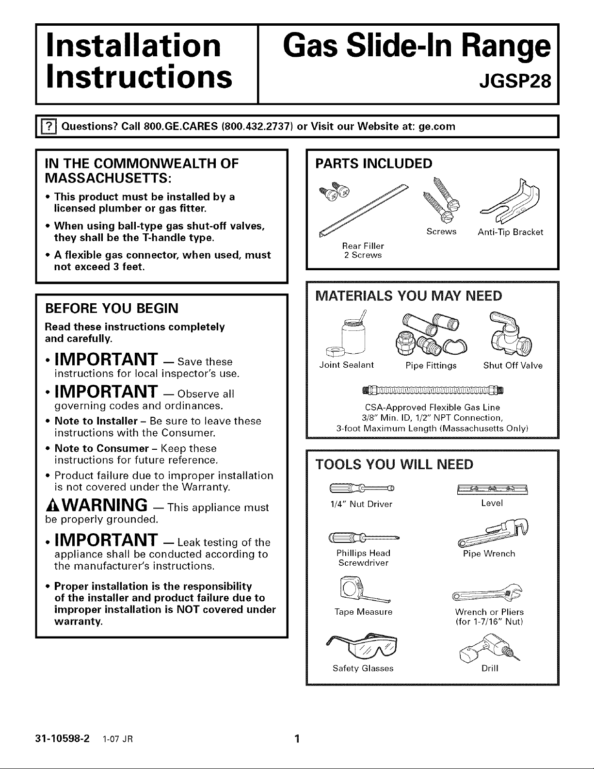
PARTS INCLUDED
Screws
Rear Filler
2 Screws
Anti-Tip Bracket
MATERIALS YOU MAY NEED
Joint Sealant
CSA-Approved Flexible Gas Line
3/8" Min. ID, 1/2" NPT Connection,
3-foot Maximum Length (Massachusetts Only)
Pipe Fittings
Shut Off Valve
• Note to Consumer - Keep these
instructions for future reference.
• Product failure due to improper installation
is not covered under the Warranty.
-_WARNING - This appliance must
be properly grounded.
• IMPORTANT - Leak testing of the
appliance shall be conducted according to
the manufacturer's instructions.
• Proper installation is the responsibility
of the installer and product failure due to
improper installation is NOT covered under
warranty.
TOOLS YOU WiLL NEED
1/4" Nut Driver Level
Phillips Head Pipe Wrench
Screwdriver
Tape Measure
Safety Glasses
Wrench or Pliers
(for 1-7/16" Nut)
Drill
31-10598-2 1-07 JR 1
Page 2
Installation Instructions
IMPORTANT SAFETY INSTRUCTIONS
FOR YOUR SAFETY:
WARNING - Ifthe+nformat+on
in this manual is not followed exactly, a fire,
explosion or gas leak may result, causing
property damage, personal injury or death.
Do not store or use gasoline or other
flammable vapors and liquids in the vicinity
of this or any other appliance!
WHAT TO DO IF YOU
SMELL GAS:
• Do not try to light any appliance. Do not
touch any electrical switch; do not use any
phone in your building.
• Immediately call your gas supplier from a
neighbor's phone. Follow the gas supplier's
instructions.
• If you cannot reach your gas supplier, call
the fire department.
This range has been design certified by
UNDERWRITERS LABORATORIES. You'll find
safety precautions in your Owner's Manual.
Read them carefully.
• Installation of this range must conform with
local codes or in the absence of local codes
with the National Fuel Gas Code, ANSI
Z223.1-Latest edition.
Be sure your range is installed properly by
a qualified installer or service technician.
To eliminate reaching over surface burners,
cabinet storage above burner should be
avoided.
• Do not install the unit near an outside door
or where a draft may affect its use.
Installation and service must be performed by
a qualified installer, service agency or the gas
supplier.
Page 3
Installation instructions
ELECTRICAL REQUlRMENTS
This appliance must be supplied with the
proper voltage and frequency and connected
to an individual, properly grounded branch
circuit, protected by a circuit breaker or fuse
having amperage as noted on the rating
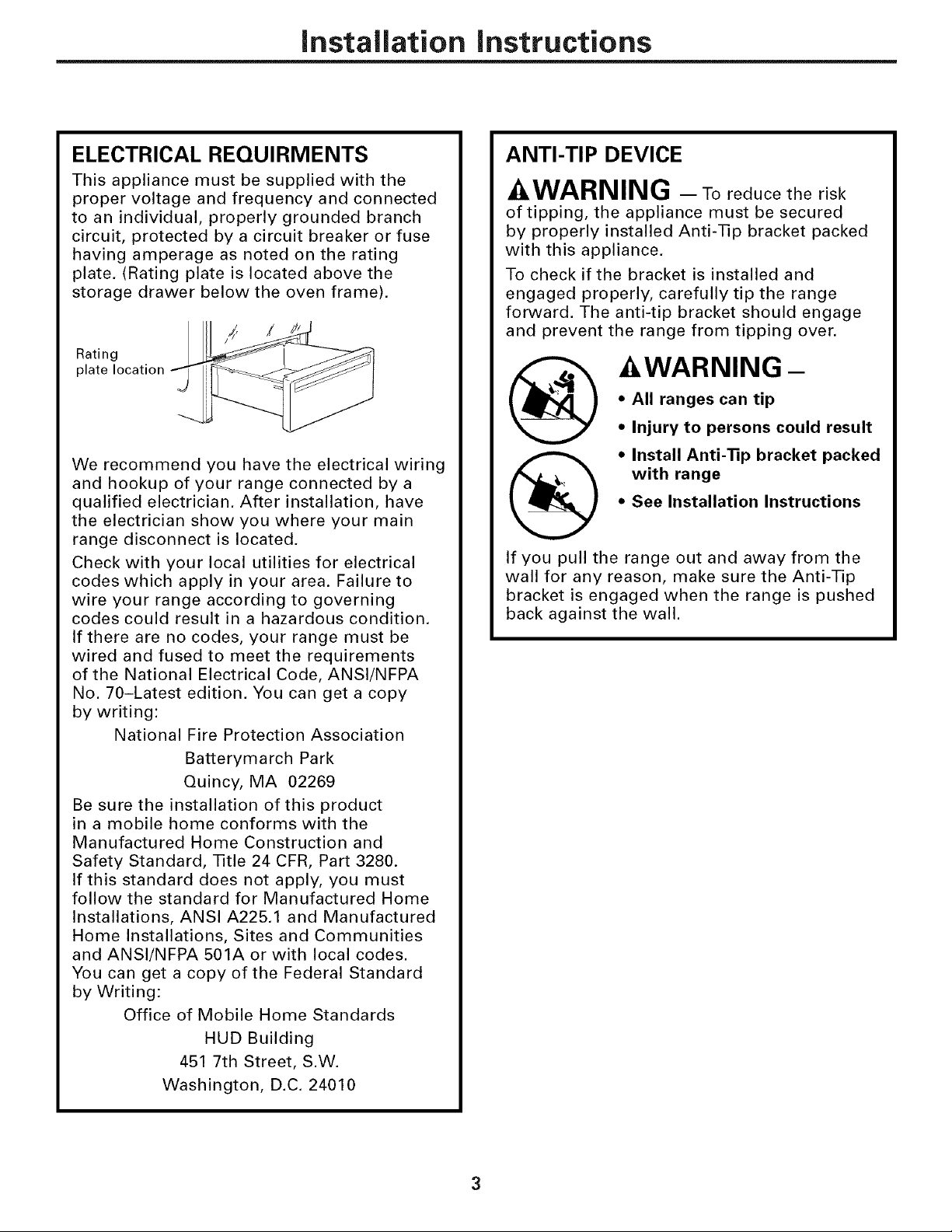
plate. (Rating plate is located above the
storage drawer below the oven frame).
Rating
plate location
We recommend you have the electrical wiring
and hookup of your range connected by a
qualified electrician. After installation, have
the electrician show you where your main
range disconnect is located.
Check with your local utilities for electrical
codes which apply in your area. Failure to
wire your range according to governing
codes could result in a hazardous condition.
If there are no codes, your range must be
wired and fused to meet the requirements
of the National Electrical Code, ANSI/NFPA
No. 70-Latest edition. You can get a copy
by writing:
National Fire Protection Association
Batterymarch Park
Quincy, IVIA 02269
Be sure the installation of this product
in a mobile home conforms with the
Manufactured Home Construction and
Safety Standard, Title 24 CFR, Part 3280.
If this standard does not apply, you must
follow the standard for Manufactured Home
Installations, ANSI A225.1 and Manufactured
Home Installations, Sites and Communities
and ANSI/NFPA 501A or with local codes.
You can get a copy of the Federal Standard
by Writing:
Office of Mobile Home Standards
HUD Building
451 7th Street, S.W.
Washington, D.C. 24010
ANTI-TIP DEVICE
AWARNING - Toreducetherisk
of tipping, the appliance must be secured
by properly installed Anti-Tip bracket packed
with this appliance.
To check if the bracket is installed and
engaged properly, carefully tip the range
forward. The anti-tip bracket should engage
and prevent the range from tipping over.
-&WARNING -
• All ranges can tip
• Injury to persons could result
• Install Anti-Tip bracket packed
with range
• See Installation Instructions
If you pull the range out and away from the
wall for any reason, make sure the Anti-Tip
bracket is engaged when the range is pushed
back against the wall.
Page 4
Installation Instructions
PRE-INSTALLATION CHECKLIST
ill iNSPECT iNSTALLATiON
LOCATION
Refer to alternate construction section for
the following non-standard installations.
[] Counter opening extends to the wall:
Maintop Filler (supplied with the range)
(see page 15 for Installation Instructions)
or Backguard Kit (JXS32XX).
[] Counter height greater than 36-3/4":
Lower Trim Slide-in (Kit JXS56XX).
[] One side is not enclosed by a cabinet:
Bodyside (Kit JXS77XX).
[] island Installation:
To provide an optimum installation, the
top surface of the countertop must be
level and flat (lie on the same plane)
around the 3 sides that are adjacent to
range cooktop. Proper adjustments to
make the top flat should be made or
gaps between the countertop and
range cooktop may occur. Forcing the
cooktop to fit may cause excessive gaps
and could chip the enamel cooktop.
_-I MOVE RANGE INDOORS IN
FRONT OF CABINET OPENING
Do not use hand trucks when moving the
unpackaged range. Cooktop enamel may
be chipped.
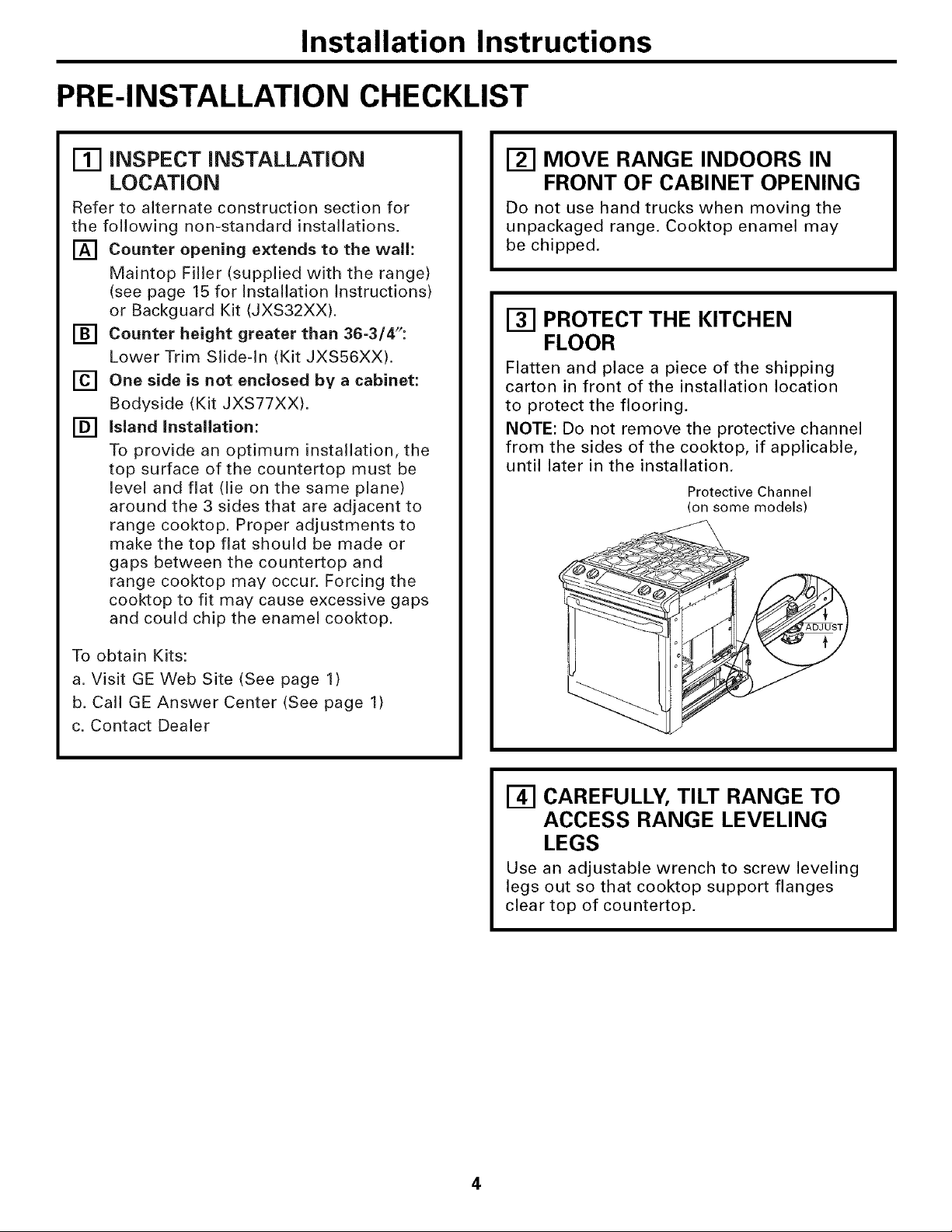
[] PROTECT THE KITCHEN
FLOOR
Flatten and place a piece of the shipping
carton in front of the installation location
to protect the flooring.
NOTE: Do not remove the protective channel
from the sides of the cooktop, if applicable,
until later in the installation.
Protective Channel
(on some models)
I
To obtain Kits:
a. Visit GE Web Site (See page 1)
b. Call GE Answer Center (See page 1)
c. Contact Dealer
_-I CAREFULLY, TILT RANGE TO
ACCESS RANGE LEVELING
LEGS
Use an adjustable wrench to screw leveling
legs out so that cooktop support flanges
clear top of countertop.
4
Page 5
Installation Instructions
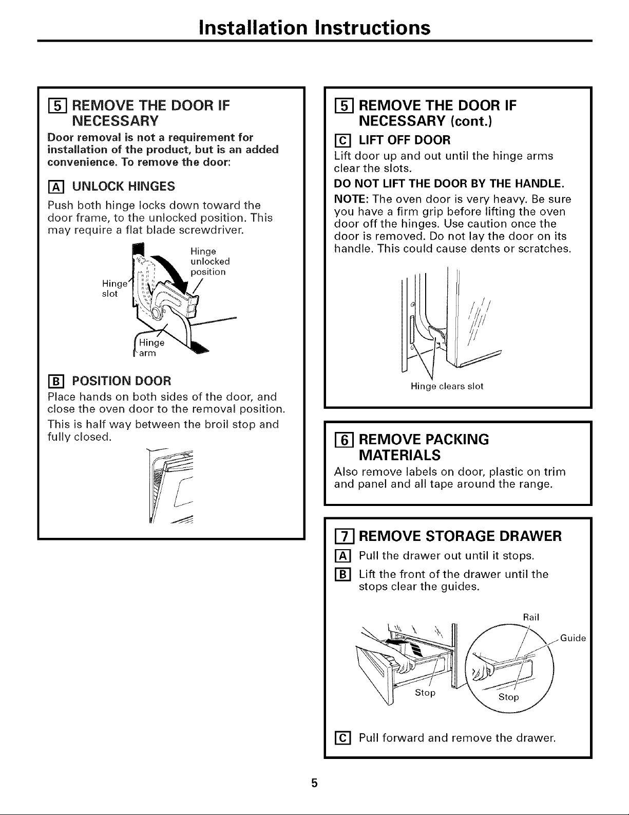
[_ REMOVE THE DOOR iF
NECESSARY
Door removal is not a requirement for
installation of the product, but is an added
convenience. To remove the door:
[] UNLOCK HINGES
Push both hinge locks down toward the
door frame, to the unlocked position. This
may require a flat blade screwdriver.
Hinge
unlocked
position
Hinge' /
slot
arm
[] POSITION DOOR
Place hands on both sides of the door, and
close the oven door to the removal position.
This is half way between the broil stop and
fully closed.
[] REMOVE THE DOOR IF
NECESSARY (cont.)
[] LIFT OFF DOOR
Lift door up and out until the hinge arms
clear the slots.
DO NOT LIFT THE DOOR BY THE HANDLE.
NOTE: The oven door is very heavy. Be sure
you have a firm grip before lifting the oven
door off the hinges. Use caution once the
door is removed. Do not lay the door on its
handle. This could cause dents or scratches.
Hinge clears slot
REMOVE PACKING
MATERIALS
Also remove labels on door, plastic on trim
and panel and all tape around the range.
[] REMOVE STORAGE DRAWER
[] Pull the drawer out until it stops.
[] Lift the front of the drawer until the
stops clear the guides.
Rail
Stop
[] Pull forward and remove the drawer.
Page 6

Installation instructions
PRE-INSTALLATION CHECKLIST (CONT.)
[] PRE-INSTALLATION CUTOUT AND REQUIRED CLEARANCES
If cabinets are placed less than 30" above the range,
see Alternate Construction, Step 19F, on page 16.
NOTE: Product meets ANSI Z21.1 requirements for 0"
clearance to back and side walls below the cooktop.
Wall coverings, counters and cabinets around range must
withstand heat (up to 194°F) generated by the range.
Follow instructions I
packaged with 4- 30" min. _1
alternate applia nce _1__ ]
6"min. fromwall_ _ __..._
• 1 I\ _---'-F3_from
For optu'num [_ 2,1" min_ I cooking surface
installation these to bottom of
surfaces must be overhead
flat and level, cabinets
_" 23-3/16 'F
-_ 13" max. 18" min. vertical distance
depth from the bottom of the
adjacent overhead cabinets
5"5 _rface
1"o front tertOP I
of coU_
OVERALL DEPTH _4_ I
_- 26-518"
Max. depth
of cord, plug, Countertop depth
35-7/8"-38" from
floor to countertop
recept, box & 25" (typical)
gas hookup
4" to prevent !1-1/4" min. countertop
interference top of drawer
with
electrical
outlet area
29-15/16" rain.
30-1/16" max.
STANDARD INSTALLATION
If the construction of your cabinet cannot provide a 1/4" flat area at the back of the countertop opening,
consider changing the countertop to accommodate this dimension. See Alternate Construction section.
Wall
-2 _ 1-13/16"
t
1/4" min,
flat
25 't
23-3/16" typically
9/16"
min.
flat
_ 29-15/16"-30-1/16" _1
)$ ,,
" NOTE: A 1-1/2 minimum space must be maintained between the rear edge of the cooktop and the rear wall above the cooktop.
smooth cut
9/!6"
flat
_. mln. _
I
Flat area
36"
1/4" _ _
q
6
Page 7

Installation Instructions
ELECTRICAL CONNECTIONS
INSTALLATIONmELECTRICAL
[]
CONNECTIONS
Because of potential safety hazards
[]
under certain conditions, we strongly
recommend against the use of an
extension cord. However, if you still
elect to use an extension cord, it is
absolutely necessary that it is a UL
listed 3-wire grounding-type appliance
extension cord and that the current
carrying rating of the cord in amperes
is equivalent to or greater than the
branch circuit rating. Such extension
cords are obtainable through your local
appliance dealer.
IMPORTANT: (Please read carefully)
FOR PERSONAL SAFETY, THIS
APPLIANCE MUST BE PROPERLY
GROUNDED.
[] An adequate electrical supply and
outlet must be used to operate the
electrical parts of your range.
• The power cord of this appliance is
equipped with a three-prong (grounding)
plug which must be used with a properly
grounded three-hole outlet with standard
120 Volt, 60 cycle AC household current.
• When a standard two-prong wall
receptacle is encountered, it is the
personal responsibility and obligation
of the customer to have it replaced
with a properly grounded three-prong
wall receptacle by a qualified electrician.
Do not under any circumstances cut or
remove grounding prong from the range
cord. Failure to provide proper ground
may create a hazardous condition.
Page 8

Installation Instructions
GAS CONNECTIONS
_] MAKING THE CONNECTIONS
15"
[]
Install a manual shut-off valve in the gas
supply line in an easily accessible location.
[]
Know how and where to shut off the gas
supply to the range.
[]
Shut off gas supply before removing an
old range. Leave it off until hookup of
new range is finished.
[]
Because solid pipe restricts moving the
range, we recommend use of a C.S.A.
certified flexible metal appliance
connector.
WARNING: Never reuse old
flexible connectors. The use of old flexible
connectors can cause gas leaks and personal
injury. Always use new flexible connectors
when installing a gas appliance.
[] Before making gas connections, make
sure that the oven shut-off lever (visible at
the back of range) is in the open position.
Gas supply to
top burners
[_] MAKING THE CONNECTIONS
(cont.)
[] Install 1/2" flare union adaptor to the 1/2"
NPT elbow on pressure regulator.
[] Connect flexible appliance connector to
flare union.
[] Move range into approximate position
and connect flexible connector to gas
supply line with proper flare union
adaptor.
Shut-off valve Flexible gas line
T f__X Pressure
Gas elbow _ U
supply ""*_u-_4_
line
[] To prevent gas leaks, put a pipe joint
sealant or Teflon ®tape on all male
threads. NOTE: Make sure sealant or tape
is compatible with Natural and LP gases.
[] When you are finished making
connections, be sure that all range knobs
are turned to OFF before you open the
main gas supply valve.
WARNING: oo not use a flame
to check for gas leaks. Use liquid leak detector
at all joints and connections to check for leaks
in the system.
supply _ _ It
tooven
Oven shut-off _ _
lever shown in
the op_
_ Pr;s_utr:r as
seen from
front of range
8
Page 9

Installation Instructions
INSTALL THE RANGE
I'_ INSTALL THE ANTI-TIP BRACKET
[] LOCATE THE BRACKET
a. Decide whether the bracket will be
installed on the right or left side of the
range opening.
b. Place the bracket as shown in Fig. 1.
Fig. 1
Adjacent
cabinet
/
FLOOR-CONCRETE
Bracket
side
Rear
leveling leg
FLOOR-WOOD
/
I'_ INSTALL THE ANTI-TIP BRACKET
(cont.)
[] INSTALL THE BRACKET IN WOOD
OR CONCRETE
INSTALLATION--WOOD CONSTRUCTIONS
a. Locate the centers of the 4 holes identified
in Fig. 1 as Floor-Wood and Wall.
b. Drill a 1/8" pilot hole through the
pre-marked areas. Note the angle of the
wall screw in Fig. 2.
c. Mount the Anti-Tip bracket with the
4 screws provided,
Top front Fig. 2
edge of
countertop _ 25" %/_---_1
--J woodor -_4.mJ:_==--_
Bracket I1
Screw \,_|_ Wall plate
must enter r4:i t
INSTALLATIO N--CO NCRETE
CONSTRUCTIONS
a. For concrete installation, you will need
two 1/4" x 1-1/2" lag screws and two sleeve
anchors.
b. Locate the center of the 4 holes identified
in Fig. 1 as Floor--Concrete and Wall. Drill
the recommended size holes in each,
c. Install the sleeve anchors into the
predrilled concrete holes and install the
lag and wall screws through the Anti-Tip
bracket. Make sure the screws are securely
tightened.
Page 10

Installation Instructions
INSTALL THE RANGE (CONT.)
SLIDE RANGE iNTO OPENING
[]
[]
Position the range in front of the cabinet
opening.
[] Make sure that the cooktop edges that
overhang the countertop clear the
countertop. If necessary, raise the unit
by lowering the leveling legs.
[] Push while lifting the range into the
opening, until the range is within 2"
of engaging the anti-tip bracket.
[] Remove the protective trim from the side
of the cooktop (if provided).
[] Using the adjustable pliers or wrench,
carefully screw in the back leveling leg
until the cooktop overhang comes to rest
on the countertop.
r_ SLIDE RANGE INTO OPENING
(cont.)
[] Plug the range cord into the receptacle.
Locate the cord in the back of the range
in a manner that it will not touch or be
moved by the drawer.
\
/////
.\
\
tll
\x
\
\
/11
Position range cord
so that there is no
interference with
11ili!iiiiill
// // /// /////_//
[] Carefully screw in the front two leveling
legs (similar to Step E) until the cooktop
overhang touches the countertop.
[] Carefully push the range into the opening
until the anti-tip bracket engages and the
vertical sides are flush with the cabinet.
Couotertop
Cabinet_
r_-z-4]FINAL CHECK OF ANTI-TIP
BRACKET
When installation is complete and the range is
in place, check to be sure that the rear leveling
leg is fully inserted into the slot of the Anti-Tip
Bracket.
10
Page 11

Installation Instructions
REPLACE THE OVEN DOOR
NOTE: The oven door is heavy. You may need
help lifting the door high enough to slide it
into the hinge slots. Do not lift the door by
the handle.
[] Lift the oven door by placing one hand on
each side. The door is heavy, so you may
need help. Do not lift the door by the handle.
[] With the door at the same angle as the
removal position (halfway between the
closed and broil stop position), seat the
notch of the hinge arm into the bottom
edge of the hinge slot. The notch of the
hinge arm must be fully seated into the
bottom of the slot.
Hinge arm
Bottom edge
[] REPLACE THE STORAGE
DRAWER
[] Place the drawer rail on the guides.
[] Push the drawer in until it stops.
[] Lift the front of the drawer and push
in until the stops clear the guides.
[] Lower the front of the drawer and push
in until it closes.
SPECIAL INSTRUCTIONS IF YOU ARE
HAVING PROBLEMS WHILE REPLACING
THE STORAGE DRAWER
If Drawer Won't Close:
Drawer
Drawer does front panel
Power cord not close _ . tipped away
may be comnletel,, Itear (]rawer from body
obstructing " Y support is side
drawer in _ I_ resting on top _l/_
] this area In I of guide rail I_
of slot !
Hinge notch
[] Fully open the door until it is parallel to
the floor. If the door will not fully open,
the notch in the hinge is not seated
correctly in the bottom edge of the slot.
Repeat steps A and B if necessary.
[] Push the hinge locks up against the front
frame of the oven cavity, to the locked position.
Hinge in
locked position
Notch of hinge
secu rely fitted
into bottom of
hinge slot
Remove and replace, making sure the power
cord is not obstructing the drawer and/or the
rail is in the guide.
If Drawer is Crooked:
Rear drawer
support is on top
of guide rail on Drawer front panel
the high side _ tippeito one side
Remove and replace, making sure the rail is in
the guide.
[] Close the oven door.
11
Page 12

Installation Instructions
INSTALL THE RANGE (CONT.)
r_] COOKTOP BURNERS
[] ASSEMBLE THE BURNERS
CAUTION: Theelectrodeofthe
spark igniter is exposed. Be careful not to
snag the electrode of the spark igniter with
a cleaning cloth. Damage to the igniter could
occur. Be careful not to turn on any cooktop
controls while cleaning. A slight electrical
shock might result, which could cause you
to knock over hot cookware.
a. Place burner heads over the electrodes
on the cooktop, in the correct locations
according to their sizes.
Medium head Small head
and cap and cap
o
I'_ COOKTOP BURNERS (cont.)
[] ASSEMBLE THE BURNERS (cont.)
c. Place the matching size caps onto the heads.
Make sure that the heads and caps are
placed in the correct locations.
Place the vent grille, grates and air inlet
cover onto the cooktop, making sure that
the grates lock the vent grille in place.
G rate
Burner cap
Burner head
Cooktop
Electrode
Vent grille
Air inlet cover
Front of range t
Large head Large head
and cap and cap
b. Make sure the slot in the burner head is
positioned over the electrode.
/
[] CHECK FOR LEAKS
Turn the gas supply on and use a liquid leak
detector (soap solution) at all joints and
connections to check for leaks. Do not use an
open flame to look for leaks. Be sure all leaks
are stopped before lighting burners.
12
Page 13

Installation instructions
[] PRESSURE TEST INFORMATION
The maximum allowable supply pressure for
the regulator is 14" W.C. The minimum supply
pressure needed to check the regulator setting
is 7" W.C. for natural gas and 10" W.C. for LP gas.
WARNING: The range and its
individual shut-off valve must be disconnected
from the gas supply piping system during any
pressure testing of the gas supply system at
test pressures of more than 1/2 psig (pounds
per square inch gauge). The range must be
isolated from the gas supply piping system by
closing its individual shut-off valve during any
pressure testing of the gas supply system at
test pressures equal to or greater than 1/2
psig. NOTE: 1/2 psig = 13.855" w.c.
[] CHECK THE IGNITERS
Operation of the electric igniters should be
checked after the cool(top and supply line
have been carefully checked for leaks and the
cool(top has been connected to the electrical
power.
a. Turn on gas.
b. Push and turn a burner valve to the LITE
position.
• The burner valve should light when gas
is available to the burner.
= Once the burner lights, it should be
turned out of the LITE position.
c. Try each valve separately until all burners
have been checked.
[] BURNER IGNITION
Cool(top Spark Ignition--When you turn
the cool(top knob to LITE, the spark igniter
makes a series of electric sparks (ticking
sounds) which light the burner. During a
power failure the burners will not light
automatically. In an emergency, a cool(top
burner may be lit with a match by following
the steps below.
WARNING: Lighting gas burners
with a match is dangerous. You should match
light the cool(top burners only in an
emergency.
a. Light a match and hold the flame near the
burner you want to light. Wooden matches
work best.
b. Push in and turn the control knob slowly.
Be sure you are turning the correct knob
for the burner you are lighting.
NOTE: If the burner does not light within
five seconds, turn the knob off and wait five
minutes before trying again.
[] BURNER FLAMES
Turn each burner on. Turn each burner knob
to the high position. Flames should be blue
in color with little or no trace of yellow. The
burner flames should not flutter or blow away
from the burner. The inner cone of the flame
should be between 1/2" and 3/4" long. If the
burner flames are yellow in color or not the
proper length, call GE Service.
_,,_j1/2" to 3/4" _ _t---
Flames should circle burner
Burners should be checked frequently.
WARNING: Ifyouattempt to
measure the inner cone of the flame, please
use caution. Burns could result.
13
COOKTOP
BURNER
Page 14

Installation instructions
INSTALL THE RANGE (CONT.)
[] BAKE AND BROIL BURNERS
If the bake and/or broil burners have lifting or
"lazy" (floating) flames or you have a yellow
flame, perform the following procedures:
[] CHECKING THE OVEN BURNERS
To check the bake burner flames with the
oven door in the closed position:
1. Open the door and remove it.
2. Remove the oven racks.
3. Remove the oven bottom,
Lift the oven bottom up at rear and pull
forward.
4. Remove the four screws holding the burner
baffle (flame spreader) to the burner box.
5. Install and close the oven door.
6. Turn on the bake burner.
As you watch the flames, check the
following:
• Burner flames should not flutter or blow
away from the burner.
• They should be blue in color with no trace
of yellow.
The broil burner flames may be seen without
removing the racks, oven bottom or bake
baffles.
[] ADJUST THE AIR SHUTTER
BAKE BURNER
1. Remove the orifice fitting cover.
2. Use a screwdriver to loosen the air shutter
screw.
3. Adjust the air shutter to 11/32".
4. Retighten the air shutter screw.
Orifice fitting
÷...
-_--_. -_. _JJ
WHAT ADJUSTMENT TO MAKE:
a. If the flames are yellow, open the air
shutter more than the original setting.
b. If the flames blow away or fluttered from
the burner, close the air shutter more than
the original setting.
Burners should be checked frequently.
BROIL BURNER
1. The broil burner is located and accessible
in the top rear of the oven.
2. Using a
screwdriver,
loosen the air
sh utter
adjustment screw.
3. Make the air
sh utter
adjustment.
4. Retighten the air
shutter screw,
5. Check the inner
cone of the flame.
It should be
between 1/2" and
3/4" long for the
oven bake and
broil burners.
WHEN ALL ADJUSTMENTS ARE MADE AND
THE RESULTS ARE SATISFACTORY
1. Replace the orifice fitting cover.
2. Replace the burner baffle (flame spreader)
and screws.
3. Replace the oven bottom.
4. Replace the oven door.
1/2"to 3/4" i_Z Oven broiler,
Dim. "A"
Air shutter
adjustment screw
Inner cone of
flame
14
shutter
Page 15

Installation instructions
[] ALTERNATE CONSTRUCTION
PREPARATION
[] OPTIONAL MAINTOP FILLER OR
BACKGUARD KIT
If counter opening extends to the wall, it will
require Maintop Filler Kit (supplied with the
range) or Backguard Kit (JXS32XX) to close
the gap.
NOTE: If the countertop is greater than 25",
it will show a gap between the backguard
and wall or between filler kit and the wall.
If the countertop is less than 25", a gap will
occur between the countertop front and the
control panel ends (see Step 13G).
If you are using the optional backguard kit,
refer to the backguard kit instructions for
installation details.
m m __
J
S
Wall
25 tt
Must _J _ 30"
be | smooth cut
flat _ Must be level
31-1/8"
If you use the filler kit, place the metal filler
piece supplied with the range to the back
of the range as shown in the figure below.
Start the 2 screws into the upper holes at the
outside rear of the range above the louvers
and through the slots in the trim, holding
the filler piece centered on the maintop
frame and pushing upward to close the gap
between the bottom of the cooktop and the
filler trim.
Must be
level
flat
_" Must be
When the trim is set in the proper position,
tighten the 2 mounting screws. The top of
the trim should be located below the cooktop
edge to prevent pots, pans and skillets from
damaging the painted parts.
Refer to the Standard Installation of the
Range on page 6.
/ J
I'_ _ (2) #8
screws
[] FOR NON-BUILT-IN INSTALLATION
(END OF CABINET LOCATION)
When installing the range at the end
of a cabinet section which will expose the
unfinished side of the range, use Body Side
Kit (JXS77XX). Refer to the kit instructions for
installation details.
[] ISLAND INSTALLATION
Attach the Anti-Tip bracket per instructions in Step
12, making sure that the rear of the bracket is 25"
from the front of the countertop.
Be aware that the screws provided are long and
may penetrate through the back of the island
cabinets. In this event, use shorter screws (not
provided) or the screws provided should be used
in the floor (see Step 12B for Wood/Concrete Floor
Installation).
Do not use Backguard Kit JXS32XX.
15
Page 16

Installation instructions
INSTALL THE RANGE (CONT.)
r_] ALTERNATE CONSTRUCTION
PREPARATION (cont.)
[] FOR CABINET OPENINGS
APPROXIMATELY 30-3/8"
If range is installed in cabinet opening
approximately 30-3/8", the Vertical Side Trim Kit
(JXS86XX) should be used to cover gaps between
range sides and cabinet. Refer to the kit
instructions for installation details.
[] CABINETS OVER THE RANGE LESS
THAN 30"
If a 30" clearance between cooking surface and
overhead combustible material or metal cabinets
cannot be maintained, protect the underside of the
cabinets above the cooktop with not less than 1/4"
insulating millboard covered with sheet metal not
less than 0.0122" thick.
[] OPERATION CHECKLIST
• Double check to make sure everything in
this guide has been completed. Rechecking
steps will ensure safe use of the cooktop.
• Make sure all controls are left in the OFF
position.
• Make sure the flow of combustion and
ventilation air to the cooktop is unobstructed.
• The serial plate for your Range is located
under the oven door above the storage
area. In addition to the model and serial
numbers, it tells you the ratings of the
burners and the type of fuel and pressure
the cooktop was adjusted for when it left
the factory.
• When ordering parts, always include the
serial number and model number to ensure
proper replacement parts.
• Recheck Steps: Double check to make sure
everything in this guide has been completed.
Rechecking steps will ensure safe use of
the Range.
Please see L.P. conversion instructions
supplied with this range when L.P. Gas
is used.
NOTE: Instructions are mounted on
regulator bracket.
IN SOME CASES
[] With L.P. gas, some yellow tipping
on the outer cone is normal.
[] Foreign particles in the gas line may
cause an orange flame at first, but this
will soon disappear.
SPECIAL NOTE:
To convert the oven back to natural gas,
reverse the instructions given in making
L.P. Adjustments.
Once the conversion is complete
and checked ok, fill out the LP
sticker and include your name,
organization and the date the
conversion was made. Apply the sticker near
the regulator to alert others in the future that
this appliance has been converted to LP gas.
If converting back to natural gas from LP,
please remove the sticker so others know the
appliance is set to use natural gas.
ADJUSTING LOW FLAME SETTING
ON COOKTOP BURNERS
Low setting adjustments must be made with
two other burners in operation on a medium
setting. This procedure prevents the low
flame from being set too low, resulting in the
flame being extinguished when other burners
are turned on.
[] Remove the valve control knobs.
[] Through the opening, locate the valve
bypass screw located on the lower right
side of the valves.
[] Using a small screwdriver, screw down
the bypass screw fully in a clockwise
rotation.
16 Printed in the United States
 Loading...