

GEAppliances.com
0
0
Safety Instructions .... 2-7
Operating Instructions
Downdraft Vent System . .l 0
Features .............. 8
(;as Surface Burners ..... 9
Using Your Cooktop .... 10
Care and Cleaning
Burner Assemblies ..... l l
Burner Caps and Heads . .11
Burner Grates and
Vent Grille ............ 12
Control Knobs ........ 13
Glass Surface ....... 13, 14
Vent Filter ............ 12
Installation Instructions
Ductwork ....... 19-22, 27
Electrical
Connections .... 23, 28, 29
Exhaust Blower Ratings .21
Final Assembly ........ 30
Installing
the Cooktop ....... 25-28
Installing the Gasket .... 24
Power Supply ......... 23
Preparation ........ 17-19
Safety Precautions ...... 15
Unpacking
the Cooktop ....... 16, 24
Troubleshooting
Tips .............. 31,32
Consumer Support
Consumer
Support ....... Back Coxer
Product
Registration ........ 33, 34
Warranty ............. 35
jcP 98 9
Write the model and serial
numbers here:
Model #
Serial #
Eind these numbers on a label
under the cooktop, on the side
of the vent chamber:
164D4290P347 49-80797 02-03 JR
IMPORTANTSAFETYINFORMATION.
READALLINSTRUCTIONSBEFOREUSING.
WARNING!
For your safe_, the information in this manual must be followed to minimize the risk of fire or
explosion, electric shock, or to prevent property damage, personal injury, or loss of life.
WARNING:If the information in this manual
is not followed exactly, a fire or explosion may
result causing property damage, personal injury
or death.
-- Do not store or use gasoline or other flammable
vapors and liquids in the vicinity of this or any
other appliance.
- WHATTODOIF YOUSMELLGAS
Do not try to light any appliance.
Do not touch any electrical switch; do not use
any phone in your building.
Immediately call your gas supplier from a
neighbor's phone. Follow the gas supplier's
instructions.
If you cannot reach your gas supplier, call the
fire department.
-- Installation and service must be performed by
a qualified installer, service agency or the gas
supplier.
2
GEAppliances.com
IMPORTANTSAFETYNOtiCE
The California Safe Drinking Water and ToxicEnforcement Act requires the Governor of California to
publish alist of substances known to the state to cause cancer, birth defects or other reproductive
harm, and requires businesses to warn customers of potential exposure to such substances.
Gasappliances can cause minor exposure to four of these substances, namely benzene, carbon
monoxide, formaldehyde and soot, caused primarily by the incomplete combustion of natural gas or
LP fuels. Properly adjusted burners, indicated by a bluish rather than a yellow flame, will minimize
incomplete combustion. Exposure to these substances can be minimized by venting with an open
window or using a ventilation fan or hood.
SAFETYPRECAUtiONS
Have the installer show you the location of the cooktop gas shut-off valve and how to shut # off
ff necessary.
Hm_ your cooktop installed and ploperly
gTounded by a qualified installe_; in
accordance with the Installation
Instructions. Any adjusunent and service
should be performed only by qualified gas
cooktop installers or service technicians.
Do not attempt to repair or replace any
part of your cooktop unless it is specifically
recommended in this manual. All other
service should be refened to a qualified
technician.
i,ocam fire cooktop out of kitchen traffic
padx arrd out of drafty locations to prex>nt
poor burner performance.
Plug your cooktop irrto a 190_\olt
gTounded outlet only. Do not remove the
round grounding prong flom tire plug.
If ira doubt about the grounding of the
home elecuical sysmm, it is your personal
responsibility arrd obligation to have an
ungrounded outlet replaced with a
properly glounded, three-prong outlet in
accordance with the Nauonal Elecuical
Code. Do not use an exmnsion cord with
this appliance.
let fire burner grams and odrer smt_aces
cool before touching them or leaving
them where children can reach them.
Be sure all packaging materials are
remoxed flom tire cooktop before
operating it to prexent fire or smoke
damag> should the packaging material
ignite.
Be sure your cooktop is conecdy adjusted
by a qualified service mchnician or irrstaller
fox the wpe of gas (natural or I,P) which
is to be used. Your cooktop can be
corrxerted fox use with either type of gas.
See tire Installation Instructions in the
I,P Corrx>rsion Kit.
WARNING: xesea ,xstmerrtsre.st
be made by a qualified service technician
in accordance with the mamd_acturer's
irrstructions arrd all codes arrd
requirements of the amhofitv having
jurisdiction. Failure to tbllow these
irrsUucfions could xesult in serious inju U
or properw damage. The qualified
agency perforating this work assumes
responsibility fox the corwersion.
Do not lem> children alone or unattended
whexe a cooktop is hot or in operation.
They could be seriously bmTaed.
Do not allow arryone to climb, stand or
hang on the cooktop.
Do not operam or clean your cooktop if
the glass is broken or cracked. Cleaning
solutions arrd spilloxers could peneuam the
broken cookmp and cream a risk of
electric shock. (;all fox service immediately
if the cooktop glass breaks or cracks.
3
IMPORTANTSAFETYINFORMATION.
READALLINSTRUCTIONSBEFOREUSING.
SAFETYPRECAUTIONS
CAUTION: ,emsofi,,,eFest,o
children shouM not be stored in cabinets
above a cooktoi>--<hildren climbing on tile
cooktop to reach imms could be seriously
i,ljured.
Alwws kee I) wooden and plastic umnsils
and canned food a safe distance away from
your cookmp.
A]wws kee I) combustible wall coxefings,
curtains or drapes a safe distance flom
your cookmp.
Never wear loose-fitting or hanging
garments while using the appliance.
Be caieflfl when reaching for imms staled
in cabinets ox>r tile cookmp. Flammable
mamrial could be ignimd if brouOlt in
contact widl flame or hot surPaces and
mav catlse severe btliTis.
Teach children not to play with tile controls
or any other part of the cooktop.
For your safety, never use your appliance
fbr warming or heating tile room.
Alwws kee I) dish towels, dishcloths, pot
holders and other linens a safe distance
flom your cooktop.
Do not store flammable materials near
a cooktop.
Do not store or use combustible materials,
gasoline or other flammable vapors and
liquids in tile vicinity of this or any other
appliance.
Do not let cooking grease or other
flammable mamrials accumulate on or
near tile cooktop.
Do not operam tile burner without all
burner parts in place.
Do not place hot cookware on tile glass
cooktop. This could cause glass to break.
Do not clean tile cooktop with flammable
or x_latile cleaning fluids.
Nexer use die cooktop as a cutting boaM.
Do not use water on grease fires. Nexer
pick up a flaming pan. Turn tile conuols
off: Smother a flaming pan on a suri_ce
burner by covering the pan complemly with
a well-fitting lid, cookie sheet or fiat tray
Use a multi-puq)ose d_T chemical or
foam-type file extinguisher
Flaming giease outside a pan can be put
out by coxering it with baking soda oi; if
available, by using a multi-puq)ose dU
chemical or foam-type fire exfinguishen
WARNING:ro reduce the risk of fira,
electrical shock, or injury to persons, observe the
following:
A. Use this tlnit on]v iI1 tile mamler intended
by file mamd_cnlren If you hax> questions,
contact tile manufl_ctmen
B. Before servicing or cleaning the unit,
switch power off at service panel.
C. When cutUng or drilling into wall or
ceiling do not damage electrical wiring
and other hidden utilities.
D. Ducted fans must a]wavs be x>nted to
tile outdoors.
E. To reduce tile risk of fire, use only meta]
ductwork.
WARNING:ro reduce the risk of a
cooktop grease fire:
A. Kee I) thn, fihers and greaseqaden surPaces
clean.
B. Alwws uml x>nt ON when cooking at
high heat.
C. Use high settings on cookmp only when
necessa U. Heat oil slowly on low m
medium setting.
D. Don't leaxe file cooktop unatmnded
when cooking.
E. AIwws use cookware and utensils
appropnam for file type and amount
of food being p_epared.
CAUTION:For general ventilating use
Do not clean tile cooktop when tile
appliance is in use.
4
Avoid scratching the cooktop with shaq)
instruments, or with rings and otherjeweh T.
only. Do not use to exhaust hazardous or
explosive materials and vapors.
GEAppliances.com
GLASSCOOKTOPSURFACEronsomemodels)
Use care when touching the glass cooktop surface. Theglass surface of the cooktop will retain heat
after the controls have been turned off.
Avoid scratching tile glass cooktop surface.
Tile glass sn,_tce call be scratched with
items such as shall) instruments, iings or
otherjeweh T and lix>ts on clothing.
image scratches or impacts m glass
cookmps can lead to broken or shatmied
glass.
Do not operam tile cooktop if tile glass is
broken. Spilloxers or cleaning soludon m W
penetrate a broken cooktop and create a
Iisk of electrical shock. Contact a qualified
technician immediately should your glass
cookmp surface become broken.
Nexer use the glass cookmp surPace as a
cutting board.
Do *lot place or store items that can melt
or catch fire on tile glass cookmp surface,
even when it is not being used.
Be carefld when placing spoons or other
sdrling utensils on glass cooktop surPace
when it is in use. Tiley m W become hot
and could cause 1)urns.
Clean tile cooktop surt=ace with caution.
If a wet spong_ or cloth is used to wipe
spills on a hot surPace, be carefld to ax_id
smam bnrrls. Some cleaners can produce
noxious fllmes if applied to a hot surface.
NOTE: _A'erecommend that you m_id
wiping any surface areas until they have
cooled and file indicator light has g_ne
off: Sugar spills ale tile exception m this.
Please see Cleaning the glass cooktop
surface sect.ion.
When file cooktop is cool, use only
CERAMA BRYTE c'_'Ceramic Cooktop
Cleaner and tile CERAMA BRYTE '_>
Cleaning Pad to clean tile cooktop.
To ax_id possible damage to tile cooking
surface, do *lot apply cleaning cream to tile
glass surface when it is hot.
After cleaning, use a d U cloth or paper
towel to iemoxe all cleaning cream residue.
Read and follow all insuucdons and
waming:s on tile cleaning cream labels.
5
IMPORTANTSAFETYINFORMATION.
READALLINSTRUCTIONSBEFOREUSING.
WARNING!
SURFACEBURNERS
Use proper pan size--a void pans that are unstable or easily tipped. Select cookware haring flat
bottoms large enough to cover burner grates. Toavoid spillovers, make sure cookware is large
enough to contain the food properly. This will both save cleaning time and prevent hazardous
accumulations of food, since heavy spattering or spillovers left on cooktop can ignite. Use pans
with handles that can be easily grasped and remain cool.
Always use fl_e LITE posit.ion when igniung
the top burners and make sure file burners
have ignited.
Nexer leaxe file surface burners unatmnded
at high flame setdng:s. Boiloxers cause
smoking and g_easy spilloxers dlat may
catch on file.
Use only dU pot holders--moist or damp
pot holders on hot surfaces may Iesult in
burJ_s flom steam. Do not let pot holders
come near open flames when lifting
cookware. Do not use a towel or other
bulky cloth in place of a pot holden Such
cloths can catch file on a hot bumen
When using glass cookware, make sure
it is designed for cooktop cooking.
To minimize the possibility of bur]is,
igniuon of flammable matelials and
spillage, t/lI'll cookwaIe handles toward
the side or cenmr of the cooktop without
exmnding oxer adjacent burners.
a]wws t/lill the sml_ace burner controls off
before iemoving cookware.
Carefldlv watch foods being flied at a high
flame setung.
Alwws heat l_at slowly and watch as it heats.
Do not leave any imms on flae cooktop.
Tile hot air flom the \_nt m W ignite
flammable items and will increase pressure
in closed containers, which m W cause
them to burst.
If a combinauon of oils or fats will be used
in flTing, sfis tog>ther befoie heating or as
fats meh slowly.
Do not use a wok on tim cooking surface
if file wok has a round metal ring that is
placed ox>r file burner grate to support
file wok. Tiffs ring acts as a heat trap, which
m W damag_ the burner grate and burner
head. Also, it m W cause die burner to
work improperly. This m W cause a carbon
monoxide lexel abox> dlat allowed by
cmxent standards, iesulting in a health
hazard.
Foods for ruing should be as dry as
possible. Frost on flozen foods or moistule
on flesh foods can cause hot l_atm bubble
up and o_er die sides of the pan.
Use file least possible amount of fat for
effecfixe shallow or deep-fat flTing. Filling
file pan too fldl of fat can cause spillo_>rs
when food is added.
Use a deep fat thermometer whenever
possible to pre_>nt oveflleafing fat beyond
file smoking point.
Nexer ti T to move a pan of hot fat,
especially a deep fi_triTer VVaituntil file fi_t
is cool.
_llen flaming foods, turIl the fan off: Tile
fan, if operaung, m W spread the flames.
GEAppliances.com
SURFACEBURNERS
Adjust the burner flame size so it does not extend beyond the edge of the cookware. Excessive flame
is hazardous.
Do not leave plastic items on the cooktoI>--
riley may melt if left too close to file \_nt.
Keep all plastics away from tile sur/_ace
b/IFllei's,
If you smell g¢_s, turn off the gas to the
cooktop and call a qualified service
technician. Nex_r use all open flame to
locate a leak.
To ax_id file possibility of a bum, always be
certain that tile controls for all burners are
at file off position and all grates are cool
before attempting to remox_ them.
Nex_r clean the cooktop suiPace when it is
hot. Some cleaners produce noxious fimles
and wet cloflls could cause steam bums if
used on a hot sur/_ace.
Ne_>r leave jars or cans of/_t drippings
on or near your cooktop.
Do not use a]umimlm foil under bm_ler
gxams. Misuse could lesult ill a fire hazard
or damag_ to file cooktop.
Do not coxer or block tile area around
file cooktop knobs. This area must be kept
clear for proper x_nfilafion and burner
performance.
Clean only parts listed ill fills Owner's
Manual.
COOKMEATANDPOULTRYTHOROUGHLY...
Cookmeat and poultry thoroughly--meat to at least an INTERNAL temperature of 160°F and poultry to at least
an INTERNAL temperature of 180°E Cooking to these temperatures usually protects against foodbome i#ness.
CONVERTINGTOLPGAS(or converting back to natural gas from LP)
This cooktop leaves the factory set for use with natural gas.
If you want to com_rt to LP gas, die com_rsion must be perforated by a qualified LP gas
installei:
Tile conversion instructions, conversion sticker and LP orifices call be found attached to file
cooktop next to file pressure regulator.
Tilere is a second set of instructions included ill the envelope containing file product wiring
diagrams on file side of file cooktop. Keep fllese instructions and the orifices in case you want
to com_rt back to natural gas.
READANDFOLLOWTHISSAFETYINFORMATIONCAREFULLY.
SAVETHESEINSTRUCTIONS
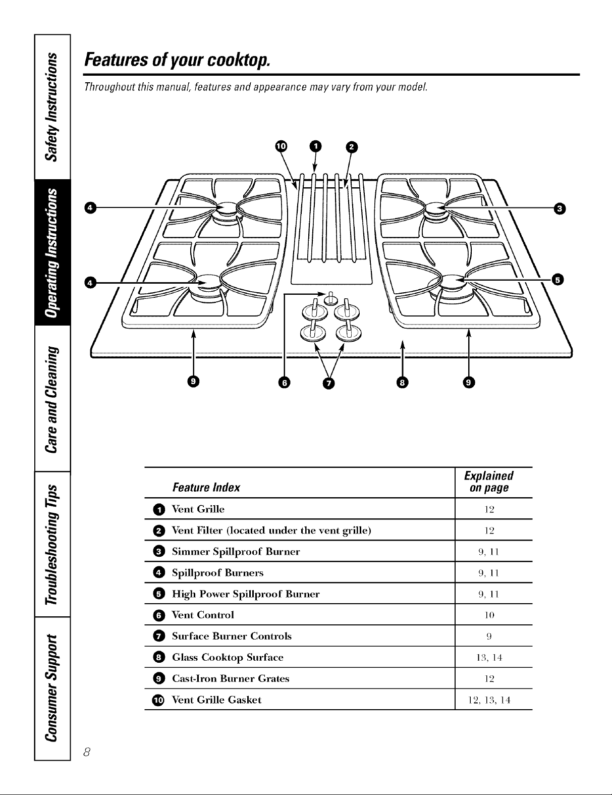
Featuresof yourcooktop.
Throughout this manual, features and appearance may vary from your model.
¢
¢
0
0
Explained
Feature Index onpage
O Vent Grille 12
Vent Filter (located under the vent grille) 12
Simmer Spillproof Burner 9, 11
O Spillproof Burners 9, 11
0 High Power Spillproof Burner 9, 11
Vent Control 10
Surface Burner Controls 9
0 Gl&ss Cooktop Surface 13, 14
Cast-Iron Burner Grates 12
_) Vent Grille G_sket 12, 13, 14
8
Usingthe gas surfaceburners. GEAppliances.com
Throughout this manual, features and appearance may vary from your model.
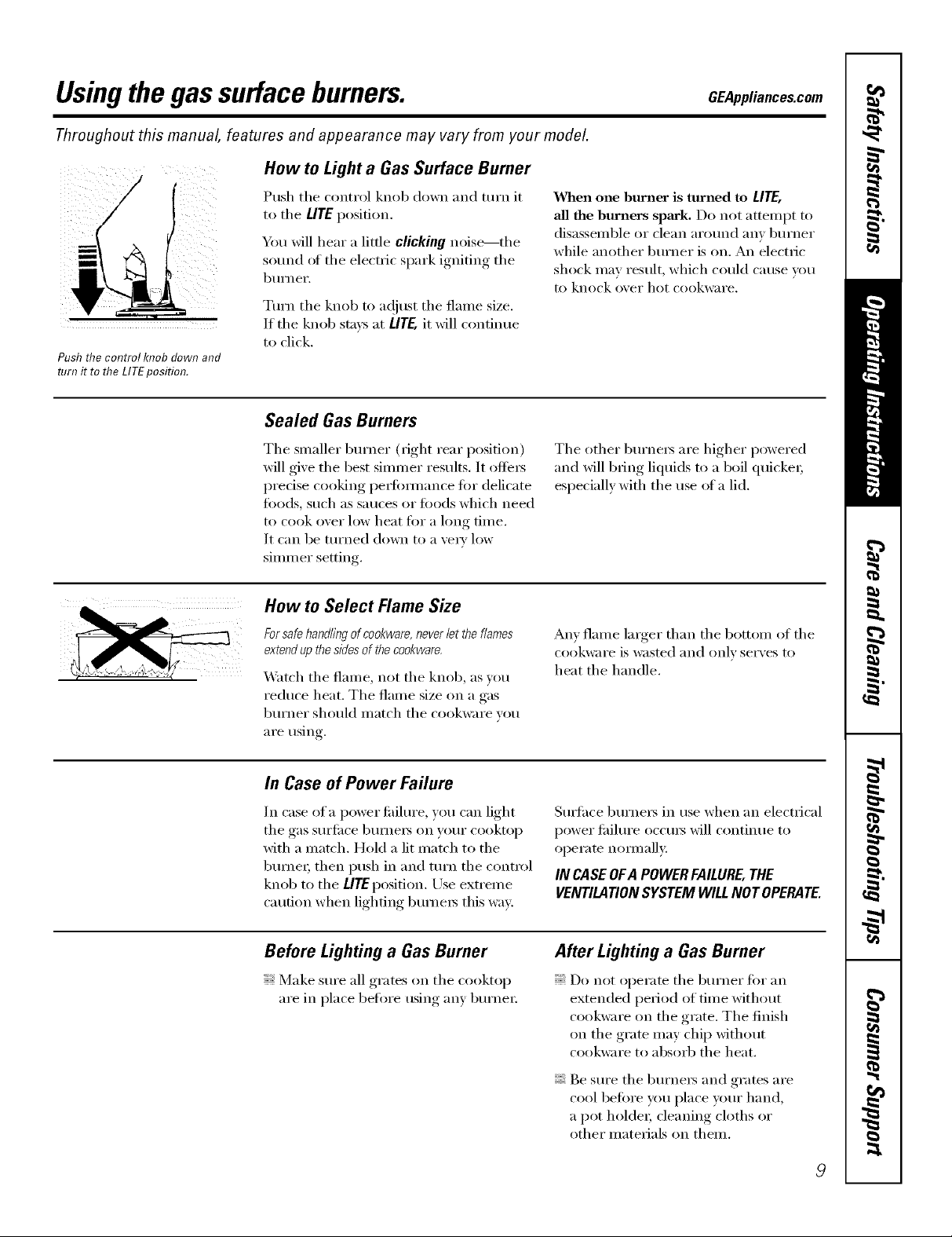
How to Lighta GasSurface Burner
Push tile control knob down and mrn it
to tile LITEposition.
You will hear a little clicking noise---the
sound of tile electric spark igniting tile
btlI'neF.
Tm'n tile knob to a(!just tile flame size.
If the knob stms at LifE, it will continue
to click.
Push the control knob down and
turn it to the LITEposition.
Sealed Gas Burners
When one burner is tttnmd to LITE,
all the burners spark, Do not attempt to
disassemble or clean around anv burner
while another burner is on. An electric
shock inav result, which could cause you
to knock over hot cookware.
Tile smaller bm'ner (right rear position)
will give the best simmer results. It offers
predse cooking perlommnce fi)r delicate
fi)ods, such as sauces or foods which need
to cook over low heat fi)r a long time.
It can be turned down to a ve_' low
simm er setting.
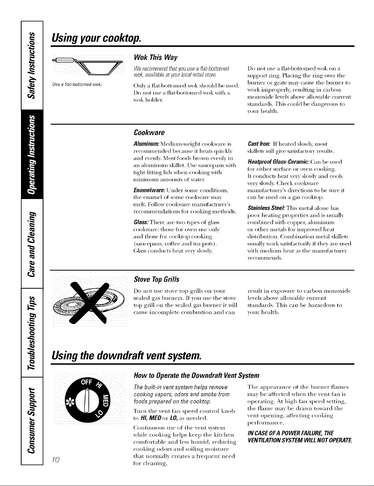
How to Select Flame Size
Forsafe handling of cookware, never let theflames
extend up the sides of theco&ware,
Watch tile flame, not tile knob, as you
reduce heat. The flame size on a gas
burner should match tile cookware vou
are using.
In Case of Power Failure
In case of a power fifilm'e, you can light
tile gas surli_ce bume_ on your cooktop
with a match. Hold a lit match to tile
bume_; then push in and mrn tile control
knob to tile LifE position. Use extrelne
caution when lighting burners this way.
Tile other burners are higher powered
and will bring liquids to a boil quicke_;
especially with tile use of a lid.
An) flame larger than tile bottom of tile
cookware is wasted and OillV ser\ es to
heat tile handle.
Stwthce bm'nets in use when an electrical
power tifilm'e occms will continue to
operate n(mnallv:
IN CASE OFA POWERFAILURE,THE
VENTILATIONSYSTEM WILLNOT OPERATE.
Before Lighting a Gas Burner
Make sm'e all grates on tile cooktop
are in place befi)re tlsiil_*,manv, b/IYneI'.
After Lighting a Gas Burner
Do not operate tile burner for an
extended period of time without
cookware on tile grate. Tile finish
on tile grate may chip without
cookware to absorb tile heat.
Be sure the burners and grates are
cool befi)re you place your hand,
a pot holder; cleaning cloths or
other materials on them.
9
Usingyourcooktop.
Wok This Way
Werecommendthatyouusea flat-bottomed
wok,availableatyour/oca/retai/store.
Use a flat-bottomed wok.
Only a flat-botton/ed wok should be tlsed.
Do not use a flat-bottolned wok with a
wok holdei:
Cool(ware
Do not rise a I']at-bottoilled wok on a
support ring. Placing tile ring over tile
burner or grate Inay cause tile burner to
work inlproperly, i'esuldng in carbon
nionoxide levels above allowable current
standards. This could be dangerous to
your health.
Aluminum:Mediuin-weight cookware is
recoimnended because it heats quickly
and evenly. Most fi)o(ls brown evenly in
an ahuninuin skillet. Use saucepans with
tight fitting lids when cooking with
iilinililtllil alilOtlnts ofwatei:
Enamelware:/_Jildei soIne conditions,
tile enalllel of SOIlle cookware niav
inelt. Follow cookware illanH[ilctHi'ei"s
reconmiendations fi)r cooking inethods.
Glass: There are two types of glass
cookware: those for ()veil rise only
and those fi)I" cooktop cooking
(saucepans, coffee and tea pots).
Glass conducts heat veIa' slowly.
Stove TopGrills
Do not rise stove top grills on VOtli"
sealed gas burners. If you use tile stove
top grill on tile sealed gas burner it will
cause incoinplete conibusfion and can
CastIron:If heated slowly,n/ost
skillets will give satisfi_ctorv results.
HeatproofGlass-Ceramic:Can be used
fk)i" either StllS{il('e o1" oven cooking.
It conducts heat veI T slowly and cools
very slowly. Check cookware
nlanufi_cturer's directions to be sure it
C_lll be used on _1 g_ls cooktop.
Stainless Steel: This n/etal alone has
poor heating properties and is usually
coinbined with coppei, ahuninuin
or other inetals fi)r iinproved heat
disti_ibufion. (_oinbinafion inetal skillets
usually work satisfactorily if they are used
with niediuni heat as tile i/ian/ithcttlrer
i'ecolili//ends.
result in exposure to carbon nionoxide
levels above allowable current
standards. This can be hazardous to
your health,
Usingthedowndraft ventsystem.
How to Operate the Downdraft Vent System
Thebuilt-in ventsystem helps remove
cooking vapors, odors and smokefrom
foods prepared onthe cooktop.
Turn tile vent tan speed control knob
to HI,IVIEDor LO,as needed.
Continuous use of tile vent svsteIn
while cooking helps kee I) tile kitchen
cointi)rtable and less hunIid, reducing
cooking odors and soiling nioisture
10
that norniallv creates a frequent need
ti)i" cleaning.
Tile appearance of tile burner flaines
inav be afl'ected when the vent tan is
operating. At high tim speed setting,
the flaine inav be drawn toward the
vent opening, afl'ecting cooking
pe i'J[O IIIl _1nce,
IN CASEOFAPOWERFAILURE,THE
VENTILATIONSYSTEMWILLNOTOPERATE.
Careand cleaningof thecooktop. CEAppliances.com
Be sure electrical power is off and all surfaces are cool before cleaning any part of the cooktop.
Sealed Burner Assemblies
Gra /
Burnercad
@ Burnerhead
ectrode
I
{_Z_ Burnerbase
/
_, CAUTION:Do not operate the
burner without all burner parts in
place.
Turn all controls OFF beflwe removing
the burner parts.
The burner grates, caps and burner
heads can be lifted off, making them
easy to clean,
Burner Caps and Heads
NOTE'.Beforeremoving theburnercaps
andheads,remembertheir sizeand location.
Replacethem in thesamelocationafter
cleaning.Thebumer headsandbumerbases
are labeledA, Band C to aid reassemb/g
\
Electrode
When one burner is tin'ned to
LITE, all tile bm'ners spark. Do not
attempt to disassemble or clean
around any burner while another
bm'ner is on. An electric shock
may result, which could cause you
to knock over hot cookware.
AfterCleaning
Before putting tile bm'ner caps and
heads back, shake ()/It excess water and
then (hw them thoroughly by setting in
}1l_;lil/l (Well J()I" .'40 II/intltes.
After cleanhTg make sure the
notch h7the burner head is
positioned toward the electrode.
Rotatethe burner head around the
burner base until it is level and
securely seated.
Burner Caps
IJfl off when cool. X&'ashburner caps
in hot, soapy water and rinse with clean
water: You may scour with a plastic
scorning pad to remove burned-on
food particles.
Burner Heads
Theshts /b theburnerheadsof your cooktop
mustbekept dean at a// times for an even,
unhamperedflame.
You should clean tile sm'fi_ce 1)urne_
routinely, especially after bad spilh)vers,
which could clog these openings, Lift off
when cool,
To remove bm'ned-on fi)od, soak tile
bm'ner heads in a solution of mild
liquid detergent and hot water fi)r
20-30 mimltes. For nlore stubborn stains,
use a toothbrush.
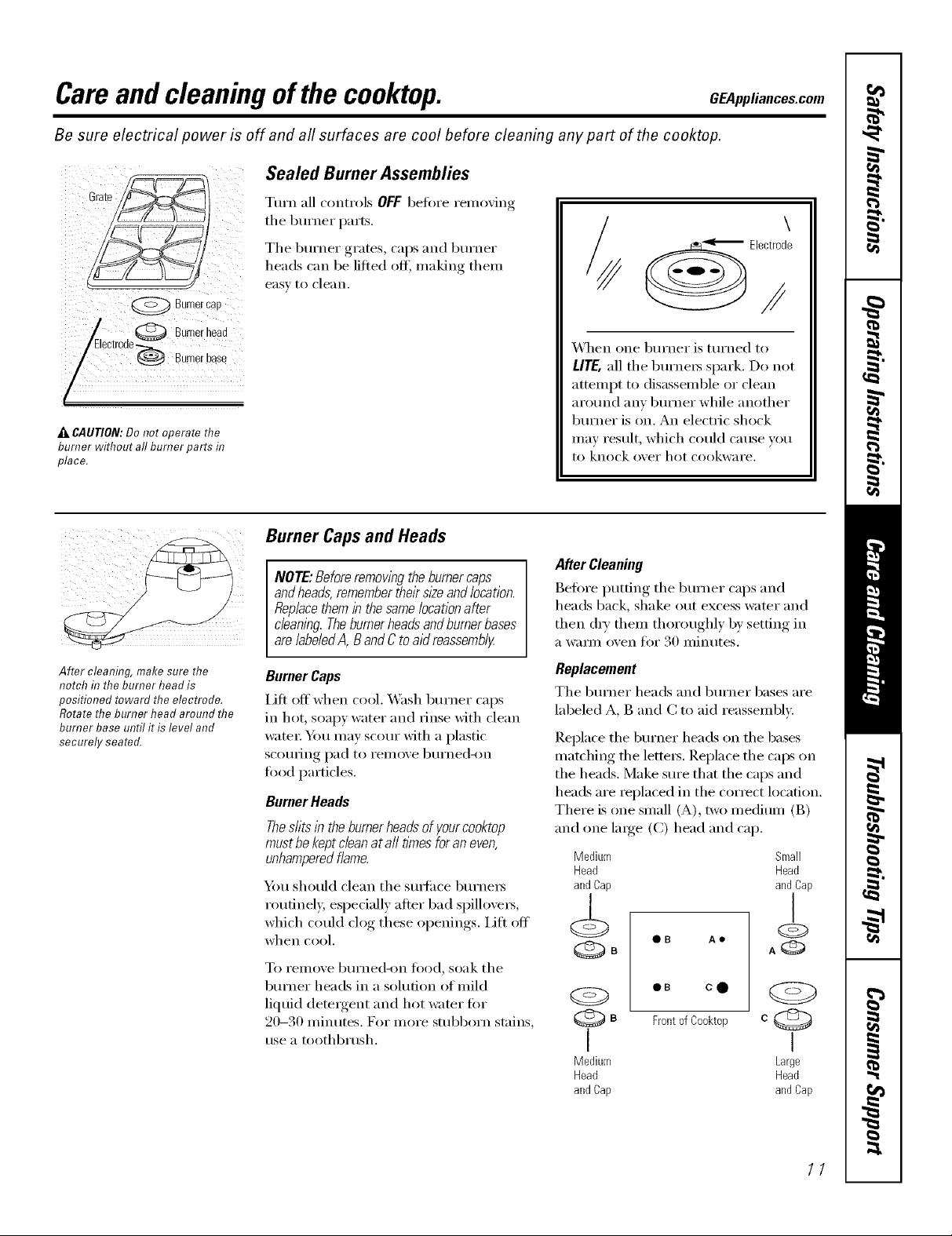
Replacement
Tile burner heads and burner bases are
labeled A, B and C to aid reassembE.
Replace tile burner heads on tile bases
matching file letters. Replace tile calls on
the heads, Make sm'e that the caps and
heads are replaced in the correct location.
There is one small (A), two medium (B)
and one laroe_ (C) head and cap.
Medium Small
Head Head
andCap andCap
QB Ae
eB cO
Frontof Cooktop
I I
Medium Large
Head Head
andCap andCap
11
Careand cleaningof thecooktop.
Burner Grates and Vent Grille
Appearance may var,A
Thegrate legs have one brass foot
and three rubber feet. Toorder
replacement rubber grate feet,
please call our toll-free number:
National
Parts Center ......... 800.626.2002
RubberGrate Feet .. #WBO2T10101
i,ifl off when cool. (;rates and grille
shouM be washed regularly and, of
coui_e, after spillove_. _'ash them in hot,
soapy water and i_nse with clean watei;
Discoloration on the grates may also be
removed by using the provided cooktop
cleaning cream. Apply a drop or two on a
damp cloth and mb across the discolored
area. Rinse and oh> _Mier cleaning,
replace the burner grates and make
sure they, are positioned securely, over
the burne_.
To i'elllO&e btlFned-on too(l, t/se a soap-
filled scom_ing pad.
_Mthough they are din'able, the grates will
gradually lose their shine, regardless of
the best care xou can gixe them. This is
due to their COllfinual exposure to high
temperatm'es. You will notice this sooner
with lighter color grates.
Do not operate a burner for an extended
period of time without cookware on the
burner grate. The finish on the grate may
chip without cookwa_e to absorb the heat.
Replacement
Before repladng the vent grille, make
sm'e the grille gasket is properly installed
arotmd the downdralt vent opening, with
the word "FRONT" toward the knobs.
Replace the vent grille carefully over
the gasket.
X._]mn replacing the grates, make sm'e
they are positioned with their brass
locator teet to_m'd the center
Grille__
Ven!Gri" Gasket
Br
LocaterFeet_ -'-_
NOTE'.Donot dean thegrates, grille or grille
gasketin a se/f-c/eanl)_goven.
Thegrates, grille andgri//egasket maybe
cleanedin a dishwashe_
Toorder replacement filters, please
call our toll-free number:
National
Parts Center ......... 800.626.2002
Filter .............. #WBO2X10651
12
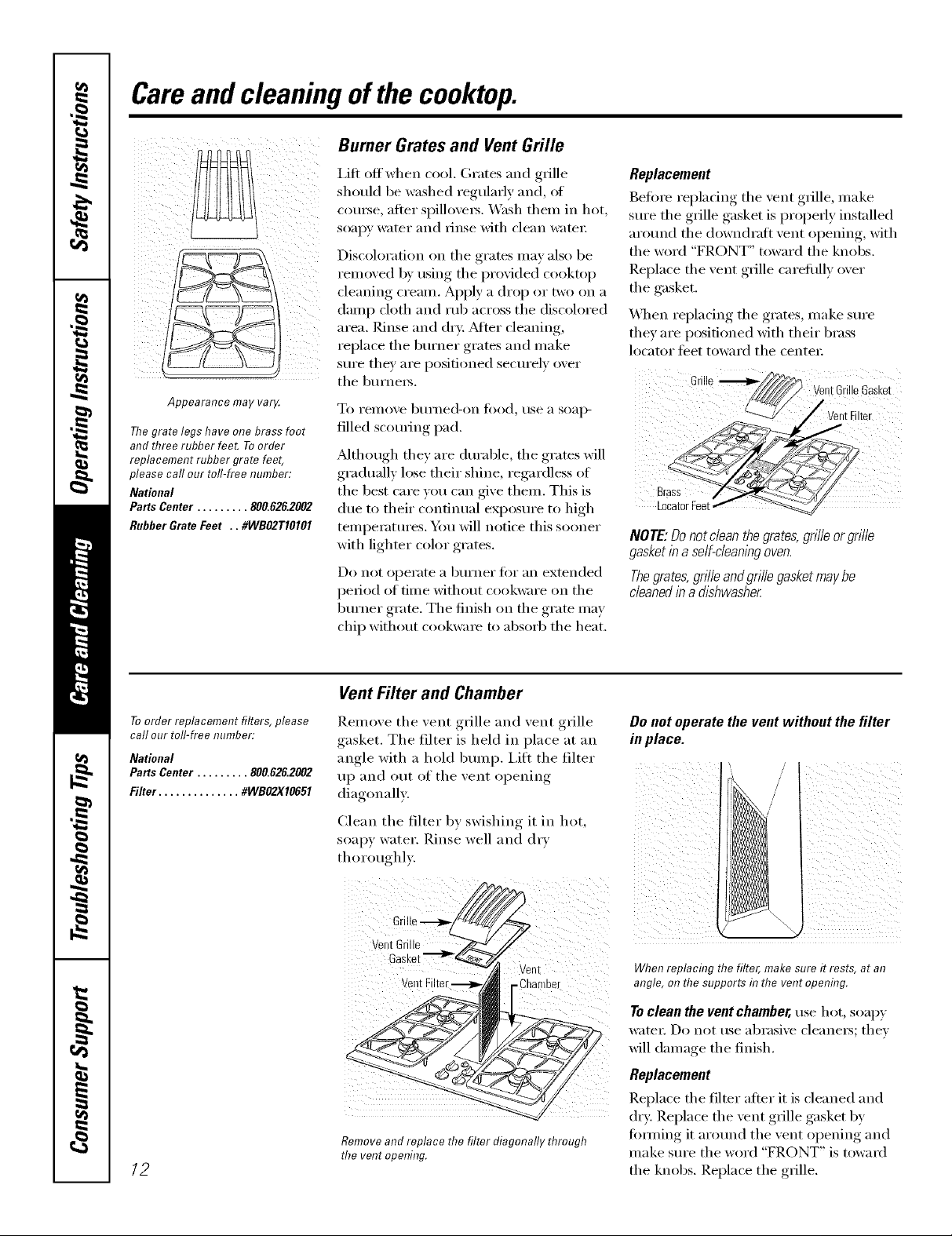
Vent Filter and Chamber
Remove the vent grille and vent grille
gasket. The filter is held in place at an
angle with a hold bmni), i,ifl the filter
up and out of the vent opening
diagonall>
Clean the filter by swishing it in hot,
soapy water. Rinse well and d_T
thoroughl).
Remove and replace the filter diagonally through
the vent opening.
Donotoperate the vent withoutthefilter
inplace.
When replacing the filter, make sure it rests, at an
angle, on the supports in the vent opening.
Toclean the vent chamber, tlse hot, soapy
watex: Do not use abrasive cleanex_; thev
will damage the finish.
Replacement
Replace the filter after it is cleaned and
dry: Replace the vent grille gasket by
fimning it around the vent opening and
make sm'e the word "FRONT" is toward
the knobs. Replace the grille.
GEAppliances.com
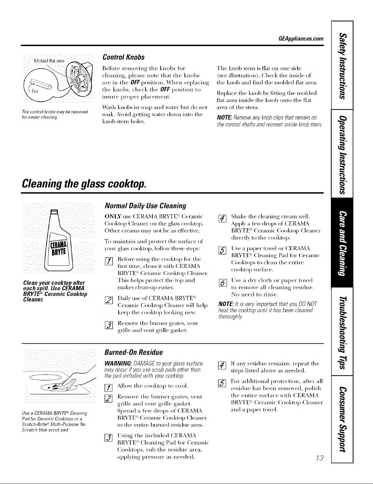
Moldedflatarea
The control knobs may be removed
for easier cleaning.
Control Knobs
Beflwe removing the knobs fi_r
cleaning, please note that the knobs
are in the OFFposition. When replacing
the knobs, check the OFF position to
insure proper placement.
_'_sl_ knobs in soap and water but do not
soak. Avoid getting water down into the
knob stein holes.
Cleaningthe glasscooktop.
Normal Daily Use Cleaning
ONLY use CEIL_d_JlABRYTE _'Ceramic
Cooktop Cleaner on the glass cooktop.
Other creams ma_ not be as eflecfixe.
To maintain and protect the sm_i_ce _ff
yore" glass cooktop, tollow these steps:
[] getOre using the cooktop tot the
fi_t time, clean it with CEIL_d_4A
BRYTE '_Ceramic Cooktop Cleane_:
Cleanyourcooktopafter
eachspill. Use CERAMA
BRYTE® CeramicCooktop
Cleaner.
This helps protect the top and
makes clean-up easier:
[] Daft) use of CEI_/]A BRYTE (_)
Ceramic ('xx)ktop Cleaner will help
keep the cooktop looking ne_:
] Remoxe the burner grates, xent
grille aim xent grille gasket.
The knob stein is fiat on one side
(see illustration). Check the inside of
the knob and find the molded flat area.
Replace the knob by fitting the molded
fiat area inside the knob onto the fiat
area of the stem.
NOTE:Removeanyknobclipsthatremainon
thecontrolshaftsandreinsertinsideknobstem.
[] Shake the cleaning cream well.
Appl} a few drops of CEIL_dMA
BRYTE _ Ceramic Cooktop Cleaner
direcflv to the cooktop.
[] Use a p_per towel or CEI_L_dMA
BRYTE _-Cleaning Pad tot Ceramic
Cooktops to clean the entire
cooktop Stli-J[ilce.
[] Use a (h T cloth or paper towel
to remove all cleaning residue.
No need to rinse.
NOTE: It is very important that you DO NOT
heat the cooktop until it has been cleaned
thorough/_
Use a CERAMABRYTE'_ Cleaning
Pad for Ceramic Co&tops or a
Scotch-Brite ®Multi-Purpose No
Scratch blue scrub pad.
Burned-On Residue
WARNING'. DAMAGE to your glass surface
may occur if youuse scrub pads other than
the pad included with yourcooktop.
[] Allow the cooktop to cool.
] Remove the burner grates, xent
grille and vent grille gasket.
Spread a few drops of CERMMA
BRYTE ')Ceramic Cooktop Cleaner
to the entire bm'ned residue area.
Using the included CERAMA
[]
BRYTE _' Cleanin,, Pad fi)r Ceramic
Cooktops, mb the residue area,
aii))lxing,, pressure as needed.
[] If any residue remains, repeat the
steps listed above as needed.
[] For additional protection, after all
residue has been remoxed, polish
the entire sm'tace with CERAMA
BRYTE': Ceramic Cooktop Cleaner
and a paper towel.
13

Cleaningtheglass cooktop.
Heavy, Burned-On Residue
TheCERAMA BRYTE'*_Ceramic
Cooktop Scraper and all
recommended supplies are
available through our Parts Cente_
See flTstructions under "To Order
Parts" section below.
NOTE:Do not use a dull or
nicked blade.
[] Allow the cooktop to cool.
] Remoxe the burner grates, xent
grille and xent grille gasket.
[] Use a single-edge razor blade
scraper at approximately a 45 °
angle against the glass surtace and
scrape the soil. It will be necessary
to apply pressure to the razor
scraper in order to remove the
residue.
Metal Marks and Scratches
Be careflfl not to slide pots and pans
across your cooktop. It will leave metal
markings on the cooktop surtace.
These marks are remow_ble using
the CEI_&_MA BRYTE ': Ceramic
Cooktop Cleaner with the CERAMA
BRYTE '_Cleaning Pad fi_r Ceramic
Cooktops.
WARNING'. Carefully check the bottom
of pans for roughness that would scratch
the cooktop.
[] Afier scraping with the razor
scraper, spread a few drops of
CER,_d_/IA BRYTE ': Ceramic
Cooktop Cleaner to the entire
btu'ned residue area. Use the
CERAMA BRYTE _ Cleaning Pad
to remove any remaining residue.
[] For additional protection, alter all
residue has been remoxed, polish
the entire surtace with CERAMA
BRYTE': Ceramic Cooktop Cleaner
and a paper towel.
Glasssurface potential for permanent damage.
Our testing shows that if
you are cooking high sugar
mixtures such as jelly or
fudge and have a spillover,
it can cause permanent
damage to the glass surface
unless the spillover is
immediately removed.
14
Damage from Sugary Spills and Melted Plastic
[] Turn off all surtace burners and,
with an o',en Illitt, rei/lo',e hot
pans and grates.
[] XA'earing an oven mitt:
a. Use a single-edge razor blade
scraper (CERAMA BRYTE )
Ceramic Cooktop Scraper) to
move the spill to a cool area
on the cooktop.
b. Remove the spill with
paper towels.
To Order Parts
To order CERA_MA BRYTE _ Ceramic
Cooktop Cleaner and the cooktop
scrape_; please call our toll-free iltlillbei':
National Parts Center 800.626.2002
CERAMA BRYTE®
Ceramic Cooktop Cleaner .... # WXIOX300
[] Any remaining spilloxer should be
lett until the surthce of the cooktop
has cooled.
] Don't use the surtace units again
until all of the residue has been
completely removed.
NOTE: If pitting or indentation in theglass
surface has already occurred, the cooktop
glass will have to be rep/acecL/n this case,
service wifl be necessary
CERAMABRYTEc")
CeramicCooktopScraper ..# WXIOXO302
Kit ...................... # WB64X5027
(Kitincludescreamandrazorscraper)
CERAMABRYTE®CleaningPadsfor
CeramicCooktops........... #WXIOX350

Gas Downdraft
Ilnstallation
nstruct ons
If you have questions, call 800.GE.CARES (800.432.2737) or visit our Website at: GEAppliances.com
Cooktop
INTHECOMMONWEALTHOFMASSACHUSET[S:
• This product must be installed by a licensed
plumber or gas fitter.
• When using ball-type gas shut-off valves, they
shall be the T-handle type.
• A flexible gas connector, when used, must not
exceed 3 feet.
BEFORE YOU BEGIN
Read these instructions completely and carefully.
•IMPORTANT -Savetheseinstructions
for local inspector's use.
•IMPORTANT - Observeallgoverning
codes and ordinances.
• Note to Installer - Be sure to leave these
instructions with the Consumer.
• Note to Consumer - Keep these instructions for
future reference.
• Unless very knowledgeable in the installation of
this product, engage a professional installer.
• Proper installation is the responsibility of the
installer.
• Product failure due to improper installation is
not covered under the Warranty.
FOR YOUR SAFETY
If You Smell Gas:
1. Open windows.
2. Don't touch any electrical switches.
3. Extinguish any open flame.
4. Immediately call your gas supplier.
Do not store or use gasoline or other flammable
vapors and liquids in the vicinity of this or any other
appliance.
WARNING- Beforebeginning the
installation, switch power off at the service panel
and lock the service disconnecting means to
prevent power from being switched on accidentally.
When the service disconnecting means cannot be
locked, securely fasten a prominent warning device,
such as a tag, to the service panel.
IMPORTANT SAFETY INSTRUCTIONS
The cooktop has been design certified by CSA
International. As with any appliance using gas and
generating heat, there are certain safety precautions
you should follow. You'll find these precautions in the
Important Safety Information section in the front of
this Owner's Manual. Read them carefully.
• Be sure your cooktop is installed properly by a
qualified installer or service technician.
*The cooktop must be electrically grounded in
accordance with local codes, or in their absence,
with the National Electrical Code ANSI!NFPA
No. 70 - Latest Edition.
• Installation of this cooktop must conform with local
codes, or in the absence of local codes, with the
National Fuel Gas Code ANSI Z223.1 - Latest Edition.
• Improper installation, adjustment, alteration,
service or maintenance can cause injury or property
damage. Refer to this manual. For assistance or
additional information, consult a qualified installer,
service agency, manufacturer (dealer) or the gas
supplier.
• Disconnect electrical supply before servicing.
• Never reuse old flexible connectors. The use of old
flexible connectors can cause gas leaks and personal
injury. Always use NEW flexible connectors when
installing a gas appliance.
• Make sure the wall coverings around the cooktop can
withstand heat generated by the cooktop up to 200°E
•Avoid placing cabinets above the cooktop.
• If cabinets are placed above the cooktop, allow a
minimum clearance of 30" between the cooking
surface and the bottom of unprotected cabinets.
• If cabinets are placed above the cooktop, use
cabinets no more than 13" deep.
• If a 30" clearance between cooking surface and
overhead combustible material or metal cabinets
cannot be maintained, protect the underside of the
cabinets above the cooktop with not less than 1/4"
insulating millboard or gypsum board at least 3/16"
thick covered with 28 gauge sheet steel or 0.020"
thick copper.
• Clearance between the cooking surface and protected
cabinets MUST NEVER BE LESSTHAN 24."The
vertical distance from the plane of the cooking
surface to the bottom of adjacent overhead cabinets
extending closer than 1" to the plane of the cooktop
sides must not be less than 18."
15

Installation Instructions
UNPACKING YOUR COOKTOP
PARTS INCLUDED (PACKED BELOW THE COOKTOP)
• Blower assembly
• Blower plenum
• (4) Nuts
• (2) Hold-down retainers and
thumb screws
• (9) Sheet metal screws
• Foam gasket tape (9-ft. roll)
• Vent grille
• Vent filter
Sheet Metal
Screws (9)
Hold-Down
Retainers and
Screws
• Vent grille gasket
• Cleaning cream
• Scrub sponge or scraper
(on some models)
• Burner grates
• Burner heads
(1 small (A), 2 medium (B),
1 large (C))
Burner /[===(C===2j==_
Grate /_1
Vent Grille
• Burner caps
(1 small, 2 medium, 1 large)
• Gas pressure regulator
• Attached 120-volt grounded
plug cord
• LP Conversion
t2t
Regulator
Cleaning
Cream
CAUTION: GLASS
IS FRAGILE
DO NOT BUMP EDGE
OF GLASS DURING
INSTALLATION
Scrub Sponge
@
Foam Gasket Tape
Burner Caps and Burner Heads
Burner Cap and Burner Head
Vent Grille Gasket
CAUTION:
DO NOT LIFT
FROM VENT
OPENING
Burner Cap and Burner Head
Blower Assembly and Blower Vent
(4) Mounting Nuts 16 Plenum Filter

Installation Instructions
PREPARATION
TOOLS AND MATERIALS
YOU WILL NEED
• Saw
• Duct tape
• Measuring tape or scale
• Carpenter's square
• Adjustable wrench or socket set (7/16" socket and
ratchet)
• Drill and drill bit
• 1/4" nut driver
• Sheet metal screws
• Pipe wrench
• Manual gas line shut-off valve
• Pipe joint sealant that resists action of LP gas
• Ductworkto suit the installation
For rigid connection:
• Shut-off valve
• Union
• Pipe fittings as required
For flexible connection where local codes permit:
• Flexible metal tubing (same 3/4" or 1/2" I.D. as gas
supply line)
30" COOKTOP (DIMENSIONS FOR REFERENCE ONLY)
Unit shown fully assembled.
21%"
..,,,1_ 201/2,,_
Unit must be vented to the outside!
297/Z'
283/4"
V
I 6"
A
17

Installation Instructions
CABINET PREPARATION
[] PREPARING FOR INSTALLATION
Positioning the cooktop
The cooktop is designed to look best when centered
in a cabinet at least 30" wide.
The exhaust vent beneath the cooktop must be
located between wall studs or floor joists so that the
ductwork may be installed properly.
13" max._q_ 4
depth of _- |
unprotected S/L J I I
overhead HI I I I
cabinets _l I I I
| 30" min.
|clearance from 18" min. height
| countertop : from countertop
_-to unprotected to nearest cabinet
overhead surface on either side of
the unit
I
5" min.
clearance from
11/2"min. walls
cutout to side
---...jj
[] PREPARING THE BASE CABINET
This cooktop is designed to fit easily into a
variety of cabinets. However, the combined
installation of a downdraft vent and a cooktop
require careful consideration.
Some cabinets may require modifications.
This installation requires a 24" min. deep
cabinet base. The cabinet must be at least
30" wide.
Preparing a cabinet that is against a wall
In some cabinets, the sides may need to be
scooped or cut down 5s/4" as shown, and the
corner braces removed in order to
accommodate the unit.
In 75 cm and 90 cm frameless European
cabinets, the back panel may need to be cut
down 5s/4" to accommodate the unit.
Preparing a peninsula or island-type cabinet
In a peninsula or island type cabinet, the
sides may need to be scooped or cut down,
and the corner braces removed in order to
accommodate the unit.
The downdraft system with blower, motor and
ductwork will occupy the cabinet below the cooktop.
Drawers cannot be installed below this cooktop.
Avoid placing cabinets above the cooktop unit, if
possible, in order to reduce the hazards caused by
reaching over heated surface units.
If the cabinetry is used above the cooktop, allow a
minimum 30" clearance between the cooking surface
and the bottom of the unprotected cabinet.
If the clearance between the cooktop and the
cabinetry is lessthan 30", the cabinet bottom must
be protected with a flame retardant millboard at least
1/4" thick, or gypsum board at least 3/16" thick,
covered with 28 gauge sheet steel or 0.020" thick
copper. Clearance between the cooktop and the
protected cabinetry MUST NEVER BE LESS
THAN 24".
EXCEPTION: Installation of a listed microwave oven
or cooking appliance over the cooktop shall conform
to the installation instructions packed with that
appliance.
Working areas adjacent to the cooktop should have
an 18" minimum clearance between the countertop
and the bottom of the cabinet. If the clearance is less
than 18", the adjacent cabinets should be at least 5"
from the side edge of the cooktop.
53/4 ',
Approx.
53/4"Approx.
for
European
cabinets
18

Installation Instructions
CABINET PREPARATION CUTOUTS
[] PREPARING THE COUNTERTOP
The countertop must have a deep flat surface
to accommodate the cooktop and the vent.
Countertops with a rolled front edge and
backsplash may not provide the flat surface
area required.
Clearance between inside front of cabinet and
rear of countertop cutout must be 20%" in
order to accommodate cooktop depth.
23/8'' Min.
A 1/2" wide flat area is required around the
edge of opening for support of the unit. The
cooktop unit must be level and sit squarely
into countertop opening.
Carefully cut countertop opening according
to the dimensions shown in the illustration.
Be sure that opening is cut squarely, with
sides parallel to each other and rear exactly
perpendicular to sides.
20%"
287/8"
1%" Min.
Uin.
[] PREPARINGFOR DUCTWORK
NOTE: Ductwork MUST be vented to outside.
DO NOT vent into a wall, ceiling, crawlspace, attic or
any concealed space.
Cut hole in cabinet wall or floor as appropriate for
your installation. Make sure exhaust duct is located
between wall studs or floor joists.
NOTE: When cutting or drilling into wall or ceiling,
do not damage electrical wiring and other hidden
utilities.
91/8"
188/4,, ;1/8"
Rear Wall Venting
Downward Venting
[] BLOWERTO DUCTWORK ALIGNMENT
In general, the use of flexible ducting is discouraged
because it can cause severely restricted airflow.
However, if the blower outlet and the floor or wall
duct location do NOT align well, then flexible METAL
ducting can be used to adapt to an offset. Good
alignment without use of flexible ducting is best.
NOTE:
• Do not exceed the maximum recommended
offset of 6".
• Do not allow the flexible ducting to kink or collapse.
• Do stretch the flexible ducting as much as possible
to eliminate as much of the corrugation as possible.
m
_ 6" Max.
_1 Centerline -._ f; I_1 --
Offset _f
C_;n_°rline_ 1
Bottom Venting
A 31/4" x 10" rectangle to 6" round transition duct is
available at your local building supply store.
NOTE: Illustrations are for planning purposes only.
g
(Requires 31/4" x 10")
19
I
Back Venting

Calculate Total E(
Duct Pieces
(_ " round
C_ 6", 90 °
straight
31/4"x 10"
straight
elbow
Installation Instructions
DUCTWORK CALCULATIONS
uivalent Ductwork Length
Equivalent Number
Length* x Used =
1ft. x ( )*=
1ft. x ( F=
15 ft. x ( ) =
Equivalent
Length
Equivalent Number Equivalent
Duct Pieces Length* x Used = Length
to 31/4" x 10"
[_ 6" round
ft.
ft.
[_ 31/4" X 10"
ft.
transition
90° elbow 20 ft. x ( ) = ft.
31/4"x 10"
to 6" round
transition 5 ft. x ( ) = ft.
to 6" round
transition
90° elbow 12 ft. x ( )= ft.
6", 45°
elbow
24" max.
flexible
metal offset
adapter
31/4,,X10, "
90° elbow
31/4" X 10"
45° elbow
31/4,,X10, "
90° flat elbow
6" round
to 31/4" x 10"
transition
9ft. x ( )=
34 ft. x ( )=
16 ft. x ( ) =
5ft. x ( )=
18ft. x ( )=
7ft. x ( )=
Subtotal Column 1 =
*Equivalent lengths of duct pieces are based on
actual tests and reflect requirements for good
venting performance with any downdraft cooktop.
tMeasure and list feet of straight duct used. Count
and list the quantity of all other duct pieces for the
"Number Used" of each type.
IMPORTANT:
For maximum efficiency, use the shortest and
straightest duct run possible, with as few fittings
as possible. For satisfactory performance, the duct
run should not exceed 100 feet equivalent length.
Venting performance is improved by using larger
diameter duct.
wall cap
ft.
ft.
ft.
ft.
ft.
ft.
DO NOT use flexible plastic ducting.
6" round
with damper 21 ft. x ( ) = ft.
31/4" X 10"wall cap
with damper 27 ft. x ( ) = ft.
6" round
roof cap 20 ft. x ( ) = ft.
6" round
roof vent 24 ft. x ( ) =
Subtotal Column 2 =
Subtotal Column 1 =
TOTAL DUCTWORK =
Should not exceed 100 feet,
ft,
ft.
ft.
ft.
Vent installation should not exceed 100 feet
ft.
equivalent length.
2O
Installation Instructions
EXHAUST BLOWER RATINGS
EXHAUST BLOWER SAFETY WARNING
Sufficient air is needed for proper combustion and exhausting of gases through the flue
(chimney) of other fuel burning equipment to prevent back drafting. Follow the heating
equipment manufacturer's guidelines and safety standards such as those published by
the National Fire Protection Association (NFPA), the American Society for Heating,
Refrigeration and Air Conditioning Engineers (ASHRAE) and local code authorities.
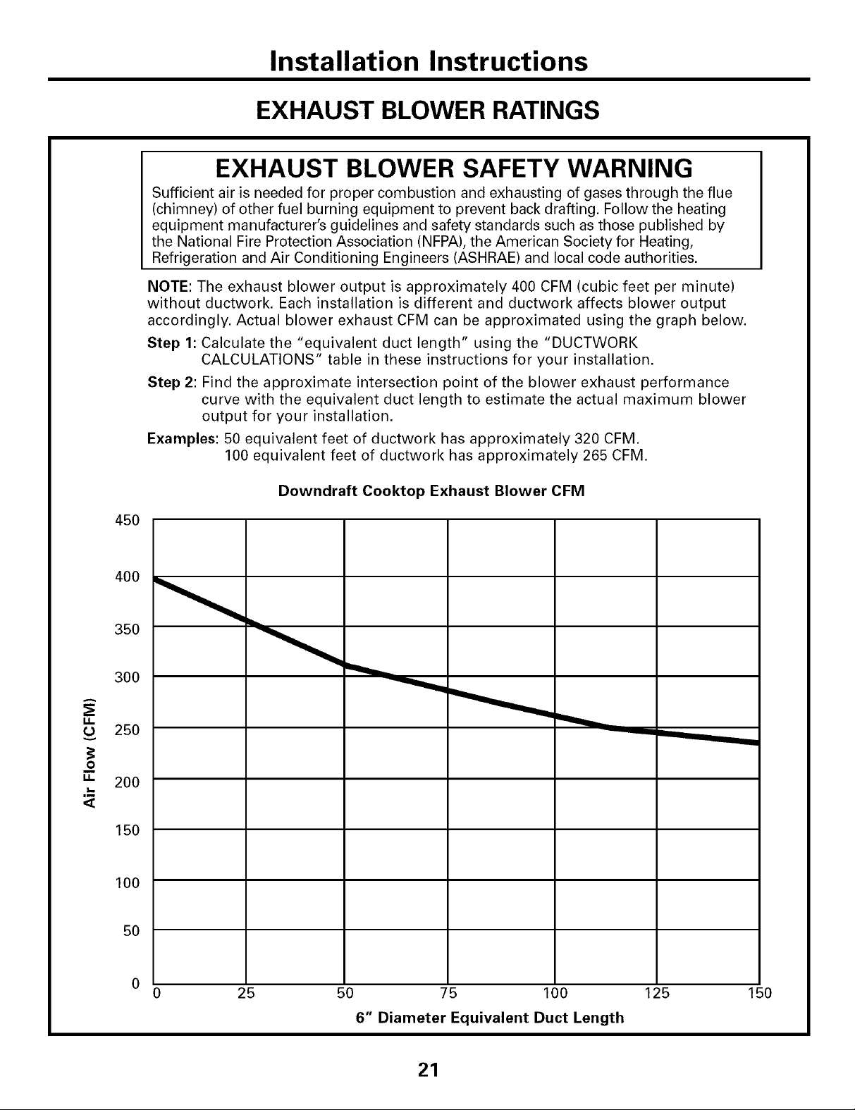
NOTE: The exhaust blower output is approximately 400 CFM (cubic feet per minute)
without ductwork. Each installation is different and ductwork affects blower output
accordingly. Actual blower exhaust CFM can be approximated using the graph below.
Step 1: Calculate the "equivalent duct length" using the "DUCTWORK
CALCULATIONS" table in these instructions for your installation.
Step 2: Find the approximate intersection point of the blower exhaust performance
curve with the equivalent duct length to estimate the actual maximum blower
output for your installation.
Examples: 50 equivalent feet of ductwork has approximately 320 CFM.
100 equivalent feet of ductwork has approximately 265 CFM.
g.
L)
g.
,m
<[
Downdraft Cooktop Exhaust Blower CFM
45O
350
300
25O
O
200
150
100
50
25 50 75 100 125
6" Diameter Equivalent Duct Length
21
150

Installation Instructions
DUCTWORK INSTALLATION
(Note: For planning purposes only.)
[] INSTALLING THE DUCTWORK
Use galvanized or aluminum duct in 6" round
or 31/4" x 10" size, or a combination of both.
PVC duct should be used if installing under a
poured concrete slab.
NOTE: Local building code must be followed
in specifying approved type and schedule of
ALL duct used.
Always use an appropriate roof or wall cap
with damper. Laundry-type wall caps should
NEVER be used.
Through Cabinet Toe Space Between Floor Joist
Downward Venting
Install ductwork, making male-female
connections in the direction of airflow as
shown. Secure all joints with sheet metal
screws and duct tape to assure an airtight
seal.
Duct Tape Over Seam
-- and Screw
OPTIONAL INSTALLATION:
REAR WALL VENTING
5" round duct may be used on SHORT DUCT
runs of 3 feet or less, such as direct to outside
wall venting.
\
4
nside Wall to Roof Direct to Outside
Rear Wall Venting
To convert blower exhaust direction, remove
four nuts behind the filter which hold blower
and wire finger guard.
Rotate blower and reinstall to vent chamber,
as shown above. Retighten nuts, but do not
overtighten.
Screw
Use the shortest and straightest duct run
possible. For satisfactory performance the
duct run should not exceed 100 feet
equivalent length. Refer to TABLE 1 of
equivalent lengths. Use TABLE 1 to calculate
the total equivalent length of the ductwork.
22

Installation Instructions
POWER SUPPLY LOCATIONS
GAS SUPPLY:
These cooktops are designed to operate on
natural gas at 4" of water column pressure
or on LP gas at 10" of water column
pressure.
• These cooktops are shipped from the
factory set for natural gas. If you decide to
use this cooktop with LP gas, conversion
adjustments must be made by a service
technician or other qualified person.
• The pressure regulator must be connected in
series with the manifold of the cooktop and
must remain in series with the supply line
regardless of type of gas being used.
For proper operation, the maximum inlet
pressure to the regulator must be no more
than 10" water column pressure for natural
gas and 14" water column pressure for LP
gas.
• When checking the regulator, the inlet
pressure must be at least 1" greater than the
regulator output setting. If the regulator is
set for 4" of water column pressure, the inlet
pressure must be at least 5". If the regulator
is set for 10" of water column pressure, the
inlet pressure must be at least 11". For ease
of installation, and if local codes permit, the
gas supply line into the cooktop should be
1/2" or 3/4" ID flexible metal appliance
connector, three to five feet long.
NOTE: Purchase a new flexible line. DO NOT
USE AN OLD PREVIOUSLY USED LINE.
• Make gas connection through rear wall, or
on cabinet floor at rear, as illustrated.
ELECTRICAL SUPPLY:
outlet 12"
above
cabinet floor
(mount on
side or back
cabinet wall
2" min. from
centerline)
4" (to clear toe kick area)
The built-in gas downdraft cooktop features
pilotless electric ignition for energy savings
and reliability. It operates on a 120-volt,
60-Hz power supply. A separate circuit,
protected by a 15-amp time-delay fuse
or circuit breaker, is required.
• A properly grounded 3-prong receptacle
should be located within reach of cooktop's
four foot power cord.
IMPORTANT: (Please read carefully.) FOR
PERSONAL SAFETY, THIS APPLIANCE MUST
BE PROPERLY GROUNDED,
The power cord of this appliance is
equipped with a three-prong (grounding)
plug which mates with a standard three-
prong grounding wall receptacle to minimize
the possibility of electric shock hazard from
this appliance. The customer should have
the wall receptacle and circuit checked by
a qualified electrician to make sure the
receptacle is properly grounded and
has correct polarity.
Where a standard two-prong wall
receptacle is encountered, it is the personal
responsibility and obligation of the customer
to have it replaced with a properly grounded
three-prong wall receptacle.
Do Not, Under Any Circumstances, Cut Or
Remove The Third (ground) Prong From The
Power Cord.
Do not use an extension cord.
23

Installation Instructions
UNPACKING THE COOKTOP/INSTALLING THE GASKET
[] INSTALLING THE FOAM GASKET
Do not install the cooktop into the countertop
without installing the foam gasket as shown.
It protects the bottom edge of the glass from
the countertop and seals the cooktop against
spills.
Remove the cooktop along with its shipping
pad from the shipping box. Remove the
shipping block from the downdraft vent
opening and place it under the shipping
pad to provide level support.
Center vent shipping block -
place under the shipping pad
to provide level support
CAUTION: GLASS IS FRAGILE.
DO NOT BUMP EDGE OF GLASS DURING
INSTALLATION.
Foam Gasket Installation Notes:
• The foam gasket tape should be installed
within 1/8" of the edge of the glass. Do not
stretch or twist the foam gasket tape.
CAUTION: Failure to install
foam gasket tape greatly increases the
potential of breaking the cooktop glass
when installing, especially in Corian ® or
granite countertops,
• Use care not to stretch the foam gasket tape
while it is installed or it will not stay in
place.
• Do not place foam gasket tape over the
metal flanges.
• Butt the foam gasket tape ends together at
each corner without overlapping.
• Trim the foam gasket tape to length without
stretching.
• Mitre cut outside corners of foam gasket
tape slightly if necessary for appearance.
Locate the foam gasket tape included with
your cooktop.
Peel off the white backing to install the foam
gasket tape on the bottom side of the cooktop
glass as shown.
Foam
Gasket
Tape
1X' max. to
Glass Edge
• Do not scratch the glass while cutting the
foam gasket tape.
24

Installation Instructions
INSTALLING THE COOKTOP
[] INSTALLING THE COOKTOP
CAUTION:
DO NOT LIFT
FROM
VENT OPENING.
Lift the cooktop by the glass side edges as
shown.
NOTE: Do not use the glass top vent opening
to lift or move the cooktop into position.
[] CHECKING FOR FLATNESS
Inspect the cooktop glass for rocking
or uneven gap on all four sides at the
countertop surface. Do not attempt to
force the glass to meet the countertop.
If the cooktop is perfectly flat with the
countertop surface, skip to Step 10.
If there is any rocking or an uneven gap,
then use a 1/4"nut driver to loosen the
eighteen (18) sheet metal screws on the
bottom panels of the cooktop while it is
still in the countertop.
Lower the cooktop into the countertop
opening, guiding it into position. Glass is
fragile--do not allow it to drop onto the
countertop. Support from the underside and
lower slowly.
Carefully remove your fingers one corner at a
time to lower the cooktop into position.
NOTE: Do not use Silicone RTV or caulk to
bond cooktop glass to countertop.
Loosen each bottom panel screw 1 or 2
turns. After all eighteen (18) screws are
loosened, recheck the cooktop for flatness
with the countertop surface.
Gently bump your hand along the outside
edge of the cooktop if needed to help it
settle evenly onto the countertop surface.
Retighten all eighteen (18) sheet metal
screws.
25

Installation Instructions
INSTALLING THE COOKTOP
[] INSTALLING THE HOLD-DOWN
RETAINERS
NOTE: Check for glass flatness in Step 9
before installing hold-down retainers.
appropriate for Hold-
countertop thickness retainer
Hold-down retainer
J
!
_i¸¸_I!!iii!!i!!¸_!;_!
Countertop
Thumb screw
Secure cooktop to the counter using the
hold-down retainers and thumb screws
shipped with the unit (one on each side,
or one on front and one on back).
/_
/
I-_ INSTALLING THE BLOWER TO
THE PLENUM
Orient the blower discharge opening to
match the ductwork in Steps 5 and 6. Slide
the four threaded studs on the side of the
blower housing into the four holes on the
side of the plenum.
NOTE: See Step 13 for installing the transition
duct to the blower, It may be easier to install
the transition duct to the blower before
installing the blower to the plenum.
down
[] INSTALLING THE BLOWER
PLENUM TO THE COOKTOP
Slide the plenum, with the blower opening on
the left, into the opening in the bottom of the
cooktop. Push up on the plenum until the
stops on the plenum contact the bottom of
the cooktop, and snap the plenum into place.
(You may have to move the plenum back and
forth to work it into place.)
Secure the plenum to the bottom of the
cooktop, on each side, using the four (4)
screws provided. Further secure the plenum
to the cooktop, from the top side, using the
two screws (2) provided.
From the vent opening in the top of the
cooktop, fasten the blower assembly securely
to the plenum with four (4) nuts,
4 Nuts
(7/16"
socket
126

Installation Instructions
INSTALLING THE COOKTOP
[] ATTACHING A BLOWER
TRANSITION DUCT
Use a blower transition duct for all downward
duct installations to connect to 6" round
standard ductwork. This 31/4" x 10" rectangle
to 6" round transition duct is available at
your local building supply store.
/ CreoV_he r
side)
Install the transition duct to the blower outlet.
Secure all joints with duct tape to assure an
airtight seal.
CONNECTING THE DUCTWORK
Connect the ductwork prepared in Steps 5 and
6 to the blower transition duct.
27

Installation Instructions
INSTALLING THE COOKTOP
[] INSTALL THE PRESSURE
REGULATOR
__ Regulator
Solid piping or
flexible connector
_ _------ Union
Solid piping
or flexible
Shut-off
va Ive
• Install the supplied pressure regulator in the gas line
as close to the cooktop inlet as possible. Allowances
for ventilation ducting may be necessary.
Make sure the regulator is installed in the right
direction.
• Install a manual shut-off valve in the gas line in an
easily accessible location.
NOTE: Instead of using solid piping to connect to
pressure regulator, an approved flexible metal
appliance connector may be used between the
shut-off valve and the pressure regulator, if local
codes permit.
Appropriate flare nuts and adapters are required at
each end of the flexible connector.
__ onnector
Pipe stub
TEST FOR LEAKS
INSTALL THE PRESSURE
REGULATOR (cont.)
IMPORTANT: Disconnect the cooktop and the
individual shut-off valve from the gas supply piping
system during any pressure testing of that system
at test pressures greater than 1/2 psig. Isolate the
cooktop from the gas supply piping system by
closing the individual manual shut-off valve to the
cooktop during any pressure testing of the gas
supply piping system at test pressures equal to or
less than 1/2 psig.
[] BLOWER ELECTRICAL
CONNECTIONS
• Loosen the two screws and remove and discard the
sheet metal connector cover on the cooktop bottom.
Save the screws for reinstallation later.
• Connect the 5-pin plug on the blower assembly to
the matching 5-pin receptacle on the bottom of the
cooktop.
\
5-pin
connectors
WARNING:Do NOT USE A FLAME TO CHECK
FOR GAS LEAKS! Do not use the cooktop until all
connections have been leak tested.
Perform leak test per the following instructions:
1.Purchase a liquid leak detector or prepare a soap
solution of one part water, one part liquid detergent.
2.When all connections have been made, make sure
all cooktop controls are turned to OFF and turn the
gas supply valve to ON.
3.Applythe liquid leak detector or the soap solution
around all connections from the shut-off valve to the
cooktop.
4.A leak is identified by a flow of bubbles from the
area of the leak.
5.If a leak is detected, turn the gas supply off. -lighten
the fitting. Turn the gas on and test again.
If the leak persists, turn the gas supply off and
contact your dealer for assistance. Do not attempt to
operate the cooktop if a leak is present.
Fold all wires into the electrical enclosure. Secure
the enclosure with the screws removed earlier,
making sure that no wires are trapped.
• Plug the cooktop cord set into a suitable electrical
outlet. See step 17.
28
f
"_5-pin
connectors
--Electrical
enclosure
_t
Flexible

Installation Instructions
ELECTRICAL CONNECTIONS
[] ELECTRICAL REQUIREMENTS
120-volt, 60-Hertz, properly grounded branch
circuit protected by a 15-amp or 20-amp circuit
breaker or time-delay fuse.
EXTENSION CORD CAUTIONS
Because of potential safety hazards associated
with certain conditions, we strongly recommend
against the use of an extension cord. However, if
you still elect to use an extension cord, it is
absolutely necessary that it be a UL-listed, 3-wire
grounding-type appliance extension cord and
that the current carrying rating of the cord in
amperes be equivalent to, or greater than, the
branch circuit rating.
GROUNDING
IMPORTANT m (Please read carefully.)
FOR PERSONAL SAFETY, THIS APPLIANCE
MUST BE PROPERLY GROUNDED.
Preferred Method
An adapter may be used only on a
15-amp circuit. Do not use an adapter on
a 20-amp circuit. Where local codes permit,
a TEMPORARY CONNECTION may be made
to a properly grounded two-prong wall
receptacle by the use of a UL-listed adapter,
available at most hardware stores. The larger
slot in the adapter must be aligned with the
larger slot in the wall receptacle to provide
proper polarity in the connection of the
power cord.
Temporary Method
(Adapter plugs not permitted in
Canada)
Align large prongs/slots
Ensure proper
ground and
firm connection
before use
Ensure proper ground
exists before use
The power cord of this appliance is equipped
with a three-prong (grounding) plug which
mates with a standard three-prong grounding
wall receptacle to minimize the possibility of
electric shock hazard from this appliance.
The customer should have the wall receptacle
and circuit checked by a qualified electrician to
make sure the receptacle is properly grounded.
Where a standard two-prong wall receptacle is
encountered, it is the personal responsibility and
obligation of the customer to have it replaced
with a properly grounded three-prong wall
receptacle.
DO NOT, UNDER ANY CIRCUMSTANCES,
CUT OR REMOVE THE THIRD (GROUND)
PRONG FROM THE POWER CORD.
-&CAUTION: Attaching the adapter
ground terminal to the wall receptacle
cover screw does not ground the
appliance unless the cover screw is metal,
not insulated, and the wall receptacle is
grounded through the house wiring, The
customer should have the circuit checked
by a qualified electrician to make sure the
receptacle is properly grounded.
When disconnecting the power cord from the
adapter, always hold the adapter with one
hand. If this is not done, the adapter ground
terminal is very likely to break with repeated
use. Should this happen, DO NOT USE the
appliance until a proper ground has again
been established.
29

Installation Instructions
FINAL ASSEMBLY
[] ASSEMBLE BURNERS,
CHECK IGNITION
Assemble burner as shown.
Ora
//_'-//,= Curved side
/__l _ toward the
_# !f _1 _4 center
@ Burner cap
rode
_//_ec/t _ Burner head
CAUTION:Do not operate the burner without
all burner parts in place.
Medium _o-_
Head ""_
and Cap _ B
Medium
Head ---%_
and Cap (_ B
eB A= AO Small
eB c • __"_Large
Front of Cooktop c
Burner base
Head
and Cap
Head
and Cap
INSTALLDOWNDRAFT FILTER,
VENT GASKETAND VENT GRILLE
Do not operate the vent without the filter in place.
• Place the filter diagonally through the vent
opening.
Vent Filter
Vent
-Chamber
• Make sure it rests, at an angle, on the supports in
the vent opening.
Place the burner heads on the burner bases
matching the letters. Place the caps on the heads.
Make sure that the heads and caps are placed on the
correct size burner. The
burner heads and burner
bases are labeled A, B and
C to aid reassembly. There
is one small (A), two
medium (B) and one large
(C) head and cap.
Make sure the notch in the burner head is positioned
toward the electrode. Rotate the burner head around
the burner base until it is level and securely seated.
Place the grates over the burners.
Check for proper ignition:
• Push in one control knob and turn to LITE position.
• The igniter will spark and the burner will light; the
igniter will cease sparking when the burner is lit.
• First test may require some time, while air is
flushed out of the gas line.
• Turn knob to OFF.
• Repeat the procedure for each burner.
• Fit the vent grille gasket around the edge of the
downdraft vent opening. Make sure the front of the
gasket is installed toward the front of the cooktop.
• Carefully place the vent grille onto the gasket on
the downdraft opening.
G rille,_-_ Vent Grille
et
CHECK OPERATION OF DOWNDRAFT
• Turn the vent fan speed control to HI, MED and
LO to make sure all speeds operate correctly.
'30
Before YouCallForService...
Troubleshooting -tips
Save time and money! Review the chart on this page
first and you may not need to carl for service.
GEAppliances.com
Possible Causes
Waterwon'tboil
What To Do
• Cover pan with a lid.
• Turn the downdrafl tim OFF until the water begins
to boil.
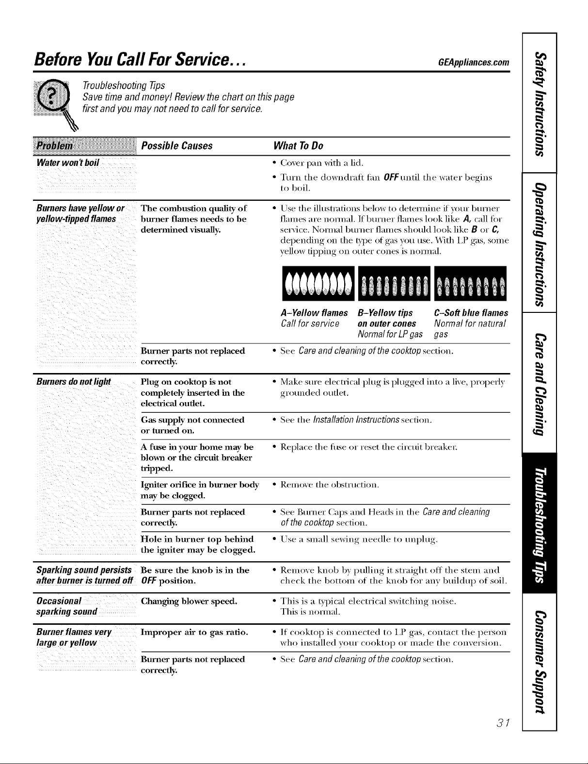
Burners have yellow or
yellow-tipped flames
The combustion quality of
burner flames needs to be
determined visually.
• Use tile illustrations below to detemfine if yore" bm'ner
flames are nomml. If bm'ner flames look like A, call fin"
service. Nornlal burner flalnes should look like B or C.
depelMing on tile ITpe ot gas you use. X._]th I.P gas, some
yellow tipping on outer cones is nomml.
A-Yellow flames B-Yellow tips C-Soft blue flames
Callfor service on outercones Normal for natural
NormalforLPgas gas
Burner pm'ts not replaced • See Careand cleaningof thecooktopsection.
correctly.
Burners do notlight Plug on cooktop is not • Make sure electrical l)blg, is l)lugged,, into a lixe, properl)
completely h_serted ha the groulMed outlet.
electrical outlet.
Gas supply not comaected • See the Installation Instructions section.
or turned on.
A fuse in your home may be • Replace tile fllse or reset tile circuit breakei:
blown or the circuit breaker
tripped.
Igniter orifice ha burner body " Remoxe tile obstruction.
may be clogged.
Burner paxts not replaced • See gm'ner (_aps and Headsin the Careand cleaning
correctly, ofthecooktop section.
Hole in burner top behind • Lrse a slnall ,sewino_ needle to unl)lu_,
the i_fiter may be clogged.
Sparking sound persists Be sure the knob is in the • Reulo_e knob b) I)ullin°_ it straight off tile stein and
after burner is turned off OFFposition, check tile bottoln of tile knob for _lIl} buildu I) of soil.
Occasional Chmaghag blower speed. " This is a t}pical electrical switching noise.
sparking sound This is nomml.
Burner flames very huproper air to gas ratio. • If cooktop is connected to 12 gas, contact tile person
large oryellow who installed your cooktop or inade tile con'_ersion.
Bunaer paxts not replaced " See Care and cleaning ofthe cooktopsection.
correctly.
31

Before YouCall ForService...
Troubleshooting -tips
Possible Causes
Controlknobs
Controls improperly set. To turn fi'om the OFF position, push the knob in
will notturn
Fan does not work The fan control knob is • Turn knob in clockwise direction to turn tim on.
improperly set.
Cord improperly cmmected • Check c(muecti(ms. Turn (>n l)ower at tile fl/se box.
or power turned off.
Poor venting Clogged filter. • Clean filter per instructions.
House too airtight. • Open a window slightly to in'oxide fresh air source.
Wall cap obstructed. • Remove blockage fl'om exterior wall Cal).
Wall cap damper door stuck. • Check eXtelJOl _wall cap (lmnl_er door fi)r fl'ee movement
Duct length exceeds • Reduce Ut/lllbeI" of elbows to siInplit_' duct l't/u.
recommended 100
equivalent foot maximum.
Scratches (mayappear Incorrect clemfii_g * Scratches are not removable. Tiny scratches will become
as cracks) on cooktop methods being used. less visible in tim e as a result of cleaning.
glass surface
Cookware with rough bottoms * To avoid scratches, t/se the i'eCOlHllleuded cleauiug
being used or coarse particles procedures. Make St/l'e bottoIilS of cookwm'e are clean
(salt or sand) were between befi)re rise, aud t/se cookwaYe with smooth bottoms.
the cookware and the surface
of the cooktop.
Cookware has been slid
across the cooktop surface.
What To Do
and then ttu'n. The knob can only be ttu'ned in a
counterclockwise direction. _*Vhen the knob is at any
other position, it can be turned in either direction
without being pushed in.
01" ()bstll/ctiou,
Areas of discoloration Food spillovers not cleaned * See tile Cleaningthe glass cooktop section.
on the cooktop before next use.
Hot surface on a model • This is normal. Tile surface may appear discolored
with a light colored cooktop, when it is hot. This is teml)oraI T and will disappear
as the glass cools.
Plastic melted to Hot cooktop came into • See tile Glass surface--potential for permanent damage
the surface contact with plastic placed sectiou in the Cleaning the glass cooktop sectiou.
on the hot cooktop.
Pitting (or indentation) Hot sugar mixture spilled * Call a qualified technician for replacement.
of the cooktop on the cooktop.
32

GE Service Protection Plus rM
GE, a name recognized worldwide _br quality and dependability; oflers y'ou
Service Protection Plus'"--comprehensive protection on all y'our appliances--
No Matter What Brand!
Benefits Include:
• Backed by GE
• All brands covered
• Unlimited service cars
• All parts and labor costs included
• No out-of-pocket expenses
• No hidden deductibles
• One 800 number to call
You will be c()mpletel,_ satisfied with our serxice protection or you may request }our inonev back
on tile remaining xalue of _o/u" contract. No questions asked. It's that simple.
Protect vom" refl_igerat(m dishwasher; washer and (hTe_; range, TV, VCR and much more--any brmad!
Plus there's iso extra charge tot eulergency ser;'ice and low monthly financing is available. Even icemaker
coverage and tood spoilage protection is offered. You can rest eas> knowing that all vom" valuable
household products are protected against expensive repairs.
Place your confidence in (;E and call us in tile Ij.S. toll-free at _tlU._)Z_).ZZZ/-]:
for inoi'e infoi'u/ation,
*-M1lmmds cov<_<d, up Io 20 ?'<a_ old, in Ih< <onlinental U.S.
We71CoverAnyAppliance.
Anywhere. Anytime.*
__ _C/_ll'h__2e............
Please place in envelope and mail to:
General Electric Company
Warranty Registration Department
EO. Box 32150
Louisville, KY 40232-2150
33

Consumer Product Ownership Registration
Dear Customer:
Thank you for purchasing our product and thank you for placing your confidence in us.
_A/eare proud to ha_e you as a customer!
Follow these three steps to protect your
Important: If you did not get a registration card with your
................................................................................................... _,,,._ (MI h(r(
new appliance investment:
Complete mid mail
your Constuner
Product Owuership
Registration today.
t]a_e the t)eace o/
mind of knowing we
c_ln contact you ill
th( unlikely (v(nt of
a sa/(q_ modification.
AJler mailing tile
registration below,
store this do( ument
in a sa/(' pla_ c. It
contains intormation
you will need should
you require scrvi(e.
Our scrvi_ e nmnber is
800.GE.(2\RES
(800.432.2737).
Model Number Serial Number
, , , , , I I , , , , , , , I
product, detach and return the form below to
ensure that your product is registered, or register
online at GEAppliances.com.
[_ca(t VO/IF Owl/er's
Mamml carefully.
It will hel t) you
ot)era|e your new
at)t)liame t)rot)erly.
Consumer Product Ownership Registration
Serial Number
I,,,,,, , , , , , I
MI: [ Ms. M*_. Mixs
Fir_,l I I L_Sl]
Name I I I I I I I I I Nain(! I I I I I I I I I I I I
_11-( (!1 I
Addr,. ss I I I I I I I I I I I I I I I I I I I I I I I I
, , , , , , , I E-mailAddress*
1Hw Placed
Monlh
' F'l(ase provide your (>mail address Io r( ceiv(, via c-mail, discounts, sp(cial off(rs and olh(r important
communi(ations from (;E Applian((s ((;ILk).
Ch((k h(r( if you do 11ol Wallt to F(_(( iv(! ( olnmtmi(ations trom GEA's ( arefully sel( (led partners.
GEAppfiances
GEConsumerProducts
GenerM E/outfit Company
Louisvi/Io,Kentucky
_Z_ www.GEAppliances.com
Model Number
I I I I I I i
Zip I

GEGasCooktopWarranty.
All warranty service provided by our Factory Service Centers,
or an authorized Customer Care®technician. To schedule service,
on-line, 24hours a day, vis# us at GEAppfiances.com,
or call 800.GE.CARES (800.432.2737).
Staple your receipt here.
Proof of the original purchase
date is needed to obtain service
under the warran_
GEWill Replace:
Anypattot the cooktop which tifils due to a detect in materials or workmanship, During this
From the date of the full one-year warranty, (;E will also pro_ide, free of charge,all lab(n" and in-ham e sei_,ice to
origina!purchase replace the defecti, e part.
A replacement glass cooktop if it should crack or (liscolox: During this limited additional
From the date of the four-year warranty, _ou will be responsible tar anx labor or in-home service to replace
originalpurchase the defecdxe part,
Service trips to your home to teach you how to use
the product.
hnproper h_staJlation, delivery or maintenance.
Failure of the product if it is abused, misused, or used
for other thml the intended purpose or used
commercially.
Dmnage to the glass cooktop caused hy the use of
demlers other thm_ the recommended clemlhlg cretans
mid pads.
Replacement of house fuses or resetting of circuit
breakers.
Damage to the product caused by accident, f'tre, floods
or acts of God.
h_cidentaJ or consequentiaJ damage caused by possible
defects with this applimlce.
Dmnage caused after delivery.
Dmnage to the glass cooktop caused by hardened
spills of sugaxy materials or melted plastic that are
not clemled according to the dJrectim_ in the
Owner's MmmaJ.
This warranty is extended to the original purchaser and any succeeding owner for products purchased for
home use within the USA. In Alaska, the warranty excludes the cost of shipping or service calls to your home.
Some states do not aflow the exclusion or limitation of incidental or consequential damages. This warranty
gives you specific legal rights, and you may also have other rights which vary from state to state. To know
what your legal rights are, consult your local or state consumer affairs office or your state's Attorney General
Warrantor." General Electric Company.Louisville, KY40225
35

ConsumerSupport.
GEAppliancesWebsite GEAppliances.com
Have a question or need assistance with your appliance? Try the GE Appliances Website 24 hotu_ a day,
any day of the year! For greater convenience and faster selMce, you can now download Owner's Manuals,
order parts, cat;dogs, or even schedule service ondine. You can also '%sk Our Team of EN)erts ......
yotlr qtlestions, and so lI/rich lI/ore...
ScheduleService
Expert (;E repair sels:ice is onlx one step away fl'om your dooi; Get on-line and schedule vc,ur service at
your conxenience 24 hom_ am (lm of the '_ear! Or call 800.GE.(_AI_ES (800.432.2737) dining n(mnal
business hom_.
GEAppliances.com
RealLifeDesignStudio GEAppliances.com
GE supports the/!ni\'ei_al Design concept--products, services and environments that can be used by
people ot all ages, sizes and capabilities. _,\'e recognize the need to design fi)r a wide range of i)hysical and
mental abilities and impaim_ents. For details of GE's Univei_al Design applications, including kitchen
design ideas fin" people with disabilities, check out our _,Vebsim today. For the hearing impaired, please call
800.TDD.GEAC (800.833.4322).
Extended Warranties GEAppliances.com
Purchase a (;E extended warrant_ and learn about special discounts that are a_ailable while )our warranty
is still in effect. YOtl can purchase it on-line an)time, or call 800.626.2224 during nomml business horus.
(;E (_onsulner Home Serxices will still be there after )our warrant), expires.
PartsandAccessories GEAppliances.com
Individuals qualified to seI_'ice their own appliances can have parts or accessories sent directly to their
homes (VISA, MasterCard and Discover cards are accepted). Order on-line today, 24 hom_ evela' day or
by phone at 800.626.2002 during nomml business hom_.
Instructions contained in thismanual coverprocedures tobe performed by any user. Other servicing generally
should be referred to qualified service personnel Caution must be exercised, since improper servicing may cause
unsafe operation.
ContactUs GEAppliances.com
If you are not satisfied with the service you receive from GE, contact us on our _'ebsite with all the details
including your phone ntlIllbeI; oI" wlite to: General Managei; Customer Relations
GE Appliances, Appliance Park
I,ouisville, KY 40225
RegisterYourAppliance GEAppliances.com
Register your new appliance on-lhae--at your convenience! Timely, I)r°(luct registration, will allow for
enhanced communication and prompt service under the temps of your warranty, should the need arise.
You mm also mail in the pre-printed registration card included in the I)ackin'"_ material.
Printed in flTeUnited States
 Loading...