

Page 1
Questions? Call 800.GE.CARES (800.432.2737) or Visit our Website at: www.GEAppliances.com
LP Conversion Gas Cooktop
Instructions
JGP985
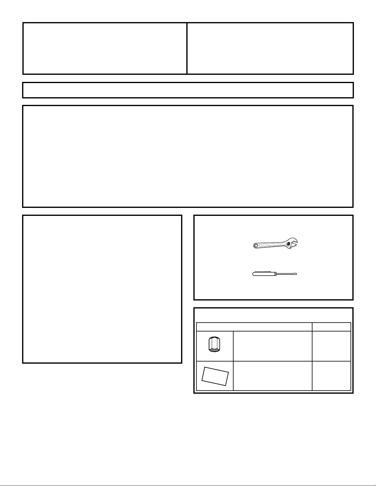
Adjustable wrench
PART QUANTITY
Brass orifices 4
Stick-on conversion label 1
Small, thin-blade flat screwdriver with approximately 1/8″
blade width is needed to access the calibration screw.
49-80298
4226-0018-00
01-05 JR
Printed in Korea
1
BEFORE YOU BEGIN
Read these instructions completely and carefully.
•
IMPORTANT – Save these instructions for
local inspector’s use.
•
IMPORTANT – Observe all governing codes
and ordinances.
• Note to Installer – Be sure to leave these instructions
with the Consumer.
• Note to Consumer – Keep these instructions
for future reference.
• This cooktop is factory set for natural gas operation.
Conversion to LP operation should be performed by a
qualified technician or installer. Keep these instructions
for future reference. When converting to LP, save the
original parts for possible future use.
• Product failure due to improper installation is not covered
under the GE Appliance Warranty.
FOR YOUR SAFETY
WARNING – If you are using LP (bottled) gas,
all adjustments described in the following steps must be
made before attempting burner adjustments or use of the
cooktop.
WARNING – This conversion kit shall be
installed by a qualified service agency in accordance with
the manufacturer’s instructions and all applicable codes
and requirements of the authority having jurisdiction.
If the information in these instructions is not followed
exactly, a fire, explosion or production of carbon
monoxide may result, causing property damage, personal
injury or loss of life. The qualified service agency is
responsible for the proper installation of this kit. The
installation is not proper and complete until the operation
of the converted appliance is checked as specified in the
manufacturer’s instructions supplied with the kit.
TOOLS YOU WILL NEED
PARTS INCLUDED
Page 2
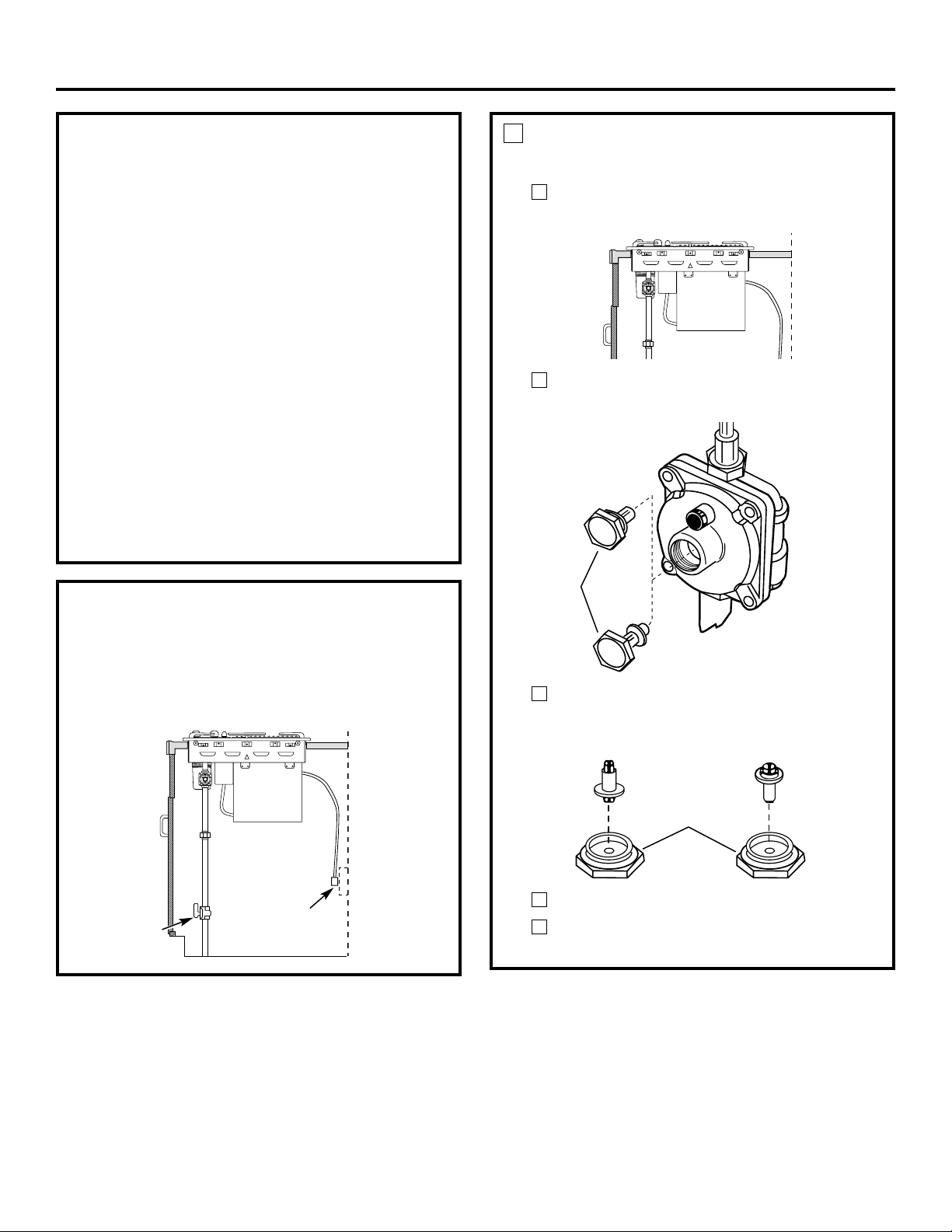
CONVERT THE PRESSURE REGULATOR
Locate the pressure regulator under the front of
the cooktop.
Remove the nut from the pressure regulator with
an adjustable wrench.
Remove the plastic pin from the inside of the
nut, turn the pin 180° and snap the pin back
into the nut.
Re-install the nut onto the regulator.
Apply the LP Conversion label next to the
Rating Plate.
E
D
C
B
A
1
2
LP Conversion Instructions
Nut
Natural gas
LP gas
Nut
Natural gas LP gas
GAS SUPPLY
• With the installation of this conversion kit, the cooktop
should operate on LP gas at 10″ of water column
pressure.
• The pressure regulator must be connected in series
with the manifold of the cooktop and must remain in
series with the supply line. For proper operation, the
maximum inlet pressure to the regulator must be no
more than 14″ water column pressure for LP gas.
• When checking the regulator, the inlet pressure must
be at least 1″ greater than the regulator output setting.
If the regulator is set for 10″ of water column pressure,
the inlet pressure must be at least 11.″
IMPORTANT – Disconnect the cooktop
and the individual shut-off valve from the gas supply piping
system during any pressure testing of that system at test
pressures greater than 1/2 psig. Isolate the cooktop from
the gas supply piping system by closing the individual
manual shut-off valve to the cooktop during any pressure
testing of the gas supply piping system at test pressures
equal to or greater than 1/2 psig.
TURN OFF GAS AND ELECTRIC SUPPLY
BEFORE YOU BEGIN, TURN OFF THE GAS SUPPLY
AT THE SHUT-OFF VALVE. DISCONNECT THE
ELECTRICAL SUPPLY FROM THE COOKTOP.
Shut-off valve
Electrical supply
Page 3

CHECK IGNITION
Connect electrical supply cord.
Turn on the gas; check for leaks using a liquid leak
detector at all joints in the system.
WARNING: DO NOT USE A FLAME
TO CHECK FOR GAS LEAKS.
Push in one control knob and
turn to the LITE position. The
igniter will spark and the burner
will light. The first test may
require some time while air is
flushed out of the gas line. After
ignition, turn the control knob to
the HI position and wait until the flame settles.
Check to determine if your burner flames are
normal. If burner flames look like A, turn off the
burner and make sure all parts are assembled
correctly. Reassemble and check.
Normal burner flames should look like B or C,
depending on the type of gas you use. With LP gas,
some yellow tipping on outer cones is normal.
Turn the knob to OFF.
Repeat the procedure for each burner.
E
D
C
B
A
4
ADJUST GRILL BURNER AIR SHUTTER
The air shutters for the grill burner may need to
be adjusted to get better flame appearance and
ignition. The air shutters for the grill burner are
located on the bottom of the grill burner. To access
the air shutters, remove the grill grate, and then the
grill burner. Slide air shutter backward or forward
to increase or decrease the size of the air opening.
Air shutters fit snugly on the grill burner, so a
screwdriver blade may be required to make this
adjustment (see illustration). The snug fit of the air
shutter assures it will remain positioned correctly.
3
CONVERT SURFACE BURNERS
Remove all grates and burner modules.
With an adjustable wrench or an open end
wrench, remove the brass orifices.
Find the inscribed LP orifices in the holder in the
front of the electric cover beneath the cooktop.
Install the inscribed LP orifices in place of the
natural gas orifices.
Replace the burner modules and grates.
Keep all the spuds with your cooktop so you have
them if you move or get a different gas hook-up.
F
E
D
C
B
A
2
3
LP (Propane) Gas 10″ W. C . P.
Burner Output Rating in BTU/HR
Location BTUs Orifice Size Engraving
Left Rear (LR) 9,100 .0354 LP
Left Front (LF) 9,100 .0354 LP
Right Rear (RR) 9,100 .0354 LP
Right Front (RF) 9,100 .0354 LP
Turn counterclockwise to remove
Orifice
Turn clockwise to tighten
Air shutter
Insert screwdriver blade in
slot and twist with slight
pressure to allow air shutter
to slide easily
A–Yellow flames
Not normal;
check alignments
B–Yellow tips
Normal for
LP gas
C–Soft blue flames
Normal for
natural gas
LP Conversion Instructions
Page 4

CONVERTING BACK TO NATURAL GAS
To convert the cooktop back to natural gas, reverse
the steps taken to convert to LP.
Once the conversion is complete and checked OK,
fill out the LP sticker and include your name,
organization and date conversion was made. Apply
the sticker near the cooktop gas inlet opening to
alert others in the future that this appliance has been
converted to LP gas. If converting back to natural gas
from LP, please remove the sticker so others know
the appliance is set to use natural gas.
NOTE: For operation at elevations above 5000 ft.
(1500 m), equipment ratings shall be reduced at a
rate of 2% for each 1000 ft. (300 m) above sea level
before selecting appropriately sized equipment, i.e.:
Use smaller orifices.
6
ADJUST THE LOW FLAME (SIMMER) SETTING
The top burner valves have low flame/simmer
adjustment screws accessible through the valve
switches. A flashlight may be needed to locate the
screw. A small, thin-blade screwdriver (approximately
1/8″ blade width) is needed to access the screw.
Light two other burners and set the knobs to
a medium to high setting.
Light the burner to be adjusted and turn the knob
to LOW.
To make adjustment, remove the control knobs.
Insert a screwdriver through the access hole in
the valve switch. Engage the adjustment screw
in the valve.
If the flames were
too small or fluttered,
open the valve more
than the original setting.
If the flames are too
large, close the valve
more than the original
setting.
Make the adjustment by slowly turning the screw
until the flame appearance is correct. For the left
side, install the grill burner for the adjustment.
The left side cannot be turned down as low as the
right side if the grill burner is to be used.
Adjust the low flame setting using the valve bypass
screw as follows:
Low setting adjustments must be made with two
other burners in operation on a medium setting.
This prevents the low flame from being set too low,
resulting in the flame being extinguished when
other burners are turned on.
Testing Flame Stability:
Test 1: Turn the knob from HI to LOW quickly.
If the LOW flame goes out, increase the
flame size and test again.
Test 2: With the burner on the LOW setting,
open and close the cabinet door under the
cooktop. If the flame is extinguished by the
air currents created by the door movement,
increase the flame height and test again.
Test 3: With the burner on the LOW setting, turn
the downdraft vent fan to the HI position.
If the flame is extinguished by the air
currents created by the downdraft vent fan,
increase the flame size and test again.
E
D
C
B
A
5
4
Natural Gas 5″ W. C . P.
Burner Output Rating in BTU/HR
Location BTUs Orifice Size Engraving
Left Rear (LR) 10,000 .0550 NAT
Left Front (LF) 10,000 .0550 NAT
Right Rear (RR) 10,000 .0550 NAT
Right Front (RF) 10,000 .0550 NAT
LP Conversion Instructions
ADJUST THE LOW FLAME
(SIMMER) SETTING
(cont.)
Flame Recheck:
Repeat the adjustment for each burner. After the
adjustment is made, turn all burners off. Ignite
each burner individually. Observe the flame at the
HI position. Rotate the valve to the LOW position
and be sure that the flame size decreases as the
valve is rotated counterclockwise.
F
5
 Loading...