

Page 1
1
TOOLS YOU WILL NEED
MATERIALS YOU MAY NEED
229C4053P522-2
31-10539-2 05-03 JR
Questions? Call 800.GE.CARES (800.432.2737) or Visit our Website at: www.GEAppliances.com
In Canada, call 1.800.361.3400 or Visit our Website at: www.geappliances.ca
Installation
36″ Sealed Gas Cooktop
Instructions JGP628, JGP962, JGP963, ZGU36
BEFORE YOU BEGIN
Read these instructions completely
and carefully.
•
IMPORTANT
— Save these
instructions for local inspector’s use.
•
IMPORTANT
— Observe all
governing codes and ordinances.
• Note to Installer – Be sure to leave these
instructions with the Consumer.
• Note to Consumer – Keep these
instructions for future reference.
• Product failure due to improper installation
is not covered under the Warranty.
WARNING — This appliance must
be properly grounded.
•
IMPORTANT — Leak testing of the
appliance shall be conducted according to
the manufacturer’s instructions.
• Proper installation is the responsibility
of the installer and product failure due to
improper installation is NOT covered under
warranty.
IN THE COMMONWEALTH OF
MASSACHUSETTS:
• This product must be installed by a
licensed plumber or gas fitter.
• When using ball-type gas shut-off valves,
they shall be the T-handle type.
• A flexible gas connector, when used, must
not exceed 3 feet.
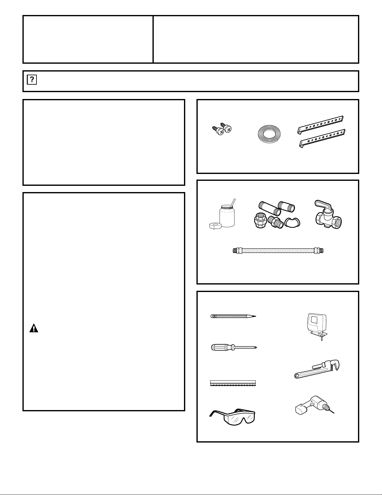
PARTS INCLUDED
2 Hold
Down Brackets
Shut Off Valve
Pipe Fittings
CSA-Approved Flexible Gas Line
3/8″ Min. ID, 1/2″ NPT Connection,
3-foot Maximum Length (Massachusetts Only)
Joint Sealant
Saber Saw
Pencil
Safety Glasses
1/8″ Drill Bit & Electric
or Hand Drill
Ruler or Straightedge
Foam Tape
(Glass Top
Models Only)
2 Screws
Phillips Head
Screwdriver
Pipe Wrench
Page 2
2
Installation Instructions
FOR YOUR SAFETY:
WARNING — If the information
in this manual is not followed exactly, a fire,
explosion or gas leak may result causing
property damage, personal injury or death.
Do not store or use gasoline or other
flammable vapors and liquids in the vicinity
of this or any other appliance!
WHAT TO DO IF YOU
SMELL GAS:
• Do not try to light any appliance. Do not
touch any electrical switch; do not use any
phone in your building.
• Immediately call your gas supplier from a
neighbor’s phone. Follow the gas supplier’s
instructions.
• If you cannot reach your gas supplier, call
the fire department.
Installation and service must be performed by
a qualified installer, service agency or the gas
supplier.
IMPORTANT SAFETY INSTRUCTIONS
This cooktop has been design certified by
UNDERWRITERS LABORATORIES and CSA
International. You’ll find safety precautions in
your Owner’s Manual. Read them carefully.
• Installation of this cooktop must conform
with local codes or, in the absence of local
codes with the National Fuel Gas Code,
ANSI Z223.1–Latest edition.
• Be sure your cooktop is installed properly
by a qualified installer or service technician.
• To eliminate reaching over surface burners,
cabinet storage above burner should be
avoided.
• Do not install the unit near an outside door
or where a draft may affect its use.
ELECTRICAL REQUIREMENTS
This appliance must be supplied with the
proper voltage and frequency and connected
to an individual, properly grounded branch
circuit, protected by a circuit breaker or fuse
having amperage as noted on the rating plate.
We recommend you have the electrical wiring
and hookup of your cooktop connected by a
qualified electrician. After installation, have
the electrician show you where your main
cooktop disconnect is located.
Check with your local utilities for electrical
codes which apply in your area. Failure to
wire your cooktop according to governing
codes could result in a hazardous condition.
If there are no codes, your cooktop must be
wired and fused to meet the requirements of
the National Electrical Code, ANSI/NFPA No.
70—Latest edition. You can get a copy by
writing:
National Fire Protection Association
Batterymarch Park
Quincy, MA 02269
In Canada your cooktop must be wired
and fused to meet the requirements of
the Canadian Electrical Code.
Be sure the installation of this product
in a mobile home conforms with the
Manufactured Home Construction and
Safety Standard, Title 24 CFR, Part 3280.
If this standard does not apply, you must
follow the standard for Manufactured Home
Installations, ANSI A225.1 and Manufactured
Home Installations, Sites and Communities
and ANSI/NFPA 501A or with local codes.
You can get a copy of the Federal Standard
by Writing:
Office of Mobile Home Standards
HUD Building
451 7th Street, S.W.
Washington, D.C. 24010
Page 3
3
Installation Instructions
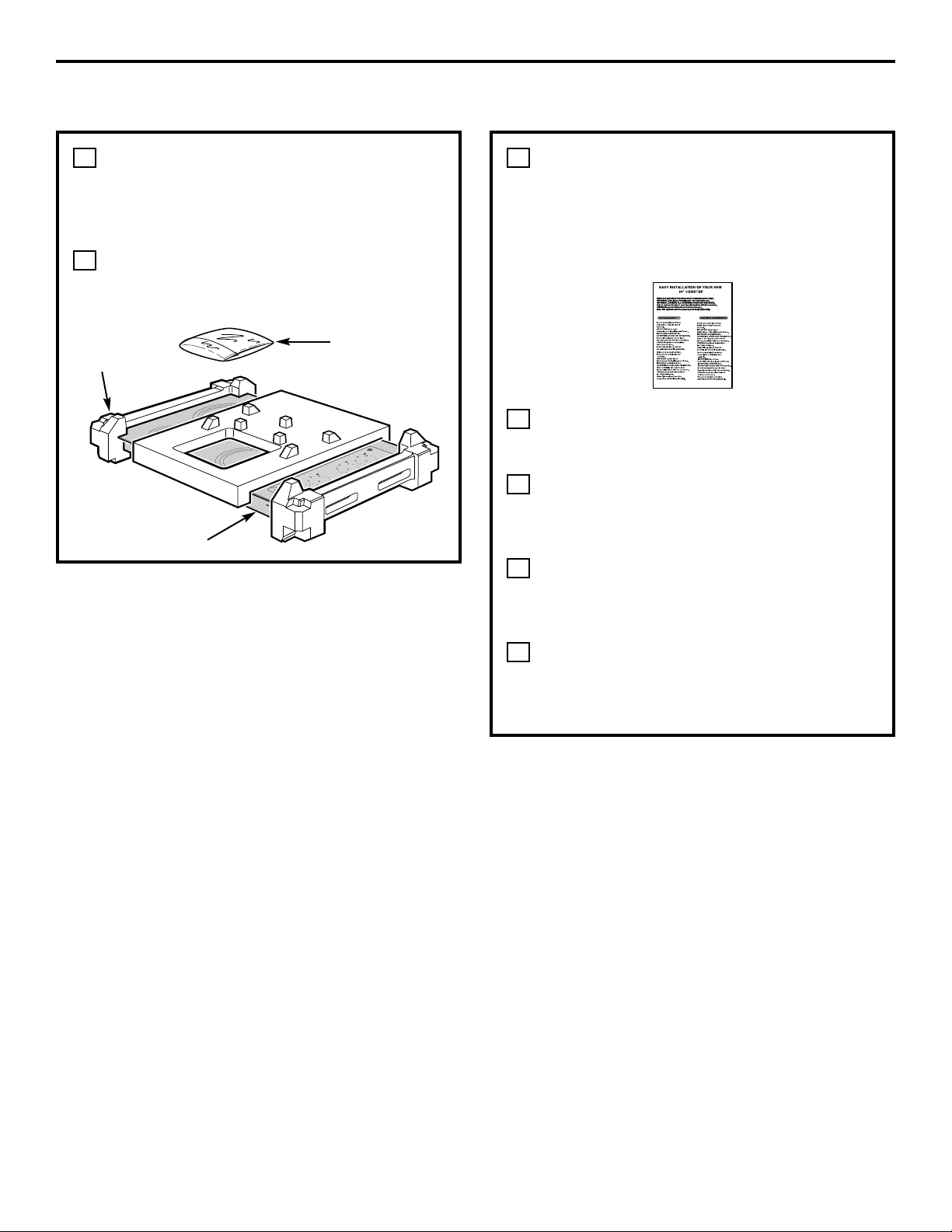
When preparing cooktop opening,
make sure the inside of the cabinet and
the cooktop do not interfere with each
other. (See section on preparing the
opening.)
Remove packaging materials and
literature package from the cooktop
before beginning installation.
B
A
PRE-INSTALLATION CHECKLIST
Remove Installation Instructions from
literature pack and read them carefully
before you begin.
Be sure to place all literature, Use and
Care, Installations, etc. in a safe place
for future reference.
Make sure you have all the tools and
materials you need before starting the
installation of the cooktop.
Your home must provide the adequate
electrical service needed to safely and
properly use your cooktop. (Refer to
section on electrical requirements.)
When installing your cooktop in your
home, make sure all local codes and
ordinances are followed exactly as
stated.
Make sure the wall coverings,
countertop and cabinets around the
cooktop can withstand heat (up to
200°F) generated by the cooktop.
G
F
E
D
C
Literature Package
Styrofoam
Packaging
Cooktop
O
H
O
T
N
Page 4
4
Installation Instructions
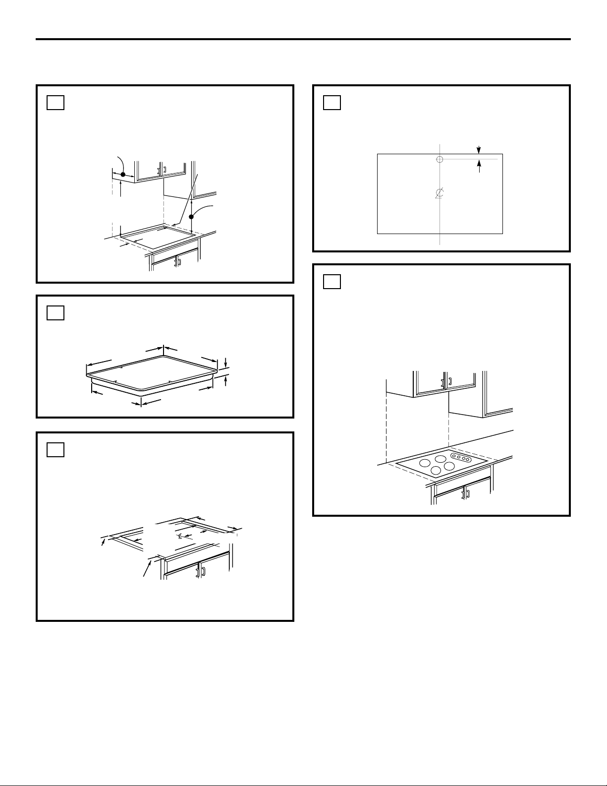
PREPARING THE OPENING
MAINTAIN THE FOLLOWING
MINIMUM CLEARANCE
DIMENSIONS
1
OVERALL COOKTOP
DIMENSIONS
2
CUTOUT DIMENSIONS OF
COUNTERTOP
To ensure accuracy, it is best to make
a template when cutting the opening
in the counter.
3
RECOMMENDED GAS SUPPLY
LOCATION FROM BACKWALL
4
MAKE SURE WALL
COVERINGS, COUNTERTOP
AND CABINETS AROUND
COOKTOP CAN WITHSTAND
HEAT (UP TO 200°F)
GENERATED BY COOKTOP
5
13″ MAX. Depth of unprotected
overhead cabinets
6″ MIN. clearance from
cutout to side wall on
the right of the unit
18″ MIN. height
from countertop
to nearest cabinet
on either side of
unit
3-3/4″ MIN. clearance
from cutout to side wall
on the left of the unit
Cooktop
19-1/8” width cut
16-15/16″
33-7/8”
length
of cut
2-1/4” Min. Between
cutout and the wall
behind the cooktop
33-11/16″
36″
21″
3″
18-7/8″
30″ MIN. clearance from
countertop to unprotected
overhead surface
2-1/2” Min. from
front edge of
cutout and front
edge of countertop
1” Min. From Backwall
From Cutout
Center Line
Recommended
gas supply
location
Wall covering,
cabinets and
countertop
must withstand
heat up to
200°F
3 3/4 MIN.
Page 5
5
Installation Instructions
INSTALLING THE COOKTOP UNIT
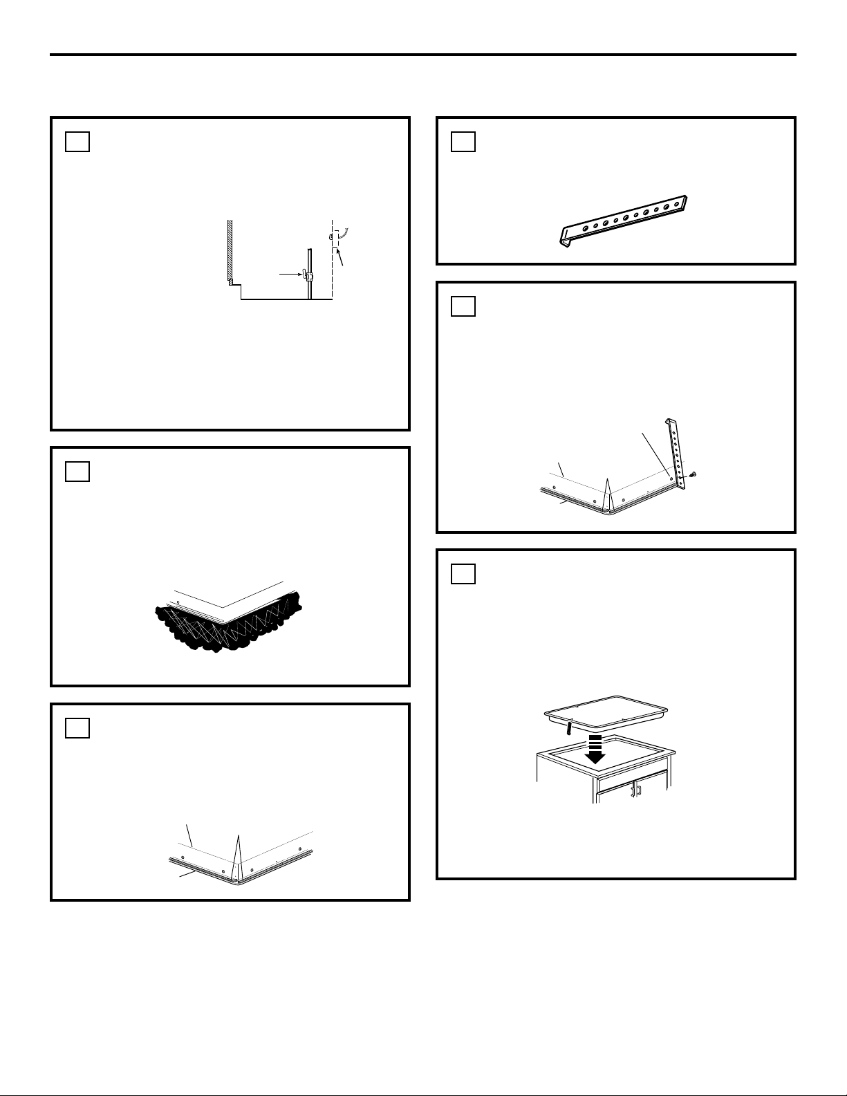
LOCATE ELECTRICAL OUTLET
AND GAS SHUT-OFF VALVE
BENEATH CABINET
Install a manual shut-off valve in the gas line
in an easily accessible location outside the
cooktop. Be sure you know how and where to
shut off the gas supply to the cooktop. Install
the electrical outlet 12″ below the countertop.
1
NEVER REUSE
OLD CONNECTORS
WHEN INSTALLING
THIS UNIT.
PROTECT SURFACE OF
COOKTOP
Place a towel or tablecloth onto the
countertop. Lay the cooktop upside down
onto the protected surface.
2
ATTACH FOAM TAPE
(glass maintop models only)
Apply the foam tape around the outer edge
of the glass. Do not overlap the foam tapes.
3
LOCATE MOUNTING PARTS
Remove the hold down brackets from the
literature package.
4
ATTACH BRACKETS TO
COOKTOP
Remove the screw from the bottom of the
cooktop and screw the hold-down bracket
to the side of the cooktop unit. Repeat for
opposite side of cooktop.
5
INSERT COOKTOP INTO
CUTOUT
Insert the cooktop centered into the cutout
opening. Make sure the front edge of the
countertop is parallel to the cooktop. Make
final check that all required clearances are met.
Once the unit is in place, screw the holddown bracket into the cabinet sides to secure
the unit into place.
6
Shut-Off
Valve
Electrical
Outlet 12″
Below
Countertop
Bottom of cooktop
Cloth under Cooktop
Cooktop
Pre-drilled
hole
Foam Tapes
Bottom of
Cooktop
Cooktop
Glass
Foam Tapes
Bottom of Cooktop
Cooktop Glass
Page 6
6
Installation Instructions
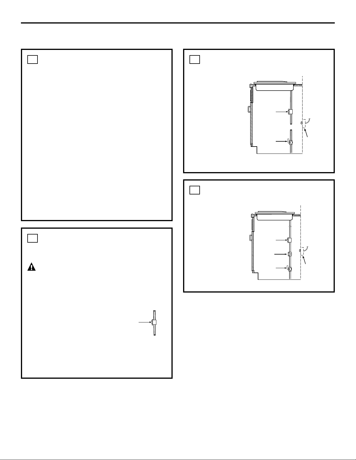
INSTALLING THE COOKTOP
PROVIDE ADEQUATE
GAS SUPPLY
This cooktop is designed to operate on
natural gas at 4″ of water column pressure.
It is shipped from the factory set for natural
gas. The convertible pressure regulator
supplied with the unit must be connected in
series with the manifold of the cooktop and
must remain in series with the supply line
regardless of whether natural or L.P. gas is
being used. FOR PROPER OPERATION,
THE MAXIMUM INLET PRESSURE TO THE
REGULATOR MUST BE NO MORE THAN
14″ OF WATER COLUMN PRESSURE. For
checking the regulator, the inlet pressure
must be at least 1″ (or 3.4 KPA) greater than
the regulator output setting. If the regulator is
set for 4″ of water column pressure, the inlet
pressure must be at least 5″. If the regulator
is set for 10″, the inlet pressure must be at
least 11″. The gas supply line to the cooktop
should be 1/2″ or 3/4″ pipe.
1
INSTALL REGULATOR
NEVER REUSE OLD CONNECTORS WHEN
INSTALLING THIS COOKTOP.
WARNING: Never reuse old
flexible connectors. The use of old flexible
connectors can cause gas leaks and personal
injury. Always use new flexible connectors
when installing a gas appliance.
To reduce the likelihood of gas leaks, apply
teflon tape or a thread compound approved
for use with LP or Natural gases to all
threaded connections.
2
Screw a section of pipe
onto each end of the
pressure regulator.
INSTALL REGULATOR ONTO
BURNER BOX BOTTOM
Screw the
regulator and
pipe connection
into the burner
box bottom.
Make sure the
top of the
regulator is
facing towards
the cabinet front,
easily accessible
through the
cabinet doors.
3
COMPLETE CONNECTION
WITH A COUPLING
Install a coupling
between the
regulator and
the shu-off valve
to complete the
connection.
4
Pressure
Regulator
Pressure
Regulator
Shut-Off
Valve
Electrical
Outlet 12″
Below
Countertop
Pressure
Regulator
Shut-Off
Valve
Coupling
Electrical
Outlet 12″
Below
Countertop
Page 7
7
Installation Instructions
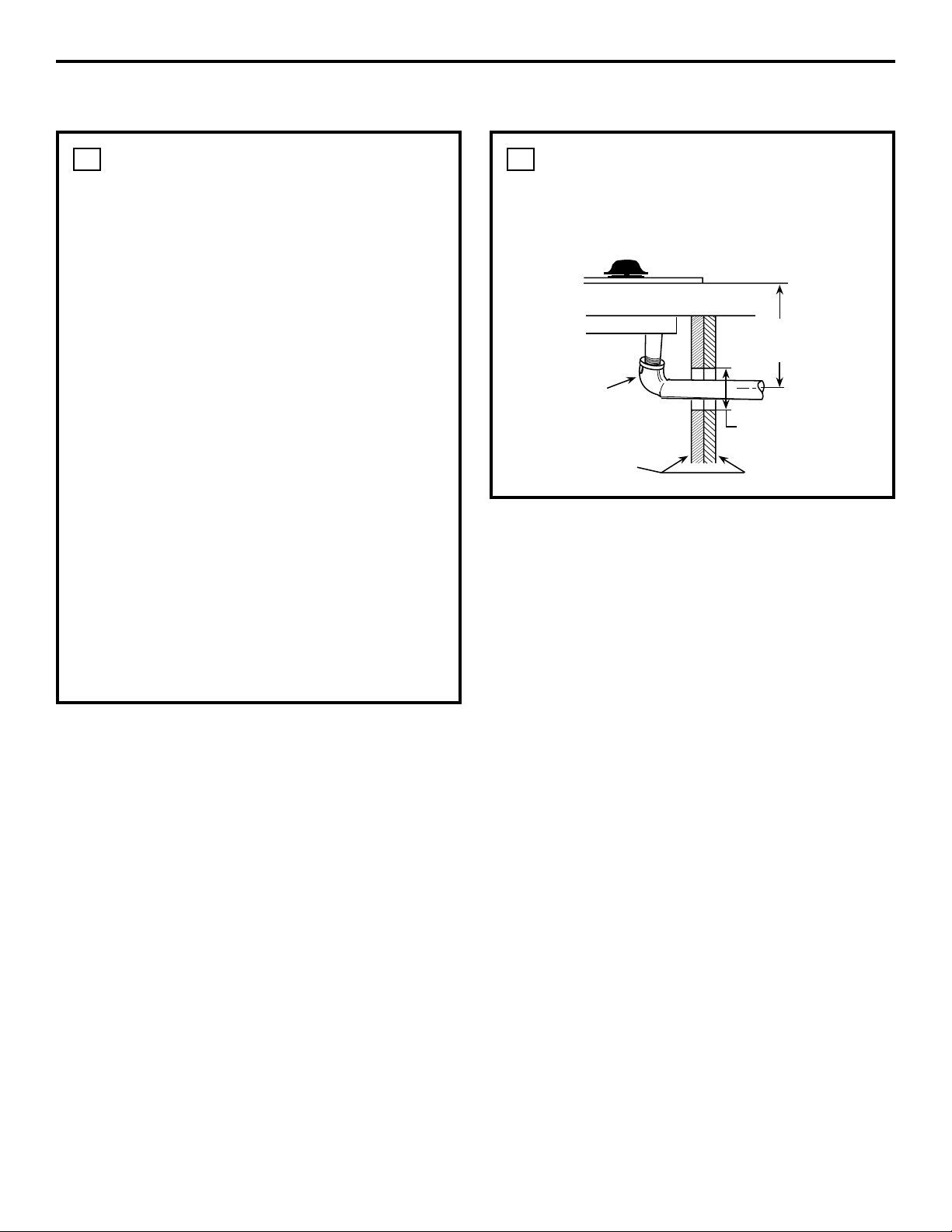
INSTALLATION OVER
BUILT-IN OVEN
See built-in oven installation for complete
installation instructions.
6
CHECK FOR LEAKS
After connecting the cooktop to gas, check
system for leaks with a manometer. If a
manometer is not available, turn the gas
supply on to the cooktop and use a liquid
leak detector at all joints and connections
to check for leaks. Tighten all connections
if necessary to prevent gas leakage in the
cooktop or supply line. Check alignment of
valves after connecting the cooktop to the
gas supply to be sure the manifold pipe has
not been moved. A misalignment could cause
the valve knob stem to rub on the control
panel, resulting in a gas leak at the valve.
DO NOT USE OPEN FLAME TO CHECK
FOR LEAKS!
Disconnect this cooktop and its individual
shutoff valve from the gas supply piping
system during any pressure testing of
that system at test pressures greater than
1/2″ psig.
Isolate the cooktop from the gas supply
piping system by closing its individual shutoff
valve during any pressure testing of the gas
supply system at test pressures equal to or
less than 1/2″ psig.
5
5″ To Center of
2″ Dia. Hole From
Countertop
2″ Dia. Hole
(20 7/8″ from front
of Countertop to
Hole Center)
Cabinet Sides
90° Street El
Page 8
8
Installation InstructionsInstallation Instructions
INSTALLATION—ELECTRICAL CONNECTIONS
EXTENSION CORDS
Because of potential safety hazards under
certain conditions, we strongly recommend
against the use of an extension cord.
However, if you still elect to use an extension
cord, it is absolutely necessary that it be a
UL listed 3-wire grounding type appliance
extension cord and that the current carrying
rating of the cord in amperes be equivalent
to or greater than the branch circuit rating.
Such extension cords are obtainable through
your local appliance dealer.
IMPORTANT: (Please read carefully)
FOR PERSONAL SAFETY, THIS APPLIANCE
MUST BE PROPERLY GROUNDED.
1
ELECTRICAL SUPPLY AND
OUTLET
An adequate electrical supply and outlet must
be used to operate the electrical parts of your
cooktop.
The power cord of this appliance is
equipped with a 3-prong (grounding)
plug which must be used with a properly
grounded 3-hole outlet with a standard
120 Volt, 60 cycle AC household current.
If you do not have a 3-hole grounded
outlet, have a qualified electrician
change your old one.
A grounding adaptor will be needed
to convert the old one until the outlet
can be replaced. This method is only
temporary, and a qualified electrician
should test it to be sure it meets
requirements.
C
B
A
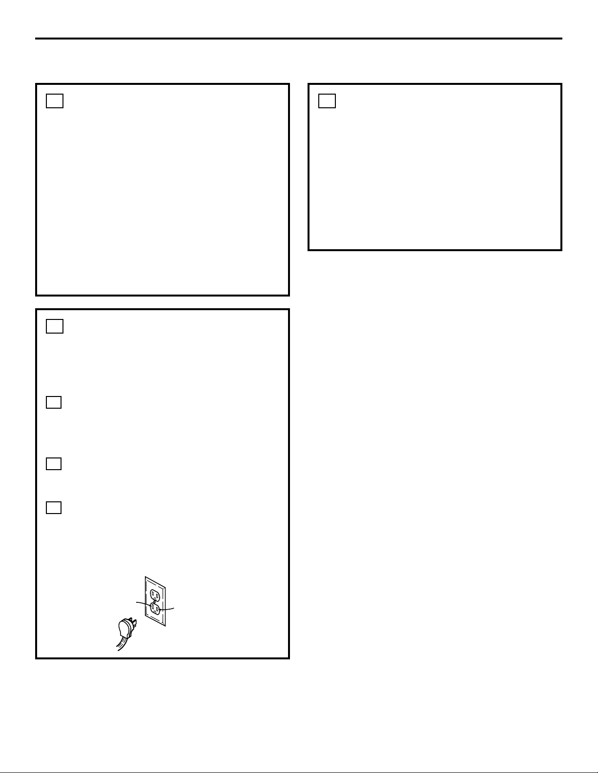
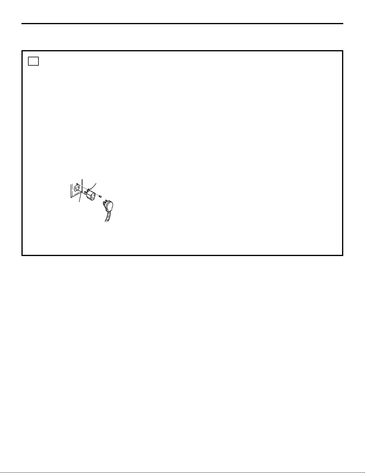
2
TWO-PRONG WALL
RECEPTACLE
Where a standard 2-prong wall receptacle is
encountered, it is the personal responsibility
and obligation of the customer to have it
replaced with a properly grounded 3-prong
wall receptacle.
Do not under any circumstances cut or
remove grounding prong from the cooktop
cord. Failure to provide proper polarization
may create a hazardous condition.
3
N
L
Ensure proper
ground and
firm connection
before use
Page 9
9
Installation Instructions
USAGE SITUATIONS WHERE
APPLIANCE POWER CORD
WILL BE DISCONNECTED
INFREQUENTLY
For 15 amp circuit only. Do not use an adaptor
on a 20 amp circuit. Where local codes permit,
a TEMPORARY CONNECTION may be made to
a properly grounded two-prong wall receptacle
by the use of a UL-listed adaptor available at
most hardware stores. The larger slot in the
adaptor must be aligned with the large slot in
the wall receptacle to provide proper polarity
in the connection of the power cord.
CAUTION:
Attaching the adaptor ground
terminal to the wall receptacle cover screw
does not ground the appliance unless the
screw is metal, and not insulated, and the wall
receptacle is grounded through the house
wiring. The customer should have the circuit
checked by a qualified electrician to make sure
the receptacle is properly grounded.
When disconnecting the power cord from the
adaptor, always hold the adaptor with one
hand. If this is not done, the adaptor ground
terminal is very likely to break with repeated
use. Should this happen, DO NOT USE the
appliance until a proper ground has again
been established.
Usage situation where appliance power cord
will be disconnected frequently.
Do not use an adaptor plug in these situations
because disconnection of the power cord
places undue strain on the adaptor and leads to
eventual failure of the adaptor ground terminal.
The customer should have the 2-prong
receptacle replaced with a 3-prong (grounding)
receptacle by a qualified electrician before
using the appliance.
4
Ensure proper ground and
firm connection before use
Align large
prongs/slots
Temporary Method
(Adaptor plugs not permitted in Canada)
Page 10
10
Installation Instructions
ASSEMBLING THE COOKTOP
BURNERS
The electrode of the spark igniter is exposed.
Be careful not to push any cooktop controls
while the top of the burner is removed.
Do not remove the top or touch the electrode
of any burner while another burner is turned
on. Electrical shock might result.
FOR PORCELAIN COOKTOPS
Place the burner head on the burner
base so that the pins match up with the
slots on the base.
Position the burner cap on the burner
head.
Place the burner grate over the burner
assembly on the porcelain units. The
bottoms of the burner grates have feet
that fit into corresponding indentations
in the cooktop.
C
B
A
1
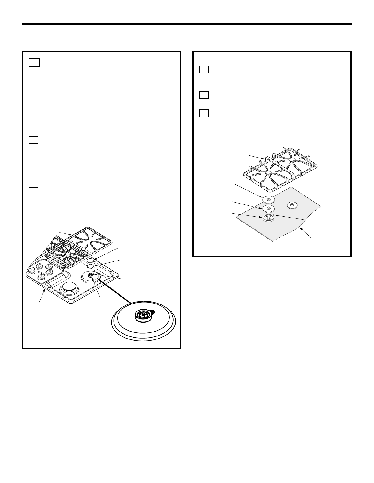
COOKTOP BURNERS
FOR GLASS CERAMIC COOKTOPS
Place the burner head on the burner
base, so that the pins match up with the
slots on the base.
Position the burner cap on the burner
head.
Place the burner grate over the burner
assembly on the ceramic units. The grate
fits over the raised area on the burner
head.
C
B
A
Burner Cap
Burner Head
Spark Igniter
Burner Box
Bottom
Burner Base
Burner Grate
Burner Cap
Burner
Head
Spark Igniter
Glass
Maintop
Burner Base
Burner Grate
Page 11

11
Installation Instructions
CHECK IGNITERS
Operation of the electric igniters should be
checked after the cooktop and supply line
have been carefully checked for leaks and the
cooktop has been connected to the electrical
power.
Push and turn a burner valve to the LITE
position.
• The burner valve should light when gas
is available to the burner.
• Once the burner lights, it should be
turned out of the LITE position.
Try each valve separately until all
burners have been checked.
B
A
2
BURNER IGNITION
Cooktop Spark Ignition—When you turn
the cooktop knob to LITE, the spark igniter
makes a series of electric sparks (ticking
sounds) which light the burner. During a
power failure, the burners will not light
automatically. In an emergency, a cooktop
burner may be lit with a match by following
the steps below.
WARNING: Lighting gas burners
with a match is dangerous. You should
match light the cooktop burners only in
an emergency.
Light a match and hold the flame near
the burner you want to light. Wooden
matches work best.
Push in and turn the control knob slowly.
Be sure you are turning the correct knob
for the burner you are lighting.
NOTE: If the burner does not light within five
seconds, turn the knob off and wait one minute
before trying again.
B
A
3
THE BURNER FLAMES
Turn each burner on. Flames should be blue
in color with no trace of yellow. The burner
flames should not flutter or blow away from
the burner. The inner cone of the flame
should be between 1/2″ and 3/4″ long.
WARNING:
If you attempt to
measure the inner cone of the flame, please
use caution. Burns could result.
4
Burners should be checked frequently
Cooktop Burner
1/2″
to
3/4″
Page 12

12
Installation Instructions
OPERATION CHECKLIST
Double check to make sure everything in
this guide has been completed. Rechecking
steps will ensure safe use of the cooktop.
Make sure all controls are left in the OFF
position.
Make sure the flow of combustion
and ventilation air to the cooktop is
unobstructed.
The serial plate for your cooktop is
located on the bottom of the burner box.
In addition to the model and serial
numbers, it tells you the ratings of the
burners and the type of fuel and pressure
the cooktop was adjusted for when it
left the factory.
When ordering parts, always include the
serial number, model number and a code
letter to ensure proper replacement parts.
Recheck Steps:
Double check to make sure everything
in this guide has been completed.
Rechecking steps will ensure safe
use of the cooktop.
F
E
D
C
B
A
Page 13

13
Installation Instructions
MAKING THE LP CONVERSION
SAFETY INFORMATION YOU
SHOULD KNOW
The pressure regulator and burner orifices
are set for natural gas. To use Propane Gas,
the regulator and burner orifices must be
converted. The LP orifice spuds for the
cooktop burners can be located in the
literature package.
CAUTION: The cooktop, as shipped
from the factory, is set for use with natural
gas. If you wish to use your cooktop with
Liquefied Petroleum (Propane) gas, you must
first replace the orifices and convert the
pressure regulator.
WARNING:
This conversion must
be performed by a qualified installer or gas
supplier in accordance with the manufacturer’s
instructions and all codes and requirements
of the authority having jurisdiction. Failure
to follow instructions could result in serious
injury or property damage. The qualified
agency performing this work assumes
responsibility for the conversion.
CAUTION:
The following adjustments
must be made before turning on the burner.
Failure to do so could result in serious injury.
Be sure pressure regulator has been
converted as described in Step 2.
1
ADJUST YOUR COOKTOP FOR
USE WITH LP GAS
Disconnect all electrical power, at the
main circuit breaker or fuse box.
Shut off the gas supply to the cooktop
by closing the manual shut-off valve.
Adjust the pressure regulator, by the
following instructions:
• Unscrew the cap.
• Place your thumb against the flat side
of the spring retainer and press down
to remove the retainer.
• Carefully look at the spring retainer to
locate the NAT or LP position.
• Turn the spring retainer over so that
LP is showing on the bottom.
• Snap the retainer back into position.
C
B
A
2
Gasket
Cap
Spring
Retainer
L.P./Propane
Position
NAT.
Position
Pressure Regulator
LP
NAT
LP
NAT
NAT
LP
NAT
LP
FOR OFF
DOWN
Page 14

14
Installation Instructions
MAKING THE LP CONVERSION (CONT.)
CHANGE COOKTOP BURNER
ORIFICES
Remove the top grates, burner caps,
burner heads and burner bases.
Remove the
electrodes from the
burner base. Using
a No. 15 “Torx” head
driver bit, remove
the screws holding
the burner base in
position.
Using a 7mm or
9/32″ nut driver,
remove the top
burner orifices.
These may be
accessed through the
hole in the cooktop.
NOTE: The orifices have
a spring-loaded retaining
ring around the hex head
to hold the orifice in the
nut driver during
installation and removal.
A slight amount of force is required to push
the nut driver down over the ring.
Locate the LP/Propane orifices shipped
inside the literature package. They
will have a digit number and the letter
“L” on the side. (Important: Save the
orifices removed from the appliance
for future use.)
Each orifice will show a series of
engraved marks, (I, II, III or X),
located on the top.
These marks denote the precise location of
each orifice to the cooktop burner.
D
C
B
A
3
Units with 4 burners
Units with 5 burners
Install the LP/Propane orifices in
their precise locations as noted in the
illustrations above.
Replace the burner bases, heads, caps
and top grates. (NOTE: When re-attaching
the burner bases to glass top units,
tighten screws to a maximum of
10 in.-lbs torque.)
Save the orifices removed from the
appliance for future use.
G
F
E
Remove
This
Assembly
Orifice Spud Located
Through This Opening
Retainer
Ring
X
I II III X
Page 15

15
Installation Instructions
ADJUST BURNER FLAMES
Turn all burners full on and check the
flames. They should be blue in color with
no trace of yellow. Foreign particles in
the gas line may cause an orange flame
at first, but this will soon disappear.
Turn the control valve to low position
while observing the flame.
To make adjustment, remove the control
knobs. Insert a screwdriver through
access hole in valve switch. Engage
adjustment screw in valve.
• If the flames were too small or
fluttered, open the valve more than
the original setting.
• If the flames blew away from the
burner, close the valve more than
the original setting.
Make the adjustment by slowly turning
the screw until flame appearance is
correct.
D
C
B
A
4
Adjust the low flame setting using the valve
bypass screw as follows:
Low-setting adjustments must be made
with two other burners in operation on
a medium setting. This prevents the low
flame from being set too low, resulting in
the flame being extinguished when other
burners are turned on.
Testing Flame Stability:
Test 1 – Turn the knob from “HI” to
“LOW” quickly. If the “LOW”
flame goes out, increase the
flame size and test again.
Test 2 – With the burner on the “LOW”
setting, open and close the
cabinet door under the cooktop.
If the flame is extinguished by
the air currents created by the
door movement, increase the
flame height and test again.
Flame Recheck:
After the adjustment is made, turn all burners
off. Ignite each burner individually. Observe
the flame at the “HI” position. Rotate the
valve to the “LO” position and be sure that
the flame size decreases as the valve is
rotated counterclockwise.
TO CONVERT THE COOKTOP BACK TO
NATURAL GAS, REVERSE THE STEPS
UNDER MAKING THE LP CONVERSION.
Once the conversion is complete and
checked ok, fill out the LP sticker and
include your name, organization and date
conversion was made. Apply the sticker
near the cooktop gas inlet opening to alert
others in the future that this appliance has
been converted to LP gas. If converting back
to natural gas from LP, please remove the
sticker so others know the appliance is set
to use natural gas.
F
E
Page 16

16
Notes
Printed in the United States
Page 17

1
OUTILS DONT VOUS AUREZ BESOINS
MATÉRIAUX DONT VOUS POUVEZ AVOIR BESOIN
229C4053P522-2
31-10539-2 05-03 JR
Questions? Appelez le Centre de réponse 1.800.361.3400 ou visitez notre site
Web à l’adresse : www.electromenagersge.ca
Instructions
Table de cuisson scellée
d’installation
au gaz de 91 cm (36″)
JGP628, JGP962, JGP963, ZGU36
AVANT DE COMMENCER
Avant de commencer, lisez attentivement la
totalité de ces instructions.
•
IMPORTANT — Conservez ces
instructions pour votre inspecteur local.
•
IMPORTANT — Respectez toutes
les ordonnances et les codes locaux.
• Note à l’installateur – Assurez-vous de
laissez ces instructions au consommateur.
• Note au consommateur – Conservez ces
instructions pour référence future.
• La garantie ne couvre aucune panne due à
une mauvaise installation.
AVERTISSEMENT — Cet
appareil coit être bien mis à la terre.
•
IMPORTANT — Vous devez
vérifier que cet appareil n’a pas de fuite
conformément aux instructions du
fabricant.
• L’installateur est responsable d’une bonne
installation et la garantie ne couvre aucune
panne due à une mauvaise installation.
PIÈCES COMPRISES
2 Supports de
fixation
Robinet
d’alimentation de gaz
Raccords de tuyaux
Raccord flexible de gaz approuvé par l’ACNOR
DI min 3/8’’, Jonction NPT 1/2
Agent de scellement
de tuyau
Scie sauteuse
Crayon
Lunettes de sécurité
Perceuse à main ou
électrique et foret de 1/8″
Règle ordinaire ou de
vérification
Bandes de mousse
(Pour les modèles à
surface en verre
seulement)
2 vis
Tournevis Phillips
Clé à tuyau
Page 18

2
Instructions d’Installation
POUR VOTRE SÉCURITÉ
AVERTISSEMENT —
Si vous ne suivez pas exactement les
instructions de ce manuel, vous risquez
d’occasionner un incendie, une explosion
ou une fuite de gaz, qui peuvent provoquer
des dommages matériels, des blessures
corporelles ou la mort.
Ne conservez pas ou n’utilisez jamais
d’essence ou d’autres liquides ou vapeurs
inflammables à proximité de cet appareil ou
de tout autre appareil ménager!
CI QUE VOUS DEVEZ
FAIRE SI VOUS SENTEZ
LE GAZ:
• N’essayez jamais d’allumer un appareil
électroménager. Ne touchez à aucun
commutateur d’électricité, n’utilisez jamais
un téléphone dans votre bâtiment.
• Appelez immédiatement votre fournisseur
de gaz à l’aide du téléphone d’un voisin.
Suivez les instructions de votre fournisseur
de gaz.
• Si vous ne pouvez pas entrer en
communication avec votre fournisseur
de gaz, appelez les pompiers.
L’installation et service de votre table de
cuisson doivent être faites par un installateur
qualifié, un technicien de service ou votre
fournisseur de gaz.
INSTRUCTIONS IMPORTANTES DE SÉCURITÉ
La conception de votre table de cuisson a été
approuvé par l’ACNOR International. Vous
trouverez des précautions ô prendre en
matière de sécurité dans votre Guide
d’utilisation et de soins. Lisez-les
attentivement.
• L’installation de votre table de cuisson
doit se conformer aux codes locaux ou, en
l’absence de codes locaux, au National Fuel
Gas Code, ANSI Z223.1 Dernière édition.
• Assurez-vous que votre table de cuisson
soit bien installée par un installateur qualifié
ou un technicien de service.
• Pour éliminer tout mouvement corporel
au dessus des brûleurs de votre table de
cuisson, évitez de placer des armoires de
cuisine au dessus des brûleurs.
• N’installez jamais votre appareil près d’une
porte d’entrée ou à un emplacement où un
courant d’air peut gêner son usage.
Page 19

3
Instructions d’Installation
BESOINS D’ÉLECTRICITÉ
Cet appareil ménager doit être livré avec le
bon voltage et la bonne fréquence et branché
à son propre circuit de dérivation bien mis à
la terre, protégé par un disjoncteur ou un
fusible qui ont l’ampérage noté sur la plaque
de cotation
Nous vous recommandons de faire brancher
le câblage électrique et la fiche de votre
cuisinière par un électricien qualifié. Après
l’installation, demandez à l’électricien de vous
montrer l’emplacement de votre coupe-circuit
principal.
Demandez à votre entreprise de services
publics les codes électriques en vigueur
dans votre région. En ne câblant pas votre
cuisinière conformément aux codes en
vigueur, vous provoquez une situation
dangereuse. En l’absence de codes, vous
devez câbler et isoler votre cuisinière
conformément aux exigences du Canadian
Electrical Code.
Page 20

4
Instructions d’Installation
Pour préparer l’ouverture de la surface
de cuisson, vous devez vous assurer
que l’intérieur de l’armoire ne touche
pas la table de cuisson (consultez la
section sur la préparation de
l’ouverture).
Retirez les matériaux d’emballage et
la trousse de documentation de votre
table de cuisson avant de commencer
à l’installer.
B
A
LISTE DE VÉRIFICATION AVANT INSTALLATION
Enlevez les instructions d’installation
de la trousse de documentation et
lisez-les soigneusement avant de
commencer.
Assurez-vous de bien ranger toute la
documentation, l’utillisation et less
soins, les installation, etc. dans un
endroit sûr pour référence future.
Assurez-vous d’avoir tous les outils et
tous les matéraux nécessaires avant de
commencer à installer votre table de
cuisson.
Votre maison doit être alimentée en
courant électrique adéquat pour vous
permettre de bien utiliser en toute
sécuité votre table de cuisson.
(Consultez la section sur les besoins
d’électricité.)
Pour installer votre table de cuisson
dans votre maison, assurez-vous de
vous conformer scrupuleusement à
tous les codes et à toutes les
ordonnances locales.
Assurez-vous que les revêtements
de mur, le comptoir et les armoires
autour de la table de cuisson puissent
supporter la chaleur [pouvant atteindre
93°C (200°F)] produite par la table de
cuisson.
G
F
E
D
C
Trousse de
documentation
Emballage en
mousse de
polystyrène
Table de Cuisson
O
H
O
T
N
Page 21

5
Instructions d’Installation
PRÉPARATION DE L’OUVERTURE
VOUS DEVEZ RESPECTER LES
DÉGAGEMENTS MINIMAUX
SUIVANT
1
DIMENSIONS DU DÉCOUPAGE
DE LA TABLE DE CUISSON
2
DIMENSIONS TOTALES DE LA
TABLE DE CUISSON
Pour assurer la justesse du découpage,
il vaut mieux faire un gabarit pour
couper l’ouverture dans le comptoir.
3
EMPLACEMENT
RECOMMANDÉ DE
L’ALIMENTATION DE GAZ À
PARTIR DU MUR ARRIÈRE
4
ASSUREZ-VOUS QUE LES
REVÊTEMENTS MUR, LE
COMPTOIR ET LES ARMOIRES
AUTOUR DE LA TABLE DE
CUISSON PUISSENT
SUPPORTER LA CHALEUR
(POUVANT ATTEINDRE 93°C
[200°F])
5
Profondeur max de 33 cm (13″) des
armoires en surplomb non protégées
Dégagement min. de
15 cm (6″) découpage
au mur de côté à
droite de l’appareil
Hauteur min
de 45 cm (18″)
du comptoir à
l'armoire la
plus proche de
chaque côté
de l'appareil
Dégagement min
de 10 cm (3-3/4″) du
découpage au mur de
côté droite de l’appareil
Table de cuisson
Largeur du découpage
48,5 cm (19-1/8″)
43 cm
(16-15/16″)
86 cm (33-7/8 po)
longueur du découpage
Distance min de 5,7 cm
(2-1/4″) de découpage
au mur derrière la table
de cuisson
86 cm (33-11/16″)
91 cm (36″)
53 cm (21″)
8 cm (3″)
48 cm (18-7/8″)
Dégagement min. de 76 cm (30″)
du comptoir à la surface en non
surplomb non protégées
6,4 cm (2-1/2″) Distance min.
de l'arête avant du
découpage de l'arrête avant
de la table de cuisson
2,5 cm (1″) min. du mur arrière
Emplacement
recommandé de
l'alimentation
de gaz
Du
découpage
á la ligne
du centre
Les revêtements de
mur, les armoires et
le comptoir doivent
pouvoir supporter
une chaleru pouvant
atteindre 93°C (200°F)
3 3/4 MIN.
Page 22

6
Instructions d’Installation
INSTALLATION DE LA TABLE DE CUISSON
PLACEZ LA PRISE
D’ALIMENTATION
ÉLECTRIQUE ET LE ROBINET
D’ALIMENTATION DE GAZ
AU-DESSOUS DE L’ARMOIRE
Montez le robinet d’alimentation manuel sur
le tuyau de gaz à un emplacement facile à
atteindre en dehors de la table de cuisson.
Assurez-vous de savoir où et comment
couper l’alimentation de gaz à la table de
cuisson. Montez la prise électrique 30 cm
(12″) au-dessous du comptoir.
1
N’UTILISEZ JAMAIS
DES RACCORDS
USAGÉS POUR
INSTALLER CET
APPAREIL.
PROTÉGEZ LA SURFACE DE
LA TABLE DE CUISSON
Placez une serviette ou un torchon sur le
comptoir. Posez la table de cuisson à l’envers
sur la surface protégée.
2
TROUVEZ LES PIÈCES DE
MONTAGE
Retirez les supports de fixation de la trousse
de documentation.
4
FIXEZ LES SUPPORTS DE
FIXATION À LA TABLE DE
CUISSON
Enlevez la vis d’un côté de la table de
cuisson, vissez un support de fixation à un
côté de la table de cuisson. Répétez la même
opération de l’autre côté de la table de
cuisson.
5
INSÉREZ LA TABLE
DE CUISSON DANS
L’OUVERTURE DÉCOUPÉE
Insérez la table de cuisson centrée dans
l’ouverture découpée. Assurez-vous que
l’arrête de devant du comptoir soit bien
parallèle à l’extrémité de la surface de
cuisson. Faites une vérification finale pour
vous assurer de bien respecter tous les
dégagements.
Une fois la table de cuisson en place,
vissez les supports de fixation aux côtés de
l’armoire pour tenir la table de cuisson bien
en place.
6
Rodinet d’arrêt
d’alimentation
Prise électrique
30 cm (12″)
sous le
comptoir
Envers de la table de cuisson
Linge sous la table de cuisson
Table de cuisson
Support
de fixation
Bandes de
mousse
Bas de la table
de cuisson
Verre de la table
de cussion
ATTACHEZ LA BANDE DE MOUSSE
(modèles de la table de verre seulement)
Appliquez la bande de mousse autour du
bord extérieur du verre. Ne superposez pas
les bandes de mousse.
3
Bandes de
mousse
Bas de la table
de cuisson
Verre de la table
de cuisson
Page 23

7
Instructions d’Installation
INSTALLATION DE LA TABLE DE CUISSON
PRÉVOYEZ UNE
ALIMENTATION EN GAZ
ADÉQUATE
Cette table de cuisson est concue pour
fonctionner au gaz naturel à une pression de
4″ de colonne d’eau. Elle est expédiée de la
fabrique réglée pour le gaz natural. Le
régulateur de pression convertible fourni
avec l’appareil doit être raccordé en série
au collecteur de la table de cuisson et doit
continuer le tuyau d’alimentation que l’on
utilise du gaz naturel ou du gaz propane.
POUR UNE BONNE UTILISATION, LA
PRESSION D’ENTRÉE MAXIMUM AU
RÉGULATEUR NE DOIT PAS ÊTRE
SUPÉRIEURE À 14″ DE COLONNE D’EAU.
Pour correspondre au régulateur, la pression
d’alimentation doit être au noins 1″, ou
3,4KPA supérieure au réglage de sortie du
régulateur. Si le régulateur est réglé une
pression de 4″ de colonne d’eau, la pression
d’alimentation doit être au moins égale à 5″.
Si le régulateur est réglé pour 10″, la pression
d’alimentation doit être au moins égale à 11″.
Le tuyau d’alimentation de gaz à la table de
cuisson doit être un tuyau de 1 cm (1/2″) ou
de 2 cm (3/4″).
1
INSTALLATION DU
RÉGULATEUR
N’UTILISEZ JAMAIS DE RACCORDS
USAGÉS POUR INSTALLER CETTE TABLE
DE CUISSON.
AVERTISSEMENT : N’utilisez
jamais de raccord souple usagé. L’utilisation
de raccords souples usagé peut occasionner
des fuites de gaz et des blessures
corporelles. Utilisez toujours les raccords
souple neuf pour installer un appareil à gaz.
Pour réduire la probabilité de fuite de gaz,
posez sur tous les raccords filetés du ruban
d’étanchéité pour joint ou de la pâte
lubrifiante approuvée pour le gaz naturel
ou le gaz propane.
2
Vissez une section
du tuyau dans chaque
extrémité du régulateur
de pression.
INSTALLEZ LE RÉGULATEUR
EN BAS DE LA BOÎTE DU
BRÛLEUR
Vissez le
régulateur et
le raccord de
tuyau en bas de la
boîte du brûleur.
Assurez-vous
que le haut du
régulateur face
à l’avant de
l’armoire et
soit facilement
accessible par
les portes de
l’armoire.
3
TERMINEZ LE RACCORDEMENT
PAR UN JOINT
Montez un joint
entre le régulateur
et le robinet d’arrêt
d’alimentation
pour terminer le
raccordement.
4
Régulateur
de
Pression
Régulateur
de
pression
Rodinet d’arrêt
d’alimentation
Prise
électrique
30 cm (12″)
sous le
comptoir
Joint
Régulateur
de
pression
Rodinet d’arrêt
d’alimentation
Prise
électrique
30 cm (12″)
sous le
comptoir
Page 24

8
Instructions d’Installation
INSTALLATION SUR UNE
CUISINIÈRE ENCASTRÉE
Consultez l’installation de la cuisinière
encastrée pour les instructions complètes
d’installation.
6
INSTALLATION DE LA TABLE DE CUISSON
(SUITE)
VÉRIFIEZ QU’IL N’Y AIT PAS
DE FUITE
Vérifiez qu’il n’y ait pas de fuite. Après avoir
raccordé la table de cuisson au gaz, vérifiez
le système avec un manomètre pour vous
assurer qu’il n’y ait pas de fuite. Si vous
n’avez pas de manomètre, branchez
l’alimentation de gaz à chaque raccord et
à chaque joint pour vérifier qu’il n’y ait
pas de fuite. Resserrez tous les raccords
si nécessaire pour empêcher toute fuite
de gaz de la table de cuisson ou du tuyau
d’alimentation. Vérifiez l’alignement des
robinets après avoir raccordé la table de
cuisson à l’alimentation de gaz pour vous
assurer que le collecteur n’ait pas bougé.
Un mauvais alignement peut occasionner
un frottement du corps du robinet contre
le panneau de réglage, ce qui provoquerait
une fuite de gaz au niveau du robinet.
N’UTILISEZ JAMAIS UNE FLAMME VIVE
POUR VÉRIFIER S’IL Y A UNE FUITE!
Débranchez cette table de cuisson et son
robinet d’arrêt d’alimentation du système
de tuyauterie d’alimentation de gaz pour
entreprendre tout test de pression du
système à une pression plus équale
ou moins de 1/2″ psig.
Isolez la table de cuisson du système de
tuyauterie d’alimentation de gaz en fermant
son robinet d’arrêt d’alimentation pour
entreprendre tout test de pression du
système à une pression équale ou
moins de 1/2″ psig.
5
12,7 cm (5″) du
comptoir au centre
du trou de 5 cm (2″)
de diamètre
Trou de 5 cm (2″) de
diamètre [53 cm (20
7/8″) du centre du trou
à l’avante du comptoir]
Côtés de l’armoire
Élev. de 90°
Page 25

9
Instructions d’Installation
INSTALLATION—RACCORDS ÉLECTRIQUES
RALLONGES
À cause du danger qu’elles font courir
dans certaines conditions, nous vous
recommandons instamment de nes pas
utiliser de rallonge. Cependant, si vous
devez utiliser une rallonge, il faut absolument
qu’elle soit homologuée UL, triphasée à
trois fils pour appareil électroménager et
que sa capacité électrique en ampères soit
équivalente ou supérieure à celle du circuit
électrique. Vous pourrez trouver une telle
rallonge chez votre revendeur d’appareils
électroménagers.
IMPORTANT :
(Veuillez lire avec soin)
POUR VOTRE SÉCURITÉ, PERSONNELLE,
VOUS DEVEZ BIEN MATTE À LA TERRE CET
APPAREIL.
1
ALIMENTATION ÉLECTRIQUE
ET PRISE
Vous devez utiliser une bonne alimentation
électrique et une bonne prise pour faire
fonctionner les éléments électriques de
votre table de cuisson.
Le cordon d’alimentation de votre
appareil est muni d’une fiche à trois
broches (avec mise à la terre) qui doit
être utilisée dans une prise électrique
bien mise à la terre, qui alimente
en courant ménager CA normal de
120 volts, 60 cycles.
Si vous n’avez pas de prise triphasée,
demandez à un électricien qualifié de
changer votre ancienne prise.
Vous aurez besoin d’une fiche
d’adaptation de mise à la terre pour
convertir votre ancienne prise jusqu’à
son remplacement. Cette méthode est
temporaire et un électricien qualifié doit
tester votre installation pour s’assurer
qu’elle se conforme aux exigences.
C
B
A
2
BIPHASÉE
Si vous avez une prise normale biphasée,
c’est la responsabilité et l’obligation
personnelle du client de la faire remplacer
par une prise murale triphasée bien mise
à la terre.
Ne coupez ou ne retirez jamais, en aucun
cas, la broche de mise à la terre du cordon
d’alimentation de la table de cuisson. Si vous
ne mettez pas bien votre appareil à la terre,
vous pouvez créer une situation dangereuse.
3
N
L
Assurez une
bonne mise à la
terre et un bon
contact avant
l'usage
Page 26

10
Instructions d’Installation
SITUATION D’UTILISATION OÙ LE
CORDON D’ALIMENTATION D’UN
APPAREIL ÉLECTROMÉNAGER
EST INFRÉQUEMMENT
DÉBRANCHÉ
Pour un circuit électrique de 15 ampéres
uniquement. N’utilisez jamais de fiche
d’adaptation sur un circuit de 20 ampéres.
Quand les codes locaux le permettent, vous
pouvez établir UN CONTACT TEMPORAIRE
avec une prise murale biphasée bien mise
à la terre en utilisant une fiche d’adaptation
homologuée UL en vente dans la plupart des
quincailleries. La fente la plus grande de
l’adaptateur doit être alignée à la plus grande
fente de la prise murale pour obtenir une
bonne polarité avec le cordon d’alimentation.
MISE EN GARDE :
Si vous fixez
la broche de mise à la terre de l’adaptateur
à une vis du couvercle de la prise murale,
cela ne met pas à la terre l’appareil, à la moins
que la vis soit en métal et ne soit pas isolée
et que la prise murale soit mise à la terre par
l’intermédiaire du câblage de la maison. Vous
devez faire vérifier le circuit par un électricien
qualifié pour vous assurer que la prise est bien
mise à la terre.
Quand vous débranchez le cordon
d’alimentation de d’adaptateur, tenez toujours
l’adapateur à la main. Si vous ne le faites pas,
vous casserez probablement la broche de mise
à la terre de l’adaptateur par un usage répété.
Si cela se produit, N’UTILISEZ JAMAIS
l’appareil avant de bien le remettre à la terre.
Situations d’utilisation où le cordon
d’alimentation d’un appareil électroménager
est fréquemment débranché.
N’utilisez jamais un adaptateur dans cette
situation, car en débranchant le cordon
d’alimentation, vous faites subir une tension
imprévue à l’adapateur et cela risque de
provoquer une panne de sa mise à la terre. Le
client doit faire remplacer sa prise biphasée par
une prise triphasée par un électricien qualifié
avant d’utiliser son appareil.
4
INSTALLATION—RACCORDS ÉLECTRIQUES
(SUITE)
Assurez une bonne
mise à la terre et un bon
contact avant l’usage
Alignez les grandes
broches aux
grandes fentes
Méthode temporaire
(les fiches d’adaptation ne sont
pas autorisée au Canada)
Page 27

11
Instructions d’Installation
MONTAGE DES BRÛLEURS DE
LA TABLE DE CUISSON
L’électrode de l’allume est exposée. Prenez
bien soin pousser de bouton de réglage de
la table de cuisson pendant que le haut du
brûleur est enlevé. N’enlevez jamais le haut
ou ne touchez jamais à l’électrode d’un
brûleur quand un autre brûleur fonctionne.
Cela peut provoquer des secousses
électriques.
POUR LES SURFACES DE CUISSON EN
PORCELAINE
Placez la tête de brûleur sur la base de
brûleur, de manière à ce que le taquet
corresponde à la fente de la base.
Mettez le capuchon de brûleur en place
sur la tête du brûleur.
Mettez la grille de brûleur sur l’ensemble
de brûleur ont des pieds qui vont dans
les indentations correspondantes de la
table de cuisson.
C
B
A
1
BRÛLEURS DE LA TABLE DE CUISSON
POUR LES SURFACES DE CUISSON
EN VITROCÉRAME
Placez la tête de brûleur sur la base de
brûleur, de manière à ce que le taquet
corresponde à la fente de la base.
Mettez le capuchon de brûleur en place
sur la tête du brûleur.
Mettez la grille de brûleur sur l’ensemble
de brûleur dans les appareils en
céramique. Les grilles vont sur les
surfaces en relief des têtes de brûleur.
C
B
A
Capuchon de brûleur
Tête de brûleur
Allumeur
Base de brûleur
Bas de la boîte
des brûleur
Grille de brûleur
Capuchon
de brûleur
Tête de
brûleur
Garniture avante
de la table
Allumeur
Base de
brûleur
Grille de brûleur
Page 28

12
Instructions d’Installation
BRÛLEURS DE LA TABLE DE CUISSON
(SUITE)
VÉRIFICATION DES
ALLUMEURS
Vous devez vérifier le fonctionnement
des allumeurs électriques après avoir
soigneusement vérifié qu’il n’y ait pas de
fuite au tuyau d’alimentation ou à la table
de cuisson et après avoir branché la table
de cuisson au courant électrique.
Poussez et tournez un robinet de brûleur
en position LITE (allumage).
• Le robinet du brûleur doit s’allumer
quand il y a du gaz dans le brûleur.
• Quand le brûleur allume, vos devez
l’enlever de sa la postiton LITE
(allumage).
Essayez chaque robinet séparément afin
de vérifier tous les brûleurs.
B
A
2
ALLUMAGE DES BRÛLEURS
Allume de la table de cuisson—Quand vous
tournez le bouton de la table de cuisson en
position LITE (allumage), l’allumeur fait une
série d’étincelles électriques (avec un
grésillement) qui allument le brûleur.
En cas de panne de courant, les brûleurs
ne s’allument pas automatiquement. En cas
d’urgence, vous pouvez allumer un brûleur
de table de cuisson au moyen avec une
allumette, en suivant les étapes suivantes:
AVERTISSEMENT : ll est
dangereux d’allumer un brûleur à gaz avec
une allumette. Vous ne devez allumer un
brûleur de table de cuisson avec une
allumette qu’en cas d’urgence.
Allumez une allumette et tenez la flamme
près du brûleur que vous voulez allumer.
Il vaut mieux utiliser une allumette
en bois.
Poussez et tournez lentement le bouton
de réglage. Assurez-vous de bien tourner
le bouton qui correspond au brûleur que
vous voulez allumer.
NOTE : Si le brûleur ne s’allume pas en
mois de cinq secondes, ramenez le bouton en
position d’arrêt et attendez une minute avant
d’essayer à nouveau.
B
A
3
LES FLAMMES DE BRÛLEURS
Allumez chaque brûleur. Les flammes doivent
être de couleur bleue, sans trace de jaune.
Les flammes de brûleur ne doivent ni
scintiller ni s’éloigner du brûleur. Le cône
intérieur de la flamme doit avoir de 1 cm
à 2 cm (1/2″ à 3/4″) de long.
AVERTISSEMENT :
Si vous
tentez de mesurer le cône intérieur de la
flamme, faites très attention. Vous pouvez
vous brûler.
4
Vous devez vérifier le bon fonctionnement de vos
brûleurs fréquemment
Brûleur de la Table
de Cuisson
1 cm à 2 cm
(1/2″ à 3/4″)
Page 29

13
Instructions d’Installation
LISTE DE VÉRIFICATION DE FONCTIONNEMENT
Vérifiez deux fois pour vous assurer
de vous être bien conformé à toutes les
instructions de ce guide. En vérificant
deuxième fois, vous vous assurez d’utiliser
la table de cuisson en toute sécurité.
Assurez-vous que tous les réglages soient
en position OFF (arrêt).
Assurez-vous qu’il n’y ait pas d’obstacle
à la circulation d’air de combustion et de
ventilation de la table de cuisson.
La plaque de série de votre table de
cuisson est située en bas de la boîte des
brûleurs. En plus du modèle et du numéro
de série, cette plaque vous indique la
notation des brûleurs, la catégorie de
carburant et la pression à laquelle la table
de cuisson a été réglée à sa sortie de la
fabrique.
Si vous commandez des pièces, indiquez
toujours le numéro de série, le numéro de
modèle et un lettre de code pour vous
assurer d’obtenir les bonnes pièces de
remplacement.
Double Vérification :
Vérifiez deux fois pour assurer de
bien vous être conformé à toutes les
instructions de ce guide. En vérificant
une deuxième fois, vous vous assurez
d’utiliser la table de cuisson en toute
sécurité.
F
E
D
C
B
A
Page 30

14
Instructions d’Installation
CONVERSION AU GAZ PROPANE
INFORMATIONS EN MATIÈRE
DE SÉCURITÉ QUE VOUS
DEVRIEZ CONNAÎTRE
Le régulateur de pression et les orifices des
brûleurs sont réglés pour le gaz naturel. Pour
utiliser du gaz propane, vous devez convertir
le régulateur et les orifices des brûleurs. Vous
trouverez les réglages des orifices de gaz
propane pour les brûleurs de votre table de
cuisson dans un support tizé au régulateur
de pression de votre appareil.
MISE EN GARDE :
La table de
cuisson à son départ de l’usine, est réglée
pour une utilisation au gaz naturel. Si vous
désirez utiliser votre table de cuisson au gaz
propane, vous devez d’abord remplacer les
orifices et convertir le régulateur de pression.
AVERTISSEMENT :
Cette conversion doit être faite par un
installateur qualifié ou un fournisseur de gaz
conformément aux instructions du fabricant
et de tous les codes et les exigences des
autorités qui ont juridiction. Si vous ne
suivez pas ces instructions, vous risquez de
provoquer des blessures sérieuses ou des
dommages matériels. L’agence qualifiée
qui a accomple la conversion assume la
responsabilité de son travail.
MISE EN GARDE : Vous devez
effectuer les réglages suivants avant de
mettre en marche le brûleur. Si vous ne le
faites pas, vous risquez de causer des
blessures sérieuses. Assurez-vous que le
régulateur de pression ait été converti selon
les instructions de l’étape 2.
1
RÉGLER LA TABLE DE
CUISSON AFIN DE L’UTILISER
AU GAZ PROPANE
Débranchez complètement le courant
électrique au niveau du disjoncteur
principal de circuit ou dans la boîte
de fusibles.
Fermez l’alimentation de gaz à la table
de cuisson en fermant le robinet manuel
d’arrêt d’alimentation.
Réglez le régulateur de pression en
suivant ces instructions :
• Dévissez le capuchon.
• Placez votre pouce contre le côté plat
de la plaque-ressort de retenue et
pressez pour retirer le dispositif de
retenue.
• Regardez attentivement la plaqueressort de retenue pour y trouver
les positions NAT et LP.
• Tournez la plaque-ressort de manière
à ce que l’inscription LP apparaisse
en bas.
• Remettez la dispositif de retenue en
place.
C
B
A
2
Joint
Capuchon
Plaque-Ressort
de Retenue
Position LP
(Propane)
Position
NAT
Régulateur de Pression
LP
NAT
LP
NAT
LP
FOR OFF
DOWN
NAT
LP
NAT
Page 31

15
Instructions d’Installation
CHANGER DES ORIFICES DES
BRÛLEURS DE LA TABLE DE
CUISSON
Retirez les grilles du haut, les capuchons
des brûleurs, les têtes des brûleurs et les
bases de brûleurs.
Retirez les électrodes
de la base des
brûleurs. À aide d’une
lame de tournevis
«Torx» N°15, retirez
les vis qui tiennent en
place les bases des
brûleurs.
À l’aide d’une
tourne-écro de
7 mm ou de 9/32″,
retirez les orifices
des brûleurs du haut.
Vous pouvez y avoir
accès par le trou de la table de cuisson.
NOTE : Les orifices ont un
anneau de retenue à ressort
autour de la tête hexagonale
pour tenir les orifices dans
le tourne-écrou pendant
l’installation et l’enlèvement.
Vous aurez besoin d’un peu de force pour
enfoncer le tourne-écrou sur l’anneau.
Trouvez les orifices à gaz propane
expédiés dans la trousse de
documentation. Ils ont un numéro et la
lettre «L» sur le côté (Important : Rangez
les orifices inlevés de l’appareil pour une
utilisation future.)
Chaque orifice porte une série de
marques gravées (I, II, III ou X) en haut.
Ces marques indiquent l’emplacement précis
de chaque orifice sur les brûleurs de la table
de cuisson.
D
C
B
A
3
Brûleurs de la table de cuisson 4
Brûleurs de la table de cuisson 5
Montez les orifices à gaz propane dans
leur emplacement précis tel qu’indiqué
dans les illustrations ci-dessus.
Remplacez les bases, les têtes, les
capuchons et les grilles du haut des
brûleurs. (NOTE : Pour refixer les bases
de brûleurs aux appareils à table de
verre, serrez les vis à un couple
maximum de 10 in.-lbs).
Rangez les orifices inlevés de l’appareil
pour une utilisation future.
G
F
E
Enlevez et
ensemble
Le raccord des orifices
est situé dans cette
ouverture
Anneau de
retenue
X
I II III X
Page 32

16
Instructions d’Installation
CONVERSION AU GAZ PROPANE
(SUITE)
RÉGLAGER LES FLAMMES
DES BRÛLEURS
Allumez tous les brûleurs à pleine
puissance et observez les flammes. Des
particules étrangères dans le tuyau de
gaz peuvent occasionner une flamme
orange au début, mais cette couleur doit
disparaître rapidement.
Tournez le bouton de commande à la
position «LOW» tout en surveillant la
flamme.
Pour réglez, enlevez le bouton de réglage
et le panneau. Insérez un tournevis dans
l’ouverture d’accès de l’interrupteur de
la valve. Insérez la vis de réglage dans
la valve.
• Si la flamme est trop petite ou
scintillante, ouvrez le robinet plus
que le réglage original.
• Si la flamme brûle loin du brûleur,
fermez le robinet par rapport au
réglage original.
Réglez en tournant lentement la vis
jusqu’à ce que l’aspect de la flamme
soit convenable.
D
C
B
A
4
Réglez une flamme faible à l’aide du
robinet par la vis de dérivation de la manière
suivante:
Vous devez régler les flammes faibles avec
deux autres brûleurs qui fonctionnent en
réglage moyen. Cela empêche la flamme
faible d’être réglée trop bas et de s’éteindre
quand d’autres brûleurs sont mis en marche.
Essai de stabilité de la flamme :
Premier essai – Tournez le bouton
«HI» (haut) à «LOW» (bas) rapidement.
Si la flamme s’éteint à «LOW» (bas),
augmentez la taille de la flamme et
recommencez l’essai.
Deuxième essai – Avec les brûleurs en
réglage «LOW» (bas), ouvrez et fermez la
porte de l’armoire située sous la table de
cuisson. Si l le courant d’air créé par le
mouvement de la porte, éteint la flamme
et recommencez l’opération.
Revérification de la flamme :
Après avoir réglé la flamme, éteignez
tous les brûleurs. Allumez chaque brûleur
séparément. Observez la flamme en position
«HI» (haut). Tournez le robinet en position
«LOW» (bas) et assurez-vous que la taille de
la flamme diminue quand vous tournez le
robinet dans le sens opposé à celue des
aiguilles d’une montre.
POUR RECONVERTIR VOTRE TABLE DE
CUISSON AU GAZ NATUREL, RENVERSEZ
LES ÉTAPES DANS LA SECTION POUR
CONVERTIR AU GAZ PROPANE.
Une fois que vous avez terminé et vérifié la
conversion, remplissez l’étiquette de gaz
propane et inscrivez votre nom, votre
organisme et la date de la conversion. Posez
l’étiquette près de l’entrée d’alimentation de
gaz de votre table de cuisson, afin d’aviser
les autres, dans l’avenir, que cet appareil a
été converti au gaz propane. Si vous
reconvertissez au gaz naturel, veuillez
enlever cette étiquette de mainière à aviser
les autres que l’appareil est réglé pour le
gaz naturel.
F
E
 Loading...