

GE JGP633DET1BB, JGP633DET1CC, JGP633DET1WW, JGP633SET1SS, ZGU364LDP4SS Installation Guide
...Page 1
Installation
36" SealedGasCooktop
Instructions
I Questions? Call 800.GE.CARES (800.432.2737) or Visit our Website at: ge.com
In Canada, call 1.800.561.3344 or Visit our Website at: www.geappliances.ca
IN THE COMMONWEALTH OF
JGP628, JGP630, JGP963, JGP9?0,
JGP9?5, ZGU36
FOR YOUR SAFETY:
MASSACH USETTS:
-&WARNING - Iftheinformation
• This product must be installed by u licensed
plumber or gas fitter.
• When using ball-type gas shut-off valves, they
shall be the T-handle type.
• A flexible gas connector, when used, must not
exceed 3 feet.
BEFORE YOU BEGIN
Read these instructions completely
and carefully.
•IMPORTANT - Savetheseinstructions
forlocalinspector'suse.
•IMPORTANT - Observeallgoverning
codes and ordinances.
• Note to Installer- Be sure to leave these
instructions with the Consumer.
• Note to Consumer - Keep these instructions for
future reference.
• Product failure due to improper installation is not
covered under the Warranty.
in this manual is not followed exactly, a fire,
explosion or gas leak may result causing property
damage, personal injury or death.
Do not store or use gasoline or other flammable
vapors and liquids in the vicinity of this or any other
appliance!
WHAT TO DO IF YOU SMELL
GAS:
Do not try to light any appliance. Do not touch
any electrical switch; do not use any phone in
your building.
Immediately call your gas supplier from a
neighbor's phone. Follow the gas supplier's
instructions.
• If you cannot reach your gas supplier, call the fire
department.
Installation and service must be performed by
a qualified installer, service agency or the gas
supplier.
I
-&WARNING - This appliance must be
properly grounded.
• IMPORTANT - Leak testingofthe
applianceshallbe conducted accordingto the
manufacturer'sinstructions.
• Proper installation is the responsibility
of the installer and product failure due to
improper installation is NOT covered under
warranty.
-AWARNING - Disconnectallelectrical
power atthe main circuit breaker
or fuse box before installing.
31-i0612-4 (lO-lO GE) 1
This cooktop has been design certified
by CSA International. You'll find safety precautions
in your Owner's Manual.
Read them carefully.
Installation of this cooktop must conform with
local codes or, in the absence of local codes with
the National Fuel Gas Code, ANSI Z223.1/NFPA
54-Latest edition.
Be sure your cooktop is installed properly by a
qualified installer or service technician.
To eliminate reaching over surface burners,
cabinet storage above burner should be avoided.
Do not install the unit near an outside door or
where a draft may affect its use.
Page 2
Installation Instructions
IMPORTANT SAFETY INSTRUCTIONS
ELECTRICAL REQUIREMENTS
This appliance must be supplied with the proper
voltage and frequency and connected to an
individual, properly grounded branch circuit,
protected by a circuit breaker or fuse having
amperage as noted on the rating plate.
We recommend you have the electrical wiring and
hookup of your cooktop connected by a qualified
electrician. After installation, have the electrician
show you where your main cooktop disconnect is
located.
Check with your local utilities for electrical codes
which apply in your area. Failure to wire your
cooktop according to governing codes could result
in a hazardous condition.
If there are no codes, your cooktop must be wired
and fused to meet the requirements of the National
Electrical Code, ANSl/NFPA No. 70--Latest edition.
You can get a copy by writing:
National Fire Protection Association
Batterymarch Park
Quincy, IVlA 02269
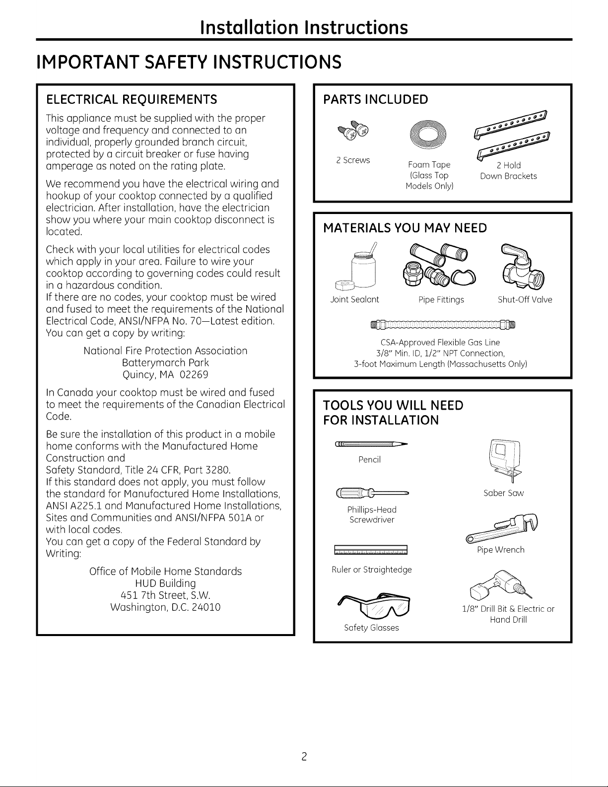
PARTS INCLUDED
2 Screws
Foam Tape
(GlassTop
Models Only)
MATERIALS YOU MAY NEED
Joint Sealant Pipe Fittings
CSA-Approved Flexible Gas Line
3/8" Min. ID, 1/2" NPTConnection,
3-foot Maximum Length (Massachusetts Only)
2 Hold
Down Brackets
Shut-Off Valve
In Canada your cooktop must be wired and fused
to meet the requirements of the Canadian Electrical
Code.
Be sure the installation of this product in a mobile
home conforms with the Manufactured Home
Construction and
Safety Standard, Title 24 CFR,Part 3280.
If this standard does not apply, you must follow
the standard for Manufactured Home Installations,
ANSI A225.1 and Manufactured Home Installations,
Sites and Communities and ANSI/NFPA S01A or
with local codes.
You can get a copy of the Federal Standard by
Writing:
Office of Mobile Home Standards
HUD Building
451 7th Street, S.W.
Washington, D.C. 24010
TOOLS YOU WILL NEED
FOR INSTALLATION
I IIf_( ( _ /,(---]/ ]]
Pencil
Saber Saw
Phillips-Head
Screwdriver
Pipe Wrench
Ruler or Straightedge
1/8" Drill Bit & Electric or
Hand Drill
Safety Glasses
Page 3
Installation Instructions
PRE-INSTALLATION CHECKLIST
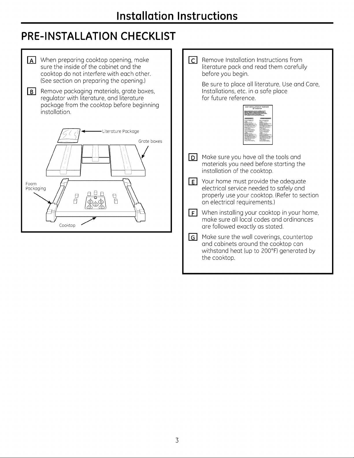
When preparing cooktop opening, make
_3
sure the inside of the cabinet and the
cooktop do not interfere with each other.
(See section on preparing the opening.)
Remove packaging materials, grate boxes,
F_
regulator with literature, and literature
package from the cooktop before beginning
installation.
Foam_ _
Pac _ [_3_ i] _j
Cool<top J
Package
Grate boxes
Remove Installation Instructions from
E1
literature pack and read them carefully
before you begin.
Be sure to place all literature, Use and Care,
Installations, etc. in a safe place
for future reference.
Make sure you have all the tools and
r61
materials you need before starting the
installation of the cooktop.
Your home must provide the adequate
[]
electrical service needed to safely and
properly use your cooktop. (Refer to section
on electrical requirements.)
When installing your cooktop in your home,
FF1
make sure all local codes and ordinances
are followed exactly as stated.
Make sure the wall coverings, countertop
and cabinets around the cooktop can
withstand heat (up to 200°F) generated by
the cooktop.
Page 4
Instollotion Instructions
PREPARING THE OPENING
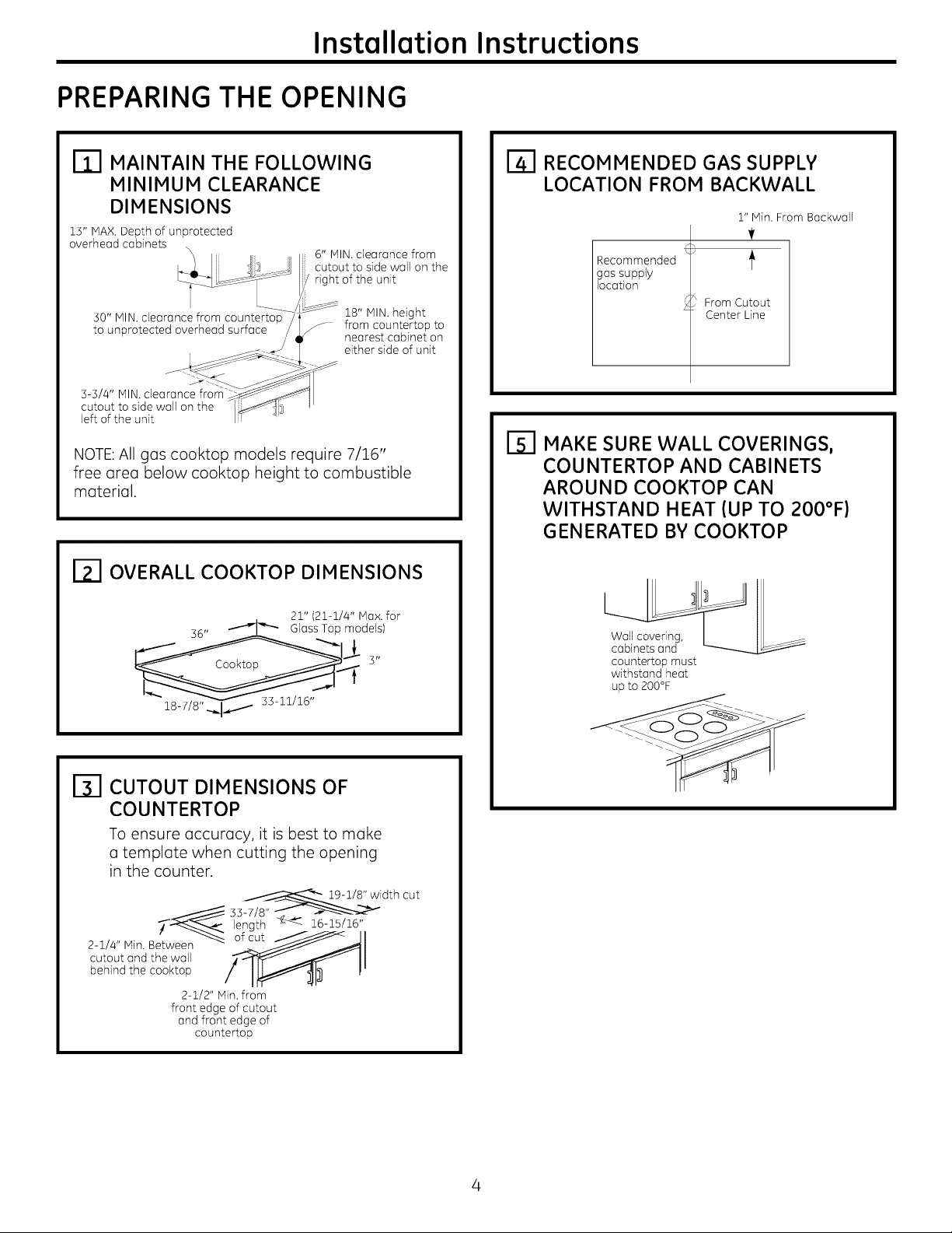
MAINTAIN THE FOLLOWING
MINIMUM CLEARANCE
DIMENSIONS
13" MAX.Depth of unprotected
overhead cabinets
30" MIN. clearance from countertop
to unprotected overhead surface
3-3/4" MIN. clearance from
cutout to side wall on the
left of the unit
\\ 6" MIN. clearance from
cutout to side wall on the
right of the unit
18" MIN. height
from countertop to
nearest cabinet on
either side of unit
NOTE:All gas cooktop models require 7/16"
free area below cooktop height to combustible
material.
I_l OVERALL COOKTOP DIMENSIONS
RECOMMENDED GAS SUPPLY
LOCATION FROM BACKWALL
l" Min. From Backwall
Recommended
gas supply
location
From Cutout
Center Line
F51 MAKE SURE WALL COVERINGS,
COUNTERTOP AND CABINETS
AROUND COOKTOP CAN
WITHSTAND HEAT {UP TO 200°F)
GENERATED BY COOKTOP
21" (21-1/4" IVlax.for
CUTOUT DIMENSIONS OF
COUNTERTOP
To ensure accuracy, it is best to make
a template when cutting the opening
in the counter.
_-1/8 _"width cut
length _ 16-15/16"
2-1/4" Min. B of cutcutout and the wail
behind the cooktop
2-1/2" Min. from
front edge of cutout
and front edge of
countertop
Wall covering,
cabinets and
countertop must
withstand heat
up to 200°F
Page 5
Installation Instructions
INSTALLING THE COOKTOP UNIT
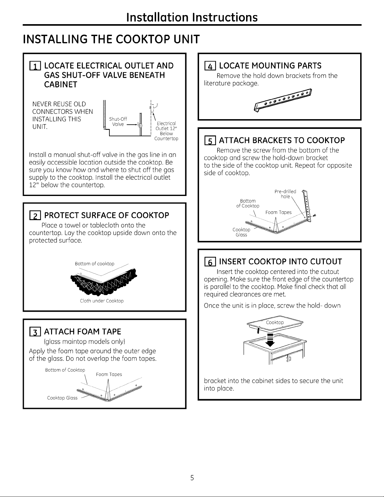
LOCATE ELECTRICAL OUTLET AND
B3
GAS SHUT-OFF VALVE BENEATH
CABINET
LOCATE MOUNTING PARTS
Remove the hold down brackets from the
literature package.
NEVER REUSEOLD
CONNECTORS WHEN
INSTALLING THIS
UNIT.
Install a manual shut-off valve in the gas line in an
easily accessible location outside the cooktop. Be
sure you know how and where to shut off the gas
supply to the cooktop. Install the electrical outlet
12" below the countertop.
H I
shutoff11i\
_L Valve r_ I Electrical
J_J
U
II Outlet 12"
I Below
Countertop
_-I PROTECT SURFACE OF COOKTOP
Place a towel or tablecloth onto the
countertop. Lay the cooktop upside down onto the
protected surface.
Bottom of cooktop
Cloth under Cooktop
_-I ATTACH BRACKETS TO COOKTOP
Remove the screw from the bottom of the
cooktop and screw the hold-down bracket
to the side of the cooktop unit. Repeat for opposite
side of cooktop.
Pre-drilled
Bottom
of Cooktop
.\.._ Foem Topes
Cooktop
Gloss
I-_ INSERT COOKTOP INTO CUTOUT
Insert the cooktop centered into the cutout
opening. Make sure the front edge of the countertop
is parallel to the cooktop. Make final check that all
required clearances are met.
Once the unit is in place, screw the hold- down
[_] ATTACH FOAM TAPE
(glass maintop models only)
Apply the foam tape around the outer edge
of the glass. Do not overlap the foam tapes.
Bottom of Cooktop
\ Foam Topes
\
Cooktop Gloss
bracket into the cabinet sides to secure the unit
into place.
Page 6
Installation Instructions
INSTALLATION--GAS CONNECTIONS
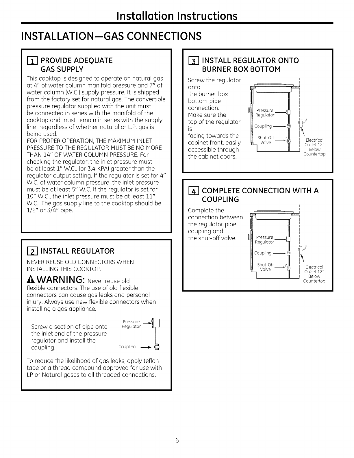
PROVIDE ADEQUATE
GAS SUPPLY
This cooktop is designed to operate on natural gas
at 4" of water column manifold pressure and 7" of
water column (W.C.) supply pressure. It is shipped
from the factory set for natural gas. The convertible
pressure regulator supplied with the unit must
be connected in series with the manifold of the
cooktop and must remain in series with the supply
line regardless of whether natural or L.P.gas is
being used.
FOR PROPEROPERATION, THE MAXIMUM INLET
PRESSURETO THE REGULATOR MUST BE NO MORE
THAN 14" OF WATER COLUMN PRESSURE.For
checking the regulator, the inlet pressure must
be at least 1" W.C.. (or 3.4 KPA) greater than the
regulator output setting. If the regulator is set for 4"
W.C. of water column pressure, the inlet pressure
must be at least 5" W.C. If the regulator is set for
10" W.C., the inlet pressure must be at least 11"
W.C.. The gas supply line to the cooktop should be
1/2" or 3/4" pipe.
_-I INSTALL REGULATOR
NEVER REUSEOLD CONNECTORS WHEN
INSTALLING THIS COOKTOP.
-A WARNING: Neverreuseold
flexible connectors. The use of old flexible
connectors can cause gas leaks and personal
injury. Always use new flexible connectors when
installing u gas appliance.
INSTALL REGULATOR ONTO
BURNER BOX BOTTOM
Screw the regulator
onto
the burner box
bottom pipe
connection.
Make sure the
top of the regulator
is
facing towards the
Pressure __._
Regulator
Coupling --I
Shut-Off
cabinet front, easily
accessible through
Valve
the cabinet doors.
COMPLETE CONNECTION WITH A
COUPLING
Complete the
connection between
the regulator pipe
coupling and
the shut-off valve.
Pressure
Regulator
Coupling --_
Shut-Off _:
Valve --'_
I
I
LI
i\
II Electrical
I Outlet 12"
I Below
Countertop
I
I
U
II Electrical
I Outlet 12"
I Below
Countertop
Pressure _l
Screw a section of pipe onto
the inlet end of the pressure
regulator and install the
coupling.
Regulator
Coupling _
To reduce the likelihood of gas leaks, apply teflon
tape or a thread compound approved for use with
LP or Natural gases to all threaded connections.
Page 7
Installation Instructions
CHECK FOR LEAKS
Before testing for leaks, make sure oll burner knobs
ore in the OFF position.
After connecting the cooktop to gas, check system
for leaks with o manometer. If a manometer is not
available, turn the gas supply on to the cooktop
and use o liquid leak detector at oil joints and
connections to check for leaks.
Tighten oil connections if necessary to prevent gas
leakage in the cooktop or supply line.
DO NOT USE OPEN FLAME TO CHECK FOR
LEAKS!
Disconnect the cooktop and its individual shut-off
valve from the gas supply piping system during any
pressure testing of that system at test pressures
greater than 1/2 psig (3.5 kPa).
Isolate the cooktop from the gas supply piping
system by closing its individual shut-off valve
during any pressure testing of the gas supply
system at test pressures equal to or less than
1/2 psig (3.5 kPa).
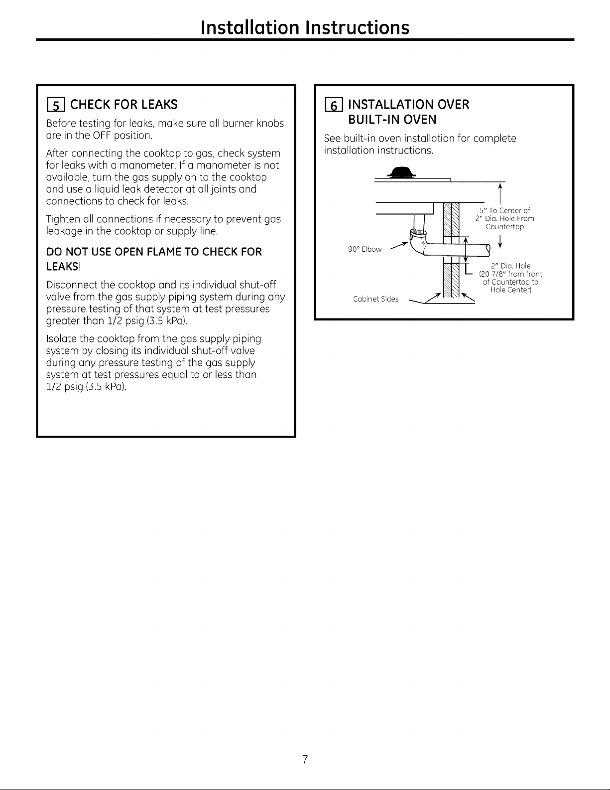
INSTALLATION OVER
BUILT-IN OVEN
See built-in oven installation for complete
installation instructions.
I
T
I _ s,,ToCenterof
| I _] 2" Dia. Hole From
_ _ Countertop
90 ° Elbow ........ I ---'_--
(20 7/8" from front
Cabinet Sides
7 _1"_ 2"Dia.Hole
of Countertop to
Hole Center}
Page 8
Installation Instructions
INSTALLATION--ELECTRICAL CONNECTIONS
_AWARNING - Disconnectoilelectricol
power ot the moin circuit breoker or fuse box
before instolling.
EXTENSION CORDS
Because of potential safety hazords under certoin
conditions, we strongly recommend against the
use of an extension cord. However, if you still
elect to use an extension cord, it is absolutely
necessary that it be a UL listed B-wire grounding
type applionce extension cord ond thot the
current carrying rating of the cord in amperes be
equivalent to or greoter than the branch circuit
roting. Such extension cords ore obtoinoble
through your Iocol opplionce deoler.
IMPORTANT: (Pleosereod corefully)FOR
PERSONAL SAFETY,THIS APPLIANCE MUST BE
PROPERLY GROUNDED.
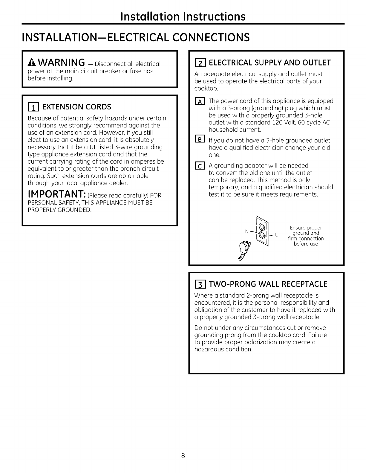
ELECTRICAL SUPPLY AND OUTLET
An odequote electricol supply ond outlet must
be used to operote the electricol ports of your
cooktop.
The power cord of this applionce is equipped
with o 3-prong (grounding) plug which must
be used with o properly grounded 3-hole
outlet with u standard 120 Volt, 60 cycle AC
household current.
If you do not hove o 3-hole grounded outlet,
hove o quolified electricion chonge your old
one.
A grounding odoptor will be needed
to convert the old one until the outlet
con be reploced. This method is only
temporary, ond o qualified electrician should
test it to be sure it meets requirements.
Ensure proper
L ground ond
firmconnection
beforeuse
TWO-PRONG WALL RECEPTACLE
Where a standard 2-prong wall receptacle is
encountered, it is the personal responsibility and
obligation of the customer to hove it replaced with
u properly grounded B-prong wall receptacle.
Do not under any circumstonces cut or remove
grounding prong from the cooktop cord. Failure
to provide proper polarization may create u
hazardous condition.
Page 9
Installation Instructions
USAGE SITUATIONS WHERE
APPLIANCE POWER CORD
WILL BE DISCONNECTED
INFREQUENTLY
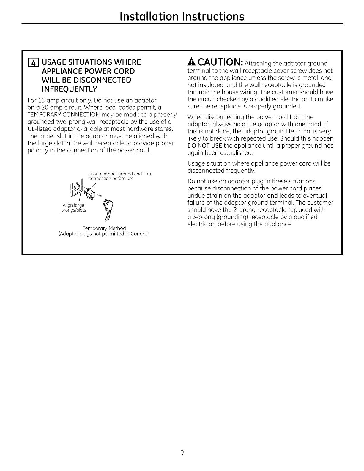
For 15 amp circuit only. Do not use an adaptor
on a 20 amp circuit. Where local codes permit, a
TEMPORARY CONNECTION may be made to a properly
grounded two-prong wall receptacle by the use of a
UL-listed adaptor available at most hardware stores.
The larger slot in the adaptor must be aligned with
the large slot in the wall receptacle to provide proper
polarity in the connection of the power cord.
Ensure proper ground and firm
_. connection before use
prongs/slots
Alignlarge
(Adaptor plugs not permitted in Canada)
Temporary Method
-ACAUTION: Attachingthe adaptor ground
terminaltothe wallreceptaclecoverscrew does not
ground the applianceunlessthescrew ismetal,and
notinsulated,and the wallreceptacleisgrounded
through the house wiring.The customer should have
the circuitchecked by a qualifiedelectriciantomake
surethe receptacleisproperlygrounded.
When disconnecting the power cord from the
adaptor, always hold the adaptor with one hand. If
this is not done, the adaptor ground terminal is very
likely to break with repeated use. Should this happen,
DO NOT USE the appliance until a proper ground has
again been established.
Usage situation where appliance power cord will be
disconnected frequently.
Do not use an adaptor plug in these situations
because disconnection of the power cord places
undue strain on the adaptor and leads to eventual
failure of the adaptor ground terminal. The customer
should have the 2-prong receptacle replaced with
a 3-prong (grounding) receptacle by a qualified
electrician before using the appliance.
Page 10
Installation Instructions
COOKTOP BURNERS
ASSEMBLING THE COOKTOP
BURNERS
The electrode of the spark igniter is exposed. Be
careful not to push any cooktop controls while the
top of the burner is removed.
Do not remove the top or touch the electrode
of any burner while another burner is turned on.
Electrical shock might result.
Reploce the burner head onto the burner
bose, making sure that the heod is properly
oriented over the burner bose ond the
electrode. Moke sure to place
the correct burner head on the correct burner
bose and thor the burner head sits level on
the burner bose. The burner heads ore not
interchongeoble.
Place the burner
[]
cops on the burner
heads, making sure
to place the correct
burner cop on the
correct burner
head. The burner
cops ore not
interchangeable.
Make sure that the
burner cops ore
properly seated on
the burner heads.
Burner cop properly seoted
Burner cop not properly seoted
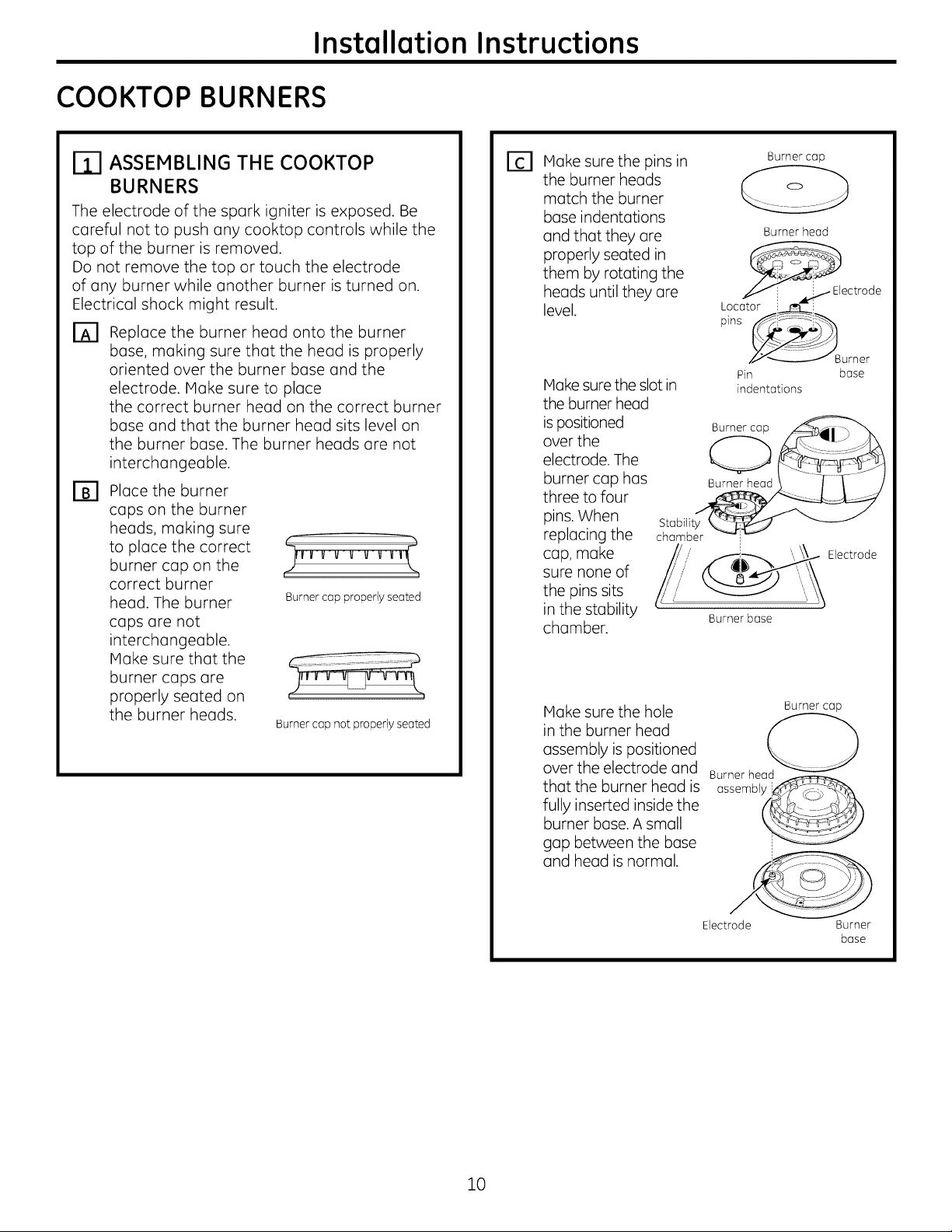
Make sure the pins in
[]
the burner heads
match the burner
bose indentutions
und that they ore
properly seated in
them by rotating the
heuds until they ore
level.
Make sure the slot in
the burner head
is positioned
over the
electrode. The
burner cup has
three to four
pins. When
replucing the
cup, make
sure none of
the pins sits
in the stability
chamber.
Make sure the hole Burner cop
in the burner head
assembly is positioned
over the electrode and Burner head
that the burner heod is ossembly_r_-_]b,
fully inserted inside the
burner bose. A small
gop between the bose
and head is normal.
Stabilit_
chamber _
_ectrode
__Burner
Pin base
indentations
Burnerbase
Burner cop
Burner heod
Electrode
10
Electrode Burner
bose
Page 11

Installation Instructions
[_ CHECK IGNITERS
Operation of the electric igniters should be
checked after the cooktop and supply line have
been carefully checked for leaks and the cooktop
has been connected to the electrical power.
On models so equipped, check to be sure the
cooktop is in the UNLOCKED position.
r_ Push and turn a burner valve to the LITE
position. All spark igniters will make a series of
sparks (ticking sounds), but only the burner
turned to LITE will light.
• The burner should light when gas is
available to the burner.
• Once the burner lights, it should be turned
out of the LITE position.
r_ Try each valve separately until all burners
have been checked.
_-I BURNER IGNITION
THE BURNER FLAMES
Turn each burner on. Flames should be blue in color
with no trace of yellow. The burner flames should
not flutter or blow away from the burner. The flame
should be no less than 1/4" on the lowest setting
and no greater than 1-1/2" on highest setting.
-&WARNING: ,fyouattempt to measure
the flame, please use caution.
Burns could result.
Cooktop Burner
Burners should be checked frequently
Cooktop Spark Ignition-When you turn the
cooktop knob to LITE,the spark igniter makes u
series of electric sparks (ticking sounds) which light
the burner. During a power failure, the burners will
not light automatically. In an emergency, a cooktop
burner may be lit with a match by following the
steps below.
-&WARNING: Lighting gas burners with a
match is dangerous. You should match light the
cooktop burners only in an emergency.
On models so equipped, check to be sure the
cooktop is in the UNLOCKED position.
r-_ Light a match and hold the flame near the
burner you want to light. Wooden matches
work best.
r_ Push in and turn the control knob slowly. Be
sure you are turning the correct knob for the
burner you are lighting.
NOTE: If the burner does not light within five seconds,
turn the knob off and wait one minute before trying
again.
I-_ BURNER GRATES
The three cooktop grates are designed for
specific positions. For maximum stability, these
grates should only be used in their proper position:
they should not be interchanged. For your
convenience, the undersides of the left and right
grates are marked "OUTSIDE" and "INSIDE". Make
sure that the side marked "OUTSIDE" is on the outer
edge of your cooktop. Make sure that the tubs
on either side of the center grate fit into the slots
located on the "INSIDE" edge
of the side grates.
"INSIDE"
edges
"OUTSIDE.... OUTSIDE"
edge edge
Tab Tab
11
Page 12

Installation Instructions
OPERATION CHECKLIST
Hake sure all controls are left in the OFF
position. Check to be sure the cooktop is in the
UNLOCKED position (on models so equipped).
Hake sure the flow of air to and from the
cooktop is unobstructed.
The serial plate for your cooktop is located on
the bottom of the burner box. In addition to the
model and serial numbers, it tells you the ratings
of the burners and the type of fuel and pressure
the cooktop was adjusted for when it left the
factory.
When ordering parts, always include the serial
@
number, model number and a code letter to
ensure proper replacement parts.
Recheck Steps:
RI
Double check to make sure everything
in this guide has been completed. Rechecking
steps will ensure safe use of the cooktop.
12
Page 13

Installation Instructions
MAKING THE LP CONVERSION
If sold outside the U.S.and Canada:
-& WARNING: ,fyouwish to use this product
with Liquefied Petroleum (LP)gas containing greater
than 10% butane, you must purchase a butane
conversion kit. To order,
please call 1.888.664.8403 or 1.787.276.4051.
Model ButGne Kit #
JGP970 WB28T10229
ZGU36 WB28T10229
JGP975 WB28T10231
JGP963 WB28T10233
JGP630 WB28T10235
JGP628 WB28T10236
r_ SAFETY INFORMATION YOU
SHOULD KNOW
The pressure regulator and burner orifices (]re set
for natural gas. To use LP gas, the regulator and
burner orifices must be converted. The LP orifice
spuds for the cooktop burners can be located in the
literature package attached to the regulator.
--&CAUTION: The cooktop, as shipped from
the factory, is set for use with natural gas. If you
wish to use your cooktop with LP gas, you must
first replace the orifices and convert the pressure
regulator.
-&WARNING: This conversion must
be performed by a qualified installer or gas supplier
in (]ccordance with the manufacturer's instructions
and all codes and requirements of the authority
having jurisdiction. Failure to follow instructions could
result in serious injury or property damage. The
qualified agency performing this work assumes
responsibility for the conversion.
--&CAUTION: The following adjustments
must be mode before turning on the burner.
Failure to do so could result in serious injury. Be
sure pressure regulator has been converted as
described in Step 2.
TOOLS YOU WILL NEED
FOR LP CONVERSION
Phillips-Head
Screwdriver
Pliers
Safety Glasses
7mm Nutdriver
No. 15 Torx-Head
Driver
Small Flat-Head
Screwdriver (4mm or
5/32" tip size, 60mm
long)
ADJUST YOUR COOKTOP FOR USE
WITH LP GAS
Disconnect oll electrical power, ot the moin
circuit breaker or fuse box.
Shut off the gas supply to the cooktop
by closing the manual shut-off valve.
Adjust the pressure regulator, by the following
[]
instructions:
• Unscrew the cop.
• Ploce your thumb ogoinst the flot side of the
spring retoiner ond press down to remove
the retoiner.
• Carefully look at the spring retainer to locate
the NAT or LP position.
Cop Gosket
/ I---- Spring
/ _ L_JPropone
Position
NAT. Position
13
Pressure Regulator
• Turn the spring retoiner over so thot
LP is showing on the bottom.
• Snap the retainer buck into position.
• Screw the cup buck onto the regulator.
Page 14

Installation Instructions
MAKING THE LP CONVERSION (CONT.)
CHANGE COOKTOP BURNER
ORIFICES
Remove the top grates,
burner cops, and burner
heads.
Remove the spark
igniters from the burner
bose (if required to
access the orifices).
Using o No. 15 "Torx"
head driver bit, remove
the screws holding the
burner bose in position.
Using u 7mm nut driver,
remove the top burner
orifices. These may be
accessed through the
hole in the cooktop.
Orifice Spud Located
Through This Opening
emove This
Assembly
Burner cap
CHANGE COOKTOP BURNER
ORIFICES (CONT.)
NOTE: On most burners,
the orifices hove o spring- Retainer
loaded retaining ring Ground Ring
the hex head to hold the
orifice in the nut driver during
installation and removal. A
slight amount of force is required to push the nut
driver down over the ring.
18,000 BTUBurner
Ion some models)
_Burner
Burner @head
base
Spark igniter
Burner
cop
14
Page 15

Installation Instructions
CHANGE COOKTOP BURNER
ORIFICES {CONT.)
Locate the LP/Propmne orifices shipped
inside the literature package. They
will have a digit number and the letter "L" on
the side. (Important: Save the orifices
removed from the appliance
for future use.)
Each orifice will show a series of engraved
marks, (I, II, III, X or none),
located on the top.
These marks denote the precise location of each
orifice to the cooktop burner.
OOOO
18,000 BTU/HR Burner (onsome models)
O he 18,000 BTU/HRburner has two orifices with
markings located in the sides only. (Seerating
plate on bottom of appliance).
Units with 4 burners
Units with 5 burners
NOTE: The main orifice is located low in the center
of the burner while the simmer orifice is located
higher behind the center of the burner.
Soirifmicmer_
Main orifice
Left Front Right Front
Model Orifice Orifice
JGP630 II III
JGP963 III X
JGP970
ZGU36K
JGP975 III Moin 206X N-_ 108X L
Simmer 57N -_ 34L
Install the LP/Propune orifices in their precise
[]
locutions us noted in the illustrations above.
Return the natural gas orifices to the bracket
[]
and reattach the bracket and
the instruction sheet to the pressure regulator
using the screw removed previously.
Replace the burner bases, heads, cups and
[]
top grates. (NOTE: When re-uttuchinq the
burner buses to qluss top units, tiqhten screws
to u maximum of
10 in.-Ibs torque.)
Reploce: With:
15
Page 16

Installation Instructions
MAKING THE LP CONVERSION (CONT.)
ADJUST BURNER FLAMES
Turn all burners full on and check the flames.
They should be blue in color with some yellow
tipping at the ends of the flame. Foreign
particles in the gas line may cause an orange
flame at first, but this will soon disappear.
NOTE: For the 18,000 BTU/HR burner (on some
models) the cooktop burner knob should be
turned to the setting before the lowest setting.
This will ensure that the entire burner is
operating.
r_ Turn the cooktop burner knob to the lowest
setting while observing the flame.
Adjust the low flame setting using the valve bypass
screw as follows:
Low-setting adjustments must be made with two
other burners in operation on a medium setting.
This prevents the low flame from being set too low,
resulting in the flame being extinguished when
other burners are turned on.
E] To adjust the flame, remove the knobs. Insert
a screwdriver through the access hole in valve
adjustment screw in
valve. Refer to the
illustration below that I
switch. Engage
matches the adjustment
screw location for your
model.
If the flames were too
small or fluttered, open
the valve more than
the original setting.
If the flames blew
away from the burner,
close the valve more
than the original
setting.
Kburner
/only
r-_ Make the adjustment by slowly turning the
screw until flame appearance is correct.
Note: Some models may contain a siliconeshieldwhich
coversthe valve switch and access hole.A flashlight may
be requiredto locate the access hole.To accessthe valve
adjusting screw,push the screwdriver through this shield.
After adjustment, reseat the shield around the switch hub
with your fingers, afterwithdrawing the screwdriver.
Reseat silicone shield
CORRECT INCORRECT
r_ Testing Flame Stability:
Test 1 - Turn the knob from "HI" to the lowest
setting quickly. If the flame goes out
at the lowest setting, increase the
flame size and test again.
Test 2 -
rF1 Flame Recheck:
After the adjustment is made, turn all burners off.
Ignite each burner individually. Observe the flame
at the "HI" position. Rotate the valve to the lowest
setting and be sure that the flame size decreases
as the valve is rotated counterclockwise.
TO CONVERT THE COOKTOP BACK TO NATURAL
GAS, REVERSETHE STEPS UNDER MAKING THE LP
CONVERSION.
Once the conversion is complete and checked
ok, fill out the LP sticker and include your name,
organization and date conversion was made. Apply
the sticker near the cooktop gas inlet opening to
alert others in the future that this appliance has
been converted to LP gas. If converting back to
natural gas from LP, please remove the sticker so
others know the appliance is set to use natural gas.
With the burner on the lowest setting,
open and close the cabinet door
under the cooktop. If the flame is
extinguished by the air currents
created by the door movement,
increase the flume height and test
again.
16
Page 17

Instructions
Table de cuisson scell
d'installation
I P-1 Questions? Appelez le Centre de r_ponse 1.800.561.3344 ou visitez notre site
AVANT DE COMMENCER
Avant de commencer, lisez attentivement la totalit6
de ces instructions.
•IMPORTANT - Conservezces
instructionspourvotreinspecteurlocal
•IMPORTANT - mespectez toutesles
ordonnances et lescodes locoux.
• Note c_l'installateur- Assurez-vousde laissezces
instructionsau consommateur.
• Note au consommateur - Conservez ces
instructionspour r6f6rencefuture.
• Lo garantiene couvre aucune panne due c_une
mauvaise installation.
.AAVERTISSEMENT -
Cet appareil doit @trebien mis (_la terre.
•IMPORTANT -vousdevez
verifierque cetoppareiln'aitpos de fuite
conform6ment aux instructionsdu fabricant.
• L'installateur est responsable d'une bonne
installation et Io gorontie ne couvre aucune
panne due (_une mauvaise installation.
-AAV ERTISSEM ENT - D6brancheztout
couront61ectriqueou niveou du disjoncteurde Io
maison ou de la boTtec_fusiblesavant d'installer.
Web 8 I'adresse ' www.electromenagersge.ca
au gaz de 91 cm (36")
JGP628, JGP630, JGP963, JGP970,
JGP975, ZGU36
POUR VOTRE SI_CURITI_
-_ AVERTISSEMENT -
Si vous ne suivez pas exactement les instructions
de ce manuel, vous risquez d'occasionner un
incendie, une explosion
ou une fuite de gaz, qui peuvent provoquer des
dommages mat6riels, des blessures corporelles ou
la mort.
Ne conservez pos ou n'utilisezjomais d'essence
ou d'autres liquides ou vapeurs inflammables (_
proximit6 de cet appareil
ou de tout autre appareil m6naged
CI QUE VOUS DEVEZ FAIRE SI
VOUS SENTEZ LE GAZ :
• N'essoyezjomois d'ollumer un opporeil
61ectrom6nager. Ne touchez (_aucun
commutoteur d'61ectricit6, n'utilisez jamais un
t616phone dons votre b(_timent.
• Appelez imm6diatement votre fournisseur de
goz (_I'oide du t616phone d'un voisin. Suivez les
instructions de votre fournisseur de goz.
• Sivous ne pouvez pos entrer en contact avec
votre fournisseur de goz, appelez
les pompiers.
L'installation et le service de votre table de cuisson
doivent @trefoits par un installateur qualifi6, un
technicien de service ou votre fournisseur de gaz.
I
31-10612-4 (lO-lO GE) 1
Page 18

Instructions d'installation
INSTRUCTIONS IMPORTANTES DE SI CURITI
La conception de votre table de cuisson a 6t6
approuv6 par I'ACNOR International. Vous trouverez
des pr6cautions _]prendre en mati_re de s6curit6
dans votre Guide d'utilisation et de soins. Lisez-les
attentivement.
• L'installation de votre table de cuisson
doit se conformer aux codes Iocaux ou, en
I'absence de codes Iocaux, au National Fuel Gas
Code, ANSI Z22E1/NFPA 54 Derni_re 6dition.
• Assurez-vous que votre table de cuisson soit
bien install6e par un installateur qualifi6 ou un
technicien de service.
• Pour 61iminer tout mouvement corporel
au dessus des brOleurs de votre table de cuisson,
6vitez de placer des armoires de cuisine au
dessus des brOleurs.
• N'installezjamais votre appareil pros d'une porte
d'entr6e ou dans un emplacement o0 un courant
d'air peut g@ner son usage.
PII_CES COMPRISES
2 vis
Bandes de mousse (Pour 2 Supports de fixation
les modules 6 surface en
verre seulement)
MATI_RIAUX DONT VOUS POUVEZ
AVOIR BESOIN
Agent de scellement Raccords de tuyaux Robinet d'alimentation
de tuyau de gaz
Raccord flexible de gaz approuv_ par I'ACNOR
DI min 3/8", Jonction NPT 1/2
BESOINS D'I_LECTRICITI_
Cet appareil m6nager doit _tre livr6 avec le ban
voltage et la bonne fr6quence et branch6 (_son
propre circuit de d6rivation bien mis 6 la terre,
prot6g6 par un disjoncteur ou un fusible qui ant
I'amp@age not6 sur la plaque min6ralogique de
votre appareil.
Nous vous recommandons de faire brancher le
ceblage 61ectrique et la fiche de votre cuisini_re
par un 61ectricien qualifi& Apr6s I'installation,
demandez 6 1'61ectricien de vous montrer
I'emplacement de votre coupe-circuit principal.
Demandez _]votre entreprise de services publics les
codes 61ectriques en vigueur
dans votre r6gion. En ne cOblant pas votre
cuisini_re conform6ment aux codes en vigueur,
vous provoquez une situation dangereuse. En
I'absence de codes, vous devez c0bler et isoler
votre cuisini_re conform6ment aux exigences du
Canadian Electrical Code.
OUTILS DONT VOUS AUREZ BESOINS
Crayon
Sciesauteuse
Tournevis Phillips
R@gle ordinaire ou de
v@ification
Perceuse 6 main ou _lectrique
Lunettes de s@curit@
CI@6 tuyau
et foret de 1/8po
Page 19

Instructions d'lnstallation
LISTE DEVITRIFICATION AVANT INSTALLATION
Pour pr6parer I'ouverture de la surface de
_3
cuisson, vous devez vous assurer que
I'int6rieur de I'armoire ne touche pas la table
de cuisson (consultez la section sur la
pr6paration de I'ouverture).
Enlevez les mat6riaux d'emballage, les
r_
boTtes de grille, le r6gulateur avec sa
documentation et la documentation de
votre table de cuisson avant de commencer
6 I'installer.
_1_ Documentation
2ballage_
de/
Table
cuisson
Bottes de
grille
Enlevez les instructions d'installation de la
E1
trousse de documentation et lisez-les
soigneusement avant de commencer.
Assurez-vous de bien ranger toute la
documentation, le manuel d'utilisation et
d'entretien, etc. duns un endroit sOr pour
r6f6rence future.
Assurez-vous d'avoir tousles outils et tous
F61
les mat6raux n6cessaires avant de
commencer 6 installer votre table de
cuisson.
rE1 Votre maison dolt @trealiment6e en courant
61ectrique ad6quat pour vous permettre de
bien utiliser en toute s6curit6 votre table de
cuisson. (Consultez la section sur les besoins
d'61ectricit&)
r_ Pour installer votre table de cuisson dans
votre maison, assurez-vous de vous
conformer scrupuleusement 6 tous les
codes et 6 toutes les ordonnances locales.
Assurez-vous que les rev@tements
[]
de mur, le comptoir et les armoires autour
de la table de cuisson puissent supporter la
chaleur [pouvant atteindre 93°C (200°F)]
produite par la table de cuisson.
Page 20

Instructions d'lnstallation
PREPARATION
DE L°OUVERTURE
VOUS DEVEZ RESPECTER LES
DEGAGEMENTS MINIMAUX
SUIVANT
Profondeur max de 33 cm (13") des
armoires en surplomb non prot6g6es D6gagement min. de 15
D6gagement min. de 76 cm (30") du
comptoir 6 la surface en non surplomb
non prot6g6es
D6gagement min
de 10 cm (3-3/4") du
d6coupage au tour de
c6t6 droite de I'appareil
cm (6") d6coupage au
mur de c6t6 6 droite de
I'appareil
Hauteur min
de 45 cm (18")
du comptoir
6 I'armoire la
plus proche de
chaque c6t6 de
I'appareil
REMARQUE : tous les mod61es de surface
6 cuisson au gaz requi6rent un d6gagement
de 1,1 cm (7/16 po) sous la hauteur de la surface
pour la mati6re combustible.
I_l DIMENSIONS DU DI_COUPAGE DE
LA TABLE DE CUISSON
91 cm (56") "'"_1 "_'_ max. pour table de cuisson en
55 cm (21")(54,6 cm [21-1/2"]
verre)
EMPLACEMENT RECOMMA.NDE_ DE
L'ALIMENTATION DE GAZ A
PARTIR DU MUR ARRII_RE
2,5 cm (1") min. du mur arri_re
Emplacement
recommand6 de
ralimentatbn Du
de gaz _ d6coupage 6
la ligne
du centre
F51 ASSUREZ-VOUS OUE LES
REVF:TEMENTS MUR, LE
COMPTOIR ET LES ARMOIRES
AUTOUR DE LA TABLE DE
CUISSON PUISSENT SUPPORTER
LA CHALEUR (POUVANT
ATTEINDRE 93°C [200°F])
_'_ 8 cm (S')
48 cm (18-7/8") ..,,..I_,...-'--_
DIMENSIONS TOTALES DE LA
TABLE DE CUISSON
Pour assurer lajustesse du d6coupage,
il vaut mieux faire un gabarit pour couper
I'ouverture dans le comptoir.
86 cm (33-7/8 po)Iongueur
du d6coupage _ Largeur du d6coupage
_,5 cm_9- i/8")
! _--_.__-'--_ _ (16-15/16,,)
°(stancem(nde5,7cm _.-__J_l I
(2-1/4") de d6coupage au _'_i_r -_ _ I
murderrierelatablede / I_il)l _'
CUlSSOR " liT _I--
6,4 cm (2-i/2") Distance min.
de l'ar#te avant du d#coupage
de l'arr#te avant de la table de
cuisson
Les rev#tements de
mur, les armoires et
le comptoir doivent
pouvoir supporter
une chaleru pouvant
atteindre 93°C (200°F)
Page 21

Instructions d'lnstallation
INSTALLATION DE LA TABLE DE CUISSON
PLACEZ LA PRISE
D'ALIMENTATION
I_LECTRIOUE ET LE ROBINET
D'ALIMENTATION DE GAZ
AU-DESSOUS DE L'ARMOIRE
N'UTILISEZ JAMAIS. DES _j_
RACCORDS USAGES i,
APPARElL. Isocm112")
POUR INSTALLER CET d_mentation !_ IPrse6ectrque
Montez le robinet d'alimentation manuel sur le
tuyau de gaz _]un emplacement facile _]atteindre
en dehors de la table de cuisson. Assurez-vous de
savoir o0 et comment couper I'alimentation de gaz
_]la table de cuisson. Montez la prise 61ectrique 30
cm (12") au-dessous du comptoir.
H I
Rodinetd'arr@t 11 IF'\
isouslecomptoir
PROTI_GEZ LA SURFACE DE LA
TABLE DE CUISSON
Placez une serviette ou un torchon sur le comptoir.
Posez la table de cuisson _]I'envers sur la surface
prot6g6e.
Envers de la table de cuisson
Linge sous la table de cuisson
/
ATTACHEZLA BANDEDE MOUSSE
(modUlesdela table de verre seulement)
Appliquez la bande de mousse autour du bard
ext6rieur du verre. Ne superposez pas les bandes
de mousse.
TROUVEZ LES PII_CES DE
MONTAGE
Retirez les supports de fixation de la trousse de
documentation.
FIXEZ LES SUPPORTS DE FIXATION
#, LA TABLE DE CUISSON
Enlevez la vis d'un c6t6 de la table de cuisson,
vissez un support de fixation _] un c6t6 de la table
de cuisson. R6p6tez la m@me op6ration de I'autre
c6t6 de la table de cuisson.
Support de
fixation
Bas de latablede
cuisson Bandes de
mousse .............--
Verre de la table
de cussion
INSI_REZ LA TABLE
DE CUISSON DANS L'OUVERTURE
DI_COUPI_E
Ins6rez la table de cuisson centr6e dans I'ouverture
d6coup6e. Assurez-vous que I'arr@te de devant
du comptoir salt bien parall@le _]I'extr6mit6 de la
surface de cuisson. Faites une v6rification finale
pour vous assurer de bien respecter tousles
d6gagements.
I
\
Bas de latable
de cuisson Bandes de
Verre de latabl
de cuisson
mousse .
Une fois la table de cuisson en place,
vissez les supports de fixation aux c6t6s de
I'armoire pour tenir la table de cuisson bien en
place.
Page 22

Instructions d'installation
INSTALLATION--BRANCHEMENT DU GAZ
ITI FOURNISSEZ UN BaN
APPROVISIONNEMENT EN GAZ
Cette table de cuisson est congue pour fonctionner au
gaz nuturel (_une pression de tubulure d'admission
de 4 po. de colonne d'eau et (_une pression
d'upprovisionnement de 7 po. de colonne d'eau. Elle
est exp6di6e de I'usine r6gl6e pour le gaz nuturel.
Le r6gulateur de pression convertible fourni avec
I'appareil doit _tre branch6 en s6rie (_lu tubulure
d'udmission de la table de cuisson et doit rester
branch6 sur lu ligne d'approvisionnement qu'il
s'agisse de gaz nuturel ou de gaz propane (LP).POUR
OBTENIR UN BaN FONCTIONNEMENT,
LA PRESSIONIVlAXIIVlALED'ENTRI_EAU RI_GULATEUR
NEDOlT PAS I_TRESUPI_RIEUREA 14 po. DE COLONNE
D'EAU.Pour v6rifier le r6gulateur, lu pression d'entr6e
doit _tre au mains de 1 po. de colonne d'eau (ou 3,4
KPA)plus grande que celle de r6glage de sortie du
r6gulateur. Si le r6gulateur est r6g16(_une pression de
4 po. de colonne d'eau, la pression d'entr6e doit _tre
au mains 6gale (_5 po. Si le r6gulateur est r6g16 (_une
pression de 10 po., la pression d'entr6e doit _tre au
mains 6gale (_11 po. La ligne d'approvisionnement
de gaz (_la table de cuisson doit _tre un tuyau
de 1/2 po. ou de 3/4 po.
INSTALLEZ LE RI_GULATEUR EN
BAS DE LA BO/TE DE BRULEURS
Vissezle r6gulateur dans
le raccord du bas de
la boTtede br01eurs.
Assurez-vous que le
haut du r6gulateur
soit face (_I'avant
de I'armoire, et
soit facilement
accessible 6 partir
des portes de
I'armoire.
R6gulateur
de pression _
Raccord
Robinet --I
d'arr_t
I
I
LI
i\
Iiprise61ectrique
I 12 po.
lau-dessous du
comptoir
TERMINEZ LE RACCORDEMENT
AVEC UN RACCORD
Terminez le raccordement entre le raccord du
tuyau du r6gulateur ,
et le robinet d'arr@t. ' _
_1 INSTALLEZ LE RI_GULATEUR
N'utilisezjamais de vieux raccords quand vous
installez votre table de cuisson..
AVERTISSEMENT :
N'utilisezjamais des raccords flexibles usag6s.
L'utilisation de raccords flexibles usag6s peut
occasionner des fuites de gazet des blessures
corporelles. Utilisez toujours des raccords flexibles
neufs quand vous installez un appareil (_gaz.
vissez une section du tuyau clans R6gulateurde___ I
I'extr6mit6 d'entr6e du r6gulateur press_on
de pression et installez le
raccord. Raccord
Pour r6duire la possibilit6 de fuites de gaz, posez un
ruban de t6flon ou mettez de la graisse pour filetage
approuv6e pour le gaz naturel ou butane sur tousles
raccords filet6s.
R6gulateur
de pression ._
Raccord --
Robinet ---d
d'arr@t
LI
i\
IiPrise61ectrique
I 12 po.
lau-dessous du
comptoir
Page 23

Instructions d'installation
VI_RIFIEZ QU°IL N'Y A PAS
DE FUITE
Avant de v6rifier qu'il n'y a pas de fuite, assurez-
vous que tousles boutons de brGleurs soient en
position OFF (arr#t).
Apr6s avoir branch6 la table de cuisson au gaz,
v6rifiez qu'il n'y a pas de fuite dans le syst6me
(_I'aide d'un manom_tre. Si vous n'avez pas de
manom_tre, ouvrez I'approvisionnement de guz (_
la table de cuisson et utilisez un d6tecteur de fuite
liquide (_tousles raccords etjoints pour trouver les
fuites.
Resserrez tousles raccords le cas 6ch6ant pour
arr@ter les fuites de gaz de la table de cuisson ou
de la ligne d'approvisionnement.
N'UTILISEZ JAMAIS DE FLAMME POUR
VI_RIFIER LES FUITES!
D6branchez la table de cuisson et son robinet
d'arr@t du syst@me de tuyau d'alimentation en gaz
avant de proc6der (_un essai de pression de ce
syst@me (_des pressions de test sup6rieures (_1/2
psig (3,5 kPa).
INSTALLATION SUR UN FOUR
ENCASTRI_
Consultez I'installation du four encastr6 pour y
trouver les instructions d'installation.
I
T
I _ 5 po. depuis le comptoir
/ I _ jusqu'au centre du trou
Coude1/" - ..... I---_
de90°
C6t6s de
I'armoire _ t,71_\1
Trou de 2 po. (20 7/8 po.
L_ de I'avunt du comptoir
jusqu'ou centre du trou)
Ilsolez la table de cuisson du syst@me de tuyau
d'alimentation en gaz avant de proc6der (_un essai
de pression du syst@me d'alimentation en gaz 6
des pressions de test 6gales ou inf6rieures 6 1/2
psig (3,5 kPa).
Page 24

Instructions d'installation
INSTALLATION--RACCORDS ELECTRIQUES
-&AVERTISSEMENT - D6brancheztout
courant 61ectrique au niveau du disjoncteur de la
maison ou de la boTte 6 fusibles avant d'installer.
RALLONGES
A cause du danger qu'elles font courir
dans certaines conditions, nous vous
recommandons instumment de nes pas utiliser de
rallonge. Cependant, si vous
devez utiliser une rallonge, il four absolument
qu'elle soit homologu6e UL, triphas6e 6
trois ills pour appareil 61ectrom6nager et
que so capacit6 61ectrique en amperes soit
6quivalente ou sup6rieure 6 celle du circuit
61ectrique. Vous pourrez trouver une telle rallonge
chez votre revendeur d'appareils 61ectrom6nagers.
IMPORTANT :(Veuillezlireavec soin)
POUR VOTRE SI_CURITI_PERSONNELLE, VOUS DEVEZ
BIEN METTRE A LA TERRE CET APPAREIL.
ALIMENTATION I_LECTRIQUE
ET PRISE
Vous devez utiliser une bonne alimentation
61ectrique et une bonne prise pour faire fonctionner
les 616ments 61ectriques de
votre table de cuisson.
[]
Le cordon d'alimentation de votre appareil est
muni d'une fiche 6 trois broches (avec mise 6
la terre) qui doit @treutilis6e dans une prise
61ectrique bien mise 6 la terre, qui alimente
en courant m6nager CA normal de
120 volts, 60 cycles.
F_
Si vous n'avez pas de prise triphas6e,
demandez 6 un 61ectricien qualifi6 de changer
votre ancienne prise.
[]
Vous aurez besoin d'une fiche d'adaptation de
mise 6 la terre pour convertir votre ancienne
prisejusqu'6 son remplacement. Cette
m6thode est temporaire et un 61ectricien
qualifi6 doit tester votre installation pour
s'assurer qu'elle se conforme aux exigences.
Assurezune bonne
L mise6 laterreetun
ban contactovont
l'usage
ITI PRISEBIPHASI_E
Si vous avez une prise normale biphas6e, c'est
la responsabilit6 et I'obligation personnelle du
client de la loire remplacer par une prise murale
triphas6e bien mise
6 la terre.
Ne coupez ou ne retirezjamais, en aucun
cos, la broche de mise 6 la terre du cordon
d'alimentation de la table de cuisson. Si vous ne
mettez pas bien votre appareil 6 la terre, vous
pouvez cr6er une situation dangereuse.
Page 25

Instructions d'installation
INSTALLATION--RACCORDS I LECTRIQUES (SUITE)
SITUATION D'UTILISATION OU LE
CORDON D'ALIMENTATION D'UN
APPAREIL I_LECTROMI_NAGER EST
INFRI_QUEMMENT DI_BRANCHI_
Pour un circuit 61ectrique de 15 amp6res uniquement.
N'utilisezjamais de fiche d'adaptation surun
circuit de 20 amp6res. Quand les codes Iocaux
le permettent, vous pouvez 6tublir UN CONTACT
TEIvlPORAIREavec une prise murule biphas6e bien
mise 5 la terre en utilisunt une fiche d'adaptation
homologu6e UL en vente dans la plupart des
quincuilleries. La broche la plus grande de
I'adaptateur doit _tre align6e 5 la plus grande fente
de la prise murale pour obtenir une bonne polarit6
avec le cordon d'alimentation.
Assurez une bonne
•. II / mise (_la terre et un ban
1I(_1-:-_"contact avant I'usage
Alignez les grandes _,((" )
broches aux grandes
fentes
M@thode temporaire
(les fiches d'adaptation ne sont
pas autoris@e au Canada)
MISE EN GARDE :Sivousfi×ez
la broche de mise 5 la terre de I'adaptateur 5 une vis
du couvercle de la prise murale, cela ne met pas 5
la terre I'appareil, 5 mains que la vis soit en m6tal et
ne salt pas isol6e et que la prise murale salt mise 5
la terre par I'interm6diaire du cablage de la maison.
Vous devez faire v6rifier le circuit par un 61ectricien
qualifi6 pour vous assurer que la prise est bien mise 5
la terre.
Quand vous d6branchez le cordon d'alimentaiton
d'un appareil, tenez toujours I'adapateur 5 la main.
Si vous ne le faites pas, vous casserez probablement
la broche de mise 5 la terre de I'adaptateur par un
usage r6p6t6. Si cela se produit, N'UTILISEZ JAMAIS
I'appareil avant de bien le remettre 5 la terre.
Situations d'utilisation o0 le cordon d'alimentation
d'un appareil 61ectrom6nager est fr6quemment
d6branch&
N'utilisezjamais un adaptateur dons cette situation,
car en d6branchant le cordon d'alimentation, vous
faites subir une tension impr6vue 5 I'adapateur et
cela risque de provoquer une panne de sa mise 5 la
terre.
Le client doit faire remplacer sa prise biphas6e par
une prise triphas6e par un 61ectricien qualifi6 avant
d'utiliser son appareil.
Page 26

Instructions d'instollotion
BROLEURSDE LA TABLE DE CUISSON
ASSEMBLEZ LES BROLEURS DE LA
TABLE DE CUISSON
L'61ectrode de I'allumeur est expos6e. Faites
attention de ne pas pousser un contr61e de la table
de cuisson quand le haut du brGleur est enlev&
N'enlevezjamais le haut d'un brGleur ou son
61ectrode quand un autre brGleur est allum& Cela
risque de produire une secousse 61ectrique.
[] Remettez en place la t6te de brGleur sur la
base du brGleur, en vous assurant que la t6te
soit bien orient6e sur la base de brGleur et
1'61ectrode. Assurez-vous de bien mettre la
bonne t6te de brGleur sur la bonne base de
brGleur et de bien mettre horizontalement la
t6te de brGleur sur sa base. Les t6tes de
brGleur ne sont pas interchangeables.
[] Placez les capuchons de brGleur sur les t_tes
de brGleur, en vous assurant de mettre le bon
capuchon de
brGleur sur la bonne
t6te de brGleur. Les
capuchons
de brGleur
ne sont pas
interchangeables.
Assurez-vous que
les capuchons
de br01eur tiennent
bien sur
les t6tes de brQleur.
rrrr_
Copuchon de br01eurbien plac6
Copuchon de br01eur
pas bien plac6
Assurez-vous que les
[]
Capuchon de brOleur
broches des t#tes de
brOleur
correspondent aux
creux de la base de
T_te de brOleur
br01eur et qu'elles
tiennent bien sur
elles en tournant les
t#tes jusqu'(_ ce
Broche de
Iocalisation
_ectrode
qu'elles soient bien
horizontales.
Creu× de
broche
Assurez-vous que la fente
de la t@tede
br01eursoit Capuchon
sur 1'61ectrode.
bien plac6e _
Le capuchon
debrOleura '__ -,,L_ L] -.J
trois ou quatre
broches. Quand Chambre de-- :
vous remettez stabilit6
en place le
capuchon,
assurez-vous
qu'aucune Base de brOleur
broche ne
repose sur la chambre de stabilit&
Capuchon de br01eur
Assurez-vous que le
trou de I'ensemble
de t_te de br01eur
soit bien plac6 sur
1'61ectrodede mani_re
0 ce que la t_te de
br01eur p6n_tre
bien dans la base
de br01eur. Un petit
espace libre entre
la base et la t_te est
normal.
Ensemble@
de t_te de i_
brOleur
i
Electrode Base de
Base de
brOleur
Electrode
brOleur
10
Page 27

Instructions d'installation
[_ VI_RIFIEZ LES ALLUMEURS
Vous devez v#rifier le fonctionnement
des allumeurs 61ectriques upr_s vous #tre
soigneusement ussur6 que lu table de cuisson et lu
ligne d'upprovisionnement n'ont pus de fuite et que
lu table de cuisson est bien branch6e uu courant
61ectrique.
Sur les modules qui sont uinsi 6quip6s, assurez-vous
que la table de cuisson soit en position UNLOCKED
(d6verrouill6e).
E] Appuyez surun robinet de br01eur et tournez-le
en position LITE(ullumage). Tousles allumeurs
feront une s6rie d'6tincelles (cr6pitement) muis,
seul, le br01eur en position LITE(allumuge)
s'ullumera.
• Le br01eur doit s'allumer quand du gaz lui
parvient.
• Quand le br01eur s'allume, vous devez
I'enlever de sa position LITE (allumage).
r_l Essayez tousles robinets pour v6rifier le
fonctionnement de tousles br01eurs.
ALLUMAGE DES BRULEURS
Allumage de la table de cuisson- Ouand vous
mettez le bouton de la table de cuisson en position
LITE (allumage), I'allumeur fair une s6rie d'6tincelles
(cr6pitement) pour allumer le br01eur. Pendant
une panne de courant, les br01eurs ne s'allument
pas automatiquement. En cas d'urgence, allumez
un br01eur de la table de cuisson 5 I'aide d'une
allumette en suivant les 6tapes suivantes :
AVERTISSEMENT : ,Iestdangereux
d'ollumer des br01eurs 5 gaz 5 I'aide d'une
allumette. Vous ne devez allumer des br01eurs 5
I'oide d'une ollumette qu'en cos d'urgence.
Sur les mod@les ainsi 6quip6s, v6rifiez que Io
table de cuisson soit en position UNLOCKED
(d6verrouill6e).
[_] Allumez une ollumette et opprochez Io flomme
du br01eur que vous voulez ollumer. IIvout
mieux utiliser une allumette en bois.
Poussez et tournez doucement le bouton de
contr61e. Assurez-vous de tourner le bouton
de contr61e qui correspond ou br01eur que
vous voulez ollumer.
NOTE: ISile br01eur ne s'allume pas en cinq secondes,
tournez le bouton en position OFF (art@t)et attendez
une minute avant d'essayer
c_nouveau.
11
Page 28

Instructions d'instollotion
BROLEURSDE LA TABLE DE CUISSON (SUITE)
LES FLAMMES DU BRULEUR
Allumez chaque br01eur. Les flammes doivent @tre
bleu sans trace dejaune. Les fiammes du br01eur
ne doivent pas scintiller ou s'6carter du br01eur. La
flamme ne peut pas @tre plus petite que 1/4 po. en
r6glage le plus bas et ne doit pas @tre plus grande
que 1-1/2" po. en r6glage le plus haut.
Br01eurde table
de cuisson
Vous devez v@ifier fr@quemment les br01eurs
AVERTISSEMENT : sivousessayez
de mesurer la flamme, faites bien attention. Vous
pouvez vous br01er.
GRILLES DE BRULEUR
Les trois grilles de br01eur sont congues pour leur
emplacement porticulier. Pour obtenir une stabilit6
maximum, vous ne pouvez utiliser ces grilles qu'en
bonne position : vous ne pouvez pas les changer de
place. Pour fociliter leur utilisation, I'ext&ieur des
grilles de gauche et de droite est morqu6 OUTSIDE
(ext6rieur) et INSIDE (int6rieur). Assurez-vous
que le c6t6 morqu6 OUTSIDE (ext6rieur) salt vers
I'ext&ieur de votre table de cuisson. Assurez-vous
que les broches de I'autre c6t6 de Io grille du centre
correspondent aux fentes situ6es (_I'extr6mit6
morqu6e INSIDE (int6rieur)
des grilles de c6t&
Bard
INSIDE
(int@ieur)
Bard Bard
OUTSIDE OUTSIDE
(e×t@ieur) (e×t@ieur)
Brcche Brcche
LISTE DE VI:!:RIFICATION DE FONCTIONNEMENT
r_ Assurez-vous que tousles contr61es restent en I-_
position OFF (arr@t).V6rifiez que la table de
cuisson soit en position UNLOCKED
(d6verroui%e) (sur les mod@les ainsi 6quip6s).
Assurez-vous que la circulation d'air autour de la
table de cuisson ne soit pas g@n6e.
La plaque min6ralogique de votre table de
cuisson est situ6e en bas de la boTte de br01eurs.
En plus des num6ros de mod61e et de s6rie, elle
indique la cote des brQleurs, et la cat6gorie de
carburant et la pression de votre table de
cuisson au d6part de la fabrique.
12
Ouand vous commandez des pi_ces, indiquez
toujours le num@o de s6rie, le num6ro de
mod61e et les lettres de code pour obtenir les
bonnes pi6ces de rechange.
Re-v@ification •
V#rifiez @nouveau pour vous assurer d'avoir
bien suivi toutes les instructions de ce guide.
Cela assure une bonne utilisation s6curitaire de
la table de cuisson.
Page 29

Instructions d'installation
CONVERSION AU GAZ PROPANE (LP)
RENSEIGNEMENTS RELATIFS .a,LA
m
SI_CURITI_ QUE VOUS DEVEZ
CONNATTRE
Lesdiaphragmes du r#gulateur de pression et du
br01eur sont r#gl#s pour le gaz naturel. Pourutiliser du
gaz propane (LP),vous devez convertir lesdiaphragmes
du r#gulateur de pression et du br01eur.Vous pouvez
trouver les raccords du diaphragme de gaz LPpour les
br01eursde la table de cuisson dans la documentation
jointe au r#gulateur.
-&ATTENTION :Latabledecuisson,au
d#part de I'usine, est r#gl#e pour le gaz naturel. Si
vous d#sirez utiliser votre table de cuisson avec du
gaz en bouteille (LP),vous devez d'abord remplacer les
diaphragmes, puis convertir le r#gulateur de pression.
.4,AVERTISSEMENT :Cetteconversion
doit _tre effectu6e par un installateur qualifi6 ou un
fournisseur de gaz conform6ment aux instructions du
fabricant et 6 tousles codes et exigences de I'autorit6
comp#tente. Sivous ne suivez pus ces instructions, vous
risquez d'occasionner des blessures corporelles et des
dommages mat#riels importants. L'agence qualifi#e qui
fait ce travail assume la responsabilit# de la conversion.
[]
Fc1 Ajustez le r6gulateur de pression en suivant
AJUSTEZ VOTRE PLAQUE DE
CUISSON _, UN USAGE AU GAZ LP
D#branchez tout le courant #lectrique, au
niveau du disjoncteur principal ou de la boTte
5 fusibles.
Coupez I'approvisionnement de gaz 5 la table
de cuisson en fermant 6 la main le robinet
d'arr_t.
les instructions suivantes •
• D#vissez le capuchon.
• Placez votre pouce sur le c6t# plat de I'#trier
de ressorts et en pressant pour enlever
I'#trier de ressorts.
• Trouvez, sur I'#trier de ressorts, les positions
NAT (gaz naturel) et LP(gaz propane).
Capuchon Joint
_4,ATTENTION : Lesajustements suivants
doivent _tre effectu#s avant d'allumer le brOleur. Si
vous ne les faites pas, vous risquez d'occasionner des
blessures s#rieuses. Assurez-vous que le r#gulateur de
pression soit bien converti conform#ment (3I'#tape 2.
OUTILS NI_CESSAIRES
_, LA CONVERSION AU GAZ LP
Tournevis Phillips Tourne-_crou
de 7 mm
Tournevis 5 t_te de
Pinces
Lunettes de s_curit_
Torx No 15
Petit tournevis _]t_te
pl(]te (t_te de 4 mm ou
5/32 po., 60 mm. de
long)
/ I---- Etrier de
•/ nO _sition,PJ
Po_n _ro_ono
R_guloteur de pression
• Retournez I'#trier de ressorts, jusqu'6 ce que
LP apparaisse en bas.
• Remettez I'#trier de ressorts en position, en
le faisant claquer.
• Revissez le capuchon sur le r#gulateur.
13
Page 30

Instructions d'installation
CONVERSION AU GAZ PROPANE (LP)(SUITE)
CHANGEZ LES DIAPHRAGMES DES
BRULEURS DE LA TABLE DE
CUlSSON
Enlevez les grilles du
haut, les copuchons de
brOleur et les t@tes de
br01eur.
Enlevez les allumeurs des
bases de brOleur (si c'est
n6cessaire pour
atteindre les
diaphragmes). A I'aide
d'un tournevis (_t_te de
"Torx" No 15, enlevez les Goujondiaphragme
vis qui tiennent la base
accessible par cette
ouverture.
de br01eur en position.
A I'aide d'un tourne 6crou
Capuchon de brOleur
de 7 mm., enlevez les
diaphragmes du brOleur
du haut, Vous pouvez les
atteindre en passant par
le trou de la table de
cuisson.
Enlevez cet
ensemble
CHANGEZ LES DIAPHRAGMES DES
BRULEURS DE LA TABLE DE
CUISSON {SUITE)
NOTE : Sur I(] plupart des
brOleurs, les diaphragmes
ont une bague de r6tention
(_ressort autour de la t_te
hexagonale pour retenir le
diaphragme dans le tourne-
6crou pendant I'installation et I'enl_vement. II faut
exercer un peu de force pour pousser le tourne-
6crou vers le bas de la bague.
Bague de
r6tention
Allumeur brOleur
BrOleur de 18000 BTU
Isur certains modules)
Capuchon de
brOleur
_. T_te de
Bose de br_leur
brOleur
Allumeur
de
14
Page 31

Instructions d'installation
CHANGEZ LES DIAPHRAGMES DES
BROLEURS DE LA TABLE DE
CUISSON (SUITE)
[]
Trouvez les diaphragmes de gaz LP/propane
joints 5 la documentation. IIs ant un num6ro
et la lettre <<L >>inscrite sur un c6t6.
(Important: Conservez les diaphragmes que
vous avez enlev6s de votre appareil pour
une utilisation future.)
Chaque diaphragme indique une s6rie de
signes grav6s (I, II, III, X ou rien) en haut.
Ces signes indiquent I'emplacement pr6cis de
chaque diaphragme sur le brOleur de la table de
cuisson.
OOO0
Br01eur de 18,000 BTU/HR (surcertaines modules)
Appareil avec 4 br01eurs
Appareil avec 5 br01eurs
diaphragmes qui portent des marques de c6t6
seulement (consultez la plaque min@alogique en
Le brOleur de 18 000 BTU/HR a deux
bas de votre appareil).
NOTE : Le diaphragme principal est situ6 en bas
au centre du brOleur alors que le diaphragme de
mijotage est situ6 plus haut derriere le centre du
br01eur.
Diaphragme de
mijotage
Diaphragme
principal
Diaphragme Diaphragme
ModUle ]vant gauch_ avant droit
JGP960 II III
JGP963 III X
JGP970
ZGU36K
Remplacez: Avec:
JGP975 III Principal 206X N -> 108X L
Mijoteur 57N -) 34L
Installez les diaphragmes pour
m
gaz LP/propane 6 leur emplacement
pr6cis, conform6ment aux illustrations
ci-dessus.
Remettez les diaphragmes pour gaz naturel
E]
sur le support et fixez 5 nouveau le support et
la feuille d'instructions au r6gulateur de
pression 5 I'aide de la vis enlev6e
pr6c6demment.
Remettez en place les bases, les t#tes, les
capuchons de br01eur et les grilles du haut.
(NOTE : Ouand vous fixez 5 nouveau les bases
de brOleur aux appareils 5 table de cuisson en
verre, vissez au maximum 5 une tension de 10
po.-Ibs.)
15
Page 32

Instructions d'installation
CONVERSION AU GAZ PROPANE (LP)(SUITE)
AJUSTEZ LES FLAMMES
DES BRULEURS
Allumez tous les br_leurs au maximum et
v6rifiez les flammes. Elles doivent
6tre bleu avec un peu de jaune (_leur
extr6mit6. Des particules 6trang6res
dans la ligne de gaz peuvent occasionner une
flamme orange au d6but, mais cette couleur
doit disparaTtre rapidement.
NOTE :Pour le brOleur de 18 000 BTU/HR
(sur certains mod@les), vous devez tourner le
bouton du br01eur de
la table de cuisson (_son r6glage normal
avant son r6glage le plus bas. Cela vous
donnera I'assurance que le br01eur fonctionne
dans so totalit&
Tournez le bouton du br01eur de la table de
cuisson (_son r6glage le plus bas tout en
observant la flamme.
Ajustez le r6glage de flamme basse (3I'aide
de la vis de d6rivation de robinet comme suit
Vous devez ajuster le r6glage de flamme basse
avec deux autres brOleurs en fonctionnement
en r#glage moyen. Cela vous emp_che de r6gler
trap bas la fiamme basse, et qui risque d'6teindre
la flamme quand d'autres br01eurs sont en
fonctionnement.
rc1 Pour ajuster la flamme, enlevez les boutons.
Ins6rez un tournevis
dans commutateur de
robinet en passant
par le trou d'acc_s.
Faites entrer la vis
de r6glage dans le
robinet. Consultez
I'illustration ci-dessous
qui correspond (_
I'emplacement de la vis
de r6glage pour votre
module.
• Si les flammes sont
trap petites ou si elles
clignotent, ouvrez le
robinet davantage
que dans le r6glage
original.
• Si lesflammes
s'61oignent du brOleur, fermez le robinet
davantage que dans le r6glage original.
[] Continuez _ ujuster en tournunt lentement lu
visjusqu'_ ce que les flummes soient normules.
Remarque : Quelques modules sont _quip_s d'un _crun
en silicone recouvrunt les volunts et le trou d'ucc_s.
Une lumpe de poche peut _tre n_cessuire pour rep@er
le trou d'ucc_s. Introduisez le tournevis par I'_crun pour
acc6der _ la vis de r6glage de la soupape. Apr_s le
r6glage, r_installez I'_cran autour du moyeu de volant
avec vos doigts sans oublier de retirer le tournevis.
R6installation de l'6cran de silicone
CORRECT INCORRECT
ITI Essai de stabilit6 de la flamme :
Essai 1 - Tournez rapidement le bouton de
HI (temp6rature 61ev6e)jusqu'au
r6glage le plus bas. Si la flamme
s'6teint au r6glage le plus bas,
augmentez la taille de la flamme et
essayez 6 nouveau.
Essai 2 - Mettez le brOleur (_son r6glage le
plus bas, ouvrez et fermez la porte
de I'armoire situ6e au-dessous de
la table de cuisson. Si la flamme
s'6teint (_cause du courant d'air
cr66 par le mouvement de la porte,
augmentez la taille de la fiamme et
essayez (_nouveau.
[] Nouvelle v6rification des fiammes :
Apr@savoir ajust6, 6teignez tous les br01eurs.
Allumez chaque br01eur s6par6ment. Observez les
flammes en position HI (temp6rature 61ev6e). Faites
tourner le robinetjusqu'(_ son r@glage le plus bas
et assurez-vous que la taille de la flamme diminue
quand vous tournez le robinet en sens inverse (_
celui des aiguilles d'une montre.
POUR RECONVERTIR LA TABLE DE CUISSON AU
GAZ NATUREL, FAITES A L'ENVERS TOUTES LES
I_TAPES DE CONVERSION AU GAZ LP.
q)uandvous avez termin@la conversion et avezv@rifi@
que tout va bien, remplissezI'@tiquetteLPet inscrivez
votre nom, le nom devotre organisme et la date
de conversion. CollezI'@tiquettepr@sde I'ouverture
d'entr@ede gazde la table de cuisson pour signaler
aux autres que cet appareil a @t@converti au gaz LP.
Sivous reconvertissezvotre appareil au gaz naturel,
enlevezI'@tiquettepour signaler aux autres que cet
appareil fonctionne au gaz naturel.
16
 Loading...