

Page 1
INSTALLATION INSTRUCTIONS FOR YOUR NEW
36'' SEALEDGASCOOKTOP
Before you begin--Read these instructions completely and carefully.
IMPORTANT---Save these instructions for local inspector's use.
IMPORTANT---OBSERVE ALL GOVERNING CODES AND ORDINANCES.
Note to Installer--Be sure to leave these instructions with the Consumer.
Note to Consumer--Keep these instructions with your Use and Care Book for future reference.
Note--This appliance must be properly grounded.
• • • w... ,%,.•..•....•...:...-•....•• •_.••..•......,. ,:,< •.>._., ,•<: ,•::. :• ,,. :,,:•
WARNING: If the information in this manual is
not followed exactly, a tire or explosion may
result causing property damage, personal
injury or death.
Do not store or use gasoline or other
flammable vapors and liquids in the
vicinity of this or any other appliance.
i WHAT TO DO IF YOU SMELL GAS
• Do not by to light any appliance.
• Do not touch any electrical switch; do
not use any phone in your building.
• Immediately call your gas supplier
from a neighbor's phone. Follow the
gas supplier's instructions.
• If you cannot reach your gas supplier,
call the fire departmenL
-- Installation and service must be
performed by a qualified installer, service
agency or the gas supplier.
ff_IPORTANT SAFETY INSTRUCTIONS
This cooktop has been design certified by The .american
Gas Association according to ANSI Z21.1 latest edition
and Tile Canadian Gas Association according to CAN/
CGA- 1.1 Latest Edition. You'll find safety precautions
in your Use and Care book. Read them careRllly.
• Installation of this cooktop must conform with local
codes, or in the absence of local codes, with tile Na-
tional Fuel Gas Code. ANSI Z223. l-Latest Edition.
• In Canada. Installation must conlbrm with tile
current Natural Gas InstMlation Code. CANiCGA-
B 1,t9. I or the current Propane Installation Code, C.-_\'i
CGA-B149.2. and with local codes where applicable.
• Be sure your cooktop is installed properly by a
qualified installer or sen'ice tecilmcian.
Pub. r'lo. 31-10169
22gc405,_P039- _
• This cooktop must be electrically grounded in accor-
dance with local codes, or in their absence, with tile
National Electrical Code ANSI/NFPA No, 70-Latest
Edition, See Grounding Instructions on page 6.
• In Canada. electrical grounding must be in actor
dance with the current CSA/C22.1 Canadian Electrical
Code Part 1 and/or local codes. See Electrical Connec-
tions,
• Be sure the installation of this cooktop in a mobile
home conlbrms with the Manufactured Home Construc-
tion and Safety Standard, Title 24 CFR. Part 3280. If It_is
standard does not apply, you must follow the standarc!
for ManutLactured Home Installations ANSI/_d225. i and
Manufactured Home Installations. Sites, and Colnmuni-
ties ANSI/N'FPA 501A, or with local codes.
• In Canada. mobile home installation must _e in
accordance wiltl lhe current C_'-_/CS:A Z2-10/MIt Mobile
Home Installation Code.
• Do not store items of interest to children in cabirlels
above the cooktop. They Collld be seriouslv bun_ed
climbing on the cooktop to reach them.
• To eliminate reaching over slu'ihce builders, cabiiwt
storage above burner should be avoided.
• Adjust surlace burner flame size so it doe.s not extepxi
bevond the edge of the cooking utensil.
• Never use your cooktop for warming or heating the
room. Prolonged use of the eooktop witllotll, adequate
ventilation can be hazardous.
TOOLS YOU WILL NEED
For cutting countertop--saber saw
For gas supply connection--pipe _wenches
For conversion from Natural to Propane gas--adiustablc
open end '_,TeI_cJl and 7nlln socket driver or 9/32'
nutdriver
For burner l]ame adjustment--Phillips head arid blade
type screwdrivers
ADDITIONAL MATERIALS YOU MAY NEED
• Gas line shut olfvalve
• Pi ?e iomt seainnI
• 1/2" plpe nipple
Page 2

2 1/4"
II,
"3'
1" FROM BACKWALL
adjacent combustible surfaces.
For flexible connection where local codes permit:
• Flexible metal tubing {same 3/4" or I/2" I.D. as
• Adapter or union
For rigid connection. Pipe fittings as required.
STEP 2: PROVIDEADEQUATEGAS SUPPLY
This cooktop is designed to operate on natural gas
at 4" of water column pressure. It is shipped from
the factory set for natural gas.
FOR PROPER OPERATION, THE MAXIMUM INLET
PRESSURE TO "I'HE REGULATOR MUST BE NO
MORE THAN 14" OF WATER COLUMN PRESSURE.
For checking the regulator, the inlet pressure must
be at least I" (or 3,4 KPA) greater than the
regulator output setting. If the regulator is set for
4" of water column pressure, the inlet pressure
must be at least 5". if the regulator is set for i0".
the inlet pressure must be at least 1I".
The gas supply line to the cook top should be 1/2"
or 3/4" pipe.
In Canada, flexible connectors must be single wall
metal connectors no longer than 6 feet in length.
PROPANE GAS ADJUSTMENTS
CENTER LINE
I ROMCUTOUT
,3- Ill II1o Ill
30" MIN.
TOCABINET [
,I I CLEARANCE I /
I I To .....
., "-. -.-. ---. "-- --.TOCABINET
I
3 3/4" MIN. T
NOTE: The pressure regulator is set for natural
gas, To use Propane Gas, the regulator must be
converted.
w1_laquez_ea yetrole_ra tl_ropa_ej gas,
you:must first replace the orifices and
: convert: the pressure regulator as
::i: described.
CLEARANCE
TOSIDEWALL
MaKe sure me wan covenngs, countertop and camnets
around the cooktop can withstand the heat tup 1o 200°F)
generated by the cooktop.
Page 3
M_r_ar_u t..r, Yt"rtui-'ANI::',.;UNVn-I'(_IUN
=l_n_ • Lm
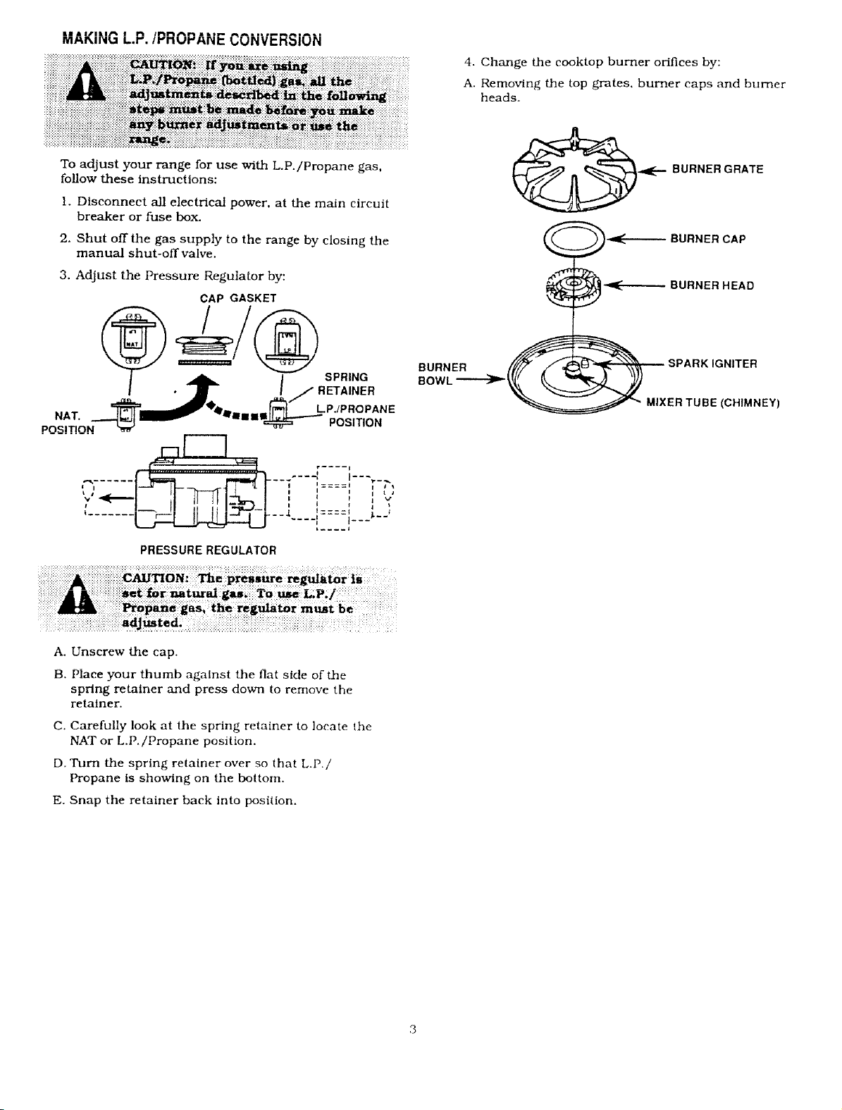
4. Change the cooktop burner orifices by:
A. Removing the top grates, burner caps and burner
heads.
To adjust your range for use with L.P./Propane gas,
follow these instructions:
I. Disconnect all electrical power, at the main circuit
breaker or fuse box.
2. Shut off the gas supply to the range by closing the
manual shut-off valve.
,HLUJLIbLLllt_ t_ressuz-e Kegulator oy:
CAP GASKET
===='
• _ I / RETAINER
.._ __'4'_1_ __ _ "_ LPJPROPANE
..._.....f __.---J....l__._.
' I Jl---_-m-|S-' I '::::' ' "
! I II ii i; i-_--I ! , ' , !
PRESSURE REGULATOR
I SPRING
POS,,,ON
BURNER GRATE
BURNER CAP
-ql_ BURNER HEAD
BURNER _:""_ SPARK IGNITER
_ MIXER TUBE (CHIMNEY)
A. Unscrew the cap.
B. Piaee your thumb against the flat side of the
spring retainer and press down to remove the
retainer.
C. Carefully look at the spring retainer to locate the
NAT or L.P./Propane position.
D. Turn the spring retainer over so that L.P./
Propane Is showing on the bottom.
E. Snap the retainer back into position.
Page 4
B. Remove the valve control knobs.
C. Through the openings, locate the valve bypass
screws located on the lower right side of the
valves.
....... e,_ ............... • ................. ,y, ,*=
clockwise rotation, the brass bypass screw.
J,,
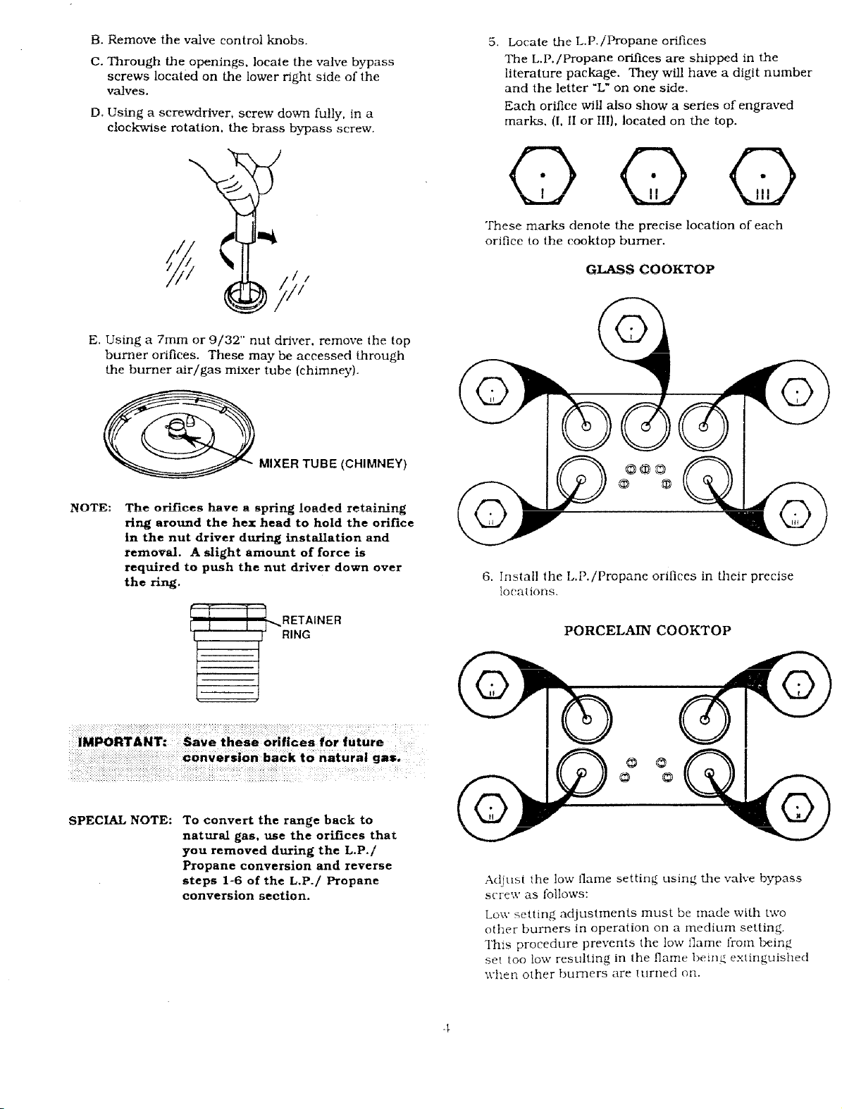
E. Using a 7rnm or 9/32" nut driver, remove the top
bumler orifices. These may be accessed through
the burner air/gas mixer tube (chimney).
5. Locate the L.P.iPropane orifices
The L.p./Propane orifices are shipped in the
literature package. They will have a digit number
and the letter "L" on one side.
Each orifice will also show a series of engraved
marks, (I. II or III). located on the top.
43(73
These marks denote the precise location of each
orifice to the cooktop burner.
G_S C00KTOP
_ MIXER TUBE (CHIMNEY)
NOT_: The otlflce_ have n _ntlna |nadr_ri rr_talnlna
.... _ _ - -"15 ............... e.o
SPECIAL NOTE:
ring around the hex head to hold the orifice
in the nut driver during installation and
removal. A slight amount of force is
required to push the nut driver down over
the ring.
To convert the range back to
naturaJ gas, use the orifices that
you removed during the L.P./
Propane conversion and reverse
steps 1-6 of the L.P./ Propane
conversion section.
6. Install the L.P./Propane orifices in their precise
IO1!;.t Llt)I l._i.
PORCELAIN COOKTOP
Adjust the low flame setting using the valve bypass
screw as follows:
Low setting adjustments must be made with two
other burners in operation on a medium setting.
i'his procedure prevents the low flame from being
set too low resulting in the flame t)ein_ extinguished
when other burners are turned on.
Page 5
IMPORTANT
Remove all packing material and literature from
cooktop before connecting gas and electrical supply
to range.
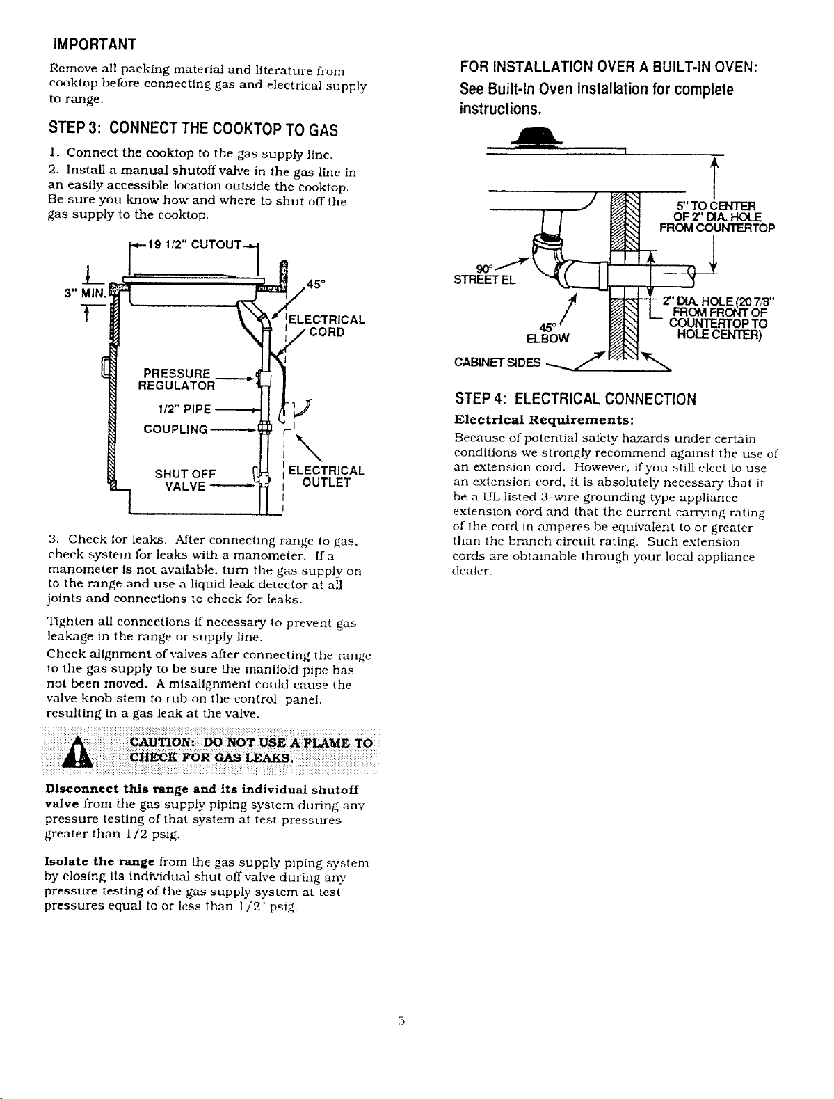
STEP3: CONNECT THE COOKTOPTO GAS
1. Connect the cooktop to the gas supply line.
2. Install a manual shutoffvalve in the gas line in
an easily accessible location outside the cooktop.
Be sure you know how and where to shut off the
gas supply to the cooktop.
FORINSTALLATIONOVER A BUILT-IN OVEN:
See Built-In Oven Installationfor complete
instructions.
I
T
if' TO CEh"IER
OF 2" DIA. HOLE
FROM COUN_TOP
45°
ELECTRICAL
£LECTRICAL
VALVE
3. Check for leaks. After connecting range to gas.
check system for leaks with a manometer. Ifa
manometer Is not available, turn the gas supply on
to the range and use a liquid leak detector at all
joints and connections to check for leaks,
Tighten all connections if necessary to prevent gas
leakage in the range or supply line.
Check alignment of valves after connecting the range
to the gas supply to be sure the manifold pipe has
not been moved. A misallgnment could cause the
valve knob stem to rub on the control panel.
resulting In a gas leak at the valve.
OUTLET
STREET EL
2" DIA. HOLE 120 7,'8"
FROM FRONT OF
COUNTERTOP TO
_IBOW
CABINET S_DES "-.-.-.._7
HOLECENTER)
STEP4: ELECTRICAL CONNECTION
Electrical Requirements:
Because of potential sal_ty hazards under certain
conditions we strongly recommend against the use of
an extension cord. However, if you still elect to use
an extension cord, it is absolutely necessary that it
be a UL listed 3-wire grounding type appliance
extension cord and that the current carrying rating
of the cord in amperes be equivalent to or greater
than the branch circuit rating. Such extension
cords are obtainable through your local appliance
dealer.
Disconnect this range and its individual shutoff
valve from the gas supply piping system during any
pressure testing of that system at test pressures
greater than 1/2 psig.
Isolate the range from the gas supply piping system
by closing Its individual shut off valve during any
pressure testing of the gas supply system at test
pressures equal to or less than 1/2" psig.
Page 6
GROUNDING
IMPORTANT: (Please read carefully)
FOR PERSONAL SAFETY, THIS APPLIANCE
MUST BE PROPERLY GROUNDED.
The power cord of this appliance is equipped with a
three-prong (grounding) plug which mates with a
standard three-prong grounding wall receptacle to
minimize the possibility of electric shock hazard from
this appliance.
The customer should have the wall receptacle and
circuit checked by a qualified electrician to make
sure the receptacle is properly grounded.
N and firm connection
L before use.
Insure proper ground
P
Where a standard two-prong wall receptacle is
encountered, it is the personal responsibility and
obligation of the customer to have it replaced with a
properly grounded three-prong wall receptacle.
DO NOT, UNDER ANY CIRCUMSTANCES,
CUT OR REMOVE THE THIRD (GROUND)
PRONG FROM THE POWER CORD.
USAGE SITUATIONS WHERE THE APPLIANCE
POWER CORD WILL BE DISCONNECTED
INFREQUENTLY.
For 15 amp circuit only, do not use an adaptor on a
20 amp circuit. Where local codes permit, a
TEMPORARY CONNECTION may be made to a
properly grounded two-prong wall receptacle by the
use of a UL listed adaptor available at most
hardware stores. The larger slot in the adaptor
must be aligned with the large slot in the wall
receptacle to provide proper polarity in the
connection of the power cord.
Insure proper ground
| and firm connection
beforeuse.
UNLESS THE SCREW IS METAL, AND NOT
INSULATED, AND THE WALL RECEPTACLE IS
GROUNDED THROUGH THE HOUSE WIRING. THE
CUSTOMER SHOULD HAVE THE CIRCUIT
CHECKED BY A QUALIFIED ELECTRICIAN TO
MAKE SURE THE RECEPTACLE IS PROPERLY
GROUNDED.
When disconnecting the power cord from the
adaptor, always hold the adaptor with one hand. If
this is not done the adaptor ground terminal is very
likely to break with repeated use. Should this
happen, DO NOT USE the appliance until a proper
ground has again been established.
USAGE SITUATIONS WHERE APPLIANCE POWER
CORD WILL BE DISCONNECTED FREQUENTLY.
Do not use an adaptor plug in these situations
because disconnection of the power cord places
undue strain on the adaptor and leads to eventual
failure of the adaptor ground terminal. The
customer should have the two-prong wall receptacle
replaced with a three-prong (grounding) receptacle
by a qualified electrician before using the appliance.
In Canada, mobile home installation must be in
accordance with the current CAN/CSA Z240/MH
Mobile Home Installation Code.
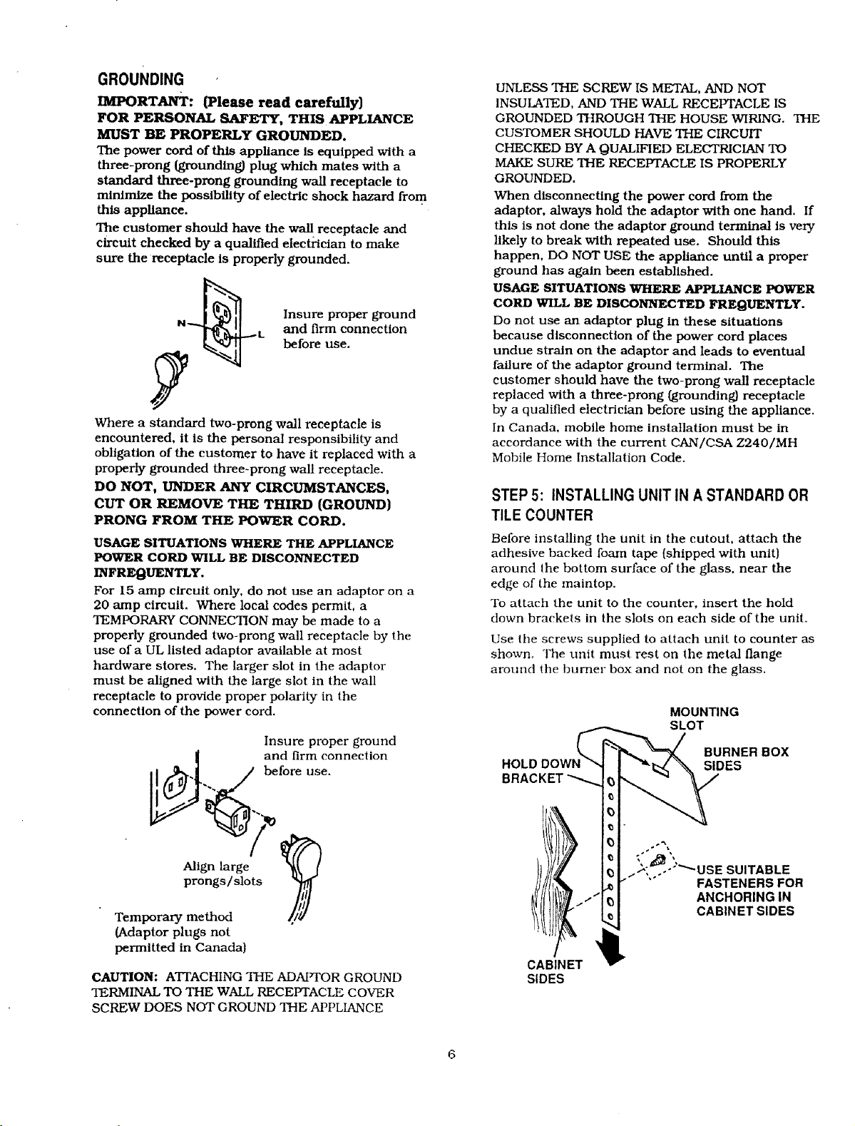
STEP5: INSTALLINGUNIT IN A STANDARDOR
TILE COUNTER
Before installing the unlt in the cutout, attach the
adhesive backed foam tape (shipped wlth unit)
around the bottom surface of the glass, near the
edge of the maintop.
To attach the unit to the counter, insert the hold
down brackets in the slots on each side of the unit.
Use the screws supplied to attach unit to counter as
shown, The unit must rest on the metal flange
around the burner box and not on the glass.
MOUNTING
SLOT
HOLDDOW!
B
BURNER BOX
SIDES
%
__-gn large
prongs/slots _
Temporary method ///1
(Adaptor plugs not
permitted in Canadal
CAUTION: ATTACHING THE ADAIq'OR GROUND
TERMINAL TO THE WALL RECEPTACLE COVER
SCREW DOES NOT GROUND THE APPLIANCE
...'1 _ ANCHORING IN
CABINET _
SIDES
{3 ..i "_ ."" USE SUITABLE
I_, CABINET SIDES
FASTENERS FOR
Page 7
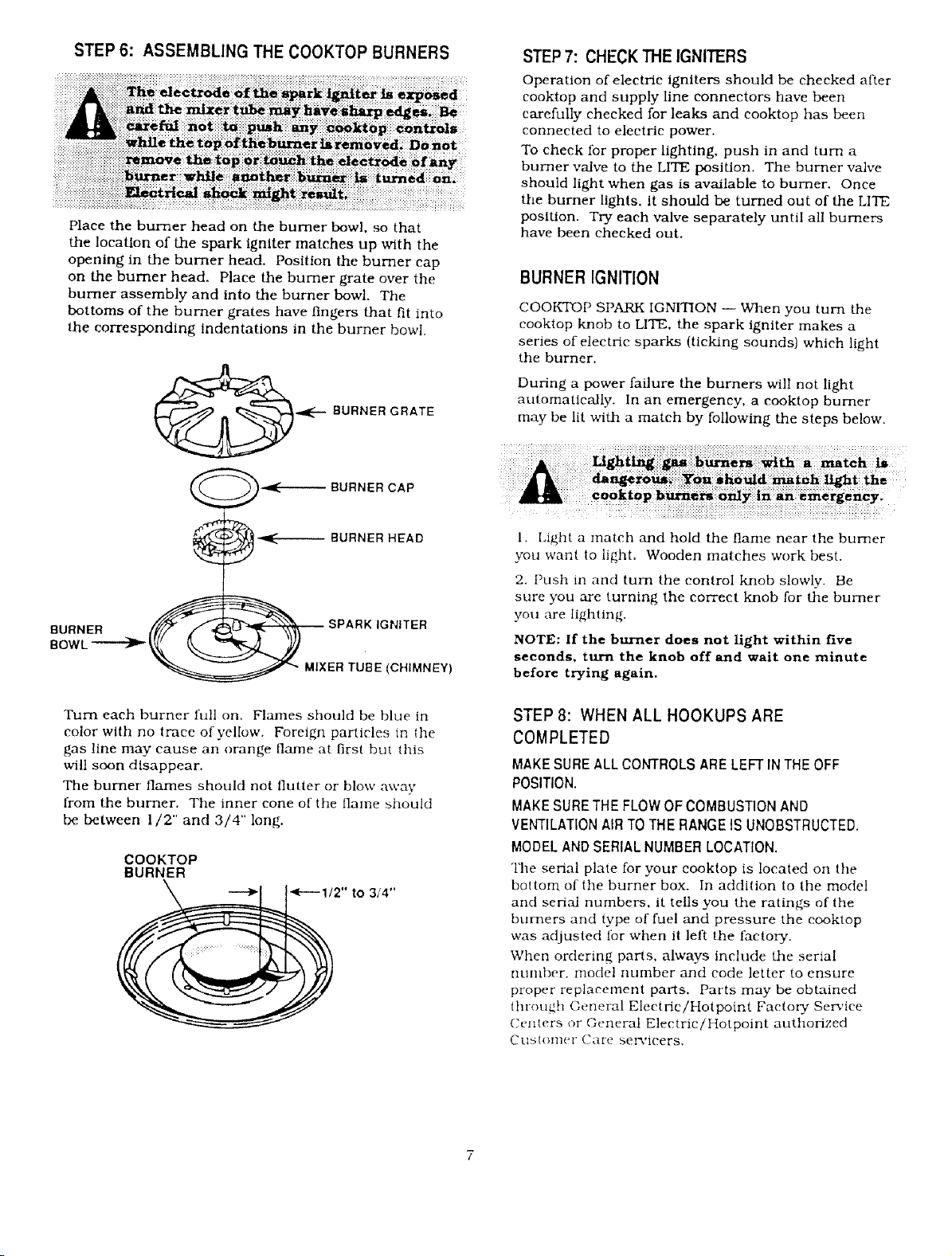
STEP 6: ASSEMBLING THE COOKTOP BURNERS
Place the burner head on the burner bowl. so that
the location of the spark igniter matches up with the
opening in the burner head. Position the burner cap
on the burner head. Place the burner grate over the
burner assembly and into the burner bowl. The
bottoms of the burner grates have fingers that fit into
the corresponding indentations in the burner bowl.
BURNER GRATE
STEP 7: CHECK THE IGNITERS
Operation of electric igniters should be checked after
cooktop and supply line connectors have been
carefully checked for leaks and cooktop has been
connected to electric power.
To check for proper lighting, push in and turn a
burner valve to the LITE position. The burner valve
should light when gas is available to burner. Once
the burner lights, it should be turned out of the LITE
position. Try each valve separately until all burners
have been checked out.
BURNERIGNITION
COOKTOP SPARK IGNITION -- When you turn the
cooktop Mmb to LITE. the spark igniter makes a
series of electric sparks {ticking sounds) which light
the burner,
During a power failure the burners will not light
automatically. In an emergency, a cooktop burner
may be lit with a match by following the steps below,
BURNER _ _ SPARK IGNITER
_ MIXER TUBE (CHIMNEY)
]'urn each burner full on. Flames should be blue in
color with no irace of yellow. Foreign particles in the
gas line may cause an orange flame at first but this
will soon disappear,
The burner" flames should not flutter or blow away
from the burner, Tile inner cone of the ilame should
be between 1/2" and 3/4" long.
COOKTOP
BURNER
1. Ligtlt a malch and hold the flame near the burner
you want to light. Wooden matches work best.
2. Push m and turn the control knob slowly. Be
sure you are turning the correct knob for the burner
you are lighting.
NOTE: If the burner does not light within five
seconds, turn the knob off and wait one minute
before trying again.
STEP8: WHENALL HOOKUPS ARE
COMPLETED
MAKE SURE ALL CONTROLS ARE LEFT IN THE OFF
POSITION.
MAKE SURE THE FLOW OF COMBUSTION AND
VENTILATION AIR TO THE RANGE IS UNOBSTRUCTED.
MODEL AND SERIAL NUMBER LOCATION.
The serial plale for your eooktop is located on the
bottom of tile burner box. In addition to the model
and serial numbers, it tells you the ratings of the
burners and type of fuel and pressure the cooktop
was adjusted for when it left the factory.
When ordering parts, always include the serial
nulnbcr, model number and code letter to ensure
proper replacement paris. Parts may be obtained
thl-ougil General Eleciric/Hotpoint Factory Sen'ice
Centers or General Electric/Hotpoint authorized
Cl.lSlOlllel* CaI-c servicers.
Page 8

NOTES
Pub. No. 31-10169
229c4053P039-1
R_d_ Paper
-- Printed in LaFaye_e, Georgia --
 Loading...