

Page 1
Use and Care & Installation Guide
Gas Downdraft Cooktop
GE Appliances
Safety Instructions................... 2–5
Operating Instructions, Tips
Controls ....................................................... 8, 9
Cookware ........................................................ 9
Electric Ignition .............................................. 8
Features ........................................................... 6
Surface Burner Modules ....... 6, 10–14, 17
Surface Burners ............................................. 6
Ventilation System ..................................... 15
Care and Cleaning................... 15–17
Control Knobs and Control Panel Seal..... 15
Grease Jar..................................................... 15
Griddle Accessory....................................... 17
Grill Burner.................................................... 16
Grill Cover ..................................................... 16
Grill Grates .................................................... 16
Igniters............................................................17
Porcelain Burner Basin.............................. 17
Porcelain Cooktop ...................................... 15
Surface Burners .......................................... 17
Ventilation System ..................................... 16
Problem Solver ............................. 30
More questions ?…call
GE Answer Center® 800.626.2000
Installation
Instructions ............................... 18–26
Converting to LP Gas....... 27-29
Consumer Services.................. 31
Appliance Registration................................. 2
Important Phone Numbers ...................... 31
Model and Serial Numbers ......................... 2
Warranty ....................................................... 32
811P409-60
164D3333P203
49-8976
Models: JGP18 JGP389
8-99 JR
Printed in USA
Page 2
2
HELP US HELPYOU…
Before using your cooktop, read this
guide carefully.
It is intended to help you operate and maintain your
new cooktop properly.
Keep it handy for answers to your questions.
If you don’t understand something or need more help, call:
GE Answer Center
®
800.626.2000
24 hours a day, 7 days a week
Write down the model and serial numbers.
You’ll find them on a label located on the side of the
plenum under the cooktop. These numbers are also on
the Consumer Product Ownership Registration Card
that came with your cooktop. Before sending in this
card, please write these numbers here:
Model Number Serial Number
Use these numbers in any correspondence or service
calls concerning your cooktop.
If you received a damaged cooktop…
Immediately contact the dealer (or builder) that sold
you the cooktop.
Save time and money.
Before you request service…
Check the Problem Solver in the back of this guide.
It lists causes of minor operating problems that you
can correct yourself.
— Do not store or use gasoline or other
flammable vapors and liquids in the
vicinity of this or any other appliance.
— WHAT TO DO IF YOU SMELLGAS
•Do not try to light any appliance.
•Do not touch any electrical switch; do
not use any phone in your building.
•Extinguish any open flame.
•Immediately call your gas supplier from
a neighbor’s phone. Follow the gas
supplier’s instructions.
•If you cannot reach your gas supplier,
call the fire department.
— Installation and service must be
performed by a qualified installer,
service agency or the gas supplier.
WARNING: If the information in this
guide is not followed exactly, a fire or
explosion may result causing property
damage, personal injury or death.
IFYOU NEED SERVICE…
To obtain service, see the Consumer Services page
in the back of this guide.
We’re proud of our service and want you to be
pleased. If for some reason you are not happy with
the service you receive, here are some steps to follow
for further help.
FIRST, contact the people who serviced your
appliance. Explain why you are not pleased.
In most cases, this will solve the problem.
NEXT, if you are still not pleased, write all the
details—including your phone number—to:
Manager, Consumer Relations
GE Appliances
Appliance Park
Louisville, KY 40225
Page 3
3
Important Safety Instructions
IMPORTANT SAFETYINSTRUCTIONS
Read all instructions before using this appliance.
IMPORTANT SAFETY NOTICE
• The California Safe Drinking Water and Toxic
Enforcement Act requires the Governor of
California to publish a list of substances known to
the state to cause cancer, birth defects or other
reproductive harm and requires businesses to warn
customers of potential exposure to such substances.
• Gas appliances can cause minor exposure to
four of these substances, namely benzene, carbon
monoxide, formaldehyde and soot, caused primarily
by the incomplete combustion of natural gas or
LP fuels. Properly adjusted burners, indicated by
a bluish rather than a yellow flame, will minimize
incomplete combustion. Exposure to these substances
can be minimized further by venting with an open
window or using the ventilation fan.
All appliances—regardless of the manufacturer—
have the potential through improper or careless
use to create safety problems. Therefore the
following safety precautions should be observed.
When You Get Your Cooktop
When you get your cooktop, have the installer
show you the location of the gas cut-off valve
and how to shut it off if necessary.
• Have your cooktop installed and properly
grounded by a qualified installer, in accordance
with the Installation Instructions. Any adjustment
and service should be performed only by qualified
gas cooktop installers or service technicians.
• Plug your cooktop into a 120-volt grounded
outlet only. Do not remove the round grounding
prong from the plug. If in doubt about the
grounding of the home electrical system, it is your
personal responsibility and obligation to have an
ungrounded outlet replaced with a properlygrounded three-prong outlet in accordance with
the National Electrical Code. Do not use an
extension cord with this appliance.
• Be sure all packing materials are removed from
the cooktop before operating it, to prevent fire or
smoke damage should the packing material ignite.
• Be sure your cooktop is correctly adjusted by a
qualified service technician or installer for the
type of gas (natural or LP) which is to be used.
Your cooktop can be converted for use with either
type of gas. See the Installation Instructions. Your
model is factory adjusted for use with natural gas.
• Do not attempt to repair or replace any
part of your cooktop unless it is specifically
recommended in this guide. All other servicing
should be referred to a qualified technician.
WARNING—TO REDUCE THE RISK OF
FIRE, ELECTRIC SHOCK, OR INJURYTO
PERSONS, OBSERVE THE FOLLOWING:
A. Use this unit only in the manner intended
by the manufacturer. If you have questions,
contact the manufacturer.
B. Before Servicing or Cleaning the Unit, Switch
Power Off At Service Panel.
C. When cutting or drilling into wall or ceiling
do not damage electrical wiring and other
hidden utilities.
D.
Ducted fans must always be vented to the outdoors.
E.
To reduce the risk of fire, use only metal ductwork.
WARNING—TO REDUCE THE RISK
OFA COOKTOPGREASE FIRE:
A. Keep fan, filters and grease laden surfaces clean.
B. Always turn vent ON when cooking at high heat.
C.
Use high settings on cooktop only when necessary.
Heat oil slowly on low to medium setting.
D.
Never leave the cooktop unattended when cooking.
E. Always use cookware and utensils appropriate
for the type and amount of food being prepared.
CAUTION—For General Ventilating Use Only.
Do Not Use To Exhaust Hazardous Or Explosive
Materials and Vapors.
(continued next page)
Page 4
44
IMPOR TANT SAFETY INSTRUCTIONS
(continued)
Using Your Cooktop
• Do not leave children alone or unattended
where a cooktop is hot or in operation.
They could be seriously burned.
•
CAUTION: Items of interest to children should
not be stored in cabinets above a cooktop—
children climbing on the cooktop to reach items
could be seriously injured.
• Clean the cooktop with caution. If a wet sponge
or cloth is used to wipe spills on a hot cooktop,
be careful to avoid steam burns.
• Do not clean the cooktop with flammable or
volatile cleaning fluids.
• Do not clean the cooktop when the appliance
is in use.
• Let the burner grates and other surfaces cool
before touching them or leaving them where
children can reach them.
• Never wear loose-fitting or hanging garments
while using the appliance. Be careful when
reaching for items stored in cabinets over the
cooktop. Flammable material could be ignited
if brought in contact with flame or hot surfaces
and may cause severe burns.
• For your safety, never use your appliance for
warming or heating the room. Prolonged use
of the cooktop in this way can be hazardous.
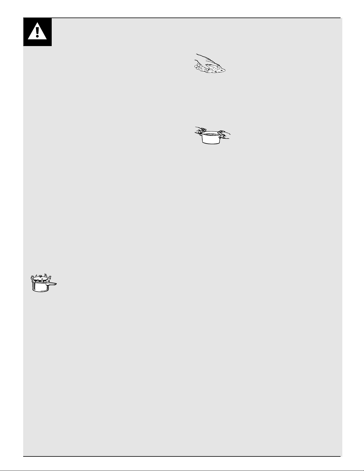
• Do not use water on grease fires.
Never pick up a flaming pan.
Turn the controls off. Smother a
flaming pan on a surface burner by covering
the pan completely with a well-fitting lid,
cookie sheet or flat tray. Use a multi-purpose
dry chemical or foam-type fire extinguisher.
Flaming grease outside a pan can be put out
by covering it with baking soda or, if available,
by using a multi-purpose dry chemical or foamtype fire extinguisher.
• Do not store flammable materials near the
cooktop. Do not store or use gasoline or other
flammable vapors and liquids in the vicinity of
this or any other appliance.
• Do not let cooking grease or other
flammable materials accumulate
in or near the cooktop.
• Never leave surface burners unattended at
high flame settings. Boilovers cause smoking
and greasy spillovers that may catch on fire.
• Adjust surface burner flame size so it does
not extend beyond the edge of the cookware.
Excessive flame is hazardous.
• Use only dry pot holders—
moist or damp pot holders on hot
surfaces may result in burns from
steam. Do not let pot holders come near open
flames when lifting cookware. Do not use a towel
or other bulky cloth in place of a pot holder.
• To minimize the possibility of burns, ignition
of flammable materials and spillage, turn
cookware handles toward the side or center of
the cooktop without extending over adjacent
burner or vent area.
• Always turn the surface burners to off before
removing the cookware.
• Carefully watch foods being fried at high
flame setting.
• Foods for frying should be as dry as possible.
Frost on frozen foods or moisture on fresh foods
can cause hot fat to bubble up and over the sides
of the pan.
• Use least possible amount of fat for effective
shallow or deep-fat frying. Filling the pan too
full of fat can cause spillovers when food is
added.
• If a combination of oils or fats will be used
in frying, stir together before heating, or as fats
melt slowly.
• Always heat fat slowly, and watch as it heats.
• Use a deep fat thermometer whenever
possible to prevent overheating fat beyond
the smoking point.
Page 5
5
Important Safety Instructions
• Use proper pan size—Avoid pans that are
unstable or easily tipped. Select cookware having
flat bottoms large enough to properly contain food
and avoid boilovers and spillovers, and large
enough to cover burner grate. This will both save
cleaning time and prevent hazardous accumulations
of food, since heavy spattering or spillovers left on
cooktop can ignite. Use pans with handles that can
be easily grasped and remain cool.
• To avoid the possibility of a burn, always be
certain that the controls for all burners are at
the off position and all grates are cool before
attempting to remove a grate.
• If the cooktop is located near a window, do not
use long curtains which could blow over the burners
and create a fire hazard.
• If you smell gas, turn off the gas to the cooktop
and call a qualified service technician. Never use
an open flame to locate a leak.
• Do not cover or block the area around the
cooktop knobs. This area must be kept clear for
proper ventilation and burner performance.
• Cook meat and poultry thoroughly—meat to
at least an INTERNAL temperature of 160° F.
and poultry to at least an INTERNAL temperature
of 180° F. Cooking to these temperatures usually
protects against foodborne illness.
• When using glass cookware make sure it is
designed for cooktop cooking.
• Always use the LITE position when igniting
burners and make sure the burners have
ignited.
• Do not touch grill and surface burner areas,
or perimeter trim around cooktop. During and
after use, these areas may be hot enough to cause
burns. Avoid contact with these areas by clothing
or other flammable materials until they have had
sufficient time to cool.
• Do not use cookware on the grill section of
this cooktop.
• Do not heat unopened food containers. Buildup
of pressure may cause the container to burst and
result in injury.
• Keep all controls “OFF” when the cooktop is
not in use.
• Always allow hot pans to cool in a safe place
out of the reach of small children.
• This cooktop has been tested for safe
performance using conventional cookware.
Do not use any devices or accessories that are
not specifically recommended in this guide.
Do not use stovetop grills or burner covers for the
surface burners. The use of devices or accessories
that are not specifically recommended in this
guide can create serious safety hazards, result
in performance problems and reduce the life
of the components.
• Do not use aluminum foil to line aeration tray
or burner basin. Restriction of normal air flow
may result in unsafe operation.
• Keep plastic away from all burners.
• Do not use a wok on the cooking surface if the
wok has a round metal ring which is placed
over the burner grate to support the wok.
This ring acts as a heat trap which may damage
the burner grate and burner head. Also, it may
cause the burner to work improperly. This may
cause a carbon monoxide level above that allowed
by current standards, resulting in a health hazard.
SAVE THESE
INSTRUCTIONS
Page 6
6
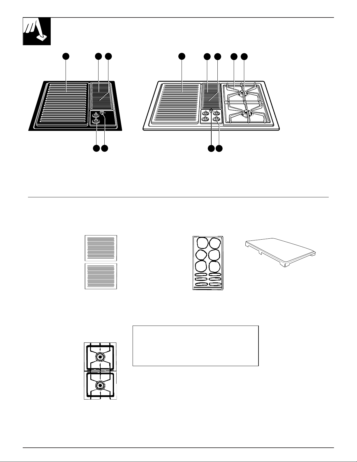
FEATURES OFYOUR COOKTOP
JGP18 JGP389
1 2 3 1
2 4 5
7 6
1. Grill Module
(optional on JGP389)
2. Vent (fan operates automatically
when grill is in use)
3. Vent Filters (below the vent grille)
4. Burner Grates
5. Surface Burners
6. Surface Burner Controls
7. Vent Control
3
Accessories
Grill
Model JXGG89
Consists of two
black grill grates
and a grill burner.
Surface Burner Module
Model JXGB89
Includes surface
burner assembly,
aeration tray, and
two surface burner
grates.
Griddle
Model JXGL89
Can be used only
with the grill module.
Self-draining griddle
makes many favorite
foods easier to fix.
Family-sized surface
lets you cook several
pancakes, hamburgers,
or grilled sandwiches
at the same time.
Grill Cover
Model JXGC89
Attractive grill cover protects the
grill when not in use. Textured
steel with molded handles.
6 7
NOTE: Optional surface burner module
(JXGB89) can replace the grill burner.
Burners supplied with cooktop (JGP389) and
optional module air shutters have been
adjusted for compatibility on both sides.
Page 7

7
NOTES
Page 8
SURFACE BURNERS
(on some models)
Electric Ignition
Your surface burners are lit by electric ignition, eliminating the need for
standing pilots with constantly burning flames.
In case of a power outage, you can light the surface burners on your
cooktop with a match. Hold a lit match to the burner, then turn the control
knob to the high position. Use extreme caution when lighting the
burners this way.
Surface burners in use when an electrical power failure occurs will
continue to operate normally.
IN CASE OF APOWER FAILURE DO NOT USE THE GRILL.
THE VENTILATION SYSTEM WILL NOT OPERATE.
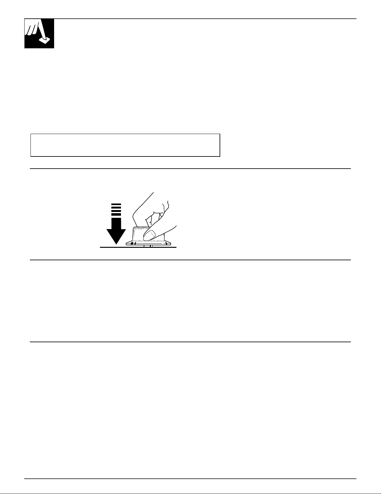
To Light a Burner
Push the control knob in
and turn it to LITE. You
will hear a little clicking
noise—the sound of the
electric ignition spark
that lights the burner.
After the burner ignites, turn the knob to adjust the
flame size.
To turn a burner off, turn the knob clockwise, as far
as it will go, to the OFF position.
• Do not operate the burner for an extended period of
time without cookware on the grate. The finish on the
grate may chip without cookware to absorb the heat.
• Check to be sure the burner you turn on is the one
you want to use.
• Be sure the burners and grates are cool before you
place your hand, a pot holder, cleaning cloths or
other materials on them.
• When using the surface burners, if you find that the
LO setting is too hot for delicate foods, you can
adjust the knob below the LO setting.
• Only surface burners may be used on the right side.
• Do not allow large pans to extend over the
control knobs. Heat trapped between large pans
and control knobs could cause possible damage
to the control knobs.
Cooking Guide for Using Heat Settings
HI—Quick start for cooking; brings water to a boil.
Medium high—(Setting halfway between the
midpoint and HI) Fast fry, pan broil; maintains a fast
boil on large amounts of food.
Medium—(Midpoint setting approximately halfway
between HI and LO) Sauté and brown; maintains a
slow boil on large amounts of food.
Medium low—(Setting halfway between midpoint
and LO) Cook after starting at HI; cooks with little
water in covered pan.
LO—Steam rice, cereal; maintains serving temperature
of most foods. Slow cooking and simmering.
NOTE:
• At HI and medium high settings, never leave food
unattended. Boilovers cause smoking; greasy
spillovers may catch fire.
• At medium low to LO settings, melt chocolate
and butter.
8
Page 9
Surface Burners
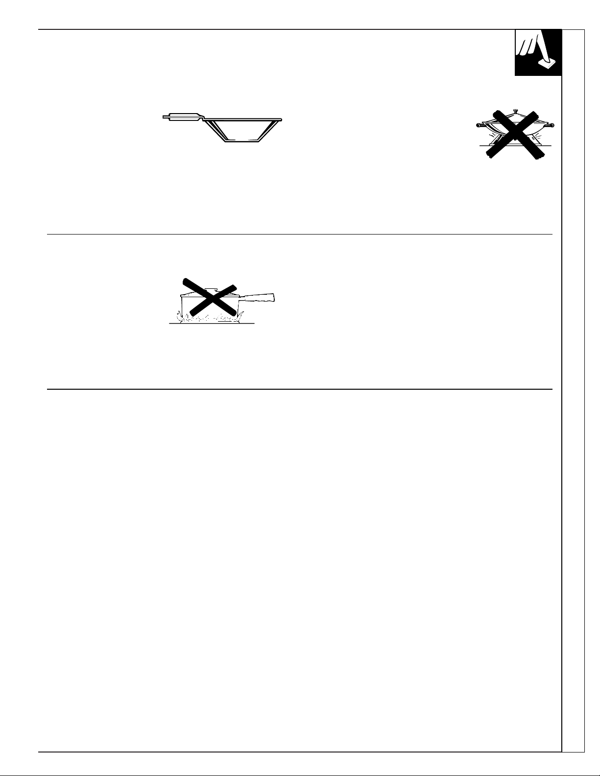
Wok Cooking
We recommend that you
use only a flat-bottomed
wok. They are available
at your local retail store.
Do not use woks that have
support rings. Use of these types
of woks, with or without the ring
in place, can be dangerous.
Placing the ring over the burner
grate may cause the burner to work improperly
resulting in carbon monoxide levels above allowable
current standards. This could be dangerous to your
health. Do not try to use such woks without the ring.
You could be seriously burned if the wok tipped over.
How to Select Flame Size
Watch the flame, not the
knob, as you reduce heat.
The flame size on a gas
burner should match the
cookware you are using.
FOR SAFE HANDLING OF COOKWARE, NEVER
LET THE FLAME EXTEND UP THE SIDES OF
THE COOKWARE. Any flame larger than the bottom
of the cookware is wasted heat and only serves to
heat the handle.
IMPORTANT: Leave a minimum of 1
1
⁄
2
"
between
the side of the pan and surrounding surfaces, such as
countertop backsplash or side walls, to allow heat to
escape to avoid possible damage to these areas.
9
Cookware
Aluminum: Medium-weight cookware is
recommended because it heats quickly and evenly.
Most foods brown evenly in an aluminum skillet.
Use saucepans with tight-fitting lids for cooking
with minimum amounts of water.
Cast Iron: If heated slowly, most skillets will
give satisfactory results.
Enamelware: Under some conditions, the
enamel of some cookware may melt. Follow
cookware manufacturer’s recommendations for
cooking methods.
Glass: There are two types of glass cookware—
those for oven use only and those for surface
cooking (saucepans, coffee and teapots). Glass
conducts heat very slowly.
Heatproof Glass Ceramic: Can be used for
either surface or oven cooking. It conducts heat
very slowly and cools very slowly. Check cookware
manufacturer’s directions to be sure it can be used
on gas cooktops.
Stainless Steel: This metal alone has poor heating
properties, and is usually combined with copper,
aluminum or other metals for improved heat
distribution. Combination metal skillets generally
work satisfactorily if they are used at medium heat
as the manufacturer recommends.
Page 10
10
SURFACE BURNER MODULE
To Install Burner Module To Remove Burner Module
1. Be sure all control knobs are turned off.
2. If the grill burner grates are in place, remove them
before installing a surface burner module. Clean
burner basin of any grease accumulation. See the
Care and Cleaning section.
3. Position the burner assembly with the mixer tube
openings toward the orifices. Slide the burner
assembly toward the orifices until the opening
for the igniter is over the igniter. Lower into place
until the side openings are resting on the burner
supports and the igniter is centered between the
two flash tubes.
4. Install the aeration tray by inserting the prong at the
end of the pan into the opening in the end of the
burner basin. Lower the opposite end into the cooktop.
1. The control knobs should be in the OFF position and
the cooktop should be cool.
2. Remove the aeration tray by lifting up the front end
on the right side (back end on the left side) until the
top clears the opening of the cooktop by about 5 inches.
3. Hold aeration tray by the sides and slide away to
remove the prong from the opening and clear the
surface burners.
4. Lift up on the sides of the surface burner assembly
bracket about 2 inches. Slide away from the orifices.
NOTE: If you have cooktop JGP389, you can
purchase another 2-burner module, model JXGB89.
This module is specially adjusted for use on the left
side only. You may notice that food cooks a bit more
slowly on this module. This is because the heat output
has been reduced for best grill cooking performance.
NOTE: Optional surface burner module
(JXGB89) can replace the grill burner. Burners
supplied with cooktop (JGP389) and optional
module air shutters have been adjusted for
compatibility on both sides.
Page 11

11
GRILL MODULE
The grill consists of two black grill grates and a grill burner. Only install
the grill on the left side of your cooktop.
To Install Grill Module
1. Before installing grill components, be certain
control knobs are in the OFF position.
2. Position the grill burner with mixer tube openings
toward the orifices. Slide the burner towards the
orifices until the igniter is in between front and rear
grill sections. Lower into place until side openings
are resting on the burner support pins.
3. Place the grill grates on the top of the cooktop.
Surface Burner Module Grill Module
To Remove Grill Module
1. Remove grill components once they are cool.
Be sure control knobs are in the OFF position.
2. Remove grill grates.
3. Remove grill burners.
NOTE: Before using the grill for the first time, heat
the grill burner to remove the protective shipping
coating. Heat the grill on HI for 10 minutes and use
the vent system to remove any additional smoke
during cooling.
Page 12

GRILLING
Using the Grill
• The vent fan will operate automatically when the
grill burner is in use.
• Before using the grill for the first time, wash grill
grates in hot soapy water. Rinse and dry.
• Precondition grates by brushing with vegetable oil
or spraying with a nonstick coating such as Pam
®
.
Do this every time before you grill.
• For easier clean-up, spray grates and burner basin
with a nonstick coating.
• Use nonmetallic spatulas or utensils to prevent
damaging the nonstick grill grate finish.
• Preheat the grill on high for 5 to 10 minutes.
Preheating improves the flavor and appearance
of meats and quickly sears the meat to help retain
the juices.
• Excessive amounts of fat should be trimmed
from meats. Some fat is necessary to produce the
smoke needed for that smoked “outdoor” flavor.
However, excessive fat can create cleaning and
flare-up problems.
• Allowing excessive amounts of grease or drippings
to constantly flame voids the warranty on the grill
grates. Excessive flare-ups indicate that either the
grill interior needs to be cleaned, excessive amounts
of fat are in the meat or that the meat was not
properly trimmed.
• Grease drippings will occasionally ignite to produce
harmless puffs of flame for a second or two. This is
a normal part of the cooking process.
• Never leave the grill unattended during operation.
IMPORTANT:
• Do not use aluminum foil inside the grill area.
• Do not use charcoal or wood chips in the
grill area.
• Do not allow burner basin to become
overloaded with grease. Clean after each use.
• Do not cover grates completely with meat.
Leave air space between each steak, etc. to allow
proper ventilation as well as to prevent flare-ups.
Should a Sustained Flare-Up Occur
1. Use the vent control to turn the fan on.
2. Immediately turn the grill control knobs to the OFF position.
3. Remove the meat from the grill.
Grilling Tips
With your grill, any food you’ve considered “at its
best” when prepared outdoors can now be prepared
indoors with less fuss and great flavor.
The following suggestions are good rules to follow
and will increase your enjoyment of the equipment. Be
sure to follow directions in this guide for using the grill.
Suggested cooking times and control settings are
approximate due to variations in meats. Experience
will quickly indicate cooking times as well as which
settings work best.
For best results, buy top grade meat. Meat that is at
least 3/4 inch will grill better than thinner cuts.
For the attractive “branded” look on steaks, be sure the
grill is preheated. Allow one side of the meat to cook to
the desired doneness, or until the juices appear on the
top surface, before turning. Turn steaks and hamburgers
just once. Moving the food around causes loss of juices.
When basting meats or applying sauces to foods,
remember that excessive amounts wind up inside your
grill and do not improve the food flavor. Apply sauces
during the last 15 to 20 minutes of cooking time unless
the recipe specifies otherwise. Sugar-based marinade,
(for example, barbecue sauce) will caramelize on grill
grates and will create a cleaning chore.
There are many meat marinades which will help tenderize
less expensive cuts of meat for cooking on the grill.
Certain foods, such as poultry and non-oily fish, may
need some extra fat. Brush with oil or melted butter
occasionally while grilling.
Use tongs with long handles or spatulas for turning
meats. Do not use forks as these pierce the meat,
allowing juices to be lost.
To help retain meat juices, salt after turning meat or
after cooking is completed.
Score the fat on the edges of steaks but do not cut into
the meat to prevent curling while cooking.
12
Page 13

13
GRILLING GUIDE
Preheat the grill on high for 5 to 10 minutes for best flavor.
Type Control Setting Cooking Time Procedure
Meat
Steak (1/2–3/4")
Rare HI 6 to 10 minutes Turn after 3 to 5 minutes.†
Medium HI 10 to 16 minutes Turn after 5 to 8 minutes.
Well HI 21 to 24 minutes Turn after 6 to 12 minutes.
Steak (1–1/4")
Rare HI 14 to 24 minutes Turn after 7 to 12 minutes.†
Medium HI 18 to 30 minutes Turn after 9 to 15 minutes.
Well HI 24 to 34 minutes Turn after 12 to 17 minutes.
Hamburgers (3–4 oz.) Medium 20 to 25 minutes Turn after half the time.
Pork chops Medium 20 to 30 minutes Turn occasionally.
Fully cooked smoked pork chops Medium 10 to 15 minutes Turn after half the time.
Ham slices Medium 15 to 20 minutes Turn after half the time.
Pork ribs Medium 50 to 65 minutes Turn occasionally. Brush
with barbecue sauce during
the last 15 minutes.
Fully cooked sausages
Hot dogs, brats HI 7 to 12 minutes Turn occasionally.
Polish HI 13 to 16 minutes Turn occasionally.
Fresh sausages
Links Medium 15 to 25 minutes Turn occasionally.
Patties ( 3" diameter) Medium 15 to 20 minutes Turn after half the time.
Italian sausage Medium 25 to 30 minutes Pierce casing with a fork.
Turn once.
Lamb chops Medium 20 to 30 minutes
Turn occasionally. Brush with
glaze, if desired.
Poultry
Chicken
Pieces: bone-in Medium 35 to 50 minutes Turn occasionally.
Boneless breasts Medium 25 to 35 minutes Turn occasionally.
Wings Medium 25 to 35 minutes Turn occasionally.
Cornish hen (halved) Medium 35 to 45 minutes Turn occasionally.
Fish
Small, whole (1") Medium 15 to 20 minutes Brush with butter. Turn after
half the time.
Steaks (1") Medium 20 to 25 minutes Brush with butter. Turn after
half the time.
Fillets—with skin on (1/2") Medium 10 to 15 minutes Start skin side down. Brush
with butter. Turn after half
the time.
Shrimp (skewered) Medium 10 to 20 minutes Turn and brush with butter
or marinade frequently.
Bread
Garlic bread Medium 4 to 6 minutes Turn after half the time.
Hot dog or hamburger buns Medium 1 to 2 minutes Turn after half the time.
†The U. S. Department of Agriculture says
“Rare beef is popular, but you should know that cooking it to only 140°F. means some
food poisoning organisms may survive.” (Source: Safe Food Book. Your Kitchen Guide. USDA Rev. June 1985.)
Grilling Grilling Guide
Page 14

14
GRILL COVER
The texture steel grill cover makes an attractive cover for the grill section
of the cooktop when it is not in use.
To Use the Grill Cover
Remove the cover before heating the grill. Since a
heated grill cover would not appear hot, this could
cause accidental burns should it be touched. Heating
the grill cover could also damage the finish.
Do not place the grill cover over a heated grill. Let
the grill cool before putting the cover in place.
Use the cover over the grill grates only. Do not place
the cover over the griddle or surface burner grates.
IMPORTANT:Although the finish is very durable,
care should be taken to avoid setting utensils or other
items on the surface that could cause scratches.
DO NOT set extremely hot containers on the
surface, including handles, since these could mar or
discolor the cover. It is an attractive cover and proper
care will keep it that way.
GRIDDLE ACCESSOR Y
Using the Griddle
1. Before the first use, wash your new griddle in hot
soapy water, rinse and dry. Then “condition” the
surface by wiping on a thin coating of cooking oil
or shortening. Remove excess oil or shortening by
wiping again with another paper towel.
2. Insert grill burner. DO NOT use grill grates.
3. Place griddle over grill burner so that the drain
holes are in front. This will permit excess grease
to be collected in the grease container.
4. Preheat the griddle 5 to 10 minutes at the specified
setting as noted in the Griddle Guide.
5. Use non-metallic spatulas or utensils while
cooking to prevent damaging the finish.
Control Approximate Cooking Approximate Cooking
Food Item Setting Time First Side Time Second Side
Bacon Medium 4-5 minutes 3-4 minutes
Buns HI 2-3 minutes
Eggs Medium 2-3 minutes 1 minute
Fish sticks (frozen) Medium 7-8 minutes 5-7 minutes
Ham slice Medium 6-7 minutes 5-6 minutes
Hamburgers Medium 5-7 minutes 4-6 minutes
Hot dogs HI 5 minutes 5 minutes
French toast HI 2-4 minutes 2-3 minutes
Grilled cheese sandwiches HI 2-3 minutes 2-3 minutes
Pancakes HI 1-2 minutes 1-2 minutes
Sausage patties Medium 6-8 minutes 4-5 minutes
GRIDDLE GUIDE
NOTE: These are suggested guides for control settings and times. Factors
such as low gas pressure may affect the times and control settings which
provide the best results. Preheat 5 to 10 minutes at specified setting.
Page 15

VENTILATION SYSTEM
The built-in vent system helps remove cooking vapors, odors and
smoke from foods prepared on the cooktop, grill and griddle
accessories. Continuous use of the vent system helps keep the kitchen
comfortable and less humid, reducing cooking odors and moisture that
normally creates a frequent need for cleaning.
Using the Ventilation System
To turn the fan on, use the on/off control located on the control panel.
The fan will operate automatically when the grill burner is in use.
CARE AND CLEANING
Before cleaning any part of your cooktop, be sure all controls are off and
DISCONNECT ELECTRICAL POWER TO THE COOKTOP at the
fuse box or circuit breaker panel, or pull the cooktop power plug, located
beneath the cooktop and inside the cabinets.
Do not operate the cooktop without all parts in place.
Control Knobs and Control Panel Seal Grease Jar
After grilling there may be soot on the knobs and
control panel seal. This soot can be removed by
scrubbing with a plastic scrubber and mild
dishwashing detergent. The control knobs may
be removed for cleaning.
To remove a knob, pull it straight up.
Wash the knobs in soap and water but do not soak.
Avoid getting water down into the knob stem holes.
Wipe with a sponge, damp cloth or paper towel. Do
not scrub with steel wool pads or abrasive cleansers.
To replace a knob, match the flat part of the knob
opening with the flat side of the shaft.
A grease jar is located
below the grill basin pan
under the countertop.
Check periodically to
prevent spillovers.
Unscrew and remove.
If the jar is broken,
replace with any heat
tempered jar, such as
a canning jar, which has
a standard screw neck.
Porcelain Cooktop
The porcelain enamel finish is sturdy but breakable if
misused. This finish is acid-resistant. However, any
acidic foods spilled (such as fruit juices, tomato or
vinegar) should not be permitted to remain on the
finish.
If acids spill on the cooktop while it is hot, use a
dry paper towel to wipe it up right away. When the
surface has cooled, wash with soap and water or
cleansing powders. Rinse well.
For other spills, such as fat spatterings, wash with
soap and water or cleansing powders after the surface
has cooled. Rinse well. Polish with a dry cloth.
(continued next page)
Grill Cover Griddle Accessory Griddle Guide Ventilation System Care and Cleaning
15
Page 16

16
CARE AND CLEANING
(continued)
Grill Burner Grill Grates
The grill burner should
be cleaned after each
use. It can be cleaned
with soapy steel wool
pad or in the dishwasher.
Rinse and dry thoroughly
before using again. For
heavy soil, the burner
should be cleaned first
with a soapy steel wool pad, rinsed and dried. Then it
can be cleaned in a self-cleaning oven for two hours.
NOTE: Check to be sure all burner ports are open.
To open clogged ports, insert a twist tie directly into
each port.
The grates should be cleaned
after each use. They can be
cleaned with detergent and a
plastic scrubber, such as Tuffy,
or washed in the dishwasher if
burned on residue is first
removed. For heavy soil, grates can be soaked in hot,
soapy water mixed with household ammonia.
Do not use metal brushes or abrasive scouring
pads or other scrubbers intended to clean outdoor
grills. These will remove the finish as well as
scratch the grates. Do not clean in a self-cleaning
oven or use oven cleaners on the grates.
Grill Cover
The grill cover may be easily cleaned with a damp cloth and mild detergent
or liquid household cleanser. Rinse and dry thoroughly.
DO NOT clean in a dishwasher.
Ventilation System
Vent Grille: The vent
grille lifts off easily.
Wipe clean or wash
in the sink with mild
household detergents.
Filter: Turn off the fan
before removing. Turn
the filter retainer clip
to remove the filter.
The filter is a permanent
type and should be
cleaned when soiled.
Clean in the sink with
warm water and liquid
dishwashing detergent.
IMPORTANT: Do not operate the fan without the
filter. The filter should always be placed at an angle.
As you face the front of the cooktop, the top of the
filter should rest against the left side of the vent
opening and the bottom of the filter should rest
against the right side of the ventilation chamber at
the bottom. If the filter is flat against the fan wall,
ventilation effectiveness is reduced.
Ventilation Chamber: This area, which houses the
filter, should be cleaned in the event of spills or
whenever it becomes coated with a film of grease.
The ventilation chamber may be cleaned with a paper
towel, damp cloth or sponge and a mild household
detergent or cleanser.
Page 17

17
Care and Cleaning
Igniters Griddle Accessory
It is important to keep igniter port openings on
burners clear and free of obstructions to avoid ignition
failure and possible gas buildup. If the port openings
are blocked, use a twist tie to remove food particles.
The igniter cap and stem can be cleaned with warm
soapy water and a plastic scrubber. The wire electrode
inside the cap can be cleaned with a small brush.
Rinse and dry.
DO NOT immerse a hot griddle in cold water.
Once the griddle has cooled, wash with soap or
detergent in hot water in the sink. Be sure to remove
all food residue before cooking on the griddle again.
Remove stubborn spots with a plastic scouring pad. For
best results, use only those cleaning products which
are recommended for use when cleaning non-stick
surfaces. Do not use steel wool or coarse scouring pads.
DO NOT wash in a dishwasher.
Porcelain Burner Basin
This area is located under the grill and surface burners and should be
cleaned after each use of the grill.
To remove light soil, clean with soapy water or with a cleaner such as 409.
For easier cleanup, soak paper towels in a household cleanser, lay in the
burner basin and soak for at least a half-hour or longer.
To remove moderate soil, scrub with Comet, Bon Ami, a soft scrub
cleanser or plastic scrubber.
To remove stubborn soil, spray with an oven cleaner. Let soak overnight.
Wipe clean. Rinse and dry.
Surface Burners
You should clean the surface burners routinely,
especially after bad spillovers, which could clog
these holes. Wipe off surface burners. If heavy
spillover occurs, remove the surface burners from
the cooktop. Burners lift out for cleaning.
To remove burned-on food, soak the surface burner
in a solution of mild liquid detergent and hot water.
Soak the surface burner for 20 to 30 minutes. For
more stubborn stains, use a cleanser like Soft Scrub
®
brand or Bon Ami®brand. Rinse well to remove any
traces of the cleanser that might clog the surface
burner openings. Do not use steel wool because it
will clog the surface burner openings and scratch the
surface burners. If the holes become clogged, clean
them with a sewing needle or twist tie.
Before putting the surface burner back, shake out
excess water and then dry it thoroughly. Then place it
back in the cooktop, making sure it is properly seated
and level.
Check the flame pattern of each burner; if the flames
are “jumpy” (not steady), clean the holes again with
a sewing needle or twist tie.
Grate
Aeration
Tray
Surface Burner
Page 18

INSTALLATION INSTRUCTIONS
IMPORTANT SAFETY INSTRUCTIONS
The cooktop has been design certified by the
American Gas Association. As with any appliance
using gas and generating heat, there are certain
safety precautions you should follow. You’ll find
these precautions in your Use and Care Guide;
read it carefully.
• Be sure your cooktop is installed properly
by a qualified installer or service technician.
• The cooktop must be electrically grounded in
accordance with local codes, or in their absence,
with the National Electrical Code ANSI/NFPA
No. 70–Latest Edition.
• Installation of this cooktop must conform
with local codes, or in the absence of local
codes, with the National Fuel Gas Code. ANSI
Z223.1–Latest Edition.
• Disconnect electrical supply before servicing.
• Make sure the wall coverings around the
cooktop can withstand heat generated by the
cooktop up to 200°F.
• If cabinets are placed above the cooktop,
allow a minimum clearance of 30" between the
cooking surface and the bottom of protected
cabinets.
• Protect the underside of the cabinets above
the cooktop with not less than 1/4" insulating
flame retardant millboard covered with sheet
metal not less than 0.0122" thick.
• Clearance between the cooking surface and
protected cabinets MUST NEVER BE LESS
THAN 30 INCHES. The vertical distance from
the plane of the cooking surface to the bottom of
adjacent overhead cabinets extending closer
than 2" to the plane of the cooktop sides must
not be less than 18". (See Dimensions and
Clearances illustration in this section.)
BEFORE YOU BEGIN
Read these instructions completely and
carefully.
IMPORTANT–OBSERVE ALL GOVERNING
CODES AND ORDINANCES.
Note to Installer: Be sure to leave these
instructions with the consumer.
TOOLS AND PARTS NEEDED
• Large flat blade screwdriver
• Saw
• Carpenter’s square
• Pipe wrench
• 7/16" open end wrench
• Gas line shut off valve
• Pipe joint sealant that resists action of LP gas
For flexible connection where local
codes permit:
• Flexible metal tubing (same 3/4" or 1/2" I.D.
as gas supply line)
• Flare union adapter for connection to supply line
(3/4" NPT x 3/4" I.D. or 1/2" NPT x 1/2" I.D.)
• Flare union adapter for connection to
regulator (1/2" NPT x 3/4" I.D. or 1/2" I.D.)
For rigid connection:
• Pipe fittings as required
PARTS LIST
• Gas Cooktop base unit
• Literature pack
• 1 Surface burner assembly
• 2 Surface burner grates
• 1 Air filter
• 1 Air grill
• 1 Grease jar
• LP conversion kit (taped to the plenum)
18
Page 19

19
PREPARING FOR INSTALLATION
IMPORTANT
Dimension “A”—Provide 2" min. (5.08 cm) cabinet clearance to motor for cooling purpose.
NOTE: Where possible 6" (15.24 cm) is recommended for motor/blower service.
Side Clearance—Grills installed near a side wall should allow a minimum clearance of 6" (15.24 cm)
for best venting performance, but may be safely installed as near as 2" (5.08 cm) from a side wall if
required by space limitations.
You must allow room enough to remove and empty grease container(s).
CAUTION: Warranty is void on equipment installed other than as recommended by GE. Recommended wall
caps and transitions must be used for proper operation and installation.
PREPARING FOR INSTALLATION
JGP389
(Double Bay)
JGP18
(Single Bay)
Tie down bolt
on each end
Select appropriate
duct cutout. (See
ducting installation
instructions.)
Select appropriate
duct cutout. (See
ducting installation
instructions.)
Appliance
Pressure
Regulator
Grease
Container
Appliance
Pressure
Regulator
Grease
Container
Grease Container
Pressure Regulator
Wiring Box Cover
Pressure Regulator
Wiring Box Cover
28
7
⁄8"1⁄16"
*Blower can be
swiveled 90°
Tie down bolt
on each end
*Blower can be
swiveled 90°
*Blower may be rotated for horizontal or vertical direction by loosening
nuts around blower inlet. Accessible inside ventilation chamber.
*Blower may be rotated for horizontal or vertical direction by loosening
nuts around blower inlet. Accessible inside ventilation chamber.
171⁄8"1⁄16"
79⁄16"
93⁄8"
15
5
⁄8"
3
5
⁄16"
14"
117⁄8"
93⁄8"
17⁄8" Min.
1
7
⁄8" Min.
15
⁄16"
20
15
⁄16"1⁄16"
2015⁄16"1⁄16"
Minimum
Clearance
155⁄8"
3
5
⁄16"
Minimum
Clearance
Minimum
Clearance
15
⁄16"
Minimum
Clearance
79⁄16"
73.34 .16 cm
23.81 cm
2.38 cm
2.38 cm
23.81 cm
4.76 cm
8.41 cm
39.69 cm
19.21 cm
8.41 cm
39.69 cm
A
A
30.16 cm
53.18 .16 cm
4.76 cm
19.21 cm
53.18 .16 cm
14"
43.50 .16 cm
35.56 cm
35.56 cm
Grease Container
13"
33.02 cm
13"
33.02 cm
(continued next page)
Page 20

INSTALLATION INSTRUCTIONS
(continued)
STEP 1
INSTALLING CABINETS OVER YOUR COOKTOP
Avoid placing cabinets above the cooktop unit,
if possible, in order to reduce the hazards
caused by reaching over heated surface units.
If the cabinets are installed above the cooktop,
allow a minimum 30" (76.2 cm) clearance
between the cooking surface and the bottom
of the cabinet.
A non-combustible material must be installed
on the under side of the cabinet. Use a flame
retardant millboard at least 1/4" (6.3 mm) thick,
or gypsum board at least 3/16" (4.7 mm) thick,
covered with 28 gauge sheet steel or 0.020"
(.5 mm) thick copper. The maximum depth of
cabinets above the cooktop is 13 inches (33 cm).
EXCEPTION: Installation of a listed microwave
oven or cooking appliance over the cooktop shall
conform to the installation instructions packed
with that appliance.
Working areas adjacent to the cooktop should
have an 18" (45.7 cm) minimum clearance
between the countertop and the bottom of the
cabinet. If the clearance is less than 18"
(45.7 cm), the adjacent cabinets should be at
least 2" (5.08 cm) from the side of the cooktop.
25"
(63.5 cm)
30" min
(76.2 cm)
30"
(76.2 cm)
13"
(33.02 cm)
18"
(45.7 cm)
2" min to wall
(5.08 cm)
We recommend
at least 6"
(15.24 cm) for
best venting
performance.
2" min to wall
(5.08 cm)
We recommend
at least 6"
(15.24 cm) for
best venting
performance.
MINIMUM SPACING REQUIREMENT
When installing a double bay downdraft cooktop
in combination with another downdraft cooktop
maintain the minimum spacing between units as
shown below. Installing them too close will af fect
cooking performance.
Double Bay Double Bay
Double Bay Single Bay
Single Bay Double Bay
18"
45.7 cm
43⁄8"
11.1 cm
18"
45.7 cm
161⁄8"
41 cm
36"
18"
45.7 cm
43⁄8"
11.1 cm
(91.4 cm)
20
Page 21

21
STEP 4
PROVIDE ADEQUATE GAS SUPPLY
This cooktop is designed to operate on natural
gas at 5" (12.7 cm) of water column pressure or
on LP gas at 10" (25.4 cm) of water column
pressure. It is shipped from the factory set for
natural gas. If you decide to use this cooktop with
LP gas, conversion adjustments must be made by
a service technician or other qualified person.
A pressure regulator is to be connected in series
with the manifold of the cooktop and must
remain in series with the supply line regardless
of whether natural or LP gas is being used.
For proper operation, the maximum inlet
pressure to the regulator must be no more
than 10" (25.4 cm) water column pressure
for natural gas, or 14" (35.5 cm) water
column pressure for LP gas. For checking
the regulator, the inlet pressure must be at least
1" (2.5 cm) greater than the regulator output
setting. If the regulator is set for 5" (12.7 cm)
of water column pressure, the inlet pressure
must be at least 6" (15.2 cm). If the regulator is
set for 10" (25.4 cm), the inlet pressure must be
at least 11" (27.9 cm).
For ease of installation, and if local codes permit,
the gas supply line into the cooktop should be
1/2" (12.7 mm) or 3/4" (19 mm) I.D. flexible
metal appliance connector three to five feet in
length.
STEP 2
PREPARING THE COUNTERTOP
Cut out the opening as shown in the diagram.
Measure carefully when cutting the countertop,
making sure the sides of the opening are
parallel and the front and rear cuts are exactly
perpendicular to the sides.
The front of the opening must clear the front
support rail on the cabinet and the rear of the
opening must clear the rear support of the
cabinet.
Chamfer all exposed edges of decorative laminate
to prevent damage from chipping.
Radius corners of cutout and file to insure
smooth edges and prevent corner cracking.
Rough edges, inside corners which have not been
rounded and forced fit can contribute to cracking
of the countertop laminate.
Countertop must be supported within 3" (7.6 cm)
of cutout.
Not less than 17⁄8"
4.8 cm
Not less than 15⁄16" 2.4 cm
813⁄16" min. cut-out
to wall (22.2 cm)
813⁄16" min. cut-out
to wall (22.2 cm)
STEP 3
GAS AND ELECTRICAL LOCATION
The position of the
electrical supply
receptacle and the
gas supply pipe
entering the
cabinet should be
positioned as
shown in the
shaded areas
marked below.
The cooktop is
equipped with a 4' (111.7 cm) power cord, which
should reach any desired location on the cabinet
walls. The cooktop must be disconnected from the
power supply before any servicing is carried out.
,,,,,,,
,,,,,,,
,,,,,,,
,,,,,,,
,,,,,,,
19"
(48.2 cm)
14"
(35.5 cm)
(40.6 cm)
Power receptacle
Areas suitable for gas and electrical supply.
Countertop cut-out dimensions Back of Counter
Front of Counter
Gas inlet
STEP 5
PRESSURE TESTING
The maximum gas supply pressure for the
regulator supplied on this appliance is 14"
(35.5 cm) W.C. The test pressure for checking
this regulator must be at least 6" (15.2 cm) W.C.
for natural gas, and at least 11" (27.9 cm) W.C.
for LP. It is shipped from the factory set for
natural gas at 5" (12.7 cm) W.C.
This appliance and its individual shutoff valve
must be disconnected from the gas supply
piping system during any pressure testing of that
system at test pressures in excess of
1
⁄2PSIG.
This appliance must be isolated from the gas
supply piping system by closing its individual
manual shut off valve during any pressure
testing of the gas supply piping system at test
pressures equal to or less than
1
⁄2PSIG.
16"
(continued next page)
2015⁄
16
1
⁄16"
53.2 .16 cm
2815⁄
16
1
⁄16" (JGP389)
73.3 cm .16 cm
171⁄
8
1
⁄16" (JGP18)
43.5 cm .2 cm
Page 22

INSTALLATION INSTRUCTIONS
(continued)
STEP 7
GAS CONNECTION
Make the gas connection
to the inlet of the
pressure regulator on this
appliance with a 1/2" pipe
nipple with male pipe
thread. Use an approved
pipe joint compound
resistant to the action
of LP gas at pipe
connections.
Install a manual shut-off
valve in the gas line in an
easily accessible location,
as close to the pipe stub
as possible, making
allowances for the
ventilation ducting.
Be sure you know how
and where to shut off the
gas supply to the cooktop.
NOTE:
Instead of using solid piping to connect to
pressure regulator, an approved flexible metal
appliance connector may be used between the
pipe stub and shut off valve and the pressure
regulator, if local codes permit.
Appropriate flare union adapters are required at
each end of the flexible connector.
Turn on the gas; check for leaks using a liquid
leak detector at all joints in the system.
CAUTION: DO NOT USE A FLAME
TO CHECK FOR GAS LEAKS.
IMPORTANT—Disconnect the cooktop and the
individual shut off valve from the gas supply
piping system during any pressure testing of that
system at test pressures greater than
1
⁄2PSIG.
Isolate the cooktop from the gas supply piping
system by closing the individual manual shut off
valve to the cooktop during any pressure testing
of the gas supply piping system at test pressures
equal to or less than 1⁄2PSIG.
1/2" Threaded
pipe nipple
STEP 6
PREPARE FOR DUCTWORK
NOTE: Ductwork MUST be vented outside.
DO NOT vent into a wall, ceiling, crawlspace,
attic or any concealed space.
Determine the best route for ductwork; it can
be routed in a variety of ways depending on the
kitchen layout.
Typical duct arrangement countertop series.
Optional duct arrangement under concrete slab.
Pipe stub
Shut-off valve
Gas appliance
pressure
regulator
Inside wall
cabinet
Up inside wall to roof or
overhang.
Directly to outside.
Between floor joists. Thru cabinet toe space.
Peninsula or island
Peninsula
Outside wall
cabinet
3
1
⁄
4
"X10"
(8.2 cm X 25.4 cm)
Transition elbow
Transition
elbow
31⁄
4
"X10"
(8.2 cm X 25.4 cm)
22
NOTE: PVC sewer pipe type PSM 12454-B
Schedule 40 ASTM D1785.
Wall cap
12″
(30 cm)
Min.
6″
(15 cm)
Dia. PVC
coupling
6″ (15 cm) Dia.
PVC Sewer pipe
elbow
Pack tightly with gravel
6″ (15 cm)
Dia. 90°
Metal Elbow
6″ (15 cm) Dia.
Metal Duct
16″
(40.6 cm)
Max.
30″ (76.2 cm)-0″ Max
or sand completely
around pipe.
6″ (15 cm)
Dia. PVC
Sewer Pipe
5″ to 6″
(12.7 cm to 15 cm)
Metal transition
Concrete
slab
6″ (15 cm) Dia.
PVC Sewer pipe
elbow
6″ (15 cm)
Dia. Metal
duct
(15 cm)
coupling
6″ (15 cm)
Dia. PVC
Sewer
Dia.
PVC
pipe
6″
Page 23

STEP 9
INSTALL THE DUCTWORK
• Ducting must conform to local code materials
and “make-up” requirements—300 CFM
minimum.
• IMPORTANT: Save for local electrical
inspector’s use.
• Ducting a cooktop is easy but critical for
proper performance.
• After reading these instructions, plan the
duct run.
• Use the “Duct Length Chart” to find the
equivalent length of the run.
• Shift the blower to “high range” if indicated
(done by snapping the “restricter ring” out of
the blower inlet). Be sure blower is not running.
• Install the duct hardware.
GENERAL CONSIDERATIONS:
1. Use 6" diameter round or 3
1
⁄
4
"x10" rectangular
only except as follows: For gas models, 5"
diameter round must be used if the straight duct
length is 10 feet or less, using 5" round wall cap.
2. Do not use 5" elbows except in a 5" system.
Instead, use a 5" to 6" transition followed by a
6" elbow, or a 5" to 3
1
⁄
4
"x10" elbow transition.
IMPORTANT
Total allowance duct system is:
90' with 6" round wall cap
80' with 3
1
⁄
4
"x10" wall cap
Low range is up to 60'
High range is 61 to 90
'
23
3. Use quality metal duct of at least 26 gauge
galvanized or 24 gauge aluminum. Inferior
quality pipe and fittings can cause up to twice
the restriction shown and is a poor value. See
the Prepare for Duct Work section of this guide
for optional under-slab ducting. Local codes may
require a heavier gauge material or restrict PVC.
4. Distance between adjacent fittings (elbows,
transitions, etc.) should be at least 18". The
farther the better. Closer distance promotes
turbulence which reduces airflow.
5. The number of downstream elbows or
transitions should be limited to three. The initial
5" to 6" straight transition, if used, need not be
counted in this number.
6. Handmade crimps are likely to cause restrictions.
7. If an alternate wall or roof cap is used, be
certain duct size is not reduced, and that there is
a backdraft damper. It is best to use listed caps
to be certain of proper performance.
8. Thermal breaks: In areas of extreme cold
weather, it may be necessar y to provide a short
length of nonmetallic duct as close to the wall
as possible, to prevent conduction along the
metal duct.
9. High altitude installations: It is advisable to
reduce allowable duct run by 20%.
10. Follow the duct calculation in this guide
carefully for best performance and satisfaction.
STEP 8
PLAN THE DUCT RUN
1. Make a sketch of the total system.
Identify the type of each fitting and the length
of straight pipe.
2. Enter your run into the Duct Length Chart in
this guide. Elbows, wall caps and other fittings
are shown in the chart with their equivalent
straight duct length. Each fitting value must be
added to the amount of straight duct length used
to determine the overall straight duct equivalent
length. Use the following examples as a guide.
3. Using good quality ducting material, install
per these instructions. A few minutes and
pennies spent now will pay long term dividends
for the life of the cooktop.
STEP 10
SHIFTING THE BLOWER FROM “LOW RANGE”
TO “HIGH RANGE”
This cooktop is equipped with a dual range
blower. It is shipped from the factory in Low
Range for most installations. If the Equivalent
Duct Length exceeds 60 feet it must be shifted
to High range. Do not shift to high range for
shorter lengths. This will cause excessive noise,
conditioned air loss and affect the flame pattern
on gas burners.
To shift to High Range,
be sure the blower is
stopped. Remove the
air grill. Remove the
filter and intake guard.
Pop the spring loaded
“restricter ring” out of
the blower inlet.
Replace the intake
guard, grill and filter.
(continued next page)
Page 24

INSTALLATION INSTRUCTIONS
(continued)
Example 2
Duct Fitting Number Total
Equivalent of Fittings Equivalent
Length Length of
Fittings
5" to 6"
Transition 1 1 1
6" Straight 1 2+4+6+4=16 16
6" Elbow 5 3 15
6" to
3
1
⁄
4
"x10"
Transition 1 1 1
3
1
⁄
4
"x10"
Straight 1 10 10
3
1
⁄
4
"x10"
Wall Cap 20 1 20
Total 63
Example 1
Duct Fitting Number Total
Equivalent of Fittings Equivalent
Length Length of
Fittings
5" to 6"
Transition 1 1 1
6" Straight 1 2+4+6=12 12
6" Elbow 5 2 10
6" Wall Cap 28 1 28
Total 51
5" to 6" Transition
5" to 6" Transition
10' of 31⁄4"x10" Straight
6" to 3
1
⁄4"x10" Transition
2' of 6" Round
2' of 6" Round
6
" Elbow
6" Elbow
6" Elbow
6" Elbow
6" Elbow
4' of 6" Round
4' of 6" Round
4' of 6" Round
3
1
⁄4"x10" Wall Cap
6' of 6" Round
6' of 6" Round
6" Wall Cap
24
Page 25

25
DUCT LENGTH CHART
Duct Fitting Number Total Equivalent
Duct Fitting Equivalent Length of Fittings Length–Fitting
8" Diameter 90° Elbow 5'
(1.52 m)
6" Diameter 45° Elbow
2.5'
(.76 m)
5" to 6" Transition
1.0'
(12.7 cm to 15.24 cm) (.30 m)
6" to 31⁄
4
"x10" 90° Elbow 5'
(15.24 cm to 8.26 cm x 25.4 cm) (1.52 m)
31⁄
4
"x10" to 6" 90° Elbow 9'
(8.26 cm x 25.4 cm to 15.24 cm) (2.75 m)
6" to 31⁄
4
"x10" 90° Elbow 1'
(15.24 cm to 8.26 cm x 25.4 cm) (.30 m)
3
1
⁄
4
"x10" to 6" Transition 4.5'
(8.26 cm x 25.4 cm to 15.24 cm) (1.37 m)
5" to 31⁄
4
"x10" 90° Elbow 6'
(12.7 cm to 8.26 cm x 25.4 cm) (1.83 m)
31⁄
4
"x10" 90° Elbow 5'
(8.26 cm x 25.4 cm) (1.52 m)
3
1
⁄
4
"x10" Flat Elbow 12'
(8.26 cm x 25.4 cm) (3.66 m)
6" Wall Cap
28'
(15.24 cm) (8.53 m)
3
1
⁄
4
"x10" Wall Cap 20'
(8.26 cm x 25.4 cm) (6.10 m)
10"x10" Roof Jack
0'
(25.4 cm x 25.4 cm) (0 m)
Thermal Break
2'
(.61 m)
6" Diameter Straight Duct–Feet
1'
(For flex duct multiply by 2.) (.30 m)
3
1
⁄
4
"x10" Straight Duct–Feet 1'
(.30 m)
System Total
Air Flow
Air Flow
Air Flow
Air Flow
Air Flow
Air Flow
Air Flow this direction not recommended.
Air Flow this direction not recommended.
(continued next page)
Page 26

INSTALLATION INSTRUCTIONS
(continued)
STEP 11
ELECTRICAL CONNECTION
Electrical requirements:
120 volt, 60 Hertz, individual, properly grounded
branch circuit protected by a 15 amp circuit
breaker or time delay fuse.
GROUNDING
IMPORTANT: (Please read carefully.)
FOR PERSONAL SAFETY, THIS APPLIANCE
MUST BE PROPERLY GROUNDED.
The power cord of this appliance is equipped
with a three-prong (grounding) plug which
mates with a standard three-prong grounding
wall receptacle to minimize the possibility of
electric shock hazard from this appliance. The
customer should have the wall receptacle and
circuit checked by a qualified electrician to make
sure the receptacle is properly grounded and
has correct polarity.
Where a standard two-prong wall receptacle is
encountered, it is the personal responsibility and
obligation of the customer to have it replaced
with a properly grounded three-prong wall
receptacle in accordance with the National
Electrical Code.
Do Not, Under Any Circumstances, Cut Or
Remove The Third (ground) Prong From
The Power Cord.
Do not use an extension cord with this appliance.
STEP 12
CHECK IGNITION
After installing the cooktop, check the ignition of
each burner.
1. Push in one knob and turn to the LITE
position (180° from OFF). The igniter will spark
and the burner will light.
2. After the burner is lit, turn the knob to HI
and the igniter will stop sparking.
3. Turn the knob to the OFF position.
Repeat this for each burner.
26
Page 27

27
CONVERTING T O LPGAS
or Converting Back to Natural Gas from LP
CONVERT THE PRESSURE REGULATOR
1. Use an adjustable wrench to remove the cap
from the pressure regulator.
2. Apply sideward finger pressure to remove
the plastic pin from the metal cap.
3. Push down on the disc edges to replace the
pin in the cap.
HINT: To turn the pin over, place the cap on
a flat surface and press the pin sideways with
your fingers.
WARNING: Do not remove the pressure
regulator.
2
HOW TO CONVERT FOR USE WITH LP GAS
OR NATURAL GAS
This cooktop leaves the factory set for use with
natural gas. If you convert to LP gas, keep these
instructions and orifices in case you want to conver t
back to natural gas.
The conversion should be done by a qualified
technician or installer.
TOOLS REQUIRED:
1/2" open-end wrench
Flat blade screwdriver (small)
Nut drivers: 5/16" or a small adjustable
(depending on the size of the spuds)
PREPARE COOKTOP FOR CONVERSION
(1) Turn of f gas supply at the wall.
(2) Turn of f the electrical power to the cooktop.
1
Pressure Regulator
Wiring Box Cover
NAT
NAT
LP
LP
Converter
cap and pin
(continued next page)
Page 28

CONVERT SURFACE BURNER AIR SHUTTER
(on some models)
For LP gas, loosen the Phillips head screw and
rotate the shutter to the full open position. After
30 seconds of burner operation, check for flames
lifting off burner por ts. If lifting is obser ved,
gradually reduce air shutter opening until flames
are stabilized. After making the conversion,
tighten the screw.
For natural gas, the shutter should be open
1/2" or about 3/4 of the way open.
4
CONVERTING TO LP GAS
(continued)
CONVERTING SURFACE BURNERS
1. Remove burner module and assembly bracket.
2. With a 1/2" open end wrench, remove the
orifice hoods.
3. Find the color-coded LP orifice hoods in the
plastic bag attached to the side of the plenum
underneath the cooktop.
4. Install the silver-colored LP orifice hoods
(marked “66”) in place of the green ones (on the
gas outlets in the bay to the left of the controls).
Install the blue-colored LP orifice hoods
(marked “63”) in place of the brass ones (on the
gas outlets in the bay that is to the right of the
controls in double-bay models).
5. Replace the burner assemblies.
6. Keep all the spuds with your cooktop so you
have them if you move or get a different gas
hook-up.
Top Burner Orifice Drill Size Color
Left Side
Natural Gas #55 (.0520 Dia.) Green
LP (Propane) #66 (.0330 Dia.) Silver
Right Side
Natural Gas #53 (.0599 Dia.) Brass
LP (Propane) #63 (.037 Dia.) Blue
3
1/2" Open End Wrench
Turn clockwise
to tighten.
Turn counterclockwise
to remove.
Orifice
Hood
28
Screw
Air Shutter
Air Opening
To Open
To Close
Page 29

29
CHECK FOR LEAKS
When all connections have been made, make
sure all cooktop controls are in the off position
and turn on the main gas supply valve. Use a
liquid leak detector at all joints and connections
to check for leaks in the system.
When using test pressures greater than 1⁄2PSIG
to pressure test the gas supply system of the
residence, disconnect the cooktop and individual
shut-off valve from the gas supply piping. When
using test pressures of 1⁄2PSIG or less to test the
gas supply system, simply isolate the cooktop from
the gas supply system by closing the individual
shut-off valve.
CAUTION: DO NOT USE A FLAME TO
CHECK FOR GAS LEAKS.
6
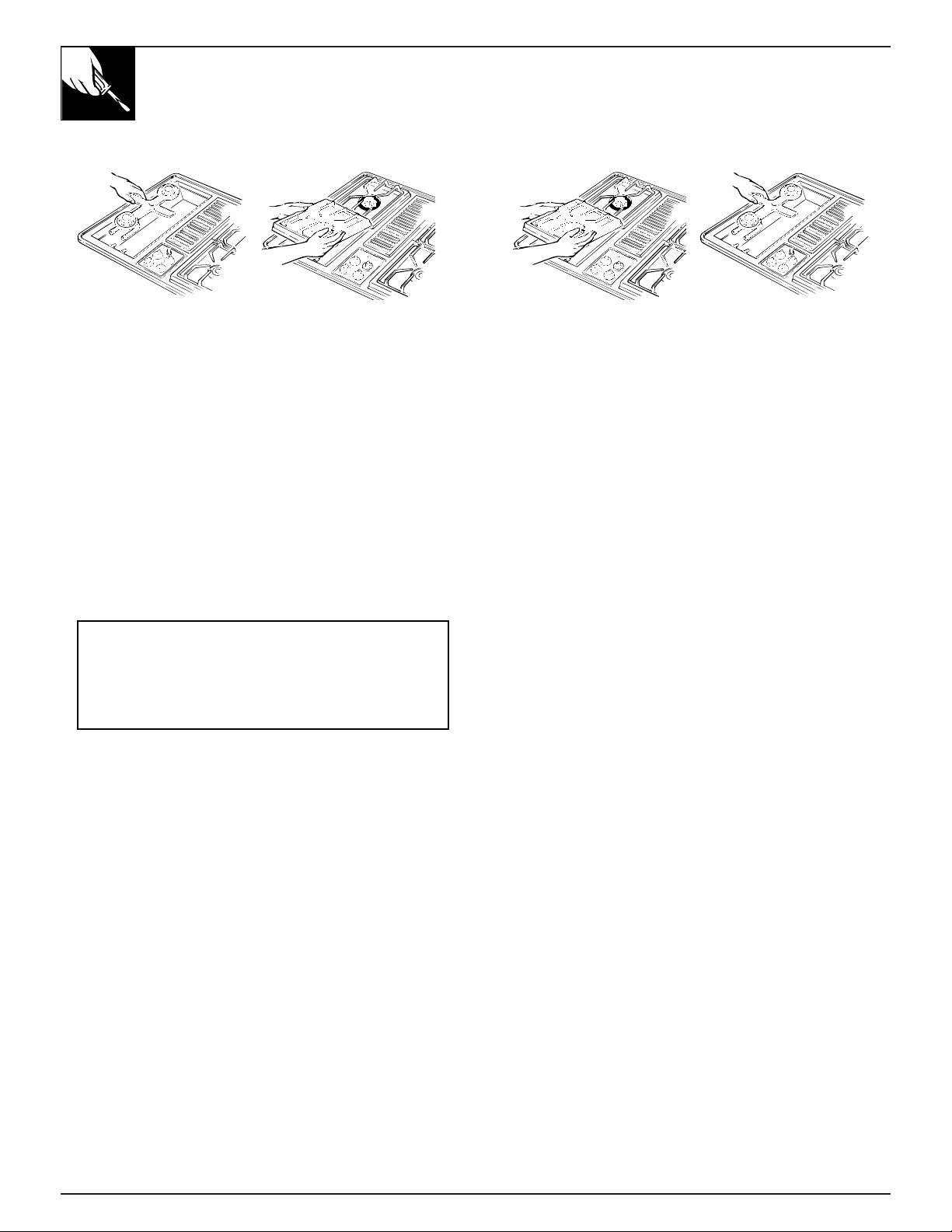
ADJUST LOW FLAME SETTING
1. Light the top burners and continue turning
all of the surface knobs to LOW.
2. Remove all 4 knobs.
3. With a small flat blade
screwdriver, turn the
valve set screws
clockwise to decrease
flame size,
counterclockwise to
increase flame size.
Adjust until the flame is
about the same height as
the top of the burner.
4. Replace the knobs.
7
CHECK QUALITY OF FLAMES
The combustion quality of burner flames needs
to be determined visually.
If burner flames look like (A), call for ser vice.
Normal burner flames should look like (B) or
(C), depending on the type of gas you use.
With LP gas, some yellow tipping on outer
cones is normal.
8
CONVERT GRILL BURNER AIR SHUTTER
(on some models)
The left hand air shutter controls the rear half of
the grill burner; the right hand shutter controls
the front half.
Slide air shutter backward or forward to increase
or decrease the size of the air opening. Air shutters
fit snugly on the grill burner, so a screwdriver
blade may be required to make this adjustment
(see illustration). The snug fit of the air shutter
assures it will remain positioned correctly.
5
Air Opening
To Open
Air Shutter
Insert screwdriver blade in slot and
twist with slight pressure to allow air
shutter to slide easily.
To Close
(A) Yellow flames—Call for service
(B) Yellow tips on outer
cones—Normal for LP gas
(C) Soft blue flames—Normal for
natural gas
Valve
Stem
Clockwise
to reduce
flame size.
Counterclockwise
to increase
flame size.
Page 30

QUESTIONS?
USE THIS PROBLEM SOLVER
PROBLEM POSSIBLE CAUSE
BURNERS DO • Make sure electrical plug is plugged into a live power outlet.
NOT LIGHT
• Check for a blown circuit fuse or a tripped main circuit breaker.
• Check to be sure igniter is clicking. If igniter doesn’t click, turn control knob
off and clean igniter.
• Check to be sure appliance regulator is set for correct fuel.
• Check to be sure inlet pressure is adequate.
• Burner parts not replaced correctly.
• Check to be sure burner ports or igniter ports are not clogged.
BURNERS HAVE
YELLOW OR
YELLOW-TIPPED
FLAMES
(A) Yellow flames — (B) Yellow tips on outer (C) Soft blue flames —
Call for service cones — Normal for Normal for
LP gas natural gas
• If burner flame looks like (A), call for service. Normal burner flames
should look like (B) or (C), depending on the type of gas.
NOTE: The grill burner will show orange flames from grease drippings.
FLAME IS UNEVEN • Burner ports may be clogged.
• Flame setting may need to be adjusted.
FLAME LIFTS OFF • Shutter on the mixer tube needs to be closed until the flame settles on the
THE PORTS burner ports. See Minor Adjustments You Can Make section in this guide.
BURNER FLAMES VERY • If cooktop is connected to LP gas, check all steps in
LARGE OR YELLOW the Installation Instructions.
BURNER CONTROL • When the knob is at the OFF position, it must be pushed in before it can be
KNOB WILL NOT TURN turned, and it can only be turned in a counterclockwise direction. When the
knob is at any other position, it can be turned in either direction without being
pushed in.
FAN DOES • Fan control knob must be turned in clockwise direction to turn fan on.
NOT WORK
FAN TURNS ON • This is normal. The fan will operate automatically when the grill is in use.
AUTOMATICALLY
If you need more help…call toll free:
GE Answer Center
®
800.626.2000
consumer information service
30
Page 31

Upon request, GE will provide
Braille controls for a variety of
GE appliances, and a brochure
to assist in planning a barrier-free
kitchen for persons with limited
mobility. To obtain these items,
free of charge, call 800.626.2000.
Consumers with impaired hearing or speech who have
access to a TDD or a conventional teletypewriter may
call 800-TDD-GEAC (800-833-4322) to request
information or service.
We’ll Be There
With the purchase of your new GE appliance, receive the assurance that if you ever need
information or assistance from GE, we’ll be there. All you have to do is call—toll-free!
In-Home Repair Service
800-GE-CARES (800-432-2737)
A GE consumer service professional will provide expert repair service,
scheduled at a time that’s convenient for you. Many GE Consumer Service
company-operated locations offer you service today or tomorrow, or at your
convenience (7:00 a.m. to 7:00 p.m. weekdays, 9:00 a.m. to 2:00 p.m. Saturdays).
Our factory-trained technicians know your appliance inside and out—so most
repairs can be handled in just one visit.
GE Answer Center®
800.626.2000
Whatever your question about any GE major appliance, GE Answer Center®
information service is available to help. Your call—and your question— will be
answered promptly and courteously. And you can call any time. GE Answer
Center® service is open 24 hours a day, 7 days a week.
Service Contracts
800-626-2224
You can have the secure feeling that GE Consumer Service will still be there
after your warranty expires. Purchase a GE contract while your warranty is still
in effect and you’ll receive a substantial discount. With a multiple-year contract,
you’re assured of future service at today’s prices.
Parts and Accessories
800-626-2002
Individuals qualified to service their own appliances
can have parts or accessories sent directly to their home.
The GE parts system provides access to over 47,000
parts…and all GE Genuine Renewal Parts are fully
warranted. VISA, MasterCard and Discover cards
are accepted.
User maintenance instructions contained in this guide
cover procedures intended to be performed by any user.
Other servicing generally should be referred to qualified
service personnel. Caution must be exercised, since
improper servicing may cause unsafe operation.
For Customers With Special Needs…
800.626.2000
The Problem Solver Consumer Services
Page 32

WHAT IS COVERED
FULL ONE-YEAR WARRANTY
For one year from date of original
purchase, we will provide, free of
charge, parts and service labor in
your home to repair or replace
any part of the cooktop
that fails
because of a manufacturing defect.
***********************
This warranty is extended to the
original purchaser and any
succeeding owner for products
purchased for ordinary home use in
the 48 mainland states, Hawaii and
Washington, D.C. In Alaska the
warranty is the same except that it is
LIMITED because you must pay to
ship the product to the service shop
or for the service technician’s travel
costs to your home.
All warranty service will be provided
by our Factory Service Centers or by
our authorized Customer Care
®
servicers during normal working hours.
Should your appliance need service,
during warranty period or beyond, call
800-GE-CARES (800-432-2737).
WHAT IS NOT COVERED
• Service trips to your home to teach
you how to use the product.
Read your Use and Care material.
If you then have any questions
about operating the product,
please contact your dealer or our
Consumer Affairs office at the
address below, or call, toll free:
GE Answer Center
®
800.626.2000
consumer information service
• Improper installation.
If you have an installation problem,
contact your dealer or installer.
You are responsible for providing
adequate electrical, gas, exhausting
and other connecting facilities as
described in the Installation
Instructions provided with the
product.
• Replacement of house fuses or
resetting of circuit breakers.
• Failure of the product if it is used for
other than its intended purpose or
used commercially.
• Damage to product caused
by accident, fire, floods or acts
of God.
WARRANTOR IS
NOT
RESPONSIBLE FOR
CONSEQUENTIAL DAMAGES.
Some states do not allow the exclusion or limitation of incidental or consequential damages, so the above limitation or exclusion
may not apply to you. This warranty gives you specific legal rights, and you may also have other rights which vary from state to state.
To know what your legal rights are in your state, consult your local or state consumer affairs office or your state’s Attorney General.
Warrantor: General Electric Company
If further help is needed concerning this warranty, write:
Manager—Consumer Affairs, GE Appliances, Louisville, KY 40225
JGP18
JGP389
YOUR GE COOKTOP
WARRANTY
Staple sales slip or cancelled check
here. Proof of original purchase date
is needed to obtain service
under warranty.
 Loading...