

Page 1
Installation
Built-In TrimKits
JX2127andJX2130
Instructions
Questions?Call GEAnswer Centerat 800.626.2000or Visitore-X_bsite_,t:www.GEAppliances.com ]
BEFORE YOU BEGIN
Read these instructions completely and carefully.
• IMPORTANT - S_,,'ethese
instructions ti)r local inspector's use.
• IMPORTANT - Obsei.e_,ll
governing codes and ordinances.
• Note to Installer - Be sure to leave these
instructions with the Consun]er.
• Note to Consumer - Keep these instructions
ti)r fllture reterence.
• For easier installation and peisonal satet,i, we
reconnnend that two people install this microwave oven.
" Unplug the microwave ()veil beti)re attempting
installation of this kit.
FOR YOUR SAFETY:
A WARNING - Be*,iebeginning the
installation, switch power off at service panel and lock
tile service disconnecting means to prevent power
fl'om being switched on accidentally. When the service
disconnecting means cannot be locked, securely thsten
a i)r()minent warning device, such as a tag, to the
service panel.
Skill level - Installation of this appliance requires basic
mechanical and electrical skills.
• Completion time - 1-3 hours
• Proper installation is the responsibility of the installer,
" Product tailure due to imi)roper installation is not
covered under the Warranty.
This kit is UI, listed for installation alone or over
an) General Electric/Hotpoint/RCA single electric
wall OX ell.
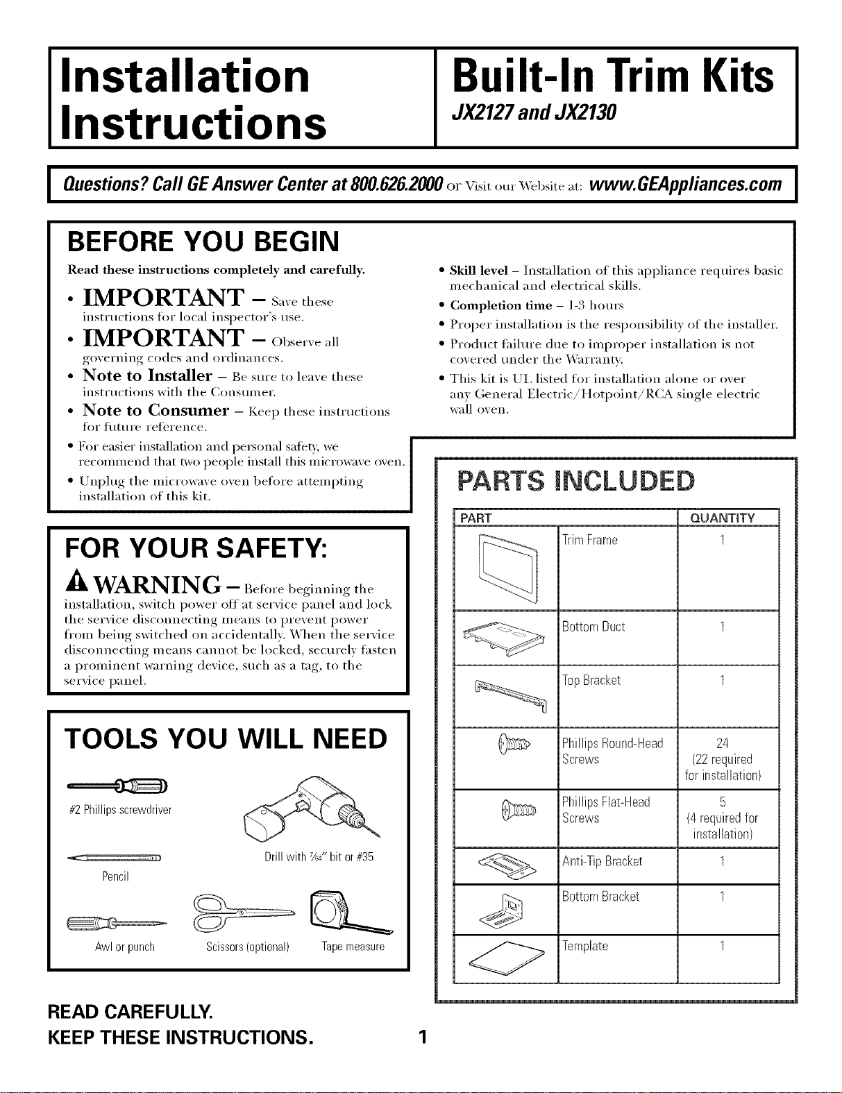
PARTS mNCLUDED
PART QUANTITY
Trim Frame 1
Bottom Duct 1
Top Bracket 1
TOOLS YOU WILL NEED
#2Phillipsscrewdriver
Drill with 7_64Hbit or#35
Pencil
Awl or punch
READ CAREFULLY.
KEEP THESE INSTRUCTIONS.
Scissors(optional) Tapemeasure
Phillips Round-Head 24
Screws (22 required
for installation)
Phillips Flat-Head 5
Screws (4 required for
installation)
Anti-Tip Bracket 1
Bottom Bracket 1
Template 1
Page 2
Installation Instructions
CUTOUT DiMENSiONS
Models
Height
Width
Depth (nfin.)*
* Min. depth with rece
Min. depth with rece
1%"overlap ...........
1" Clearancebeyond 1" overlap
19½" or 22"
)ta(le Olltside (;tbii/et QI 9"
m_(le inside _abinet 22"
TrimFrame
(onall sides)
27"
16%"
25½"
30"
16:_"
25½"
19½" or 22"
1.½
Depth
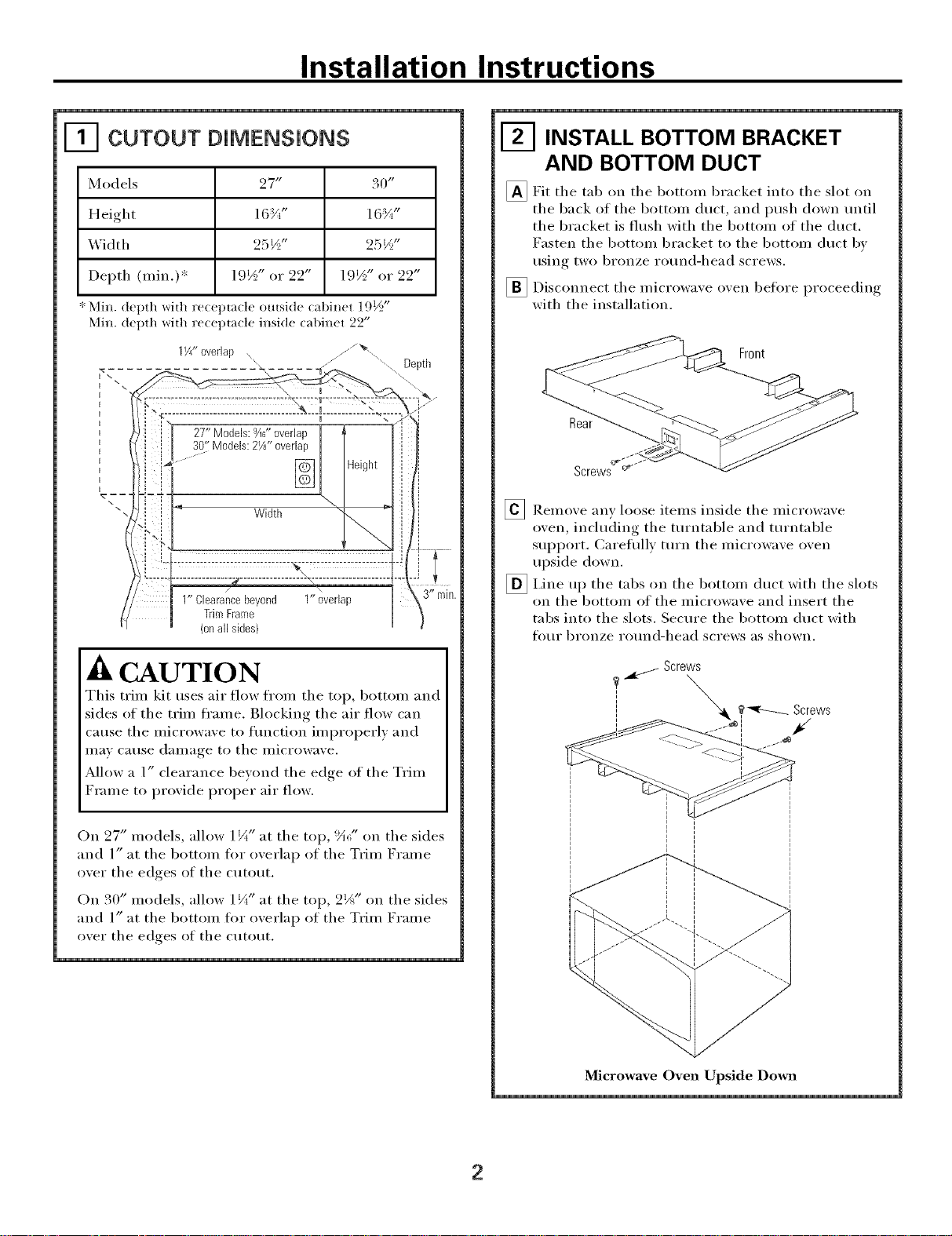
INSTALL BOTTOM BRACKET
AND BOTTOM DUCT
_Fit tile tab tile bottom bracket tile slot
(111 oil
tile back of tile 1)ottom duct, and push down tmtil
tile bracket is flush with tile bottom of tile duct.
Fasten tile bottom bracket to tile bottom duct b_
rising two bronze ro/ind-head screws.
_ Disconnect tile microwa',e o',en 1)elore _roceeding
with tile installation.
Screws
_ Remove any loose items inside tile microwave
oven, including tile turntable and turntable
support. Careflfllv tm'n tile microwave oven
upside down.
_ I,ine tile tabs tile bottom duct with tile slots
lip
Oil
on tile bottom of tile microwave and insert tile
tabs into tile slots. Secm'e the bottom duct with
four bronze ro/md-head screws as shown.
into
I ,
Front
A CAUTION
This trim kit uses air flow fl'om tile top, bottom and
sides of tile trim frame. Blocking tile air flow can
cause tile microwave to flmction improperly and
Ill,IV C_ltlSe dalllage to tile illicYowave.
Allow a 1" clearance beyond tile edge of tile Trim
Frame to provide proper air flow.
On 27" models, allow 1 i/_,, at tile top, !_;" on tile sides
and l" at tile bottom for oxerlap of tile Trim Frame
oxer tile edges of tile cutout.
On 30" models, allow l ¼ at tile top, 2JA" on tile sides
and l" at tile bottom for oxerlap of tile Trim Frame
oxer tile edces of tile cutout.
l zt
Microwave Oven Upside Down
2
Page 3

mnstaJiation mnstructions
F_ iNSTALL THE ANTbTJP BRACKET
[_ l_)raw a lim_e o]_ the cutola {loot at the ce]_ter of
the claouL amid exteN_d the lim_e _" dow_ the f_ce
of the cabim_et.
_Fo]d or c_t the f_ont edge of the template, a](mg
the {_ont g_fide ]h_e_ Place the template fi_sh
aiding the f_<mt edge of the cl_tol_t floo_; a]]gn]m_g
the cellter ]im_e of the template _it]l the cellter ]im_e
of the clltoIlt {loot. Mark the cel/ters of the t_ko
scre_ holes _ith am_ a_] or ce_ter preach f_)r the
am_ti-ti I) bracket ]ocatiol_ as showl_.
//
Cutout Floor
[]Remove the template amid drill two holes for the
Screws
1-_ INSTALL MICROWAVE OVEN
INTO CABINET
[_ Slide [lie microwa',e o',en part wa_ into [lie cabinet
Dizening.
[]Plug in the microwaxe oxen.
Bottom Duct sernbly
Anti-Tip
Bracket
Bottom Bracket
The bottom bracket must be fiat to the cutout
[]
floor to engage correctly with the anti-tip bracket
as shown. Carefllllv slide the microwave oven back,
engaging the anti-tip bracket. Make sure the
power cord is not mashed or cut as you slide the
microwave into place.
Center the microwaxe oxen within the
[]
ct/to/It ol)ening,.
Ensure the microwaxe o_en is accurately centered.
[]
I,ine up the center line on the cabinet with the
triangular hole on the front of the bottom duct,
' I
[] Ira/stall the bracket the flooram/[i-[ip
Hsi_/ _ two bro_/ze roH_/d-]/ead screws.
Anti-Tip Bracket
(H/[O CIKtHK
Opening
Screws _"
\ Flange
_ Drill pilot holes through the positioning flange
and then install fixe bronze round-head screws
at the front of the bottom duct as shown.
3
Page 4

mnstaJiation mnstructions
I-_ INSTALL THE TOP BRACKET
_ Place die t(_}:) bracket on t]_e u_p of die microwave
ovem widl die tabs (m die U_p and sides or the
bracket tittim/g s(Hua_'e]_, agaim/st_, the microwave oven.
Tabs
Screws
_ l_)ri]] pilot boles t]/x'ol_gh the holes ira/ the top
b_'ackeL _ttach the top b_'acket to the cabim/et
Hsim/ 7-_/im/e bFtim/ze i'()Hm/d-]/ead scFev,'s.
I-_ INSTALL THE TRIM FRAME
_ Pla('e trim h'ame oxer microwaxe oxen.
_Snap tile two s )ring clips on tile trim frame intoI ,
_Open tile microwaxe oxen door. Secure tile trim
tile tile
tile slots on tile top bracket.
"Spring Clips
frame usiw, Ibm" fiat-head screws (two on tile
inside top and two on the inside bottom).
Flat-head screws
164D3370P328 ]
49-40398
064).I,JR
Flat-head screws
REPLACE ANY LOOSE ITEMS
_Yom" trim kit is now flfllv installed. Replace any
loose items that were remoxed fl'om tile inside
of tile mi(rowaxe oxen. Saxe or discard tile extra
screws. Do not place them in tile microwaxe o;en.
_Keep these installation inst_ uctions for flmue
i'etei'ellce.
_ Replace house fllse or close circuit breaker to
restore power at the set\ice panel.
4
Printed in Korea
 Loading...