

GE JBP35DM4WW, JBP35SD1SS, JBP35DM4CC, JBP35SIM6SS, JBP35DIM5WW Installation Instructions Manual
...Page 1
Installation Instructions
Free-Standing Electric Ranges
Questions? CaFI1.800.GE.CARES(1.800.432.2737) or visit www.GEAppliances.com
In Canada, call 1.800.561.3344 or visit www.GEAppliances.ca
BEFORE YOU BEGIN
Readthese instructionscompletely and
carefully.
" IM PO RTANT -- Savetheseinstructions
for local inspector's use.
" IMPORTANT -- Observeall
governingcodesand ordinances.
, Note to Installer- Be sure to leave these
instructions with consumer.
, Note to consumer - Keep these
instructions for future reference.
, Skill level- Installation of this appliance
requires a qualified installer or electrician.
, Proper installation is the responsibility of the
installer.
• Product failure due to improper installation is
not covered under warranty.
FOR YOUR SAFETY:
T_-Over Hazard
• A child or adult can tip the range and be killed.
• Install the anti-tip bracket to the wall or floor.
Engage the range to the anti-tip bracket by sliding the
range back such that the foot is engaged.
Re-engage the anti-tip bracket if the range ismoved.
Failure todo so can result in death or serious burns
to children or adults.
If you didnot receive an anti-tip bracketwith your purchase,
call 1.800.626.8774to receive one at no cost. (inCanada,
call 1.800.56!.3344.) Forinstallation instructions of the bracket,
visit: www.GEAppliances.com.(In Canada, www.GEAppliances.ca.)
Anti-Tip Bracket
Kit Included
_,WARNING Beforebeginningthe
installation, switch power off at service
panel and lockthe service disconnecting
means to prevent power from being
switched on occidentally. When the
service disconnecting means cannot
belocked, securely fasten a prominent
warning device, such asa tag, to the
service panel.
MATERIALS YOU MAY NEED
Power CordClamp "_
SqueezeConnector (ULListed40 AMP)
(ForConduit 3-Wire Cord 4'
Installations Only) long
StrainRelief
TOOLS YOU WILL NEED
Drill with 1/8"Bit Tin Snips
Safety Glasses Tape Measure
Adjustable Wrench Pliers
Level Z/4" Nut Driver
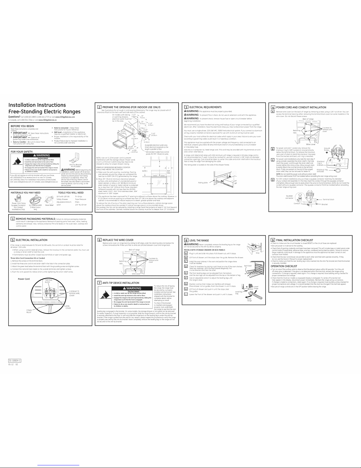
PREPARE THE OPENING (FOR INDOOR USE ONLY)
Seeillustrations for allrough-in and spacing dimensions. Therange may be placed with 0"
clearance (flush)at the back wall and side walls of the cabinet.
On models with baking 2-1/2"
30"
or warming drawers,
i 76.2cm
electrical outlet must J "'_
be in this area. i
,, 25" !
j 63.5cm _'2-1/2"
j ....=4 6.35cm
iT"
78cm
14-1/2"
NOTE:Use a a' (1.22m)power cord to prevent
interference with the storage drawer. Power cords
4-1/2' (1.37m)to 6' (1.83m) long may have to be
dressed to allow for proper drawer closing.
MINIMUM DIMENSIONS BETWEEN COOKTOP,
WALLS AND ABOVE THE COOKTOP:
A. Makesure the wall covering, countertop, flooring
and cabinets around the range can withstand the
heat (up to 200°F [93.3°C])generated by the range.
B.Allow 30"(76.2cm) minimum clearance between
surface units and bottom of unprotected wood or
metal cabinet, or allow a 24" (60.96cm) minimum
when bottom of wood or metal cabinet isprotected
by no lessthan 1/4" (.635cm) thick flame retardant
millboard covered with not lessthan No 28 MSG
sheet metal, (.015'1,.015"thick stainless steel, .024"
aluminum or .020" copper.
7-&/2"
j 19.0Scm
10.16cm
Acceptableelectrical outlet area.
Orientelectrical receptacle sothe
length isparallel tofloor.
* GE-brandedmodelshave control
panels30-7/8" (78.42cm) wide.
NOTEC
C.This appliance has been approved for 0" spacing to adjacent surfaces above the cooktop. However, a
B"(15.24cm) minimum spacing to surfaces less than 15"(38icm) above the cooktop and adjacent
cabinet is recommended to reduce exposure to steam, grease splatter and heat.
To reduce the risk of burns orfire when reaching over hot surface elements, cabinet storage space
above the cooktop should be avoided. Ifcabinet storage space is to beprovided above
the cooktop, the risk can be reduced by installing a range hood that projects atleast 5" (12.7cm)beyond
the front ofthe cabinets. Cabinets installed above the cooktop must be no deeper than 13" (33.02cm).
[TI ELECTRICAL REQUIREMENTS
_WARNING This appliance must be properly grounded.
AWARNING To prevent fire or shock, do not use an extension cord with this appliance.
_,WARN[ NG To prevent shock, remove house fuse oropen circuit breaker before
beginning installation.
We recommend you have the electrical wiring and hookup of your range connected by aqualified
electrician. After installation, have the electrician show you how to disconnect power from the range.
You must use a single-phase, 220-240 VAC, 50/60 hertz electrical system. If you connect to aluminum
wiring, properly installed connectors approved for use with aluminum wiring must be used.
Check with your local utilities for electrical codes which apply in your area. Failure to wire your oven
according to governing codes could result ina hazardous condition.
This appliance must be supplied with the proper voltage and frequency, and connected to an
individual, properly grounded, 40 amp (minimum) branch circuit protected by acircuit breaker
or time-delay fuse.
Use only a 3-conductor UL-listed range cord. This cord may be provided with ring terminals on wire
and a strain relief device.
A range cord rated at 40 amps with 250 minimum volt range is required. A 50 amp range cord is
not recommended but ifused, it should be marked for use with nominal 1-3/8" (3.49 cm)diameter
connection openings. Care should betaken to center the cable and strain relief within the knockout
hole to keep the edge from damaging the cable.
The rating plate islocated on the side of the drawer frame.
Rating@ate
POWER CORD AND CONDUIT INSTALLATION
Remove wire cover (onthe back of range) by removing screws using a 1/4" nut driver. Youcan
access the terminal block by either removing the terminal block cover (onsome models) or the
wire cover. Do not discard these screws.
Back of range
Reds0/!_ ']}ning < 5 screws to
wire
cover
Wirecover
r_ For power cordand r' conduit only, remove the
knockout ring (1-3/8")located on bracket directly
below the terminal block. To remove the knockout,
use a pair of pliers to bend the knockout ring away
from the bracket and twist until ring is removed.
Forpower cord installations only (seethe next step if
using conduit),assemble the strain relief in the hole.
Insert the power cord through the strain relief and
loosely tighten the clamp screw. Allow enough slack
to easilyattach the cord terminals to the terminal
block. Iftabs are present at the end of the winged
strain relief, they canbe removed for betterfit.
NOTE;Donot installthe power cordwithout a strain relief.
F61
Ground.......
Screw lfd4_ztTl4o _@br_
it-, 0
Knockout ring ___
removed
Thestrain reliefbracket MUSTbeinstalledbefore reinstallingthe rear rangewiring cover.
For3/4" conduit installations only, purchase a squeeze connector matching the diameter
ofyour conduit andassemble it inthe hole. Insertthe conduit through the squeezeconnector
and tighten.Allow enoughslack to easilyattach the wiresto the terminal block.NOTE:Donot installthe
conduit without asqueeze connector. The squeeze connector MUSTbe installed before reinstalling
the rear range wiring cover.
Squeeze
connector
-- Terminal block
Bracket
REMOVE PACKAGING MATERIALS: Failureto remove packagingmaterials
couldresultindamage to theappliance.Remove allpackingpartsfromoven,rocks,heating
elementsand drawer.Also,removeprotectivefilmand labelson theouterdoor,cooktopand
control panel.
r_ ELECTRICAL INSTALLATION
If the range is rated between 8,750 and 16,500 watts, the cord kit or conduit must be rated for
40 amps - 250 volts.
. When using acord kit rated 40 amps, remove the knockout inthe connection @ate. You must use
a clamp or strain relief to hold the cord.
• Terminations must be either closed loop terminals or open end spade lugs.
Three-Wire Cord Connection Kit or Conduit
1.Remove the screws onthe terminal block.
2. Installthe three-wire cord kitand strain relief inthe hole inthe connection plate.
3. Attach the greenlead below the terminal block with the grounding screw and tighten screw.
4. Connect the red and blackleads to the outside terminals and tighten screws.
5. Pushthe cord upward (to relievestrain), while tightening the strain relief clamp.
Power Cord
! _11 II_H_H_llI I II- sSCREWSTO
III _1/_\i_ REHOVEWIRE
CO ER
STRAIN
RELIEF
[_ REPLACE THE WIRE COVER
Replacewire cover on range back by sliding its left edge underthe retaining tabs and replace the
screws removed earlier.Make surethat no wires are pinched between cover and range back.
Back of range
5 screws to
cover
Wire
ITI ANTI-TIP DEVICE INSTALLATION
Tip-Over Hazard
, Achild or adult cantip the rangeand bekilled.
Installthe anti-tip bracket to thewall or floor.
Engagethe rangeto the anti-tip bracketby slidingthe
rangeback suchthat the foot isengaged.
, Re-engagethe anti-tip bracket ifthe rangeis moved.
, Failure todo socan resultin death orserious burns
to childrenor adults.
To reducethe riskof tipping
the range,the range must
be securedby a properly
installed anti-tip bracket. See
installation instructions
shipped with the bracket for
complete details before
attempting to install.
To checkif the bracket
is installedand engaged
properly, look underneath
the range to seethat the rear
leveling leg isengaged inthe bracket. Onsome models, the storage drawer or kick panel can be removed
for easier inspection. If visualinspection is not possible, slidethe range forward, confirm the anti-tip bracket
is securely attached to the floor orwall and slidethe range back so the levelingleg is under the anti-tip
bracket, if the range ispulled from thewall for any reason, always repeat this procedure to verify the range
is properly secured bythe anti-tip bracket. Nevercompletely remove the levelinglegs or the range will not
be secured tothe anti-tip bracket.
_LEVELTHE RANGE
_,WARNI NG Nevercompletelyremove thelevelinglegastherange
willnotbesecuredtotheanti-tipdeviceproperly.
MODELS WITH STORAGE DRAWER OR KICKPANELS
r_ Plug in unit and slide into place. Pull drawer out until it stops.
@
F61
Lift front ofdrawer until the stops clear the guide. Remove the drawer.
Installthe oven shelvesin the oven and positionthe rangewhere
itwill be installed.
Check for levelness by placing a spirit level on one of theoven shelves. Spirit level
Taketwo readings-with the level placed diagonally first
in one direction and then the other.
r_ The front leveling legscan beadjusted from the bottom
and the rear legs can be adjusted from the top orthe bottom of leg.
r_ Use an adjustable wrench to adjust the leveling legsuntil
the range is level.
IGI Position cord so that it does not interfere with drawer. /_'//f/_,
Place drawer rail on guides. Push the drawer in until itstops. _l__ Lower
r_ Lift front of drawer and push in until the stops clear "_,
range
the guides, kevelingJ _" r _;_._J
rT] Lower the front of the drawer and push in until it closes.
Raise
range
191 FINAL INSTALLATION CHECKLIST
• Check tomake sure the circuit breaker is closed (RESET)or the circuit fusesore replaced.
• Be surepower is in serviceto the building.
• Check that oil packing materials and tope hove beenremoved. This will include tope on metal panel under
control knobs (if applicable),adhesive tope, wire ties, cardboard and protective plastic.Failure to remove
these materials could result in damage to the appliance once the appliance has beenturned onand
surfaces have heated.
• Check that thedoor and drawerore parallel toeach other and that both operate smoothly. Ifthey
do not, seethe Owner's Manualfor proper replacement.
• Check to makesure that the rear leveling leg isfully inserted intothe AntPTip bracket and that the bracket
issecurely installed.
OPERATION CHECKLIST
•Turn on one ofthe surface units to observethat theelement glows within 60seconds. Turnthe unit
off when glow isdetected. If the glow is notdetected within thetime limit,recheck the range wiring
connections. If change isrequired, retest again. Ifno change is required, havebuilding wiring checkedfor
proper connections and voltage.
• Check that theClock (on models soequipped) display is energized. Ifa series of horizontal red
lines appear inthe display,disconnect powerimmediately. Recheckthe range wiring connections.
Ifchange ismade to connections, retest again. If no change isrequired, have building wiring checked for
proper connections and voltage. It is recommended that the clock be changed if the red linesappear.
• Be sureall range controls are in the OFFposition before leaving the range.
3!-!0824-1
01-12 GE
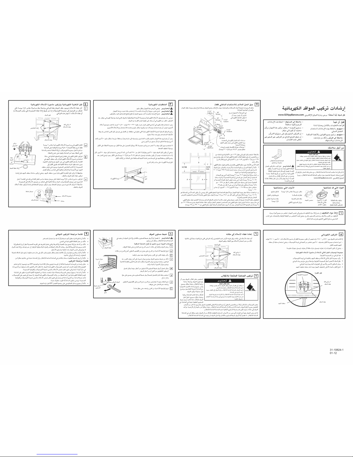
Page 2
iii ........ is
_i _. bat.ai (_. v/^-_)._l t__ _l ,_,z_
._G.L_iC.__:__ t+_a_t_t_l _ i<_. ___di
r-q
r-q
78cm
14-1/2"
NOTEI_
A _
B
c
Both_
Sides
i
.._ J-_,
._i c_ _LUi ([__L#_ _
73L,,.,_ _J,_i a[ ,_,._,..,Ji _i.7._1 a[ _1 ..,,-4 LeA,z-JIJ'_0 "-<e-'''I=>_1
.L,U,._b _..._._1J_.,_a._
€.
www.GEAppliances.com :_a_yl _._i s._D _->_. s__b_i _ei _.d
._.+._,.:,._q_#.[&,_.,,.u
._t#__,_ll___oI_L_ _1
_LIA_J _.AL_I _t-_JI
._i_i_._._i_ _,c.>@i
www.GEAppliances.com :_a__KJ_l __i_!1
.c_____u _._ _/^ _L_ _._ _ _
Jail _ .t.-D.N_..,.._ _ _.,.JJ,.:.>L>U_
(,,,,_i _.)D+-.-5.
l.._L_ .t_.b
(_.__c.:_Jt__#)
..,.,_L,.,_lJilt # _ ,c,iai(de.,.,_," " .._i) _ _,ol_ilc._l_L;Gi_(_: ,,
_t.;:z,eaia!.t4.-_..__ OFFq.Z._i_ __ 60J:_ ._._ _1A,f _{z_ "<,,e------_lol_...al,._ _,_la J_ ,,
_7'&'/_-2"JIc_ _,"_ "lm'=>-'_JI7<=C_7t t,.,,_,=,._l_ _ o,,._L2_ 13S ,2dL,_ (o'S, tea _1 €,,,,,,_.4e_._.,,..?,._.) 7__.L,.,,JIj,,._L •
._dl <D__ OFF &_dl "-_-_a _ o _ e,-K--_IJ_t_a _ Oj _ •
.._ <._.._.la
.,_.i.i.&__ _ J._l,.dl _ ,oG_l a
._,_i _._..__%_
7_, .,,.,,LDI .-!1 _L_ 131 L._,._!J
,.Z_ ai _ _.L_,.z,,,I_ .c,__e,-,=,.._lk=..# ,.D.l_,.._i G,, o-_£_ -0ee. [f-" _ .Dd-ll b- _--t_ fJ,.._l _1 .
.,_i_Ji-_a "-_ee-.oL_I ,=,L_.d=JioA[<._Tb.>_tTI "C,.Z_______IJ_ ,f,
_<z.U,.,Jf _L,t_
31-10824-1
01-12
 Loading...