

Page 1
Installation instructions
Free-Standin Electric Ran es
Questions? Call 1-800-GE-CARES (1-800-432-2737) or visit www.geappliances.com
In Canada, call 1-800-561-3344 or visit www.geappliances.ca
BEFORE YOU BEGIN
Read these instructions completely and
carefully.
" IMPORTANT -- Save these
instructions for local inspector's use.
" IMPORTANT -- Observeall
governing codes and ordinances.
, Note to Installer- Be sure to leave these
instructions with consumer.
FOR YOUR SAFETY:
• All ronges can tip.
• BURNS or other SERIOUS
INJURIES con result.
• INSTALL and CHECK the
ANTI-TIP brocket following
the instructions supplied
with the brocket.
If you did not receive an anti-tip bracket with your purchase,
call 1-800-626-8774 to receive one at no cost. (In Canada,
call 1-800-561-3344.) For installationinstructionsof the bracket,
visit: www.geappliances.com. (In Canada, www.geappliances.ca.)
MATERIALS YOU MAY NEED TOOLS YOU WILL NEED
Squeeze Connector (UL Listed 40 AMP) Level 1/4" Nut Driver
(For Conduit 4-Wire Cord 4' long OR
Installations Only) 3-Wire Cord 4' long
r-_ REMOVE PACKAGING MATERIALS: Failuretoremove packaging
materials could result in damage to the appliance. Remove all packing parts from oven,
racks, heating elements and drawer. Also, remove protective film and labels on the outer
door, cooktop and control panel.
Note to consumer- Keep these
instructions for future reference.
, Skill level - Installation of this appliance
requires a qualified installer or electrician.
, Proper installation is the responsibility of the
installer.
o Product failure due to improper installation is
not covered under warranty.
WARN ING -- Before
beginning the installation, switch
power off at service panel and
lock the service disconnecting
means to prevent power from
Anti-Tip Bracket
Kit Included
being switched on accidentally.
When the service disconnecting
means cannot be locked,
securely fasten a prominent
warning device, such as a tag,
to the service panel.
Safety Glasses Tape Measure
Drill with 1/8" Bit Tin Snips
Adjustable Wrench Pliers
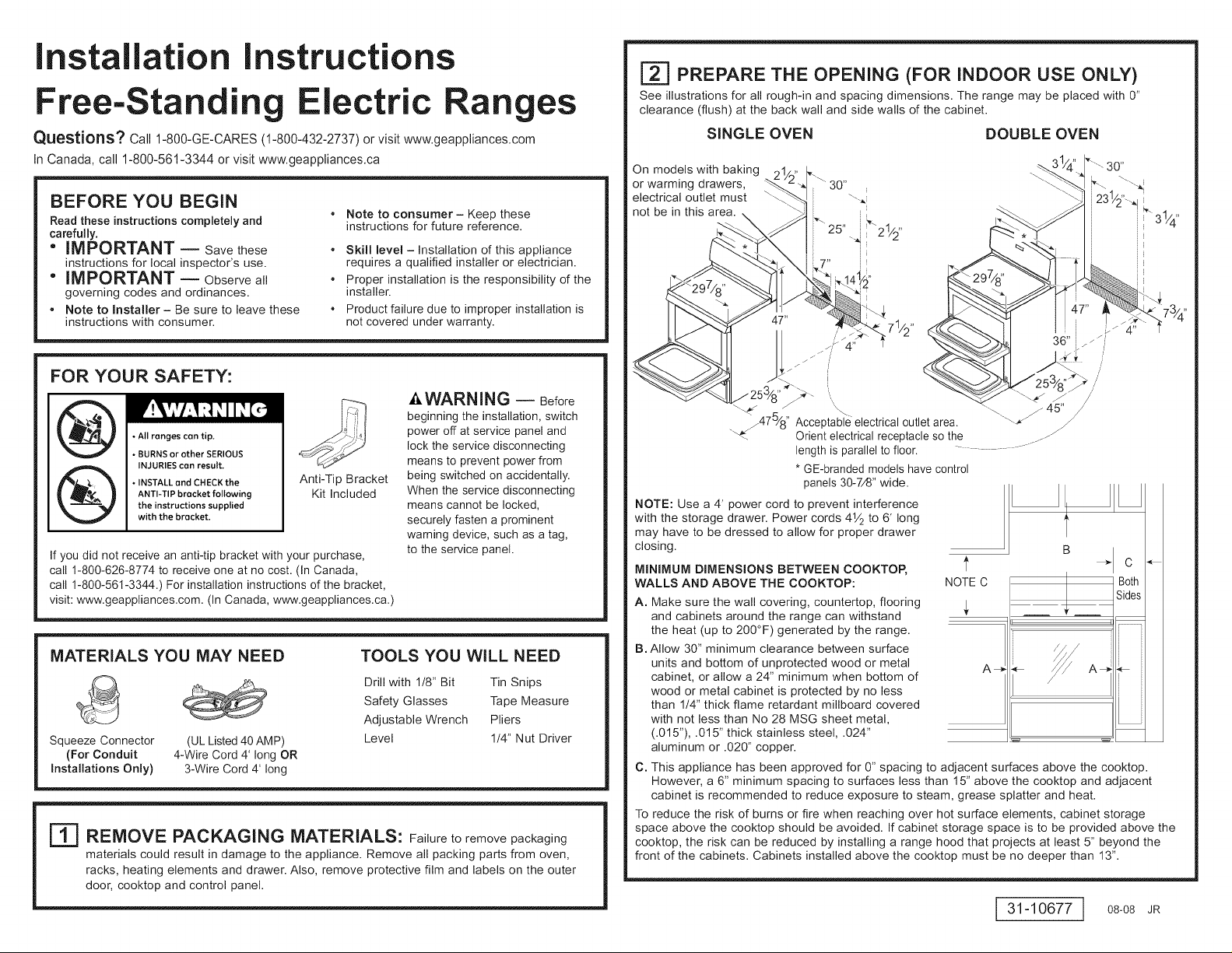
[_ PREPARE THE OPENING (FOR INDOOR USE ONLY)
See illustrations for all rough-in and spacing dimensions. The range may be placed with 0"
clearance (flush) at the back wall and side walls of the cabinet.
SINGLE OVEN DOUBLE OVEN
On models with baking
or warming drawers,
electrical outlet must
not be in this area.
,,JJ 30,,iljjJi
/'
/
\_.,_ .. "--_. / 45" /
. j475/8 '' Acceptable electrical outlet area. '-_
NOTE: Use a 4' power cord to prevent interference
with the storage drawer. Power cords 41/2 to 6' long
may have to be dressed to allow for proper drawer
closing.
MINIMUM DIMENSIONS BETWEEN COOKTOP,
WALLS AND ABOVE THE COOKTOP:
A. Make sure the wall covering, countertop, flooring
and cabinets around the range can withstand
the heat (up to 200°F) generated by the range.
B. Allow 30" minimum clearance between surface
units and bottom of unprotected wood or metal
cabinet, or allow a 24" minimum when bottom of
wood or metal cabinet is protected by no less
than 114"thick flame retardant millboard covered
with not less than No 28 MSG sheet metal,
(.015"), .015" thick stainless steel, .024"
aluminum or .020" copper.
C. This appliance has been approved for 0" spacing to adjacent surfaces above the cooktop.
However, a 6" minimum spacing to surfaces less than 15" above the cooktop and adjacent
cabinet is recommended to reduce exposure to steam, grease splatter and heat.
To reduce the risk of burns or fire when reaching over hot surface elements, cabinet storage
space above the cooktop should be avoided. If cabinet storage space is to be provided above the
cooktop, the risk can be reduced by installing a range hood that projects at least 5" beyond the
front of the cabinets. Cabinets installed above the cooktop must be no deeper than 13".
Orient electrical receptacle so the ....z
length is parallel to floor. .............
* GE-branded models have control
panels 30-7/8" wide.
NOTE C
A_
/
B _ C
Sides
Both
i
i
i
i
i
i
i
J
J
i
31-10677 ] 08-08 JR
Page 2
E_ ELECTRICAL REQUIREMENTS
It,WARNING: This appliance must be properly grounded.
_,WARN ING: All new constructions, mobile homes, recreational vehicles and installations
where local codes do not allow grounding through neutral, require a 4-conductor UL-listed range cord.
WARNING: To prevent fire or shock, do not use an extension cord with this appliance.
_, WARNING: To prevent shock, remove house fuse or open circuit breaker before
beginning installation.
We recommend you have the electrical wiring and hookup of your range connected by a qualified
electrician. After installation, have the electrician show you how to disconnect power from the
range.
You must use a single-phase, 120/208 VAC or 120/240 VAC, 60 hertz electrical system. If you
connect to aluminum wiring, properly installed connectors approved for use with aluminum wiring
must be used.
Effective January 1, 1996, the National Electrical Code requires that new construction (not
existing) utilize a 4-conductor connection to an electric range. When installing an electric range
in new construction, mobile home, recreational vehicle, or an area where local codes prohibit
grounding through the neutral conductor, refer to the section on four-conductor branch circuit
connections.
Check with your local utilities for electrical codes which apply in your area. Failure to wire your
oven according to governing codes could result in a hazardous condition. If there are no local
codes, your oven must be wired and fused to meet the National Electrical Code, NFPA No.
70 - latest edition, available from the National Fire Protection Association.
This appliance must be supplied with the proper voltage and frequency, and connected to an
individual, properly grounded, 40 amp (minimum) branch circuit protected by a circuit breaker
or time-delay fuse.
Use only a 3-conductor or a 4-conductor UL-listed range cord. These cords may be provided with
ring terminals on wire and a strain relief device.
A range cord rated at 40 amps with 125/250 minimum volt range is required. A 50 amp range
cord is not recommended but if used, it should be marked for use with nominal 13/8'' diameter
connection openings. Care should be taken to center the cable and strain relief within the
knockout hole to keep the edge from damaging the cable.
The rating plate is located on the oven frame or on the side of the drawer frame.
SINGLE OVEN DOUBLE OVEN
Rating plate __
Rating
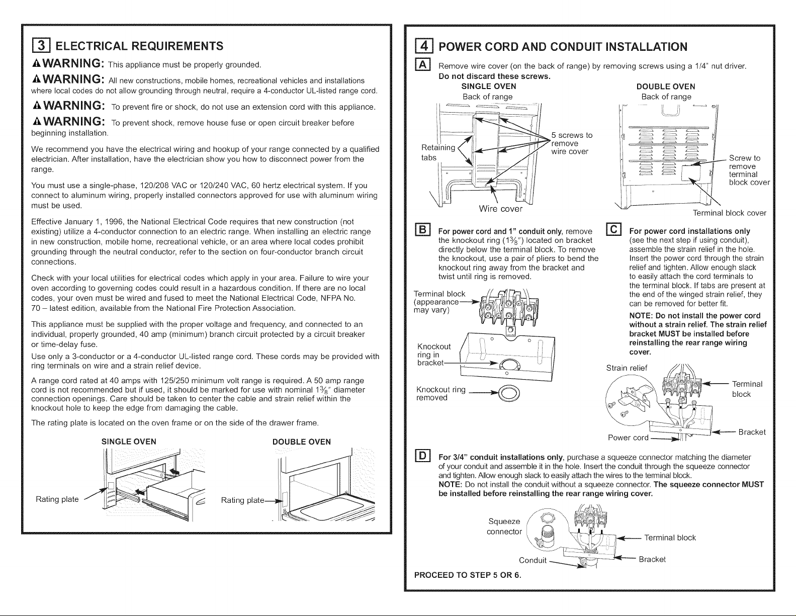
| POWER CORD AND CONDUIT INSTALLATION
I-A-] Remove wire cover (on the back of range) by removing screws using a 1/4" nut driver.
Do not discard these screws.
SINGLE OVEN
Back of range
Wire cover
@
For power cord and 1" conduit only, remove
the knockout ring (13/8") located on bracket
directly below the terminal block. To remove
the knockout, use a pair of pliers to bend the
knockout ring away from the bracket and
twist until ring is removed.
Terminal block __./__ _-__.
(ap peara nce_(_'_ ),_JIQl_tfb'7y_:_#
bracket _
Knockout ring __@removed
5 screws to
wire cover
DOUBLE OVEN
Back of range
, o f
Terminal block cover
For power cord installations only
(see the next step if using conduit),
assemble the strain relief in the hole.
Insert the power cord through the strain
relief and tighten. Allow enough slack
to easily attach the cord terminals to
the terminal block. If tabs are present at
the end of the winged strain relief, they
can be removed for better fit.
NOTE: Do not install the power cord
without a strain relief. The strain relief
bracket MUST be installed before
reinstalling the rear range wiring
cover,
Strain relief _
/:_5__(-_ Terminal
_ Screw to
remove
terminal
block cover
ock
_____._°_:_.,-_C_ J_----- Bracket
@
For 3/4" conduit installations only, purchase a squeeze connector matching the diameter
of your conduit and assemble it in the hole. Insert the conduit through the squeeze connector
and tighten. Allow enough slack to easily attach the wires to the terminal block.
NOTE: Do not install the conduit without a squeeze connector. The squeeze connector MUST
be installed before reinstalling the rear range wiring cover.
PROCEED TO STEP 5 OR 6.
block
Page 3
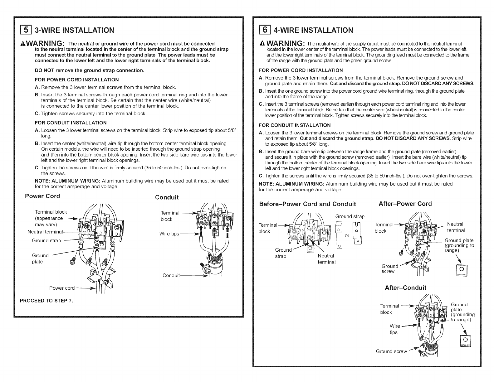
[_ 3-WIRE INSTALLATION
[_ 4-WIRE INSTALLATION
Z_WARN ING: The neutral or ground wire of the power cord must be connected
to the neutral terminal located in the center of the terminal block and the ground strap
must connect the neutral terminal to the ground plate. The power leads must be
connected to the lower left and the lower right terminals of the terminal block.
DO NOT remove the ground strap connection.
FOR POWER CORD INSTALLATION
A. Remove the 3 lower terminal screws from the terminal block.
B. Insert the 3 terminal screws through each power cord terminal ring and into the lower
terminals of the terminal block. Be certain that the center wire (white/neutral)
is connected to the center lower position of the terminal block.
C. Tighten screws securely into the terminal block.
FOR CONDUIT INSTALLATION
A. Loosen the 3 lower terminal screws on the terminal block. Strip wire to exposed tip about 5/8"
long.
B. Insert the center (white/neutral) wire tip through the bottom center terminal block opening.
On certain models, the wire will need to be inserted through the ground strap opening
and then into the bottom center block opening. Insert the two side bare wire tips into the lower
left and the lower right terminal block openings.
C. Tighten the screws until the wire is firmly secured (35 to 50 inch-lbs.). Do not over-tighten
the screws.
NOTE: ALUMINUM WIRING: Aluminum building wire may be used but it must be rated
for the correct amperage and voltage.
Power Cord
Terminal block
(appearance
may vary)
Neutral terminal.
Ground strap
Ground
plate
Conduit
Terminal _
Conduit - -1 -- I
_i,WARN ING: The neutral wire of the supply circuit must be connected to the neutral terminal
located in the lower center of the terminal block. The power leads must beconnected to the lower left
and the lower right terminals of the terminal block. The grounding lead must be connected to the frame
of the range with the ground plate and the green ground screw.
FOR POWER CORD INSTALLATION
A. Remove the 3 lower terminal screws from the terminal block. Remove the ground screw and
ground plate and retain them. Cut and discard the ground strap. DO NOT DISCARD ANY SCREWS.
B. Insert the one ground screw into the power cord ground wire terminal ring, through the ground plate
and into the frame of the range.
C. Insert the 3 terminal screws (removed earlier) througheach power cordterminal ring and into the lower
terminals of the terminal block. Be certain thatthe center wire (white/neutral) isconnected to the center
lower position of the terminal block. Tighten screws securely into the terminal block.
FOR CONDUIT INSTALLATION
A. Loosen the 3 lower terminal screws on the terminal block. Remove the ground screw and ground plate
and retain them. Cut and discard the ground strap. DO NOT DISCARD ANY SCREWS. Strip wire
to exposed tip about 5/8" long.
B. Insert the ground bare wire tip between the range frame and the ground plate (removed earlier)
and secure it in place with the ground screw (removed earlier). Insert the bare wire (white/neutral) tip
through the bottom center of the terminal block opening. Insert the two side bare wire tips into the lower
left and the lower right terminal block openings.
C. Tighten the screws until the wire is firmly secured (35 to 50 inch-lbs.). Do not over-tighten the screws.
NOTE: ALUMINUM WIRING: Aluminum building wire may be used but it must be rated
for the correct amperage and voltage,
Before-Power Cord and Conduit
Terminal______X_ Ground strap
block Gro:__l'_ _or_]_o
strap Neutral
terminal
After-Power Cord
Terminal__
block ,_
s rOUw d
terminal
Neutral
__ Ground plate
(grounding to
range)
%
Power cord
PROCEED TO STEP 7.
After-Conduit
Terminal -----_/_ Ground
block /_ [_gat°eunding
Wire "-'-_1_ /_ _
tips _j,.._
Ground screw "__
to range)
Page 4

['_ REPLACE THE WIRE COVER
Replace wire cover on range back by sliding its left edge under the retaining tabs and replace
the screws removed earlier. Make sure that no wires are pinched between cover and range back.
SINGLE OVEN DOUBLE OVEN
Back of range Back of range
_5 screws to
remove
wire cover
Screw to
remove
terminal
block cover
Terminal
block cover
E_ ANTI-TIP DEVICE INSTALLATION
To reduce the risk of tipping the range, the range must
installation instructions shipped with the bracket for
• Allrongescontip. complete details before attempting to install.
• BURNSorotherSERIOUS To check if the bracket is installed and engaged properly,
tNJURtESconresult, remove the storage drawer or kick panel and look
• INSTALLendCHECKthe engaged in the bracket. On models without a storage
ANTI-TIPbracketfollowing drawer or kick panel, carefully tip the range forward.
theinstructionssupplied The bracket should stop the range within 4 inches. If it
withthe brocket, does not, the bracket must be reinstalled. If the range
procedure to verify the range is properly secured by the anti-tip bracket. Never completely remove
the leveling legs or the range will not be secured to the anti-tip device properly.
be secured by a properly installed anti-tip bracket. See
underneath the range to see that the leveling leg is
is pulled from the wall for any reason, always repeat this
F_ LEVEL THE RANGE
Z_WARN ING: Never completelyremovethe leveling leg
as the range will not be secured to the anti-tip device properly.
MODELS WiTH STORAGE DRAWER OR KICK PANELS
Plug in unit and slide into place. Pull drawer out until it stops.
@
Lift front of drawer until the stops clear the guide. Remove the drawer.
Install the oven shelves in the oven and position the range where
it will be installed.
@
Check for levelness by placing a spirit level on one of the oven
shelves. Take two readings--with the level placed diagonally first
in one direction and then the other.
F_ The front leveling legs can be adjusted from the bottom
and the rear legs can be adjusted from the top or the bottom.
Use an adjustable wrench to adjust the leveling legs until
the range is level.
_j btop
['_ LEVEL THE RANGE (CONT.)
F_ Position cord so that it does not interfere with drawer.
Place drawer rail on guides. Push the drawer in until it stops.
r_ Lift front of drawer and push in until the stops clear
the guides.
r_ Lower the front of the drawer and push in until it closes.
MODELS WiTH BAKING, WARMING DRAWERS OR DOUBLE OVEN
FA1 Plug in the unit.
r_ Measure the height of your countertop at the rear of the opening (X).
rcl Adjust two rear leveling legs so that the rear of cooktop is at the same
height as the counter (Y).
r_ Slide unit into place.
F_ Install oven shelves in the oven and position the range where it will be installed.
r_ Check for levelness by placing a spirit level on one of the oven shelves.
Take two readings--with the level placed diagonally first in one direction
and then the other.
FG-1 Adjust front leveling legs until the range is level.
,ower
ge
range
FINAL INSTALLATION CHECKLIST
• Check to make sure the circuit breaker is closed (RESET) or the circuit fuses are replaced.
• Be sure power is in service to the building.
• Check that all packing materials and tape have been removed. This will include tape on metal panel
under control knobs (if applicable), adhesive tape, wire ties, cardboard and protective plastic. Failure
to remove these materials could result in damage to the appliance once the appliance has been
turned on and surfaces have heated.
• Check that the door and drawer are parallel to each other and that both operate smoothly. If they
do not, see the Owner's Manual for proper replacement.
• Check to make sure that the rear leveling leg is fully inserted into the Anti-Tip bracket and that the
bracket is securely installed.
OPERATION CHECKLIST
• Turn on one of the surface units to observe that the element glows within 60 seconds. Turn the unit off
when glow is detected. If the glow is not detected within the time limit, recheck the range wiring
connections. If change is required, retest again. If no change is required, have building wiring checked
for proper connections and voltage.
• Check that the Clock (on models so equipped) display is energized. If a series of horizontal red lines
appear in the display, disconnect power immediately. Recheck the range wiring connections. If
change is made to connections, retest again. If no change is required, have building wiring checked
for proper connections and voltage. It is recommended that the clock be changed if the red lines
appear.
• Be sure all range controls are in the OFF position before leaving the range.
Page 5
Instrucciones de instalaci6n
Cocinas el6ctricas independientes
&Preguntas? Llamada 1-800-GE-CARES (1-800-432-2737) o visita www.geappliances.com
En Canada, flame 1-800-561-3344 o visita www.geappliances.ca
ANTES DE COMENZAR
Lea estas instrucciones pot cornpleto y con
detenirniento.
" IMPORTANTE -- Guarde estas
instrucciones para el uso de inspectores
locales.
" IMPORTANTE -- Siga todoslos
c6digos y ordenanzas vigentes.
, Nota al instalador- Aseg0rese de dejar
estas instrucciones con el consumidor.
PARA SU SEGURIDAD:
Todas las cocinas pueden volcarse.
A
v
Si no recibi6 un soporte anti volcaduras con su compra, Ilame
al 1-800-626-8774 para recibir uno sin costo. (En CanadA,
flame al 1-800-561-3344). Para recibir instrucciones de
instalaci6n del soporte, visite: GEAppliances.com (En CanadA,
GEAppliances, ca.).
Pueden provocarse QUEMADURAS u
otras LESIONES GRAVES.
INSTALE y CONTROLE el soporte
ANTI-VOLCADURAS sJguiendo las
instrucciones suministradas con el
soporte.
MATERIALESQUE PUEDE NECESITAR
Conector de presi6n (Aprobados por ULde 40AMP) seguridad Alicates
(S61opara instala- Cable de 4 alambres de 4' Llave ajustable Llave de tuercas
clones con conductos de largo O Cable de 3 alam-
portacables) bres de 4' de largo Nivel de 1/4"
r-_ QUITE LOS MATERIALES DE ENVIO: Noquitarlos materialesde
empaque puede provocar daNos al electrodom6stico. Quite todas las partes de empaque del
homo, bandejas, elementos calentadores y caj6n. Tambi6n, quite la pelicula protectora y las
etiquetas de la puerta exterior, estufa y panel de control.
, Nota al consumidor- Conserve estas
instrucciones para referencia futura.
, Nivel de destreza - La instalaci6n de este
aparato debe efectuarla un instalador o
electricista calificado.
, El instalador tiene la responsabilidad de
efectuar una instalaci6n adecuada.
o La garantia no cubre las fallas del producto
debido a una instalaci6n incorrecta.
AADVERTENClA --
Antes de comenzar la
instalaci6n, apague el
encendido en el panel de
servicio y bloquee el medio de
desconexi6n del servicio a fin
Kit de soporte
anti-volcaduras
incluido
HERRAMIENTAS NECESARIAS
broca de 1/8" hojalata
Perforadora con Tijeras para
Gafas de Cinta metrica
de evitar que el encendido se
active de forma accidental.
Cuando el medio de
desconexi6n del servicio no
se pueda bloquear, ajuste de
manera segura un item de
advertencia que est6 bien
visible, tal como una etiqueta,
sobre el panel de servicio.
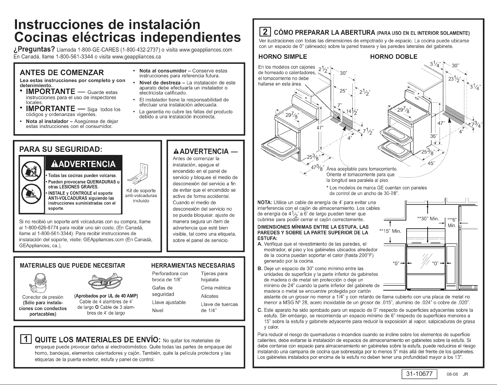
I'_ COMO PREPARAR LA ABERTURA (PARA USO EN EL INTERIOR SOLAMENTE)
Ver ilustraciones con todas las dimensiones de empotrado y de espacio. La codna puede ubicarse
con un espacio de 0" (alineado) sobre la pared trasera y las paredes laterales del gabinete.
HORNO SIMPLE HORNO DOBLE
En los modelos con cajones
de horneado o calentadores,
el tomacorriente no debe
hallarse en esta Area.
\_'_47_/8 '' Area aceptable para tomacorriente. /
"_ Oriente el tomacorriente para que
NOTA: Utilice un cable de energia de 4' para evitar una _ -- I
interferencia con el caj6n de almacenamiento. Los cables
de energia de 41/2' a 6' de largo pueden tener que
cubrirse para poder cerrar el caj6n correctamente. **30" Min.
DIMENSIONES MINIMAS ENTRE LA ESTUFA, LAS 1' -)"
PAREDES Y SOBRE LA PARTE SUPERIOR DE LA *'15" Min.
ESTUFA: ,_
A. Verifique que el revestimiento de las paredes, el
mostrador, el piso y los gabinetes ubicados alrededor
de la cocina puedan soportar el calor (hasta 200°F)
generado por la cocina. *0"-_ _-
B. Deje un espacio de 30" como minimo entre las
unidades de superficie y la parte inferior de gabinetes
de madera o de metal sin protecci6n o deje un
minimo de 24" cuando la parte inferior del gabinete de -- ---
madera o metal se encuentre protegida por cart6n - --
aislante de un grosor no menor a 1/4" y con retardo de llama cubierto con una placa de metal no
menor a MSG NO28, acero inoxidable de un grosor de .015", aluminio de .024" o cobre de .020".
C. Este aparato ha sido aprobado para un espacio de 0" respecto de superficies adyacentes sobre la
estufa. Sin embargo, se recomienda un espacio minimo de 6" respecto de superficies menores a
15" sobre la estufa y gabinete adyacente para reducir la exposici6n al vapor, salpicaduras de grasa
y calor.
Para reducir el riesgo de quemaduras o incendios cuando se incline sobre los elementos de superficie
calientes, debe evitarse lainstalaci6n de espacios de almacenamiento en gabinetes sobre la estufa. Si
debe contarse con espacio para almacenamiento en gabinetes sobre la estufa, puede redudrse el riesgo
instalando una campana de cocina que sobresalga por Io menos 5" mAs aria del frente de los gabinetes.
Los gabinetes instalados por encima de la estufa no deben tener una profundidad mayor a los 13".
30" i
I
L_21/2,,
.... 36" z Z j
la Iongitud sea paralela al piso.
* Los modelos de marca GE cuentan con paneles
de control de un ancho de 30-7/8".
/
/
/J
JL
!
***6" --
Min.
31-10677 ] 08-08 JR
Page 6
I_] REQUERIMIENTOS ELC:CTRICOS
| INSTALACION DE CABLE DE ENERGJA Y DE PASACABLES
Z_ADVERTENCIA: Esta unidad debe contar con una adecuada conexi6n a tierra.
Ai,ADVERTENCIA: Todas las construcciones nuevas, casas rodantes, vehiculos recreativos
e instalaciones donde los c6digos locales no permiten una conexi6n a tierra a trav6s de un neutral
requieren un cable para cocina de 4 conductores aprobado por UL.
ADVERTENClA: Para prevenir un incendio o descarga electrica, no utilice un cable
de extensi6n con este aparato.
Ai,ADVERTENClA: Para prevenir una descarga electrica, quite el fusible o abra el
interruptor de circuitos antes de comenzar la instalaci6n.
Recomendamos que un electricista calificado conecte el cableado el6ctrico y su cocina. Despu6s de la
instalaci6n, solicite al electricista que le indique c6mo desconectar la energia de la cocina.
Usted debe usar un sistema el6ctrico de 60 hercios CA de fase Onicade 120/280 voltios o 120/240
voltios. Si tiene una conexi6n con cableado de aluminio, deben utilizarse conectores adecuadamente
instaladospara utilizar con cableado de aluminio.
Si el servicio el6ctrico provisto no cumple con las especificaciones anteriores, haga que un electricista
con licencia instale un tomacorriente aprobado.
Vigente desde el 1 de enero de 1996, el C6digo EI6ctrico Nacional requiere que las nuevas
construcciones (no existentes) utilicen una conexi6n de cuatro conductores a una cocina el6ctrica.
Cuando instale una cocina el6ctrica en una nueva construcci6n, una casa rodante, un vehiculo
recreativo o un _rea donde los c6digos locales prohiben la conexi6n a tierra a trav6s de un conductor
neutral, consulte la secci6n sobre conexiones en circuito derivado de cuatro conductores.
Consulte alas empresas de servicio pQblico sobre los c6digos el6ctricos que se aplican en su _rea.
No realizar el cableado de su homo de acuerdo con los c6digos vigentes puede provocar una
situaci6n peligrosa. Si no existen c6digos locales, su codna debe contar con cables y fusibles que
cumplan con los requisitos del C6digo EI6ctrico Nacional, ANSI/NFPA No. 70-01tima edici6n.
Este electrodom6stico debe recibir el voltaje y frecuencia adecuados, y debe conectarse a un circuito
derivado individual con adecuada conexi6n a tierra de 40 amperios (minimo) protegido por un
interruptor de circuitos o fusible con retraso.
Utilice s61oun cable para cocinas de 3 o 4 conductores aprobado por UL. Estos cables pueden contar
con terminales de anillo en alambre y un dispositivo de alivio de tensi6n.
Se requiere un cable para cocinas clasificado para 40 amperios con rango de voltios minimo de
125/250. No se recomienda un cable de 50 amperios, pero si se utiliza, debe seNalizarse para usarse
con aberturas de conexi6n de un di_metro nominal de 1-3/8". Debe tenerse cuidado al centrar el cable
y el alivio de tensi6n dentro del orificio de expulsi6n para evitar que el borde dane el cable.
La placa de clasificad6n se encuentra ubicada sobre el caj6n de almacenamiento en el marco del
horno o en el lado del marco del caj6n.
HORNO SIMPLE
HORNO DOBLE
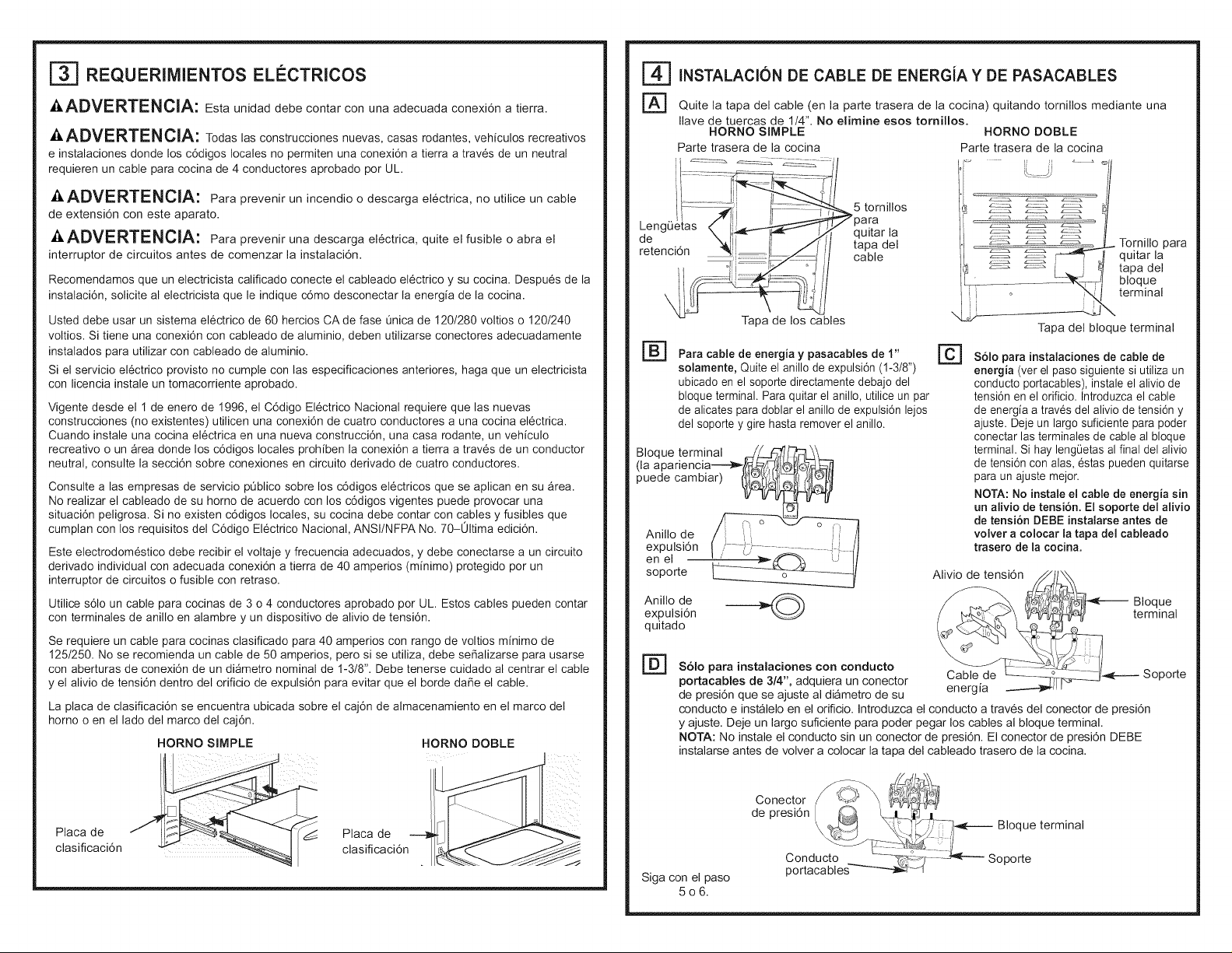
F_ Quite la tapa del cable (en la parte trasera de la cocina) quitando tornillos mediante una
Ilave de tuercas de 1/4". No elirnine esos tornillos.
HORNO SIMPLE HORNO DOBLE
Parte trasera de la cocina Parte trasera de la cocina
_5 tornillos
para
quitar la
tapa del
cable
Tapa de los cables
@
Para cable de energia y pasacables de 1"
solamente, Quite el anillo de expulsi6n (1-3/8")
ubicado en el soporte directamente debajo del
bloque terminal. Para quitar el anillo, utilice un par
de alicates para doblar el anillo de expulsi6n lejos
del soporte y gire hasta remover el anillo.
BIoque terminal
puede cambiar)
Anillo de
expulsi6n
en el
soporte
Anillo de
expulsi6n
quitado
___ _-___-- BelOqUnea,
r_ Solo para instalaciones con conducto
portacables de 3/4", adquiera un conector
de presi6n que se ajuste al di_metro de su
conducto e instalelo en el orificio. Introduzca el conducto a traves del conector de presi6n
y ajuste. Deje un largo suficiente para poder pegar los cables al bloque terminal.
NOTA: No instale el conducto sin un conector de presi6n. El conector de presi6n DEBE
instalarse antes de volver a colocar la tapa del cableado trasero de la cocina.
[]
S61o para instalaciones de cable de
energia (ver el paso siguiente si utiliza un
conducto portacables), instale el alivio de
tensi6n en el orificio. Introduzca el cable
de energia a traves del alivio de tensi6n y
ajuste. Deje un largo suficiente para poder
conectar las terminales de cable al bloque
terminal. Si hay lengOetasal final del alivio
de tensi6n con alas, estas pueden quitarse
para un ajuste mejor.
NOTA: No instale el cable de energia sin
un alivio de tensi6n. El soporte del alivio
de tensi6n DEBE instalarse antes de
volver a colocar latapa del cableado
trasero de la cocina.
Alivio de tensi6n _,,
_. _-_1------ Soporte
Tapa del bloque terminal
Tornillo para
quitar la
tapa del
bloque
terminal
\
Placa de
clasificaci6n
Placa de
clasificaci6n
Siga con el paso
506.
Conector _M @_
de presidn
\ _l:_ \\.t K , _--]_4F---------Bloque terminal
portacableCOnduct°...... _--_':_ Soporte
Page 7
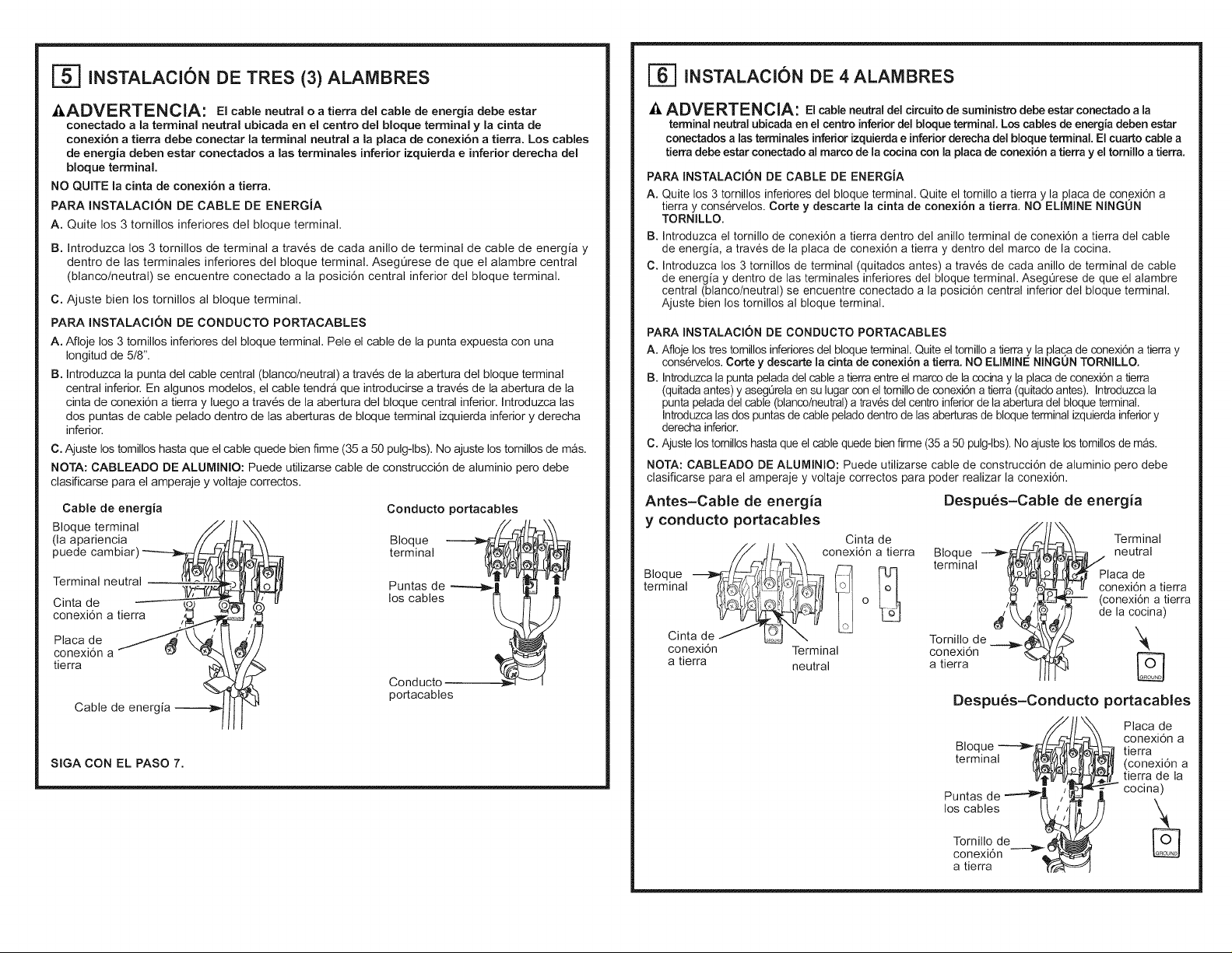
[_ INSTALACI(SN DE TRES (3) ALAMBRES
E_] INSTALAClON DE 4 ALAMBRES
AADVERTENCIA: El cable neutral o a tierra del cable de energia debe ester
conectado a la terminal neutral ubicada en el centro del bloque terminal y la cinta de
cone×i6n a tierra debe conectar la terminal neutral ala place de conexi6n a tierra. Los cables
de energia deben ester conectados alas terminales inferior izquierda e inferior derecha del
bloque terminal.
NO QUITE la cinta de conexi6n a tierra.
PARA INSTALACI(SN DE CABLE DE ENERGIA
A. Quite los 3 tornillos inferiores del bloque terminal.
B. Introduzca los 3 tornillos de terminal a traves de cada anillo de terminal de cable de energia y
dentro de las terminales inferiores del bloque terminal. AsegQrese de que el alambre central
(blanco/neutral) se encuentre conectado ala posici6n central inferior del bloque terminal.
C. Ajuste bien los tornillos al bloque terminal.
PARA INSTALAClON DE CONDUCTO PORTACABLES
A. Afloje los 3 tornillos inferiores del bloque terminal. Pele el cable de la punta expuesta con una
Iongitud de 5/8".
B. Introduzca la punta del cable central (blanco/neutral) a traves de la abertura del bloque terminal
central inferior. En algunos modelos, el cable tendra que introducirse a traves de la abertura de la
cinta de conexi6n a tierra y luego a traves de la abertura del bloque central inferior. Introduzca las
dos puntas de cable pelado dentro de las aberturas de bloque terminal izquierda inferior y derecha
inferior.
C. Ajuste los tomillos haste que el cable quede bien firme (35 a 50 pulg-lbs). No ajuste los tornillos de mas.
NOTA: CABLEADO DE ALUMINIO: Puede utilizarse cable de construcci6n de aluminio pero debe
clasificarse pare el amperaje y voltaje correctos.
Cable de energia
BIoque terminal
(la apariencia
puede cambiar
Terminal neutral
Cinta de
conexi6n a tierra
Place de
conexi6n a
tierra
Cable de energia
SIGA CON EL PASO 7.
Conducto portacables
,oque
terminal
Punta_).de __
Conducto _ _ I
portacables
A ADVERTENCIA: El cable neutral del circuitode suministro debe ester conectado ala
terminal neutral ubicada en el cen_o inferior del bloque terminal. Los cables de energia deben ester
conectados alas terminales inferiorizquierda e inferiorderecha del bloque terminal, El cuarto cable a
tierra debe ester conectado al marco de lacocina con la place de conexion a tierra y el tornillo a tierra.
PAPA INSTALACION DE CABLE DE ENERGJA
A. Quite los 3 tornillos inferiores del bloque terminal. Quite el tornillo a tierra y la place de conexi6n a
tierra y cons6rvelos. Corte y descarte la cinta de conexion a tierra. NO ELIMINE NINGON
TORNILLO.
B. Introduzca el tornillo de conexi6n a tierra dentro del anillo terminal de conexi6n a tierra del cable
de energia, a trav6s de laplaca de conexi6n a tierra y dentro del marco de la cocina.
C. Introduzca los 3 tornillos de terminal (quitados antes) a trav6s de cada anillo de terminal de cable
de energia y dentro de las terminales inferiores del bloque terminal. AsegQrese de que el alambre
central (blanco/neutral) se encuentre conectado ala posici6n central inferior del bloque terminal.
Ajuste bien los tornillos al bloque terminal.
PAPA INSTALACI()N DE CONDUCTO PORTACABLES
A. Afloje los tres tomillos inferiores del bloque terminal. Quite el tornillo a tierray laplace de conexi6n a tierra y
cons6rvelos. Corte y descarte lacinta de conexi6n a tierra. NO ELIMINE NINGUN TORNILLO,
B. Introduzcala puntapelada del cable a tierraentre elmarco de lacocina y la place deconexi6n a tierra
(quitada antes) yasegQrelaensu lugar con eltornillo de conexi6n atierra (quitadoantes). Introduzcala
punta peladadel cable (blanco/neutral)a trav6s del centro inferiorde la abertura del bloque terminal.
Introduzcalas dos puntas de cable pelado dentrode las aberturas de bloqueterminal izquierda inferiory
derecha inferior.
C. Ajuste los tornilloshaste que el cablequede bienfirme (35 a 50 pulg-lbs).Noajuste lostornillosde m_s.
NOTA: CABLEADO DE ALUMINIO: Puede utilizarse cable de construcd6n de aluminio pero debe
clasificarse pare el amperaje y voltaje correctos pare poder realizer la conexi6n.
Antes-Cable de energia Despues-Cable de energia
y conducto portacables
Terminal
//_/LXX conexidnatierra Bloque _
Bloque _.__./_,__f_L___= _ FU_ terminal
terminal _ :.... tolI
Cinta de Tornillo de
conexi6n Terminal conexi6n _'
a tierra neutral a tierra
Cinta de_ _I
Despues-Conducto
Bloque _/_
terminal
Puntas de _ /''_'
_cpo neutral
lace de
nexi6n a tierra
-- (conexi6n a tierra
de la cocina)
)ortacables
Place de
conexi6n a
_ tierra
_ conexidn a
tierra de la
cocina)
los cables _
cT°rnnilxli° de __
a tierra T-r_
Page 8

E_ REEMPLACE LA TAPA DE LOS CABLES
Reemplace la tape de los cables de la cocina deslizando el lade izquierdo bajo las leng(Jetas
de retenci6n y reemplazando los cinco tornillos quitados antedormente. Verifique que los cables
no hayan sufrido pellizcos entre la tape y la parte trasera de la cocina.
CAVlDAD UNICA CAVlDAD DOBLE
Parte trasera de la cocina Parte trasera de la cocina
i......
Leng Q!_'tas_
de retenci6n ",
5 tornillos
)are
quitar la
tape del
cable
Tornillo pare
quitar la
tape del
bloque
terminal
\
Tape de los cables
F_ INSTALACION DE DiSPOSITIVO ANTI-VOLCADURAS
Afin de reducirel riesgode incliner la cocina,6sta deber&
esterasegurada con un soporte antivolcaduras.Lea las
instruccionesde instalaci6nqueseenviaron con el
, L,,_.t_ "Todas las cocinas puedenvolcarse.
-- I" PuedenprovocarseQUEMADURAS
{ _ ) ANTI-VOLCADURASsiguiendo ,as
uotras LESIONESGRAVES.
• INSTALEy CONTROLEel soporte
- instrucciones suministradas con el
_-_ hsopo,te.
pulgadas.De no ser asi, el soporte deber&ser instaladonuevamente.Si la cocina es expulsada de la pared por
alguna raz6n,siemprerepitaeste procedimiento a fin de verificarque est6 aseguradodeforma correcta con un
soporte anti volcaduras.Nunca eliminecompletamentelas pates niveladoras,ya que deser asi la cocina no
ester&adecuadamenteaseguradapor el dispositivoanti volcaduras.
soporte pare obtenerundetalle completo antes de
comenzarla instalaci6n.
Afin decontrolar que el soporteest6 instaladoy adosado
correctamente,retireelcaj6n de almacenajeo la parte
inferior delanteray observedebajo de lacocinaque la
pate niveladoraest6adosadaal soporte. En modelosque
no poseen uncaj6nde almacenajeo parte inferior
delantera, incline con cuidadola cocina haciaadelante. El
soporte deberia detener lacocinadentro de las cuatro
E_ NIVELE LA COCINA
_I.ADVERTENCIA: Nunca quite las pates de nivelaci6n por
completo ya que la cocina noquedara bien sujeta al dispositivo anti-volcaduras.
MODELOS CON CA JONES DE ALMAgENAMIENTO O PANELES
DE PROTEC¢ION
F_ Enchufe la unidad y deslicela en su lugar. Tire del caj6n hacia .... /
fuera haste que pare. l'4wel ae . I1'_ I_
r_ eureuja ae alre i_=_.T_lnl
Levante el frente del caj6n haste que las trabas superen las / _1_
guias. Retire el caj6n. ( __111_
la ubicaci6n donde se va a instalar. _ _llll
_[_ Instale los estantes del homo en el horno y coloque la cocina en _-__L._:;"_IIIH
Controle la nivelaci6n colocando un nivel de burbuja de aire sobre 4_,_
uno de los estantes del homo. Haga dos lectures-con el nivel
ubicado en diagonal primero en una direcci6n y luego en la otra.
F_ Las pates de nivelaci6n frontales pueden ajustarse desde la parte inferior y las pates
traseras pueden ajustarse desde la parte superior o inferior.
r_ Utilice una Ilave ajustable pare ajustar las pates niveladoras haste que la cocina quede
nivelada.
Tape del bloque terminal
F_ NIVELE LA COCINA (CONT.)
@
Coloque el cable de modo que no interfiera con el caj6n.
Coloque el riel del caj6n en las guias. Empuje el caj6n
hacia adentro haste que pare.
Levante el frente del caj6n y empuje haste que las trabas superen
las guias.
Baje el frente del caj6n y empuje hacia adentro haste que cierre.
cocina
MODELOS CON CAJONES DE HORNEADO O CALENTADORES U HORNO DOBLE
FAq
Enchufe la unidad.
@
Mida la altura de su mostrador de encimera en la parte trasera de la aber-
tura (X).
Ajuste las dos pates de nivelaci6n traseras pare que la parte trasera de la
estufa se encuentre ala misma altura del mostrador (Y).
@
Deslice la unidad en su lugar.
@
Instale los estantes del horno en la unidad y coloque la cocina donde se instalar&
F¢q
Controle la nivelaci6n colocando un nivel de burbuja de aire sobre uno de los estantes del
homo. Haga dos lectures-con el nivel ubicado en diagonal primero en una direcci6n y
luego en la otra.
F_ Ajuste las pates de nivelaci6n frontales haste que la cocina quede nivelada.
LISTA DE CONTROL FINAL DE LA
• Verifique que el interruptor de circuitos se encuentre cerrado (RESET) o que los fusibles del circuito
se hayan reemplazado.
• AsegQrese de que se cuente con suministro el6ctrico en el edificio.
• Controle que se haya quitado todo el material de empaque y la cinta. Esto incluye cinta sobre el
panel de metal bajo las perillas de control (si corresponde), cinta adhesiva, ataduras de alambre,
cart6n y pDstico protector. No quitar estos matedales puede provocar daNos al electrodom6stico una
vez que el aparato se haya encendido y las superficies se hayan calentado.
• Controle que la puerta y el caj6n se encuentren paralelos y que los dos funcionen correctamente.
Si no es asi, consulte el Manual del propietado para un reemplazo adecuado.
• Controle que la pata de nivelaci6n trasera est6 bien introducida dentro del soporte anti-volcaduras
y que el soporte se encuentre bien instalado.
INSTALACION
LISTA DE CONTROL DE FUNCIONAMIENTO
• Acdone una de las unidades de superficie pare observer que el elemento se encienda dentro de los
60 segundos. Apague la unidad cuando se detecte el encendido. Si no se detecta el encendido dentro
del limite de tiempo, vuelva a verificar las conexiones del cableado de la cocina. Si se requiere un
cambio, vuelva a prober el aparato. Si no se requiere un cambio, haga controlar el cableado del
edificio pare verificar conexiones y voltaje adecuados.
• Controle que la pantalla del reloj (en modelos que Io incluyan) reciba energia. Si en la pantalla
aparecen una serie de lineas rojas horizontales, desconecte la energia de inmediato. Vuelva a
controlar las conexiones del cableado de la cocina. Si se efectQa un cambio en las conexiones, vuelva
a prober el aparato. Si no se requiere un cambio, haga controlar el cableado del edificio pare verificar
conexiones y voltaje adecuados. Se recomienda cambiar el reloj si aparecen las lineas rojas.
• AsegQrese de que los controles de la cocina se encuentren en la posici6n OFF (apagado) antes de
alejarse de la cocina.
 Loading...