

Page 1
Installation Instructions
Free-Standing Electric Ranges
Questions? Call1.800.GE.CARES(1.800.432.2737)or visit www.GEAppliances.com
InCanada,call 1.800.561.3344or visitwww.GEAppliances.ca
BEFORE YOU BEGIN
Readthese instructions completely and
carefully.
• IM PO RTANT -- Savethese instructions
for local inspector's use.
• IMPORTANT -- Observeall
governing codes and ordinances.
• Note to Installer- Be sure to leave these
instructions with consumer.
FOR YOUR SAFETY:
• A child or adult can tip the range and be killed.
• Install the anti-tip bracket to the wall or floor.
• Engage the range to the anti-tip bracket by sliding the
range back such that the foot is engaged.
• Re-engage the anti-tip bracket if the range is moved.
• Failure to do so can result in death or serious burns
to children or adults.
If you did not receive an anti-tip bracket with your purchase,
call 1.800.626.8774 to receive one at no cost. (InCanada,
call 1.800561.3344.) For installation instructions of the bracket,
visit: www.GEAppliances.com. (InCanada, www.GEAppliances.ca.)
Tip-Over Hazard
MATERIALS YOU MAY NEED
PowerCord Clamp
SqueezeConnector (ULListed40AMP)
(FarConduit 3-Wire Cord4'
Installations Only) long
Strain Relief
• Note to consumer- Keep these
instructions for future reference.
• Skill level -Installation of this appliance
requires a qualified installer or electrician.
• Proper installation is the responsibility of the
installer.
• Product failure due to improper installation is
not covered under warranty.
AntPTip Bracket
Kit Included
_i, WARN ING Before beginning the
installation, switch power off at service
panel and lockthe service disconnecting
means to prevent power from being
switched on accidentally. When the
service disconnecting means cannot
belocked, securely fasten a prominent
warning device, such as a tag, to the
service panel.
TOOLS YOU WILL NEED
Drill with 1/8" Bit Tin Snips
Safety Glasses Tape Measure
Adjustable Wrench Pliers
Level 1/4" Nut Driver
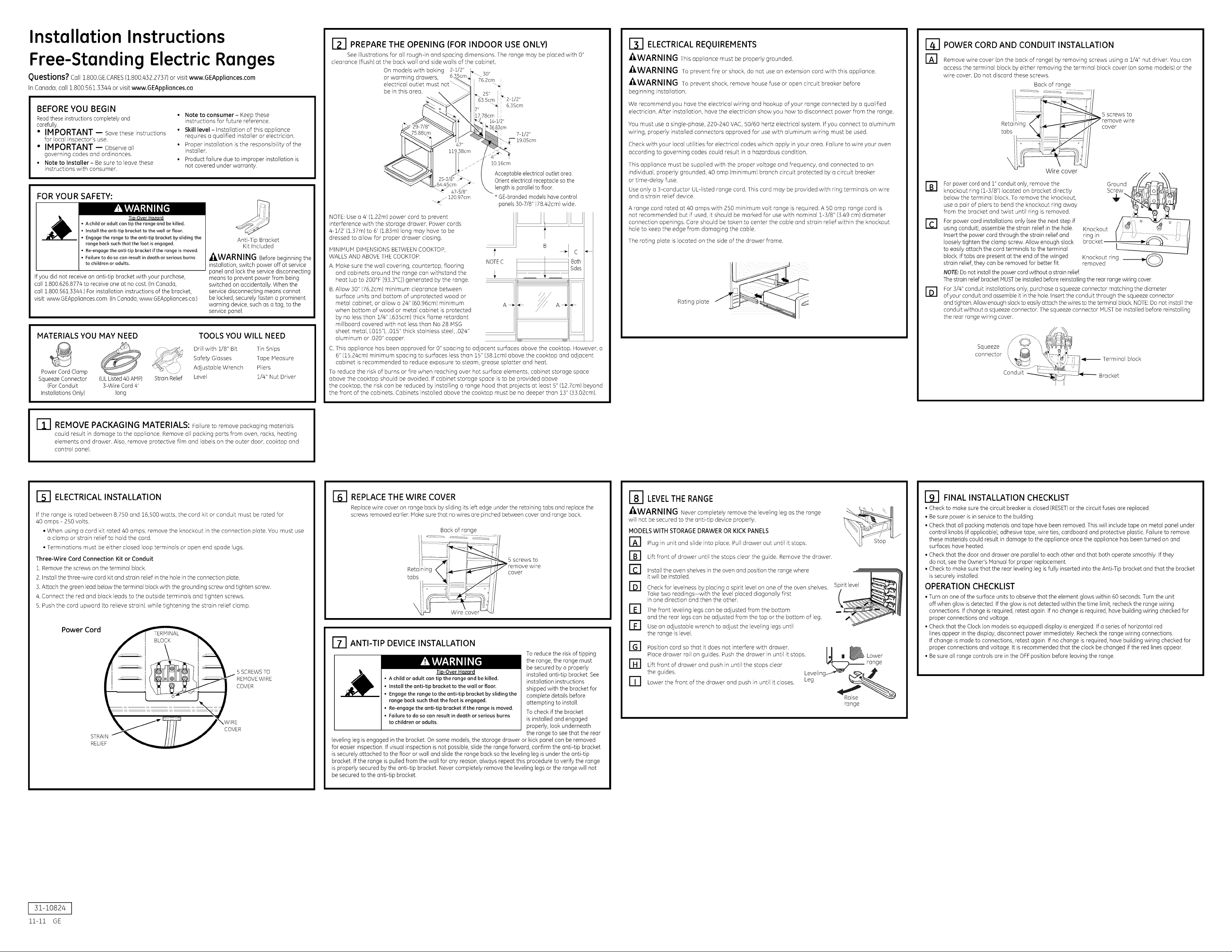
_-I PREPARE THE OPENING (FOR INDOOR USE ONLY}
See illustrations for all rough-in and spacing dimensions. The range may be placed with 0"
clearance (flush) at the back wall and side walls of the cabinet.
On models with baking 2-1/2"
or warming drawers, 76.2cm
electrical outlet must "_
be in this area. ::
NOTE:Use a a' (1.22m) power cord to prevent
interference with the storage drawer. Power cords
4-1/2' (1.37m)to 6' (1.83m) long may have to be
dressed to allow for proper drawer closing.
MINIMUM DIMENSIONS BETWEEN COOKTOP,
WALLS AND ABOVE THE COOKTOP:
A. Make sure the wall covering, countertop, flooring
and cabinets around the range can withstand the
heat (upto 200°F [93.3°C])generated by the range.
B.Allow 30" (76.2cm) minimum clearance between
surface units and bottom of unprotected wood or
metal cabinet, or allow a 24" (60.96cm) minimum
when bottom of wood or metal cabinet is protected
by no less than 1/4" (.635cm) thick flame retardant
millboard covered with not less than No 28 MSG
sheet metal, (.015'1, .015" thick stainless steel, .024"
aluminum or .020" copper. _
C.This appliance has been approved for 0" spacing to adjacent surfaces above the cooktop. However, a
6" (15.24cm) minimum spacing to surfaces less than 15" (38.1cm) above the cooktop and adjacent
cabinet is recommended to reduce exposure to steam, grease splatter and heat.
To reduce the risk of burns orfire when reaching over hot surface elements, cabinet storage space
above the cooktop should be avoided. If cabinet storage space is to be provided above
the cooktop, the risk can be reduced by installing a range hood that projects at least 5" (12.7cm) beyond
the front of the cabinets. Cabinets installed above the cooktop must be no deeper than lY' (33.02cm).
30"
_'2-1/2"
"_ 6.35cm
7"
78cm
14-1/2"
lO.16cm
Acceptableelectricaloutlet area.
Orientelectrical receptacle sothe
length is parallelto floor.
* GE-brandedmodelshavecontrol
panels30-7/8" (78.42cm) wide.
t
NOTEC
A_ _- A_
Both
c
Sides
i
ELECTRICAL REQUIREMENTS
-&WARNING This appliance must be properly grounded.
-&WARNING To prevent fire or shock, do not use an extension cord with this appliance.
-&WARN ING To prevent shock, remove house fuse or open circuit breaker before
beginning installation.
We recommend you have the electrical wiring and hookup of your range connected by a qualified
electrician. After installation, have the electrician show you how to disconnect power from the range.
You must use a single-phase, 220-240 VAC, 50/60 hertz electrical system. If you connect to aluminum
wiring, properly installed connectors approved for use with aluminum wiring must be used.
Check with your local utilities for electrical codes which apply in your area. Failure to wire your oven
according to governing codes could result in a hazardous condition.
This appliance must be supplied with the proper voltage and frequency, and connected to an
individual, properly grounded, 40 amp (minimum) branch circuit protected by a circuit breaker
or time-delay fuse.
Use only a 3-conductor UL-listed range cord. This cord may be provided with ring terminals on wire
and a strain relief device.
A range cord rated at 40 amps with 250 minimum volt range is required. A 50 amp range cord is
not recommended but if used, it should be marked for use with nominal 1-3/8" (3.49 cm) diameter
connection openings. Care should be taken to center the cable and strain relief within the knockout
hole to keep the edge from damaging the cable.
The rating plate is located on the side of the drawer frame.
Rating plate
POWER CORD AND CONDUIT INSTALLATION
r_ Remove wire cover (on the back of range) by removing screws using a 1/4" nut driver. You can
access the terminal block by either removing the terminal block cover (on some models) or the
wire cover. Donot discard these screws.
Back of range
wire
cover
Wire cover
rB1 Forpowercordand 1" conduit only, remove the
knockout ring (1-3/8")located on bracket directly
below the terminal block. To remove the knockout,
use a pair of pliers to bend the knockout ring away
from the bracket and twist until ring is removed.
rCl For power cord installations only (seethe nextstep if
using conduit), assemble the strain relief in the hole.
Insert the powercord through the strain relief and
loosely tighten the clamp screw. Allow enough slack
to easily attach the cord terminals to the terminal
block. Iftabs are present at the end of the winged
strain relief, they can be removed for better fit.
NOTE:Donat install the power cordwithout a strain relief.
The strain reliefbracket HUSTbeinstalled before reinstallingthe rear rangewiring cover.
For 3/4" conduit installations only, purchase a squeeze connector matching the diameter
B1
ofyour conduit and assemble it in the hole.Insert the conduit through the squeeze connector
and tighten.Allow enoughslack to easily attach the wires to the terminal block. NOTE:Donot install the
conduit without a squeeze connector. Thesqueeze connector MUSTbe installed before reinstalling
the rear range wiring cover.
Squeeze
connector
_9, ;_'_- Terminal
L.onaul_ ___._._ Bracket
"_. t, ,_- block
rmgm I /' :'/ _ /' II
bracket !/ _--_",_'_ b' II
Knockout ring ___
removed
..............7o:A
REMOVE PACKAGI NG MATERIALS: Failure to remove packaging materials
could result in damage to the appliance. Remove all packing parts from oven, racks, heating
elements and drawer. Also, remove protective film and labels on the outer door, cooktop and
control panel.
ELECTRICAL INSTALLATION
If the range is rated between 8,750 and 16,500 watts, the cord kit or conduit must be rated for
40 amps - 250 volts.
• When using a cord kit rated 40 amps, remove the knockout in the connection plate. You must use
a clamp or strain relief to hold the cord.
• Terminations must be either closed loop terminals or open end spade lugs.
Three-Wire Cord Connection Kit or Conduit
1.Remove the screws on the terminal block.
2. Install the three-wire cord kit and strain relief inthe hole in the connection plate.
3. Attach the green lead below the terminal block with the grounding screw and tighten screw.
4. Connect the red and black leads to the outside terminals and tighten screws.
5. Push the cord upward (to relieve strain), while tightening the strain relief clamp.
Power Cord
5 SCREWS TO
REMOVE WIRE
COVER
WIRE
COVER
STRAIN
RELIEF
REPLACE THE WIRE COVER
Replacewire cover on range back bysliding its ]eft edge under the retaining tabs and replace the
screws removed earlier.Make sure that no wires are pinched between cover and range back.
Back of range
5 screws to
cover
[_ ANTI-TIP DEVICE INSTALLATION
To reduce the risk of tipping
the range, the range must
• Achild or adult can tip the range and be killed.
Tip-Over Hazard
• Install the anti-tip bracket to the wall or floor.
• Engage the range to the anti-tip bracket by sliding the
range back such that the foot is engaged.
• Re-engage the anti-tip bracket if the range is moved.
• Failure to do so can result in death or serious burns
to children or adults.
leveling legis engaged in the bracket. On some models,the storage drawer or kick panel can be removed
for easier inspection. If visual inspection is not possible,slide the range forward, confirm the anti-tip bracket
is securely attached to the floor or wall and slide the range back so the leveling leg isunder the anti-tip
bracket. If the range is pulled from the wall for any reason, always repeat this procedure to verify the range
is properly secured by the anti-tip bracket. Never completely remove the leveling legs or the range will not
be secured to the anti-tip bracket.
be secured by a properly
installed anti-tip bracket. See
installation instructions
shipped with the bracket for
complete details before
attempting to install.
To check if the bracket
is installed and engaged
properly, look underneath
the range to see that the rear
rsl LEVEL THE RANGE
_WARNI NG Never completely remove the leveling leg as the range
will not besecured to the anti-tip device properly.
MODELS WITH STORAGE DRAWER OR KICK PANELS
r_ Plug in unit and slide into place. Pull drawer out until it stops.
Lift front of drawer until the stops clear the guide. Remove the drawer.
E1
Install the oven shelves in the oven and position the range where
it will be installed.
B1
Check for levelness by placing a spirit level on one of the oven shelves. Spirit level
Taketwo readings-with the level placed diagonally first
in one direction and then the other.
r_ The front leveling ]egs can be adjusted from the bottom
and the rear legs can be adjusted from the top or the bottom of leg.
El Use an adjustable wrench to adjust the leveling legs until
the range is level.
Position cord so that it does not interfere with drawer. /_.
Place drawer rail on guides. Push the drawer in until it stops. _l._ Lower
rill Lift front of drawer and push in until the stops clear ,,_. _ range
the guides. LeveFng---'_ K_'_ _1_
ITI Lower the front of the drawer and push in until it closes, g
"_ _\ "' >K Ill
Raise
range
191 FINAL INSTALLATION CHECKLIST
• Check to make sure the circuit breaker isclosed (RESET)or the circuit fuses are replaced.
• Be sure power is inservice to the building.
• Check that all packing materials and tape have been removed. Thiswill include tape on metal panel under
control knobs (ifapplicable), adhesive tape, wire ties,cardboard and protective plastic. Failure to remove
these materials could result in damage to the appliance once the appliance has been turned on and
surfaces have heated.
• Check that the door and drawer are parallel to each other and that both operate smoothly. If they
do not,see the Owner's Manual for proper replacement.
• Check to make sure that the rear leveling leg isfully inserted into the Anti-Tip bracket and that the bracket
is securely installed.
OPERATION CHECKLIST
• Turn on one of the surface units to observe that the element glows within 60 seconds.Turn the unit
off when glow isdetected. Ifthe glow is not detected within the time limit, recheck the range wiring
connections. If change is required, retest again. Ifno change is required, have building wiring checked far
proper connections and voltage.
• Check that the Clock(on models so equipped) display is energized. If a series of horizontal red
lines appear in the display, disconnect power immediately. Recheck the range wiring connections.
Ifchange is made to connections, retest again. If no change is required, have building wiring checked for
proper connections and voltage. It is recommended that the clock be changed if the red lines appear.
• Be sure all range controls are in the OFFposition before leaving the range.
31-10824
11-11 GE
 Loading...