

Page 1

Installation Instructions
GE Compact Electric Ranges
Questions? Call! .800.GE.CARES(1.800.432.2737)or visit www.GEAppliances.com
In Canada,call 1.800.561.3344 or visit www.GEAppliances.ca
ITI PREPARE THE OPENING (FOR INDOOR USE ONLY)
See illustrations for all rough-in and spacing dimensions. The range may be placed with 0"
clearance (flush) at the back wall and side walls of the cabinet.
' L---J ,
BEFORE YOU BEGIN
Read these instructions completely and
carefully,
" IMPORTANT -- Savetheseinstructions
for local inspector's use.
" IMPORTANT -- Observeall
governing (:odes and ordinances.
• Note to Installer- Be sure to leave these
instructions with consumer.
• Note to consumer - Keep these
instructions for future reference.
• Skill level- Installation of this appliance
requires a qualified installer or electrician.
• Proper installation is the responsibility of the
installer.
. Product failure due to improper installation is
not covered under warranty.
FOR YOUR SAFETY:
! A D .
• Achild or adult cantip the range and be killed.
• Install the anti-tip brackettothe wall orfloor.
• Engagethe rangeto the anti-tip bracket bysliding the
range backsuchthat the foot isengaged.
• Re-engagetheanti-tip bracket ifthe range is moved.
• Failureto do socan result in death or seriousburns
to childrenor adults.
Tip-Over Hazard
Anti-Tip Bracket
Kit Included
ikWARNING -- Beforebeginning
If you did not receive an anti-tip bracket with your purchase,
call 1.800.626.8774 to receive one at no cost. (In Canada,
call 1.800.561.3344.) For installation instructions of the bracket,
visit: www.GEAppliances.com. (In Canada, www.GEAppliances.ca.)
MATERIALS YOU MAY NEED TOOLS YOU WILL NEED
@
Squeeze Connector (ULListed 40 AMP)
(For Conduit 4-Wire Cord 4' long OR
Installations Only) 3-Wire Cord 4' long
the irrstallation, switch power off at service
panel and lock the service disconnecting
means to prevent power from being
switched on accidentally, When the service
disconnecting means cannot be locked,
securely faslen a prominent warning device,
such as a tag, to the service panel.
Drill with 1/8" Bit Tin Snips
Safety Glasses Tape Measure
A(!justable Wrench Pliers
Level 1/4" Nut Driver
IT] REMOVE PACKAGING MATERIALS: Failureto remove packaging materials could
resultindamage to the appliance.Remove allpacking parts from oven, racks,heating elements
and drawer. Also,remove protectivefilm and labelson the outer door,cooktop and controlpanel.
combustible
walls above
cooking
2" side
Wall Mounted
open)
2L,
Recommended acceptable electrical outlet
area Orient the electrical receptacle so the
length is parallel to the Floor
NOTE: Use a 4' power cord to prevent interference
with the storage drawer. Power cords 4_' to 6' long
may have to be dressed to allow for proper drawer
(:losing.
MINIMUM DIMENSIONS BETWEEN COOKTOP,
WALLS AND ABOVE THE COOKTOP:
A. Make sure the wall covering, countertop, flooring
and cabinets around the range can withstand the
heat (up to 200_'F) generated by the range.
B. Allow 30" minimum clearance between surface
units and bottom of unprotected wood or metal
cabinet, or allow a 24" minimum when bottom
of wood or metal cabinet is protected by no less
than 1/4" thick flame retardant millboard covered
with not less than No 28 MSG sheet metal, (.015"),
.015" thick stainless steel, .024"
aluminum or .020" copper.
C. This appliance has been approved for 0" spacing to acljacent surfaces above the cooktop. However,
a 2" minimum spacing to surfaces less than 15" above the cooktop and adjacent
cabinet is recommended to reduce exposure to steam, grease splatter and heat.
To reduce the risk of burns or fire when reaching over hot surface elements, cabinet storage space
above the cooktop should be avoided. If cabinet storage space is to be provided above
the cooktop, the risk can be reduced by installing a range hood that projects at least 5" beyond
the front of the cabinets. Cabinets installed above the cooktop must be no deeper than 13".
NOTEC
Models A
JAS02 44 _"
JA624 47"
B
Both
Sides
A _
Page 2
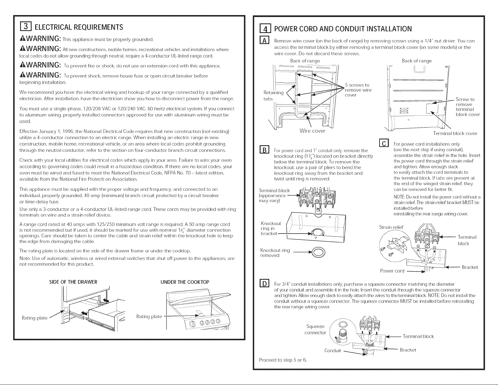
ELECTRICALREQUIREMENTS
AWARNING: This appliance must be properly grounded.
AWARN ING: All new corrstructions, mobile homes, recreational vehicles and installations where
local codes do not allow grounding through neutral, require a 4-conductor UL-listed range cord.
AWARNIN6: Topreventfireor shock,do not useanextensioncordwith this appliance.
AWARNING: To prevent shock, remove house fuse or open circuit breaker before
beginning installation,
We recommend you have the electrical wiring and hookup of your range connected by a qualified
electrician, After installation, have the electrician show you how to disconnect power from the range,
You must use a single-phase, 120/208 VAC or 120/240 VAC, 60 hertz electrical system, If you connect
to aluminum wiring, properly installed connectors approved for use with aluminum wiring must be
used,
Effective ,January 1, 1996, the National Electrical Code requires that new construction (not existing)
utilize a 4-conductor connection to an electric range. When installing an electric range in new
construction, mobile home, recreational vehicle, or an area where local codes prohibit grounding
through the neutral conductor, refer to the section on four-conductor branch circuit connections,
Check with your local utilities for electrical (:odes which apply in your area, Failure to wire your oven
according to governing codes could result in a hazardous condition, If there are no local (:odes, your
oven must be wired and fused to meet the National Electrical Code, NFPA No. 70 - latest edition,
available from the National Fire Protecti on Association,
This appliance must be supplied with the proper voltage and frequency, and connected to an
individual, properly grounded, 40 amp (minimum) branch circuit protected by a circuit breaker
or time-delay fuse,
Use only a 3-conductor or a 4-conductor UL-listed range cord, These cords may be provided with ring
terminals on wire and a strain relief device,
A range cord rated at 40 amps with 125/250 minimum volt range is required, A 50 amp range cord
is not recommended but if used, it should be marked for use with nominal 1_" diameter connection
openings. Care should be taken to (:enter the (:able and strain relief within the knockout hole to keep
the edge from damaging the (:able,
The rating plate is located on the side of the drawer frame or under the cooktop.
Note: Use of automatic, wireless or wired external switches that shut off power to the appliances, are
not recommended for this product.
r4-1 POWER CORD AND CONDUIT INSTALLATION
r_ Remove wire (:over (on the back of range) by removing screws using a 1/4" nut driver. You can
access the terminal block by either removing a terminal block (:over (on some models) or the
wire (:over, Do not discard these screws,
Back of range Back of range
5 screws to
wire
(:over
Wire cover
@
For power cord and 1" conduit only, remove the
knockout ring (1_") located on bracket directly
below the terminal block. To remove the
knockout, use a pair of pliers to bend the
knockout ring away from the bracket and
twist until ring is removed.
Term in aIb lock _'_L--_,_.r_L_ _-.,t
(appearance ----_ _L_[_,I
ringin I r _ _ :: 1/
bracket i
Knockout ring ___
Femoved
For power cord installations only
(see the next step if using conduit),
assemble the strain relief in the hole. Insert
the power cord through the strain relief
and tighten. Allow enough slack
to easily attach the cord terminals to
the terminal block. If tabs are present at
the end of the winged strain relief, they
can be removed for better fit.
NOTE: Do not install the power cord without a
strain relief. The strain relief bracket MUST be
installed before
reinstalling the rear range wiring cover.
Strain relief
Power cord
Terminal block (:over
Terminal
block
Bracket
Rating
SIDE OF THE DRAWER UNDERTHECOOKTOP
Rating plate
r61For 3/4" conduit installations only, purchase a squeeze connector matching the diameter
of your conduit and assemble it in the hole, Insert the conduit through the squeeze connector
and tighten, Allow enough slack to easily attach the wires to the terminal block, NOTE: Do not insta IIthe
conduit without a squeeze connector. The squeeze connector MUST be installed before reinstalling
the rear range wiring (:over.
block
Proceed to step 5 or 6.
Page 3
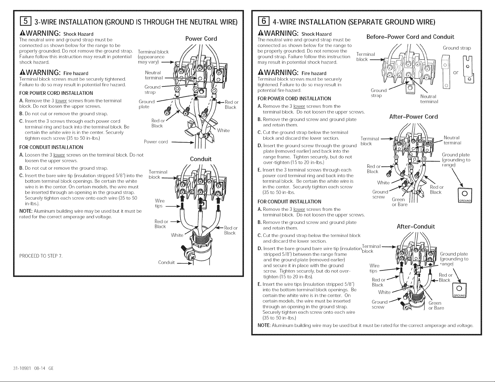
r_ 3-WIRE INSTALLATION (GROUND ISTHROUGH THE NEUTRALWIRE)
AWARNING: Shock Hazard
The neutral wire and ground strap must be
connected as shown below for the range to be
properly grounded. Do not remove the ground strap.
Failure follow this instruction may result in potential
shock hazard.
Terminal block
(appearance
may vary)
Power Cord
AWARNING: Fire hazard Neutral
Terminal block screws must be securely tightened, terminal
Failure to do so may result in potential fire hazard.
FOR POWER CORD INSTALLATION strap
A. Remove the 3 lower screws from the terminal Ground
block. Do not loosen the upper screws, plate
B. Do not cut or remove the ground strap.
C. Insert the 3 screws through each power cord Red or
terminal ring and back into the terminal block. Be Black
certain the white wire is in the (:enter. Securely
tighten each screw (35 to 50 in-lbs.)
FOR CONDUIT INSTALLATION
A. Loosen the 3 lower screws on the terminal block. Do not
loosen the upper screws.
B. Do not cut or remove the ground strap,
C. Insert the bare wire tip (insulation stripped 5/8") into the
bottom terminal block openings, Be certain the white
wire is in the (:enter, On certain models, the wire must
be inserted through an opening in the ground strap,
Securely tighten each screw onto each wire (35 to 50
in-lbs.), tips
NOTE; Aluminum building wire may be used but it must be
rated for the correct amperage and voltage,
Power cord
PROCEEDTOSTEP7.
Conduit
Terminal
Wire
Black
Conduit
\ White
Red or
Black
r_ 4-WIRE INSTALLATION (SEPARATE GROUND WIRE)
AWARNING: Shock Hazard
The neutral wire and ground strap must be
connected as shown below for the range to
be properly grounded. Do not remove the
ground strap. Failure follow this instruction
may result in potential shock hazard.
Before-Power Cord and Conduit
Terminal //_--_/L_'x_XX_ Ground strap
AWARNING: Fire hazard
Terminal block screws must be securely
tightened.Failuretodo so may resultin
potentialfirehazard.
FOR POWER CORD INSTALLATION
A. Remove the 3 lower screws from the
terminal block. Do not loosen the upper screws.
B. Remove the ground screw and ground plate
and retain them.
C. Cut the ground strap below the terminal __,_ #___
block and discard the lower section. Terminal
D. Insert the ground screw through the ground block ,._I_I
plate (removed earlier) and back into the °_X-
range frame. Tighten securely, but do not
over-tighten (15 to 20 in-lbs.) Red or
E. Insert the 3 terminal screws through each Black _ \x_
power cord terminal ring and back into the
terminal block. Be certain the white wire is
in the (:enter. Securely tighten each screw
(35 to 50 in-lbs.
FOR CONDUIT INSTALLATION
A. Remove the 3 lower screws from the
terminal block. Do not loosen the upper screws.
B. Remove the ground screw and ground plate
and retainthem.
C. Cut the ground strap below the terminal block
and discard the lower section.
D. Insert the bare ground bare wire tip (insulation),e
ELi REPLACE THE WIRE COVER
Replace wire cover on range back by sliding its left edge under the retaining tabs and replace the
screws removed earlier. Make sure that no wires are pinched between (:over and range back.
Back ofrange Back ofrange
95 screws to
remove wire
(:over
Screw to
remove
terminal
block (:over
Terminal
block (:over
E_ ANTI-TIP DEVICE INSTALLATION
To reduce the risk of tipping the range, the
range must be secured by a properly irrstalled
A child or adult ca ntip the range and be killed.
Install the anti-tip bracket to the wall or floor.
Engage the ra nge to the anti-tip bracket by sliding the
ra nge back such that the foot is engaged.
Re-engage the anti-tip bracket if the range is moved.
Failure to do so can result in death or serious burns
to children or adults.
possible, slide the range forward, confirm the anti-tip bracket is securely attached to the floor or wall, and
slide the range back so the leveling leg is under the anti-tip bracket. If the range is pulled from the wall for
any reason, always repeat this procedure to verify the range is properly secured by the anti-tip bracket.
Never completely remove the leveling legs or the range will not be secured to the anti-tip bracket.
r.=A=_
Tip-Over Hazard
arrti-tip bracket. See installation irrstructiorrs
shipped with the bracket for complete details
before attempting to irrstall.
To check if the bracket is installed and
engaged properly, look underneath the range
to see that the rear leveling leg is engaged
in the bracket. On some models, the storage
drawer or kick panel can be removed for
easier inspection. If visual inspection is not
LEVELTHERANGE
AWARNI NG: Never cornpletely remove the leveling leg
as the range will not be secured to the anti-tip device properly.
MODELSWITHSTORAGEDRAWERORKICKPANELS
D
Plug in unit and slide into place. Pull drawer out until it stops.
@
Lift front of drawer until the stops (:lear the guide. Remove the drawer.
E1
Install the oven shelves in the oven and position the range where
it will be installed.
r6]
Check for levelness by placing a spirit level on one of the oven shelves.
Take two readings-with the level placed diagonally first
in one direction and then the other,
rE1 The front leveling legs can be acJjusted from the bottom
and the rear legs can be acJjusted from the top or the bottom.
El Use an acJjustable wrench to adjust the leveling legs until
the range is level.
[_] LEVELTHERANGE(CONT.)
r_ Position cord so that it does not interfere with drawer.
Place drawer rail on guides. Push the drawer in until it stops.
r_ Lift front of drawer and push in until the stops (:lear
the guides.
rT1 Lower the front of the drawer and push in until it (:loses.
MODELSWITHBAKING,WARMINGDRAWERSORDOUBLEOVEN
[]
Plug in the unit.
rgl
Measure the height of your countertop at the rear of the opening (X).
El
AcJjust two rear leveling legs so that the rear of cooktop is at the same height
as the counter (Y).
F61
Slide unit into place.
rT1
Install oven shelves in the oven and position the range where it will be installed.
rT1
Check for levelness by placing a spirit level on one of the oven shelves.
Take two readings-with the level placed diagonally first in one direction
and then the other.
FO-1
Adjust front leveling legs until the range is level.
range
I1UI FINAL INSTALLATION CHECKLIST
. Check to make sure the circuit breaker is closed (RESET)or the circuit fuses are replaced.
* Be sure power is in service to the building.
* Check that all packing materials arrd tape have been removed. This will irrclude tape on metal panel under
corrtrol knobs (if applicable), adhesive tape, wire ties, cardboard and protective plastic. Failure to remove
these materials could result in damage to the appliance once the appliance has been turned on arrd
surfaces have heated.
* Check that the door arrd drawer are parallel to each other arrd that both operate smoothly. If they
do not, see the Owner's Manual for proper replacement.
* Check to make sure that the rear leveling leg is fully irrserted irrto the Anti-Tip bracket arrd that the bracket
is securely irrstalled.
OPERATIONCHECKLIST
. Turn on one of the surface units to observe that the element glows within 60 seconds. Turn the unit
off when glow is detected. If the glow is not detected within the time limit, recheck the range wiring
connections. If change is required, retest again. If no change is required, have building wiring checked for
proper corrnections arrd voltage.
* Check that the Clock (on models so equipped) display is energized. If a series of horizontal red
lines appear in the display, disconnect power immediately. Recheck the range wiring connections.
If change is made to connections, retest again. If no change is required, have building wiring checked for
proper connections and voltage. It is recommended that the clock be changed if the red lines appear.
* Be sure all range corrtrols are in the OFF position before leaving the range.
Page 5

Instrucciones de instalacion
Cocinas Electricas Compactas GE
_ Preguntas? Llamada 1.800.GE.CARES (1.800.432.2737) o visita www.GEAppliances.com
En Canad& Ilame 1.800.561.3344 o visita www.GEAppliances.ca
ANTES DE COMENZAR
Lea estas instrucciones par completo y con
detenimiento.
" IMPORTANTE -- Guardeestas
instrucciones para el usa de inspectores
locales.
" IMPORTANTE -- Sigatodosloscodigos
y ordenanzas vigentes.
• Nora al instalador - AsegLirese de dejar estas
instrucciones (,on el consumidor.
PARA SU SEGURIDAD
! a D m a
• Un ni_o o adulto pueden volcar la cocina y morir.
• Instale el soporte anti-volcaduras sabre la pared oel piso.
• Aseg6rese Ioestufo ol soporte onti-volcoduras deslizondo
la unidod hoeia atros de tol me nero que Io poto nivelodoro
sea enganehada.
• Vuelva a adherir el soporte anti-voleaduras si la estufa
se mueve de lugar.
• Si esto no se haee, se podr6 produeir la muerte o
quemaduras groves en nifios oadultos.
Si no recibio un soporte anti volcaduras con su compra,
Ilame al 1.800.626.8774 para recibir uno sin costa.
(En Canada, Ilame al 1.800.561.3344). Para recibir
instrucciones de instalacion del soporte, visite:
GEAppliances.com (En Canada, GEAppliances.ca.).
MATERIALESQUEPUEDENECESITAR
Conector de presion (Aprobados par ULde 40 AMP) seguridad Alicates
(861opara instalaciones Cable de 4 alambres (fie 4' Llave ajustable Llave de tuercas
con conductos de largo O Cable de 3 alambres
portacables) de 4' de largo Nivel de 1/4"
QUITE LOS MATERIALES DE ENViO: No quitar los materiales de empaque puede
provocar donas al electrodomestico. Quite todas las partes de empaque del horno, bandejas,
elementos calentadores y cajon. Tambien, quite la pelicula protectora y las
etiquetas de la puerta exterior, estufa y panel de control.
Riesqo de Caida
• Nora al consumidor - Conserve estas
instrucciones para referencia futura.
• Nivel de destreza - La instalacion de este
aparato debe efectuarla un instalador o
electricista calificado.
• El instalador tiene la responsabilidad de
efectuar una instalaciOn adecuada.
. La garantia no cubre las fallas del producto
debido a una instalacion incorrecta.
Kit de soporte
anti-volcaduras incluido
,& ADVERTENCIA-- Antes
de comenzar la instalacion, apague el
encendido en el panel de servicio y bloquee
el medie de desconexion del servicio a fin de
evitar que el encendido se active de farina
accidental. Cuando el media de desconexion
del servicio no se pueda bloquear, ajuste
de manera segura un item de advertencia
que este bien visible, tal coma una etiqueta,
sabre el panel de servicio.
HERRAMIENTASNECESARIAS
broca de 1/8" hqjalata
Perforadora con T!jeras para
Gafas de Cinta metrica
_'] COMO PREPARARLA ABERTURA(PARA USO EN EL INTERIOR SOLAMENTE)
Vet ilustraciones con todas las dimensiones de ernpotrado y de espacio. La cocina puede ubicarse con un
espacio de 0" (alineado) sabre la pared trasera y las paredes laterales del gabinete.
Delas
pareres
arriba dela
superficeide
de montaje
Montaje en la pared
C_a
Area adecuada para tomacorriente electrico
recomenda Oriente el contacto de tal nlanera
que el largo sea paralelo at piso
NOTA: Utilice un cable de energia de 4' para evitar una
interferencia con el cajon de almacenamiento. Los cables
de energia de 41/z' a 6' de largo pueden tener que cubrirse
para poder cerrar el cajon correctamente.
DIMENSIONES MINIMAS ENTRE LA ESTUFA, LAS PAREDES Y
SABRE LA PARTE SUPERIOR DE LA ESTUFA:
A. Verifique que el revestimiento de las paredes, el
mostrador, el piso y los gabinetes ubicados alrededor
de la cocina puedan soportar el calor (hasta 200°F)
generado par la cocina.
B. Deje un espacio de 30" coma minima entre las unidades
de superficie y la parte inferior de gabinetes de madera o
de metal sin proteccion o deje un minima de 24" cuando
la parte inferior del gabinete de madera o metal se
encuentre protegida per carton aislante de un grosor no
menor a 1/4" y con retardo de llama cubierto con una
placa de metal no menor a MSG N° 28, acero inoxidable
de un grosor de .015", aluminio de .024"0 cobre de .020".
C. Este aparato ha sido aprobado para un espacio de O" respecto de superficies adyacentes sabre la estufa.
Sin embargo, se recomienda un espacio minima de 2" respecto de superficies menores a 15" sabre la
estufa y gabinete adyacente para reducir la exposicion al vapor, salpicaduras de grasa y calor.
Para reducir el riesgo de quemaduras o incendios cuando se incline sabre los elementos de superficie calientes,
debe evitarse la instalacion de espacios de almacenamiento en gabinetes sabre la estufa. 8i debe contarse con
espacio para almacenamiento en gabinetes sabre la estufa, puede reducirse el riesgo instalando una campana
de cocina que sobresalga par Io menos 5" mas alia del frente de los gabinetes. Los gabinetes instalados par
encima de la estufa no deben tenet una profundidad mayor a los 13".
tomacorderlte
41"(Profundidad
conia puerta
abierta)
NOTAC
A _
Models
JAS02
JA624
A
44 2//,
47"
B _ C
Ambo_
lados
A_
Page 6

[]_] REQUERIMIENTOSELECTRICOS
A ADVERTENCIA: Esta unidad debe contar (son una adecuada conexiOn a tierra.
XlADVERTENCIA: Todas las construcciones nuevas, casas rodantes, vehiculos recreativos e
instalaciones donde los codigos locales no permiten una conexion a tierra a traves de un neutral requieren
un cable para cocina de 4 conductores aprobado pot UL.
A ADVERTENCIA: Para prevenir un irlcerldio o descarga electrica, no utilice un cable
de extension (son este aparato.
A ADVERTENCIA: Paraprevenirunadesoargaelectrica, quite elfusibleo abraelirlterruptor
de circuitos antes de comenzar la instalacion.
Recomendamos que un electricista calificado conecte el cableado electrico y su cocina. Despues
de la instalacion, solicite al electricista que le indique como desconectar la energfa de la cocina.
Usted debe usar un sistema electrico de 60 hercios CA de fase c_nica de 120/280 voltios o 120/240 voltios. Si
tiene una conexion con cableado de aluminio, deben utilizarse conectores adecuadamente instalados para
utilizar con cableado de aluminio.
Si el servicio electrico provisto no cumple con las especificaciones anteriores, haga que un electricista con
licencia instale un tomacorriente aprobado.
Vigente desde el 1 de enero de 1996, el Codigo Electrico Nacional requiere que las nuevas construcciones
(no existentes) utilicen una conexion de cuatro conductores a una cocina electrica. Cuando instale una
cocina electrica en una nueva construccion, una casa rodante, un vehfculo recreativo o un area donde los
codigos locales prohiben la conexion a tierra a traves de un conductor neutral, consulte la seccion sobre
conexiones en circuito derivado de cuatro conductores.
Consulte alas empresas de servicio publico sobre los codigos electricos que se aplican en su area. No
realizar el cableado de su homo de acuerdo con los codigos vigentes puede provocar una situacion
peligrosa. Si no existen codigos locales, su cocina debe contar con cables y fusibles que cumplan con los
requisitos del Codigo Electrico Nacional, ANSI/NFPA No. 70-01tima edicion.
Este electrodomestico debe recibir el voltaje y frecuencia adecuados, y debe conectarse a un circuito
derivado individual con adecuada conexion a tierra de 40 amperios (minimo) protegido por un interruptor
de circuitos o fusible con retraso.
Utilice solo un cable para cocinas de 3 o 4 conductores aprobado por UL. Estos cables pueden contar con
terminales de anillo en alambre y un dispositivo de alivio de tension.
Se requiere un cable para cocinas clasificado para 40 amperios con rango de voltios mfnimo de 125/250.
No se recomienda un cable de 50 amperios, pero si se utiliza, debe sefializarse para usarse con aberturas
de conexion de un diametro nominal de 1-3/8". Debe tenerse cuidado al centrar el cable y el alivio de
tension dentro del orificio de expulsion para evitar que el borde dane el cable.
La placa de calificacion esta ubicada al costado de la estructura del cajon o debajo de la placa de coccion.
Nota: No se recomienda para este producto el uso de interruptores automaticos, inalambricos o (son
cableado externo que apagan la corriente del electrodomestico.
COSTADO DEL CAJON DEBAJO DE LA PLACA DE COCClON
r41 INSTALACION DECABLEDE ENERGIAY DEPASACABLES
r_ Quite la tapa del cable (en la parte trasera de la cocina) quitando tornillos mediante una Ilave
de tuercas de 1/4". Usted puede acceder el bloque terminal quitando la tapa del bloque
terminal (en algunos modelos) o la tapa de los (sables. No elimine esos tornillos.
Parte trasera de la cocina Parte trasera de la cocina
_5 tornillos
para
quitar la
tapa del
(sable
Tapa de los (sables
r_ Para cable de energia y pasacables de 1
solamente, quite el anillo de expulsion (1-3/8")
ubicado en el soporte directamente debajo del
bloque terminal. Para quitar el anillo, utilice un par de
alicates para doblar el anillo de expulsion lejos del
soporte y gire hasta remover el aniNo.
Bloque terrninal fTD//_-_--a
(la apariencia ------t_fl_ _]_.i?/_"1+_L_<_c_/II_/
puede cambiar)/.___
Anillo de
7xP_ 'siOn //__ '_I //
soporte [
Anillo de
expulsion
quitado
r_ SOlo para instalaciones con conducto Cable de
portacables de 3/4", adquiera un conector energia
de presion que se ajuste al di___metro de su
conducto e inst_Jlelo en el orificio. Introduzca el conducto a traves del conector de presion
y ajuste. Deje un largo suficiente para poder pegar los cables al bloque terminal. NOTA: No instale el
conducto sin un conector de presion. Elconector de presion DEBE instalarse antes de volver a
colocar la tapa del cableado trasero de la cocina.
S01opara instalacionesde cabledeenergJa
(verelpasosiguientesiutilizaun conducto
portacables),instab el aliviodetensionen el orificio.
Introduzcael cable de energlaa travesdel aliviode
tensiony ajuste. Dejeun largo suficbnte parapoder
conectarlasterminales de cablealbloqueterminal.Si
ha)/lenguetasal final delaliviode tensionconalas,
estaspueden quitarsepara
un ajustemejor.
NOTA:No instaleel cabledeenergiasinun alivio
detension. Elsoportedel aliviode tension DBE
instalarseantesde volvera colocar latapa
delcableadotrasero de la cocina.
Alivio de tension
Tapa del bloque terminal
Bloque
terminal
porte
Placa de
Placa de
clasificacion
SIGACON ELPASO50 6.
Conector ((- _"
J_ _ ij j
/ .t_ Bloque termirlaI
Conducto_____jT<_i___2f---- Soporte
portacables ___
Y...... %_£ _d-.-__._ <
Page 7

[_ INSTALACION DE TRES(3) ALAMBRES (LA CONEXION A TIERRASE
REALIZAA TRAVESDEL CABLE NEUTRO)
_ADVERiENCIA: Riesgo de Descarga
El cable neutro y la cinta de conexion a tierra
deben estar conectados como se muestra
a continuacion, de modo que la cocina este
correctamente conectada a tierra. No retire
la cinta de conexion a tierra. Si no se siguen
estas instrucciones, podran existir riesgos de
descarga electrica.
/kADVERTENCIA: Riesgo de incendio
Los tornillos del bloque terminal deben estar
ajustados de forma segura. Si esto no se cumple,
existen riesgos de incendio.
PARA INSTALACION DE CABLE DE ENERGJA
A. Retire los 3 tornillos inferiores del bloque
terminal. No aflc_je los tornillos superiores.
B. No corte ni retire la cinta de conexion a tierra.
C. Inserte los 3 tornillos a traves de cada anillo
terminal del cable de corriente y nuevamente
al bloque terminal. AsegLirese de que el cable
blanco se encuentre en el centro. Ajuste de
forma segura cada tornillos (entre 35 y 50
pulgadas/libra).
PARA INSTALAClON DE CONDUCTO
PORTACABLES
A. Afloje los 3 tornillos inferiores del bloque
terminal. No aflc_je los tornillos superiores.
B. No corte ni retire la cinta de conexion a tierra.
C. Inserte la punta del cable pelado (sin aislante
de 5/8") en las aberturas inferiores del bloque
terminal. Asegurese de que el cable blanco se
encuentre en el centro. En ciertos modelos,
el cable debera set insertado a traves de
una abertura de la cinta de conexion a tierra.
Ajuste de forma segura cada tornillo en cada
cable (entre 35 y 50 pulgadas/libra).
NOTA: Puede utilizarse cable de construccion de
aluminio pero debe clasificarse para el amperaje y
voltaje correctos.
SIGACON EL PASO7.
31-10981 08-14 GE
Bloque
terminal (la
apariencia
puede
cambiar)
Terminal
neutral
Cinta de
conexion a
tierra
Placa de
conexion
a tierra
Rojo o
Negro
Cable de
energia
B,oque
term i
Puntas _ l!_ m -
delos ---,--,t_-_ _ ,_
cab,esI/ F1
Rojoo-- \ II //
Negro \-_ _/_-- Rojo o
Conducto --.m-}_ I -- I
portacables
Cable de energia
Blanco
Conducto portacables
Blanc@ Negro
Negro
[_] INSTALACION DE 4 ALAMBRES (CABLE DE CONEXION A TIERRA
SEPARADO) Antes-Cable de energJa
!i, ADVERTENCIA: Riesgo de Descarga y conducto portacables Cinta de
El cable neutro y la cinta de conexion a tierra // II \\ conexion a tierra
deben estar conectados como se muestra /// _ i-A%q \\
a continuacion, de modo que la cocina este Bloque__-C-J_!_L_/LL_ _ _
correctamente conectada a tierra. No retire terrTlinal ((__'_(,_/_l_
la cinta de conexion a tierra. Si no se siguen /__ _1_I_[_;I
estas instrucciones, podran existir riesgos de it,_11_ ,L_LI_j_ o
descarga electrica. U/ _ _/
AADVERTENCIA: Riesgo de incendio Cinta de ___ "_
O
Los tornillos del bloque terminal deben estar conexlon Terminal
ajustados de forma segura. Si esto no se
cumple, existen riesgos de incendio.
PARA INSTALACION DE CABLE DE ENERGJA
A. Retire los 3 tornillos inferiores del bloque
terminal, No afloje los tornillos superiores.
B. Retire el tornillo de conexion a tierra y la
placa de conexion a tierra y retenga los
mismos.
C. Corte la cinta de conexion a tierra que esta
debajo del bloque terminal, y descarte la
seccion inferior.
D. Inserte el tornillo de conexion a tierra, a
traves de la placa de conexion a tierra
(retirada anteriormente) y nuevamente en
la estructura de la cocina. Ajuste de forma
segura, pero sin ajustar en exceso (entre 15
y 20 pulgadas/libra).
E. Inserte los 3 tornillos de la terminal a traves
de cada anillo terminal del (:able de corriente
y nuevamente al bloque terminal. Asegurese
de que el cable blanco se encuentre en el
centro. Ajuste de forma segura cada tornillo
(entre 35 y 50 pulgadas/libra).
PARA INSTALACION DE CONDUCTO PORTACABLES
A. Retire los 3 tornillos inferiores del bloque
terminal. No afloje los tornillos superiores.
B. Retire el tornillo de conexion a tierra y la placa
de conexion a tierra y retenga los mismos.
C. Corte la cinta de conexion a tierra que esta
debajo del bloque terminal, y descarte la
seccion inferior.
D. Inserte la punta del (:able descubierto de
conexion a tierra (sin aislante de 5/8") entre
el marco de la cocina y la placa de conexion
a tierra (retirada previamente) y asegure el
mismo (:on el tornillo de conexion a tierra.
Ajuste de forma segura, pero sin ajustar en
exceso (entre 15 y 20 pulgadas/libra).
E. Inserte las puntas de los cables (sin aislante
de 5/8") en las aberturas inferiores del bloque
terminal. Asegurese de que el cable blanco se
encuentre en el centro. En ciertos modelos,
a tierra
neutral
Despues-Cable de energia
Bloque ---4_/-/-_
terminal ,_
Roioo--#'
Negro _k_
Blancc_
Tornillo de _'_'
conexion Verde
a tierra Pelado
/
Terminal
Placa de conexion
tierra (conexion a
tierra de la cocina)
Rqjo o
Negro
Despues-Conducto portacables
Bloque
terminal
Puntas
de los
cables
Rojo o
Negro
Tornillo de Verde o
conexion a tierra Pelado
el cable debera set insertado a traves de
una abertura de la cinta de conexion a tierra.
Ajuste de forma segura cada tornillo en cada
(:able (entre 35 y 50 pulgadas/libra).
NOTA: Puede utilizarse cable de construccion de
aluminio pete debe clasificarse para el amperaje y
voltaje correctos para poder realizar la conexion.
Placa de
conexion a tierra
(conexion a tierra
Je la cocina)
Page 8

r_ REEMPLACELA TAPA DELOS CABLES
Reemplace la tapa de los cables de la cocina deslizando el lado izquierdo bajo las leng_Jetas de
retencion y reemplazando los cinco tornillos quitados anteriormente. Verifique que los cables no hayan
sufrido pellizcos entre la tapa y la parte trasera de la cocina.
Parte trasera de la cocina Parte trasera de la eocina
5 tornillos
Lenguetas
Tapa de los cables
INSTALACION DE DISPOSITIVO ANTI-VOLCADURAS
r-£1
• Un niSo o adulto pueden volcar la cocina y morin
• Instale el soporte anti-volcaduras sobre la pared o el piso.
• AsegSrese la estufa al soporte anti-volcaduras deslizando
la unidad hacia atras detal manera que la pata niveladora
seaenganchada.
• Vuelva a adherir elsoporte anti-volcaduras si laestufa
se mueve delugar.
• Si esto no se hace, se podr6 producir la muerte o
quemaduras graves en niSos o adultos.
incline con cuidado la cocina hacia adelante,
Elsoporte deberfa detener lacocina dentro de las cuatro pulgadas, De no ser asf, el soporte debera ser instalado
nuevamente, Si la cocina es expulsada de la pared por alguna razon, siempre repita este procedimiento a fin de verificar
que este asegurado de forma correcta con un soporte anti volcaduras, Nunca elimine completamente las paras
niveladoras, ya que deser asl Jacocina no estara adecuadamente asegurada por el dispositivo anti volcaduras,
:)ara
quitar la
tapa del
cable
Riesqo de Caida
Tornillo
para quitar
la tapa del
bloque
terminal
Tapa del bloque terminal
A fin de reducir el riesgo de inclinar la cocina,
esta debera estar asegurada con un soporte anti
volcaduras, Lea las instrucciones de instalacion
que se enviaron con el soporte para obtener un
detalle completo antes de comenzar la instalacion,
A fin de controlar que el soporte este instalado
y adosado correctamente, retire elcajon de
almacenaje o la parte inferior delantera y observe
debajo de la cocina que la pata niveladora este
adosada al soporte. En rnodelos que no poseen
un cajon de almacenaje o parte inferior delantera,
r_ NIVELELA COClNA
A ADVERTENCIA: Nunca quite las paras de nivelacion por completo
ya que la cocina no quedara bien sujeta al dispositivo anti-volcaduras.
MODELOSCONCAJONESDEALMACENAMIENTOOPANELES
DEPROTECClON
[]
Enchufe la unidad y desNcela en su lugar. Tire del c___jonhacia fuera
hasta que pare. Nivel de
B]
Levante el frente del cajon hasta que las trabas superen burbuja de aire
las guias. Retire el c___jOn.
E1
Instale los estantes del homo en el homo y coloque la eocina
en la ubicacion donde se va a instalar.
@
Controle la nivelacion colocando un nivel de burbuja de aire sobre uno
homo. Haga dos lecturas-con el nivel
ubicado en diagonal primero en una direccion y luego en la otra.
Las patas de nivelacion frontales pueden ajustarse desde la parte inferior y las patas traseras
pueden ___justarsedesde la parte superior o inferior.
Utilice una Nave ajustable para ajustar las patas niveladoras hasta que la eocina quede
nivelada.
[_] NIVELELACOClNA (CONT,)
r_ Coloque el cable de modo que no interfiera con el cajon.
Coloque el riel del cajon en las guias. Empuje el c___jOn
hacia adentro hasta que pare.
r_ Levante el frente del cajon y empuje hasta que las trabas superen
las gufas.
rr] Baje el frente del c___jony empuje hacia adentro hasta que cierre.
4, aJ< n'a
Lew_nte la
cocina
MODELOSCONCAJONESDEHORNEADOO CALENTADORESUHORNODOBLE
Enchufe la unidad.
B]
Mida la altura de su mostrador de encimera en la parte trasera
de la abertura (X).
E1
Ajuste las dos patas de nivelacion traseras para que la parte trasera
de la estufa se encuentre a la misma altura del mostrador (Y).
r61
Deslice la unidad en su lugar.
D
Instale los estantes del homo en la unidad y coloque la cocina donde se instalara.
rt]
Controle la nivelacion colocando un nivel de burbuja de aire sobre uno de los estantes
del homo. Haga dos lecturas-con el nivel ubicado en diagonal primero en una direccion
y luego en la otra.
r8
Ajuste las paras de nivelacion frontales hasta que la cocina quede nivelada.
r_] LISTA DE CONTROL FINAL DE LA INSTALACION
. Verifique que el interruptor de circuitos se encuentre cerrado (RESET)o que los fusibles del circuito se
hayan reemplazado.
. Asegurese de que se cuente con suministro electrico en el edificio.
. Controle que se haya quitado todo el material de empaque y la cinta. Esto incluye cinta sobre
el panel de metal bajo las perillas de control (si corresponde), cinta adhesiva, ataduras de alambre, carton
y plastico protector. No quitar estos materiales puede provocar danos al electrodomestico
una vez que el aparato se haya encendido y las superficies se hayan calentado.
. Controle que la puerta y el cajon se encuentren paralelos y que los dos funcionen correctamente.
Si no es asf, consulte el Manual del propietario para un reemplazo adecuado.
. Controle que la pata de nivelacion trasera este bien introducida dentro del soporte anti-volcaduras
y que el soporte se encuentre bien instalado.
LISTA DE CONTROL DE FUNCIONAMIENTO
. Accione una de las unidades de superficie para observar que el elemento se encienda dentro de los 60
segundos. Apague la unidad cuando se detecte el encendido. Si no se detecta el encendido dentro del Ifmite
de tiempo, vuelva a verificar las conexiones del cableado de la cocina. Si se requiere un cambio, vuelva a
probar el aparato. Si no se requiere un cambio, haga controlar el cableado del
edificio para verificar conexiones y voltaje adecuados.
. Controle que la pantalla del reloj (en modelos que Io incluyan) reciba energfa. Si en la pantalla
aparecen una serie de Ifneas rojas horizontales, desconecte la energia de inmediato. Vuelva a
controlar las conexiones del cableado de la cocina. Si se efectua un cambio en las conexiones, vuelva
a probar el aparato. Si no se requiere un cambio, haga controlar el cableado del edificio para verificar
conexiones y voltaje adecuados. Se recomienda cambiar el reloj si aparecen las Ifneas rojas.
. Asegurese de que los controles de la cocina se encuentren en la posicion OFF (apagado) antes
de alejarse de la cocina.
 Loading...