

Page 1

GE
Critical Power
Infinity S (NE-S) Dual Voltage Power System
Quick Start Guide
NES4812-23-AC1-PS4-DC1E-LVBD
Read and follow all safety statements and precautions in this guide.
Tools Required:
Cable Crimpers Torque Wrench (0-240 in-lb / 28Nm) 5/16”, 7/16” and ½” nut drivers
Screw Drivers (#1 Flat & #2 Phillips) Wire cutters and strippers
Step 1 - Mount the System
Mount the system with a minimum gap of 3 inches behind the system to allow proper airflow.
1. Attach the system to the frame using a minimum of twelve (six on each side) 12-24 screws (provided).
Torque to 35 in-lb (4 Nm) - 5/16” socket.
Step 2 – Connect Chassis and DC reference (CO) ground
Chassis Ground lug - #10 or 1/4” on 5/8” centers (not provided).
Minimum 10 AWG recommended.
Torque to 10-32 screws to 30 in-lb (3.4 Nm) – 5/16” Socket.
DC reference ground lug - 5/16” or 3/8” on 1” centers (not provided).
Torque to 160 in-lb.
Note: If connecting chassis ground to frame surface remove non-conductive frame coating and apply antioxidant for
connection.
19” /
23”
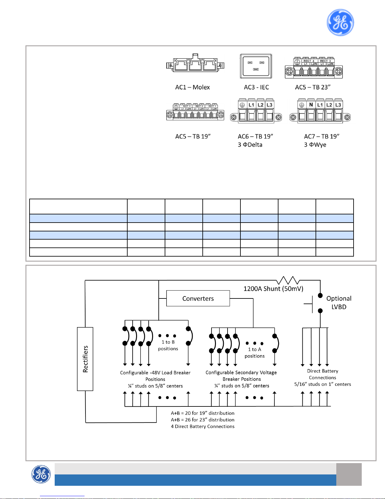
AC Input
AC1 – Molex
AC2 – IEC 320 C19
AC5 – Term Block
AC6 – 3 phase delta Term Block (19” only)
AC7 – 3 phase wye Term Block (19” only)
# of
power
slots
# of
distribution
panels
LVBD
Option
Voltages
48YY
48 – Primary
YY – Secondary
(12 or 24)
Page 2
Infinity S (NE-S) Dual Voltage Power System – Quick Start Guide
2
Document 8600243957P Rev 2 Jan 2019
GE
Critical Power
2
Step 3 – Connect AC inputs
Connect 120/208/220VAC at rear of each
rectifier shelf.
Danger: Turn OFF and lock-out tag-out the AC
source before making AC connections. When
connecting to AC mains, follow all local and
national wiring rules.
Caution: When routing AC ensure cables do
not come in contact with sharp or rough
surfaces that may damage insulation and
cause a short circuit.
Rectifiers numbers are labeled at each AC
input.
AC terminal connections are labeled at each position (L1, L2/N, and Gnd).
AC Terminal Block is in the AC box on the rear of the rectifier shelf
Connect AC input cord to the detachable input terminal block in the wiring box – knock out for ¾” conduit or cord grip.
Strip and torque per the table. Pull on wire to verify secure connection.
AC Input
Rectifiers per
Feed
19”
23”
AWG
max
Strip
Wire (mm)
Torque
In-lb(Nm)
AC1 - Molex mini-fit SR
2 Yes 8 n/a
-
AC3 - IEC-320 C19
1
Yes
Yes
12
n/a
-
AC5 - Terminal Block
1
Yes
Yes
10
10
7 (0.75)
AC6 - Terminal Block 3-phase Delta
3
Yes 6
12
16 (1.75)
AC7 – Terminal Block 3-phase Wye
3
Yes 6
12
16 (1.75)
Step 4 – Connect Batteries and DC Output to Loads
The figure to
the right
shows the DC
circuit of the
system.
Battery
connections
are made
direct to the
battery bus.
Load
Connections
are made
using Load
Breakers in
the main
distribution
area.
Page 3
Infinity S (NE-S) Dual Voltage Power System – Quick Start Guide
3
Document 8600243957P Rev 2 Jan 2019
GE
Critical Power
3
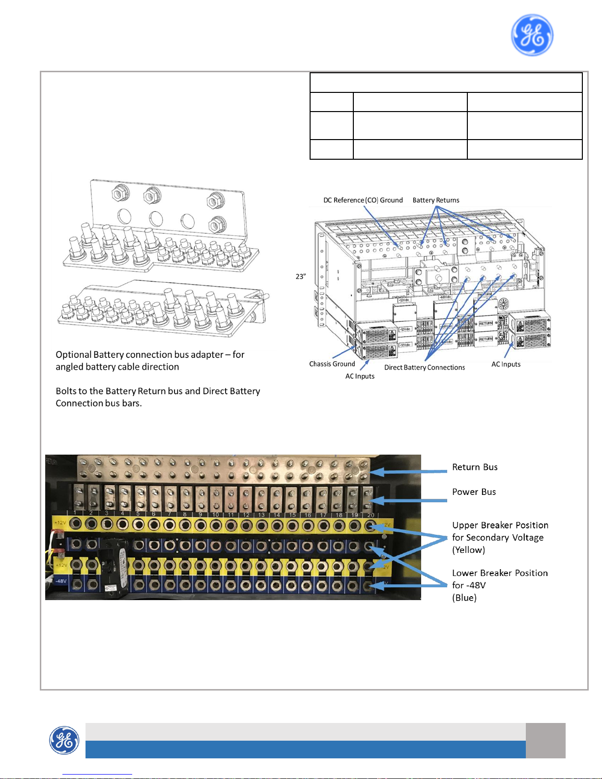
CAUTION: Verify battery voltage and polarity with a
voltmeter before connecting.
Distribution panels are each equipped with 20 (19” panel) or 26 (23” panel) bullet-style distribution positions. Each
position is selectable between Primary or Secondary (Converter) Voltage outputs.
Breaker sizes up to 250A, TPS fuses to 70A and GMT fuses to 12A are available.
Lug Landings
Distribution
Battery Bus
Landings
1/4-20 studs on 5/8” centers
Lug tongue width 0.68” max
5/16-18 studs on 1” centers
Torque
65 in-lb - 7/16” socket
160 in-lb - 1/2” socket
Page 4

Infinity S (NE-S) Dual Voltage Power System – Quick Start Guide
4
Document 8600243957P Rev 2 Jan 2019
GE
Critical Power
4
Two multi-pole adapters required for each
multi-pole breaker – see illustration, right
Multi-Pole Adapter Kits - 2 required per breaker
CC848756916
850021775
850021955
CC848756924
Poles 2 2 3 3
Lug
Landings
1/4” x 5/8”
3/8” x 1”
3/8” x 1”
3/8” x 1”
Step 5 – Set Controller alarm relay jumpers
Pulsar Plus
Set jumpers 1 thru 10 for the ten alarm relays as Close on Alarm or Open on Alarm; Factory default setting is Open on
Alarm.
Page 5

Infinity S (NE-S) Dual Voltage Power System – Quick Start Guide
5
Document 8600243957P Rev 2 Jan 2019
GE
Critical Power
5
Step 6 - Connect Controller Signals
Connect per site engineering instructions.
Pulsar Plus - Connect to J2, J3, J4, and J5.
See Information Controller Connections & Information Battery Connections.
Step 7 –Installation of Power Modules (Rectifier / Converter)
Universal Power Shelves accept rectifier and converters in any slot
Caution: The power unit latch is not a carrying handle.
1. Slide the power unit into the power slot approximately ¾ of the way.
2. Open the faceplate by sliding the latch to the left until the faceplate releases and swings outward.
3. Slide the power unit into the slot until it engages with the back of the shelf. Swing the faceplate closed to fully
seat the unit. Verify the faceplate is latched.
4. Correct insertion of the power unit will automatically add the unit to the controllers’ inventory of units.
To remove a rectifier / converter:
A. Open latch fully to release and remove.
B. Enter Inventory section of controller and remove hardware to clear alarm.
1,
2.
3.
Step 8 – Initial Startup
Verify that all AC, DC and Controller connections are complete and secure. Turn on AC input breakers. If there are no
alarms, make required adjustments to the default settings on the controller for this installation.
Step 9 - Configure Controller
Verify and edit controller basic configuration parameters per site engineering instructions.
Refer to Galaxy Pulsar Plus Product Manual for additional information.
Information: Controller Default Voltage Settings
Parameter
Range
Valve-Reg (Default)
Flooded
NiCd
Rectifier Float Selective High Voltage Shutdown
-50 to -60V
58.50
58.50
58.50
High Float Voltage Major Alarm
-50 to -60V
57.00
57.00
57.00
High Float Voltage Minor Alarm
-50 to -60V
56.00
56.00
56.00
Rectifier/System Float Voltage
-42 to -56.5V
54.48
52.08
54.40
Battery on Discharge Float Alarm
-46 to -55V
51.00
50.00
51.00
Very Low Float Voltage Alarm
-40 to -51V
46.00
46.00
46.00
Rectifier On Threshold
-40 to -51V
44.00
44.00
44.00
Page 6

Infinity S (NE-S) Dual Voltage Power System – Quick Start Guide
6
Document 8600243957P Rev 2 Jan 2019
GE
Critical Power
6
Information: AC Cord Options
IEC-Style, 8ft, 12AWG
Part Number
Plug
Length
CC848847368
No plug
8 ft
CC848850792
5-15P
8 ft
CC848850801
5-20P
8 ft
CC848850826
6-15P
8 ft
CC848850834
6-20P
8 ft
CC848850842
L6-20P
8 ft
850044361
L5-15P
15 ft
850044362
L5-20P
15 ft
CC848895961
L6-20P
15 ft
Molex mini-fit SR-Style, No Plug
CC848822420
(2) 15 ft., 3X8AWG
848710711
(2) 10 ft., 3X8AWG
CC848830522
(2) 4 ft., 3X8AWG
CC848773515
15 ft., 10AWG SO Cord
CC848906586
10 ft., 8AWG, SO Cord
Information: Battery Monitoring Connections
Battery Monitoring is accomplished with a “Daisy Chained” series of probes connected to J2. The Probes monitor battery
temperature and voltage (ES771 required to monitor voltage). Bolt the Probe under the negative terminal connector
hardware; NOT under the connecting lug.
Temperature Measurement Temperature and Voltage Measurement
Information: Battery Monitoring Connections - cables
Temperature Measurement only Temperature and Voltage Measurement
Order Codes
Descriptions
CC109142980
QS873A Thermal Probe
150026698
QS873B Ambient Thermal Probe
CC848817024
B 10’ controller to thermal probe wire set
CC109157434
B 20’ controller to thermal probe wire set
CC848822560
C 1’ thermal probe to thermal probe wire set
848719803
C 5’ thermal probe to thermal probe wire set
CC848822321
C 10’ thermal probe to thermal probe wire set
850027334
C 20’ wire set (thermal probe to thermal probe)
Order Codes
Descriptions
108958422
ES771A Voltage Monitor Card
CC848791517
D 2 ½’ ES771A to probe wire set
CC848797290
D 6’ ES771A to probe wire set
848719829
D 10’ ES771A to probe wire set
CC848791500
G 4’ ES771A to ES771A or controller wire set
848652947
G 10’ ES771A to ES771A or controller wire set
555052-1
In-Line Coupler (for extending item G above)
Page 7

Infinity S (NE-S) Dual Voltage Power System – Quick Start Guide
7
Document 8600243957P Rev 2 Jan 2019
GE
Critical Power
7
Information: Controller Connections
Alarm Outputs
Alarm relays are factory set to Open On
Alarm. If Close On Alarm is desired adjust
controller alarm jumpers. See diagram in
step 5 for the location of the controller alarm
jumpers. Connector J4 provides access to the
primary customer alarm outputs. J4 is a 20pin latching connector.
Alarm Inputs
Default alarm descriptions may be changed as
needed using web pages or Easyview2.
J4 is a 10-pin latching connector.
Standard Controller Alarm Output Defaults
Pin
Color Option 1
Color Option 2
PCR
Power Critical
1
BL
BL
PCR_C
Power Critical C
11 W BL/BK
PMJ
Power Major
2 O O
PMJ_C
Power Major C
12 W O/BK
PMN
Power Minor
3 G G
PMN_C
Power Minor C
13 W G/BK
R1
Battery On Discharge
4
BR
W
R1_C
Battery On Discharge C (BD_C)
14 W W/BK
R2
Very Low Voltage (VLV)
5 S BK
R2_C
Very Low Voltage C (VLV_C)
15 W BK/W
R3
Fuse Alarm Major (FAJ)
6
BL
BL/W
R3_C
Fuse Alarm Major C (FAJ_C)
16 R BL/R
R4
AC Fail (ACF)
7 O O/R
R4_C
AC Fail C (ACF_C)
17 R R
R5
Rectifier Fail (RFA)
8 G G/W
R5_C
Rectifier Fail C (RFA_C)
18 R R/G
R6
Mult. Rectifier Fail (MRFA)
9
BR
W/R
R6_C
Mult. Rectifier Fail C (MRFA_C)
19 R R/W
R7
High Voltage (HV)
10 S BK/R
R7_C
High Voltage C (HV_C)
20 R R/BK
Alarm Output Cables
CC848890137
5 ft.
CC109157442
15ft
CC848817635
50 ft
CC848817643
150 ft
Standard Controller Alarm Input Defaults
J3 Pin
Color
Air Con Fail
1
BK
Air Con Fail Return
8 V Door Open
2
BR
Door Open Return
8 V Aux PMJ Input
3 R Battery Test/GSTR
4
O
Battery Test Return
9 S EPO 5 Y
EPO Return
10 W Hi ext. Temp.
6 G Hi ext. Temp. Return
8 V Low ext. Temp.
7
BL
Low ext. Temp. Return
8
V
Alarm Input Cables
CC848890153
5 ft.
CC848865980
15 ft.
CC848817651
50 ft.
CC848817668
150 ft.
Page 8

Infinity S (NE-S) Dual Voltage Power System – Quick Start Guide
8
Document 8600243957P Rev 2 Jan 2019
GE
Critical Power
8
Information: Controller Basic Operation
View and change system parameters from the factory defaults via
A) Controller Display
B) Craft Port on front of controller using a laptop with EasyView2 software or HyperTerminal.
EasyView2 (GUI) software can be downloaded from www.gecriticalpower.com,
C) J5 LAN port web pages using a laptop with browser. LAN port Server mode is for local laptop connection. Set the LAN
port to Server:
Controller Alarm Status: The display changes colors; Green = Normal, Amber = Minor Alarm, Red = Critical/Major Alarm
Some alarms may occur during initial installation; e.g. thermal probe fail or Major/Minor communication fail .
Clear these alarms: Via Controller Display: follow the menu path;
Menu > Control/Operation > Clear Events or Uninstall Equipment.
Verify Basic Installation Settings: Date, Time, Battery Type, number of strings and float voltage
Menu > Configuration > System Settings and Menu > Configuration > Batteries.
Front Panel
View and change system parameters from the factory defaults via the front panel:
Controller Front Panel Display and Controls
The main menu can be accessed using the Menu / Enter button
The basic menu structure for navigation is shown below:
Front Panel Menu Structure – Overview
Page 9

Infinity S (NE-S) Dual Voltage Power System – Quick Start Guide
9
Document 8600243957P Rev 2 Jan 2019
GE
Critical Power
9
Information – Controller Basic Operation – continued
All user configurable parameters can be accessed from the front panel, however user convenience and visibility is
enhanced by access through the LAN port using the built-in web pages.
Configuration > Communication Ports > Network Settings > DHCP > mode, to SERVER
Once the LAN port is configured as a server, the laptop can be connected to the LAN port, using a standard ethernet
cable. Use a standard web browser to access the controller web pages at default IP address: 192.168.2.1
Warning: Do not connect LAN port to a network when set to Server mode. Set the controller LAN port to Client or Static
before connecting to the network. Static is the factory default setting and the typical setting for most networks.
Once connected to the controller web server a log on screen should be visible:
Logon Screen – web view
Factory Default password is “Administrator” and should be used for initial logon. It is highly recommended that one of
the first activities should be to change the default password(s).
Home Page – Web View
Page 10

Infinity S (NE-S) Dual Voltage Power System – Quick Start Guide
10
Document 8600243957P Rev 2 Jan 2019
GE
Critical Power
10
Information – Rectifiers & Converters
Rectifiers
Order Code
Input
DC Output
Recommended AC Breaker 1Phase
3-Phase
volts
amps
AC1
(2 rects per
feed)
AC3
AC5
AC6
AC7
NE050ECO48ATEZ
150025074
200-400Vac
48V
50A
40A
20A
20A
40A
20A
100-120Vac
48V
22A
40A
20A
20A
60-300Vdc, 11A max
48V
50A
NE075AC48ATEZ
CC109163473
200-277Vac
48V
75/50A1
40A
20A
30A
50A
30A
100-120Vac
48V
25A
40A
20A
20A
NE050AC48ATEZ
CC109158878
208-240Vac
48V
50A
40A
20A
20A
40A
20A
100-120Vac
48V
22A
40A
20A
20A
NE050AC48A
CC109124913
200-240Vac
48V
50A
40A
20A
20A
40A
20A
1 75A with AC5 and AC6, 50A with AC1 and AC3.
Converters
Order Code
Input DC
Output DC
Voltage
Current
Voltage
Current
NE075DC24A
CC109142881
48Vdc
54A Max
24Vdc
75A
NE075DC12AZ
150046488
48Vdc
24A Max
12Vdc
75A
Information: Rectifier Status LEDs
Information: Converter Status LEDs
Specifications and Application
Specifications and ordering information are in the Infinity S Ordering Guide available at www.gecriticalpower.com
External Surge Protective Device (SPD) is required on all AC inputs.
Equipment and subassembly ports:
1. are suitable for connection to intra-building or unexposed wiring or cabling;
2. can be connected to shielded intra-building cabling grounded at both ends.
Grounding / Bonding Network – Connect to an Isolated Ground Plane (Isolated Bonding Network) or an Integrated Ground Plane (Mesh-Bonding
Network or Common Bonding Network).
Installation Environment - Install in Network Telecommunication Facilities, OSP, or where NEC applies.
Battery return may be either Isolated DC return (DC-I) or Common DC return (DC-C).
Reference Documents
These documents are available at www.gecriticalpower.com.
Document Title
CC848815341 Galaxy Pulsar Plus Product Manual
Infinity S Ordering Guide (aka product line brochure)
Page 11

Infinity S (NE-S) Dual Voltage Power System – Quick Start Guide
11
Document 8600243957P Rev 2 Jan 2019
GE
Critical Power
11
Safety Statements
Do not install this equipment over combustible surfaces.
Rules and Regulations - Follow all national and local rules and regulations when making field connections.
Compression Connectors
− U. S. or Canada installations - use Listed/Certified compression connectors to terminate Listed/Certified field-wire conductors.
− All installations - apply the appropriate connector to the correct size conductor as specified by the connector manufacturer,
using only the connector manufacturer’s recommended or approved tooling for that connector.
Electrical Connection Securing: Torque to the values specified on labels or in the product documentation.
Cable Dress - dress to avoid damage to the conductors and undue stress on the connectors.
Circuit Breakers and Fuses
− Use only those specified in the equipment ordering guide.
Size as required by the National Electric Code (NEC) and/or local codes.
Safety Tested Limits - Refer to the equipment ratings to assure current does not exceed
− Continuous Load (List 1) - 60% of protector rating
− Maximum Load (List 2 - typically end of discharge) - 80% of protector rating.
GMT Style Fuses - Use only fuses provided with safety caps.
Field-wired Conductors - Follow all National Electric Code (NEC) and local rules and regulations.
− Insulation rating: 90°C minimum; 105°C (minimum) if internal to enclosed equipment cabinets.
− Size AC field-wired conductors with 75°C ampacity (NEC) equal to or greater than their panel board circuit breaker rating.
AC and DC input disconnect/protection - Provide accessible devices to remove input power in an emergency.
Alarm Signals - Provide external current limiting protection. Rating 60V, 0.5A unless otherwise noted.
Grounding - Connect the equipment chassis directly to ground. In enclosed equipment cabinets connect to the cabinet AC service
ground bus. In huts, vaults, and central offices connect to the system bonding network.
Precautions
Install, service, and operate equipment only by professional, skilled and qualified personnel who have the necessary knowledge and
practical experience with electrical equipment and who understand the hazards that can arise when working on this type of
equipment.
Disconnect batteries from outputs and/or follow safety procedures while working on equipment. Batteries may be connected in
parallel with the output of the rectifiers. Turning off the rectifiers will not necessarily remove power from the bus.
Do not disconnect permanent bonding connections unless all power inputs are disconnected.
Verify that equipment is properly safety earth grounded before connecting power. High leakage currents may be possible.
Exercise care and follow all safety warnings and practices when servicing this equipment. Hazardous energy and voltages are present
in the unit and on the interface cables that can shock or cause serious injury. When equipped with ringer modules, hazardous
voltages will be present on the ringer output connectors.
Use the following precautions in addition to proper job training and safety procedures:
− Use only properly insulated tools.
− Remove all metallic objects (key chains, glasses, rings, watches, or other jewelry).
− Follow Lock Out Tag Out (LOTO) procedures: customer specified, site specific, or general as appropriate.
Disconnect all power input before servicing the equipment. Check for multiple power inputs.
− Wear safety glasses.
− Follow Personal Protective Equipment requirements: customer specified, site specific, or general as appropriate.
− Test circuits before touching.
− Be aware of potential hazards before servicing equipment.
− Identify exposed hazardous electrical potentials on connectors, wiring, etc.
− Avoid contacting circuits when removing or replacing covers.
− Use a personal ESD strap when accessing or removing electronic components.
Personnel with electronic medical devices need to be aware that proximity to DC power and distribution systems, including batteries
and cables, typically found in telecommunications utility rooms, can affect medical electronic devices, such as pacemakers. Effects
decrease with distance.
Page 12

Infinity S (NE-S) Dual Voltage Power System – Quick Start Guide
12
Document 8600243957P Rev 2 Jan 2019
GE
Critical Power
12
Notes
 Loading...