

Page 1
Catalog Number: RSEN-W12
Total Lighting Control
Line-voltage Wall Switch Occupancy Sensor
DESCRIPTION AND OPERATION
The RSEN-W12 is a self-contained motion-sensing
lighting control which replaces a conventional wall
switch for energy savings and convenience. Lights turn
off automatically after a room is vacated.
Built-in sensors produce low intensity, inaudible sound and
detect changes in sound waves caused by motion, such as
walking into the room, reaching for a telephone, turning in a
chair. The sensor does not respond to audible sound.
In the Automatic ON mode, the lights turn on automatically
when a person enters the room. In the Manual ON mode,
lights are turned on by pressing the touchplate on the switch.
Modes can be changed by flipping the concealed switch under
the touchplate. In either mode, lights will remain on as long
as motion is detected in the room. When no motion is detected,
the lights will turn off automatically after the pre-set time
delay. Following this, a “grace period” of approximately ten
seconds allows lights to be turned on again by motion.
At any time, lights may be turned off while the room is
occupied by pressing the touchplate. The RSEN-W12 is fully
self-resetting; lights turned off manually in Automatic ON
mode will stay off while the room remains occupied. After the
room is vacated and the preset time delay and grace period
have elapsed, the lights will remain off until turned on
automatically the next time someone enters the room.
The RSEN-W12 can be used with a standard toggle switch to
split the lighting load for rooms that are wired for two
switches as shown in the wiring diagram.
FEATURES
• Replaces a conventional wall switch
• For use in small rooms or offices up to 300 square feet
• One model for either 120 VAC or 277 VAC
• Choice of automatic ON or manual ON modes
• Separate time delay and sensitivity adjustments
• For indoor use only
Before proceeding, read the enclosed installation
instructions. For GE TLC Service, call: 1-877-584-2685
(USA) or 1-800-661-619 (Canada).
Installation Instructions
IMRSEN-W12
1
Page 2
Catalog Number: RSEN-W12
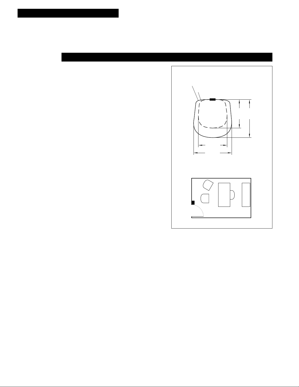
SENSOR
25 (7.6)
20
(6.1)
24
(7.3)
30 (9.1)
feet (meters)
MOTION-AT-DESK COVERAGE
1
⁄2 STEP WALK COVERAGE
INSTALLATION
Coverage
The RSEN-W12 is designed for offices or small rooms up to
300 square feet. Although total coverage of minor motion is
450 square feet, wall switches are normally mounted off-center
in a room which reduces the coverage attainable.
Basic Installation Steps
1. Turn off power at the circuit breaker.
2. Wire and mount the switch in standard junction box.
3. Restore power to the circuit.
4. Adjust settings and test.
Location
When installing the RSEN-W12 in a new junction box, choose
the switch location carefully to provide optimum coverage of
the occupied area. When replacing an existing wall switch,
bear in mind that there must be a clear line of sight between
the sensor and the area to be covered. Avoid pointing the
switch directly into the hallway where it may detect passers-by.
Mounting
CAUTION: Before installing or performing any service
on an RSEN-W12, power must be turned off at the
circuit breaker panel.
Sensor Coverage
Sensor Location
S
2
The RSEN-W12 can replace one switch in any standard single
or double gang box. It may be installed in the same manner as
an ordinary wall switch. Wire the RSEN-W12 as described in
the wiring section.
Ratings
120 VAC Ballast or Tungsten
Maximum Load: 800 Watts
Minimum Load: One ballast or one incandescent lamp
277 VAC Ballast only
Maximum Load: 1200 Watts
Minimum Load: One ballast
Wiring
CAUTION: The RSEN-W12 is designed for use with
either 120 VAC or 277 VAC only. Do not use with any
other voltage. Do not wire to control receptacle circuits.
Verify that the connected load does not exceed the RSEN-W12
ratings. Use twist-on wire connectors for all connections. All
installations should be in compliance with the NEC and all
state and local electrical codes. The RSEN-W12 can be wired
to control both an exhaust fan and lighting provided the total
load does not exceed the maximum load rating (in Amps) for
the automatic wall switch.
10' x 15' OFFICE
One Circuit – One Lighting Load: Connect one wire to the
switchleg for the load. Connect the other wire to the hot lead.
Connections are not polarity sensitive.
One Circuit – Two Lighting Loads: The combination of
Load 1 and Load 2 must not exceed the maximum load rating.
Consult with the building manager and occupant to determine
which lights should be off (Load 2) when the toggle switch
adjacent to the RSEN-W12 is open (OFF).
Caution: If a room is wired for two circuits using two
separate hot leads, it is very important to connect only
one circuit to the RSEN-W12. Split one circuit into two
switchlegs and cap the unused hot lead inside the box.
The RSEN-W12 must always control Load 1, while its control
of Load 2 is selected manually by opening and closing the
toggle switch. Connect one wire to the switchleg for Load 1
and one side of the toggle switch for Load 2. Finally, connect
the other wire from the RSEN-W12 to the hot lead. Connections are not polarity sensitive.
Page 3

INSTALLATION (CONTINUED)
Catalog Number: RSEN-W12
Sensor Wiring
120 VAC OR 277 VAC
NEUTRAL
LOAD 1
LOAD 1
SWITCH LEG
Sensor Adjustment
Switch to M for Manual On
Switch to A for Auto On
Sensitivity
Adjustments,
clockwise
minimum
to
maximum
Range
Area Entry
M A
Time
Delay
1/4 30
TOGGLE
SWITCH
(OPTIONAL)RSEN-W12
LOAD 2
LOAD 2
SWITCH LEG
Time Delay
Adjustment,
clockwise
15 seconds
to
30 minutes
Checkout and Adjustment
Once installation is complete, restore power to the lighting
circuit. Proper operation of the RSEN-W12 must be verified.
Adjustments should be made with the HVAC system on.
Use only insulated tools to make adjustments.
1. Adjustment controls are under the touchplate. “Time
Delay” ranges from 15 seconds (for testing) to 30 minutes.
Using a small screwdriver, set “Time Delay” to 15 seconds
by turning the control completely counterclockwise until it
stops at minimum setting (approximately 8 o’clock). Turn
control for “Area Range” until flat edge of control is at 10
o’clock. Turn “Entry Range” until flat edge of control is at 9
o’clock.
2. Move the “Mode” switch to the “Auto” or “A” position.
3. The area of coverage can be determined by watching the
LED indicator on the front of the sensor while moving
around the room. The LED lights only when the sensor
detects motion. Adjust the “Area Range” control to the
lowest setting that provides adequate motion detection of
a person working in the room. Do not set higher than
necessary.
4. Leave the room. The lights should go out in approximately
15 seconds. Wait at least 12 seconds after the lights go
out. Walk normally back into the room and verify that the
lights turn on automatically. If not, the “Entry Range”
should be increased slightly. Do not set higher than
necessary.
5. If the LED blinks when there is no movement in the room, it
is possible that the sensor is being activated by air flow
from the HVAC system. Reduce the “Area Range” setting
until the LED goes off and stays off with no motion.
6. If the sensor is activated by passers-by in the hallway,
reduce the “Entry Range” setting.
7. Set “Time Delay” to the desired setting for normal use. If
lights go out while the room is occupied, increase setting
slightly until an optimum interval is obtained. Recommended time delay is usually 6-8 minutes (approximately
10 o’clock). People who remain very still for long periods
may need a longer time delay.
8. If preferred, the RSEN-W12 may be set to Manual ON for
maximum energy savings by moving the “Mode” switch to
the “M” position. In this setting, the occupant must push
the touchplate to turn on lights upon entering the room.
3
Page 4

Catalog Number: RSEN-W12
TROUBLESHOOTING
Emergency Manual ON
An override jumper is located underneath the touchplate. This
jumper should remain in place at all times, except in the event
of unit malfunction. Remove the jumper to bypass the sensor
and turn the lights on.
LED Will Not Go On
Verify that the lighting circuit has power. Verify that the sensor
is properly adjusted. Press the touchplate to turn on the lights
manually. If the LED does not light, replace the RSEN-W12.
Lights Will Not Turn ON
• If the lights will not turn on automatically after someone
enters the room, press the touchplate to see if lights will
turn on. If so, the RSEN-W12 could be set to Manual ON
mode. Check under the touchplate to verify the setting.
• If set to Automatic ON mode, the sensor may have been
overridden by someone pressing the touchplate; allow the
RSEN-W12 to time out to verify normal operation.
• If the lights do not turn on after pressing the touchplate,
confirm that no other switches or equipment are interrupting or bypassing power to the sensor or the load.
• If lights still do not turn on, replace the RSEN-W12.
Emergency Service or Support (888) 852-2778
Lights Will Not Turn OFF
• If lights will not turn off after the set time delay, and the
LED has not lit during the time period, press the touchplate
to turn off the lights manually.
• If lights turn off, refer to items 5 and 6 under “Checkout
and Adjustment.”
• If lights do not turn off, verify that the override jumper
under the touchplate has not been removed.
• Confirm that no other switches or equipment are interrupting or bypassing power to the RSEN-W12 or the load.
• If lights still do not turn off, replace the RSEN-W12.
GE Lighting Controls, 41 Woodford Ave., Plainville, CT 06062
Made in U.S.A.
4
 Loading...