

Page 1
Icemaker Accessory Kit
ge.com
Kit IM-6
This kit fits most models calling
for UK-KIT-1, UK-KIT-2, UK-KIT-4,
and all models calling for Kit IM-1,
IM-2, IM-3, IM-4 or IM5SS. If you
are replacing an icemaker with
Kit IM-1 or IM-2, see page 5.
IM-6
197D6260P003 49-60554 12-07 JR
Safety Information . . . . . . . . . 1
Operating Instructions . . . . .2
Before You Call For Service . . . . .3, 4
Normal Sounds You May Hear . . . .2
Preparing for Vacation . . . . . . . . . .2
When You Should Set the
Icemaker Power Switch
to OFF . . . . . . . . . . . . . . . . . . . . . . . . . .2
Installation Instructions
Cold Water Line . . . . . . . . . . . .66–69
Fill Tube Templates . . . . . . . . . . . . .70
Fill Tube Extension
Templates . . . . . . . . . . . . . . . . . . . . .71
Icemaker . . . . . . . . . . . . . . .10–13
Icemaker . . . . . . . . . . . . . . .14–17
Icemaker . . . . . . . . . . . . . . .18–21
Icemaker . . . . . . . . . . . . . . .22–25
Icemaker . . . . . . . . . . . . . . .26–29
Icemaker . . . . . . . . . . . . . . .30–33
Icemaker . . . . . . . . . . . . . . .34–37
Icemaker . . . . . . . . . . . . . . .38–41
Icemaker . . . . . . . . . . . . . . .42–45
Icemaker . . . . . . . . . . . . . . .46–49
Icemaker . . . . . . . . . . . . . . .50–53
Icemaker . . . . . . . . . . . . . . .54–57
Icemaker . . . . . . . . . . . . . . .58–61
Icemaker . . . . . . . . . . . . . . .62–65
Parts List . . . . . . . . . . . . . . . . . . . . .6, 7
Removing Existing
Ice Cube Tray Holder . . . . . . . . . . . .8
Repositioning or Removing
the Freezer Shelf . . . . . . . . . . . . . . . .9
Consumer Support
Consumer Support . . . . Back Cover
Warranty . . . . . . . . . . . . . . . . . . . . . 72
T
S
R
Q
P
N
M
L
K
J
H
G
F
C
Which instructions should
you follow?
Look for a label on the back of the
refrigerator that will tell you which
instructions to use:
or
TSRQPN
MLKJHGFC
Machine à glaçons
Trousse
Máquina de Hielos
Equipo de Accesorios
Manuel d’utilisation
et d’installation
Owner’s Manual and
Installation Instructions
Manual del propietario
e instalación
La section française commence à la page 73
La sección en español empieza en la página 159
★
Page 2
READ AND FOLLOW THIS SAFETY INFORMATION CAREFULLY.
READ AND SAVE THESE INSTRUCTIONS
SAFETY PRECAUTIONS
IMPORTANT SAFETY INFORMATION.
READ ALL INSTRUCTIONS BEFORE USING.
FOR YOUR SAFETY:
Do not place fingers or hands in the automatic
icemaking mechanism while the refrigerator is
plugged in. This will help protect you from
possible injury.
It will also prevent interference with moving parts
of the ejector mechanism and the heating element
that releases the cubes, located on the bottom of
the icemaker.
1
Page 3
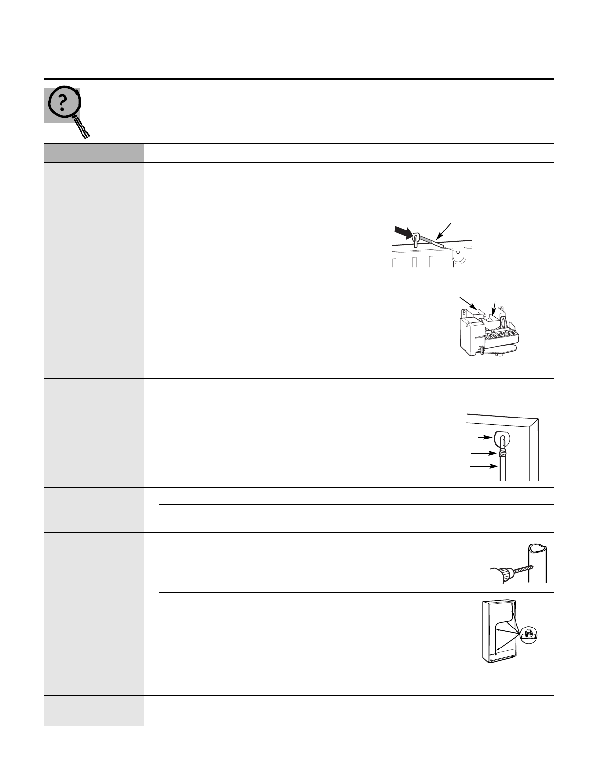
■ The icemaker water valve will buzz when the
icemaker fills with water. If the power switch
is in the ON position, it will buzz even if it has
not yet been hooked up to water. Keeping
the power switch in the ON position before
it is hooked up to water can damage the
icemaker. To prevent this, move the power
switch to the OFF position. This will stop
the buzzing.
■ The sound of cubes dropping into the bin
and water running in the pipes as the
icemaker refills.
About the automatic icemaker.
A newly-installed refrigerator may take 12 to 24 hours to begin making ice.
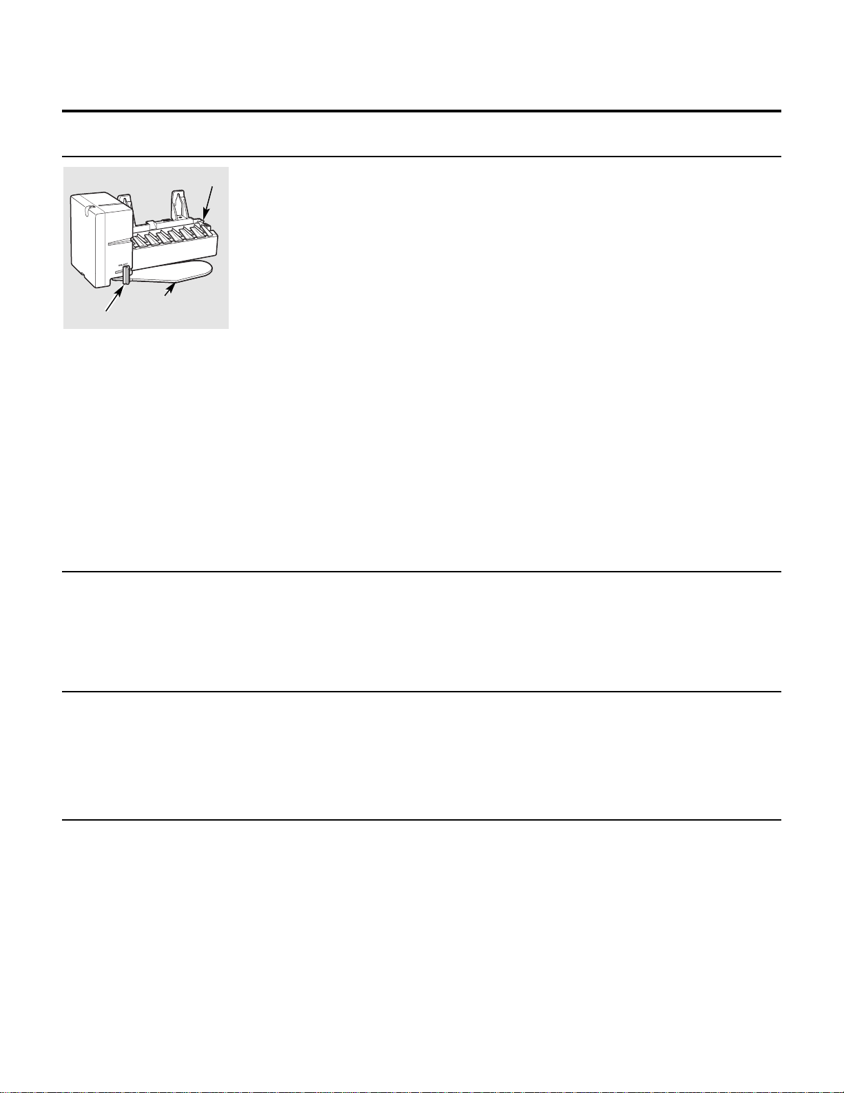
Icemaker
Feeler Arm
Automatic Icemaker
The icemaker will produce seven cubes
per cycle—approximately 100–130 cubes
in a 24-hour period, depending on freezer
compartment temperature, room
temperature, number of door openings
and other use conditions.
If the refrigerator is operated before the
water connection is made to the icemaker,
set the power switch to OFF.
When the refrigerator has been connected
to the water supply, set the power switch
to ON.
The icemaker will fill with water when
it cools to freezing. A newly-installed
refrigerator may take 12 to 24 hours
to begin making ice cubes.
Throw away the first few batches of ice to
allow the water line to clear.
Be sure nothing interferes with the sweep
of the feeler arm.
When the bin fills to the level of the feeler
arm, the icemaker will stop producing ice.
It is normal for several cubes to be joined
together.
If ice is not used frequently, old ice cubes
will become cloudy, taste stale and shrink.
NOTE: In homes with lower-than-average
water pressure, you may hear the icemaker
cycle multiple times when making one batch
of ice.
Power Switch
Preparing for Vacation
Set the icemaker power switch to OFF
and shut off the water supply to the
refrigerator.
If the temperature can drop below freezing,
have a qualified servicer drain the water
supply system (on some models) to prevent
serious property damage due to flooding.
When you should set the icemaker power switch to OFF
■ When the ice storage bin is removed for
more than a minute or two.
■ When the water supply will be shut off for
several hours.
■ When the refrigerator will not be used for
several days.
Normal sounds you may hear
2
(Appearance may vary)
Page 4
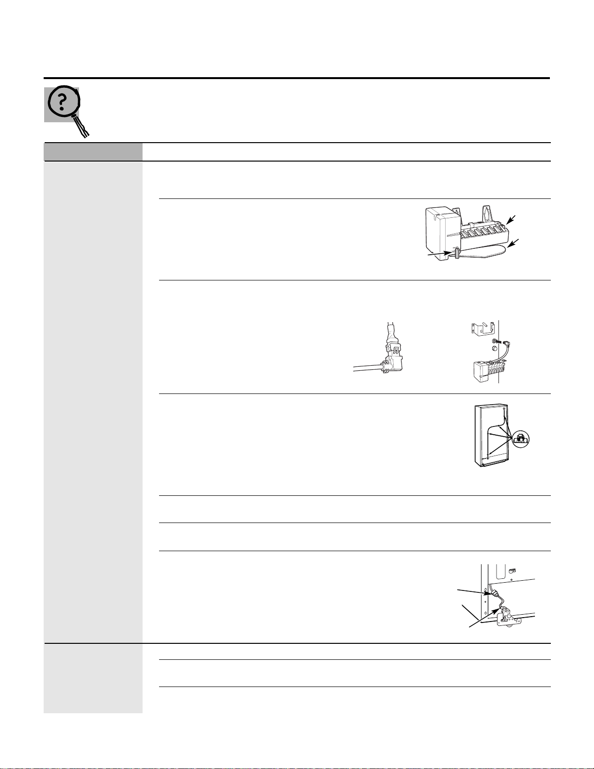
Problem Possible Causes What To Do
Automatic icemaker Freezer compartment too warm. • After installing the kit, allow the refrigerator to completely
does not work/ cool down for 24 hours. Once the compartment is cool,
not making ice the icemaker will begin ice production.
Icemaker is not turned on. • Move the icemaker
power switch to the
ON position.
Icemaker is not plugged • Check that the power cord adapter is fully connected.
in correctly. Also check that the icemaker power cord plug is fully
inserted into the socket. See Plug in the icemaker.
Water line is kinked. • Check that the plastic water line
running from the valve to the
water tube inlet is not kinked.
See Connect the water line. A kink
in the line will restrict water flow
to the icemaker.
Water supply turned off or • After installing the kit, make sure the house water supply
not connected. to the refrigerator has been turned on.
Piled up cubes in the storage bin • Level cubes by hand.
cause the icemaker to shut off.
Water valve is not plugged • Check that the valve wire
in correctly. adapter is completely
plugged onto the male
connector plug and the
terminals on the water
valve. See Attach the
water valve.
Ice cubes have Ice storage bin needs cleaning. • Empty and wash bin. Discard old cubes.
odor/taste
Food transmitting odor/taste • Wrap foods well.
to ice cubes.
Interior of refrigerator • See Care and cleaning.
needs cleaning.
Before you call for service… ge.com
Troubleshooting Tips
Save time and money! Review the charts on the following
pages first and you may not need to call for service.
Male
Connector
Plug
Valve Terminals
3
Feeler
Arm
Power
Switch
Icemaker
(Appearance may vary)
Adhesive-backed Fasteners
for Water Tube
Page 5
Problem Possible Causes What To Do
Leaking water around Foam in the fill cup from • If the fill tube was installed by sliding it through the back
the fill cup installing the fill tube. of the refrigerator, it may have picked up pieces of foam as
it was pushed through. This foam can interfere with the
water flow in the fill cup. Check the fill cup to make sure
there are no foam pieces.
Fill tube not correctly seated • Check that the fill tube is
in fill cup. correctly inserted in the
fill cup opening. See
Mount the icemaker.
Leaking water House supply not properly • Check that the house supply is firmly attached to the water
behind refrigerator connected to the water valve. valve. See Water line installation instructions.
Water line not connected to the • Check that the plastic
water tube inlet. water line running from
the valve to the water
tube inlet is firmly
attached with the hose
clamp. See Connect the
water line.
Slow ice/freezer not Door left open. • Check to see if package is holding door open.
cold enough
Temperature control not • See About the Temperature Control.
set cold enough.
Ice cubes too small/ Water shutoff valve connecting • We recommend drilling a 1/4″ hole
slow ice refrigerator to house water line in the water pipe to connect the water
may be clogged. shutoff valve. Failure to drill a 1/4″ hole
may result in reduced ice production or
smaller cubes. See Installing the water line.
Water line is kinked. • Check that the plastic
water line running from
the valve to the water tube
inlet is not kinked. See
Mount the icemaker. A kink
in the line will restrict water
flow to the icemaker.
Frequent “buzzing” sound
Normal operation. • During normal opeation, the water valve will “buzz”
when the icemaker fills with water.
Before you call for service…
Troubleshooting Tips
4
Fill Tube
Fill Tube
Fill Cup
Water Tube Inlet
Hose Clamp
Water Line
Drill 1/4″
Hole in
Water Pipe
Adhesive-backed Fasteners
for Water Tube
(Appearance may vary)
Page 6
5
BEFORE YOU BEGIN
Installation IM-6 Icemaker Kit
Instructions
Read these instructions completely and carefully.
•
IMPORTANT – Save these instructions
for local inspector’s use.
•
IMPORTANT – Observe all governing
codes and ordinances.
• Note to Installer – Be sure to leave these
instructions with the Consumer.
• Note to Consumer – Keep these instructions
for future reference.
• Skill level – Installation of this appliance requires
basic mechanical and electrical skills.
• Completion time – 20–60 minutes
• Proper installation is the responsibility of the installer.
• Product failure due to improper installation is
not covered under the Warranty.
It’s important that you use the water valve and fill tube
extension that come with this kit, even though your
refrigerator may already have them installed.
The old valve will not allow enough water through to
fill the icemaker properly and cause damage.
The fill tube extension needs to be a different length
than the original tube for proper water flow. Cut the tube
to the length indicated for your model of refrigerator.
ARE YOU REPLACING AN
ICEMAKER WITH THIS KIT?
Questions? Call 800.GE.CARES (800.432.2737) or Visit our Website at: ge.com
In Canada, call 1.800.561.3344 or Visit our Website at: geappliances.ca
There is a label on the back of the refrigerator
that will tell you whether to use Instructions:
or
Pages 10–65 contain fourteen different Installation
Instructions.
The actual installation of the icemaker will depend on which
model refrigerator you have.
TSRQPNMLKJHGFC
WHICH INSTRUCTIONS SHOULD YOU
FOLLOW?
• If the unit is damaged in shipment, return the unit
to the store in which it was bought for repair or
replacement.
• If the unit is damaged by the customer, repair or
replacement is the responsibility of the customer.
• If the unit is damaged by the installer (if other than
the customer), repair or replacement must be made
by arrangement between customer and installer.
DAMAGE – SHIPMENT/INSTALLATION
Page 7
6
Installation Instructions
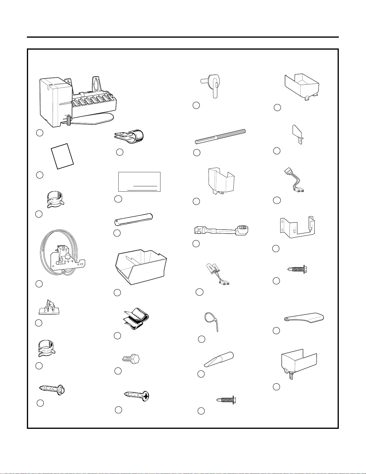
CONTENTS OF KIT IM-6
6
3
Owner’s Manual &
Installation Instructions
2
Ice Bucket
11
Water Line Clamp
(strain relief)
8
Water Line Clamp
(strain relief)
12
Hex-Head Screw for
Water Line Clamp
7
Water Valve and
Tube Assembly
4
Hose Clamp
(black)
Hose Clamp
(not black)
Hex-Head
Screw
13
Adhesive-Backed
Water Line Fasteners
5
15
Water Tube Inlet
14
Phillips Head
Screws (2)
Warranty Label
9
ICEMAKER
WARRANTY VERIFICATION
Date Installed
Dealer
Fill Tube Extension
(3/4″ O.D. [20 mm])
10
18
17
Fill Tube with Foil
(5/8″ O.D.)
16
Icemaker Fill Cup
(side-mounted)
Icemaker Power Cord
Adapter (4 pin)
Water Valve
Wire Extension
19
Wire Ties (2)
20
Icemaker
(Appearance may vary)
1
Installation
Instructions
Hex-Head Screw (2)
22
Icemaker Bracket
26
Screws to Install
Bracket to Refrig.
Wall (3)
27
Icemaker Fill Cup
(center-mounted)
23
Icemaker Insert
24
Insulated Fill Tube
(5/8″ O.D.)
21
Water Valve
Wire Adapter
25
Icemaker Fill Cup
(end-mounted –
2-3/4″ long)
29
Feeler Arm (Curved)
28
Page 8
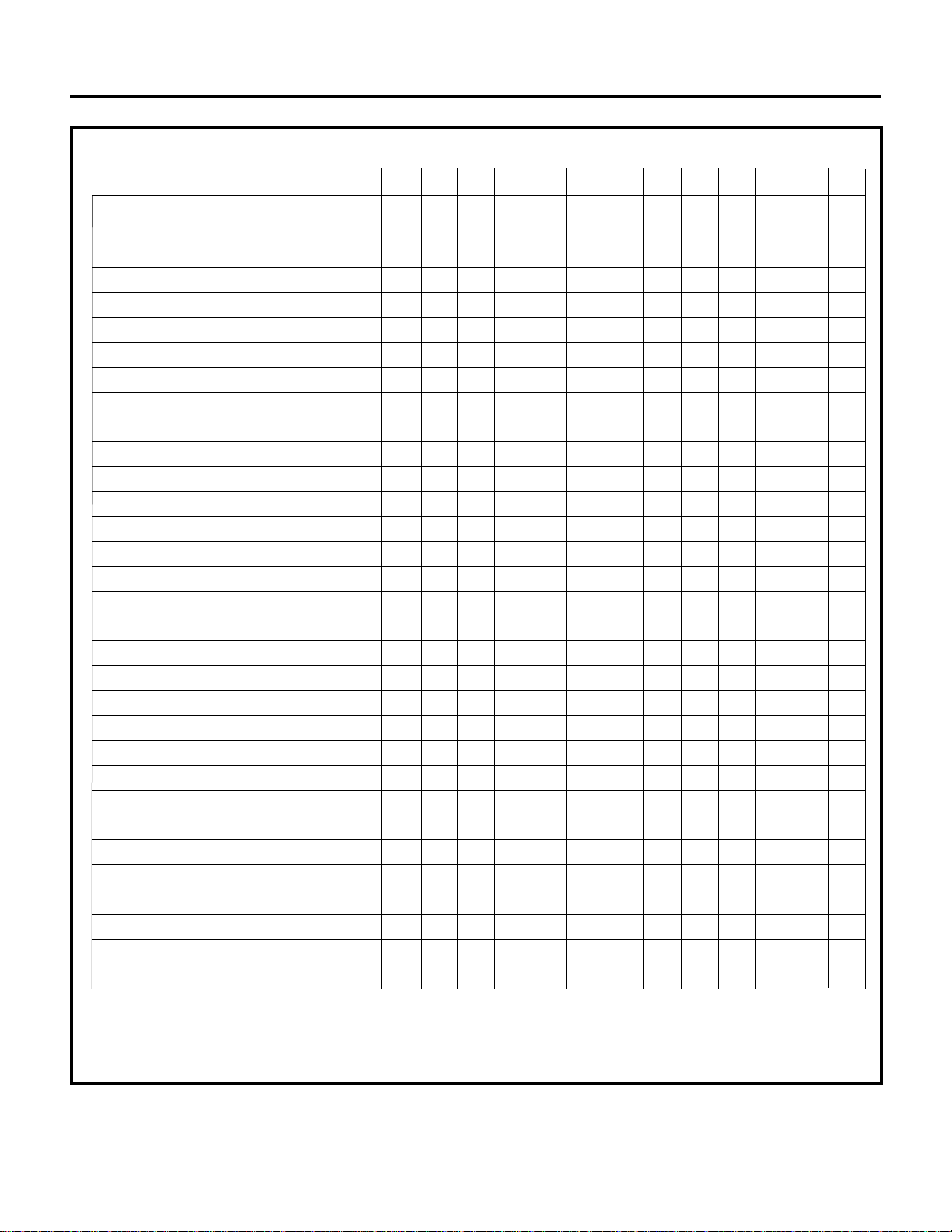
Parts List Use with Installation Instructions:
CFGHJKLMNPQRST
1 Icemaker XXXXXXX XXXXXXX
2 Owner’s Manual and
Installation Instructions
XXXXXXX XXXXXXX
3 Hose Clamp (black) XXXX XX XXX XX
4 Water Valve and Tube Assembly* XXXXXXXXXXXXXX
5
Adhesive-Backed Water Line Fasteners
XXXXXXX XXXXXXX
6 Hose Clamp (not black) XXX XX XX
7
Hex-Head Screw for Water Line Clamp
XX X XX XXX XX
8 Water Line Clamp (strain relief) XXX XXXXXXXXX
9 Warranty Label XXXXXXX XXXXXXX
10 Fill Tube Extension (3/4″ O.D.) XXX X XX
11 Ice Bucket XXXX XXXXXX
12 Water Line Clamp (strain relief) XX
13 Hex-Head Screw X XXXXX XXXXXXX
14 Phillips Head Screw (2) XX XXXXX
15 Water Tube Inlet XXXX XX XXX X
16 Fill Tube with Foil (5/8″ O.D.) XX X XX X XX X
17 Icemaker Fill Cup (side-mounted) XXXXX X XXXXXX
18
Icemaker Power Cord Adapter (4 pin)
XXXXX X
19 Water Valve wire extension X
20 Wire Ties (2) XXXXXXX XXXXX
21 Insulated Fill Tube (5/8″ O.D.) X
22 Hex-Head Screw (2) X
23
Icemaker Fill Cup (center-mounted)
X
24 Icemaker Insert X
25 Water Valve Wire Adapter X
26
Icemaker Bracket (on some models)
X
27 Screws to Install Bracket to X
Refrigerator Wall (3)
28 Feeler Arm (Curved) X
29 Icemaker Fill Cup X
(end-mounted – 2-3/4″ long)
*Always change the water valve when replacing an icemaker that makes round cubes.
This new icemaker uses a different voltage which may cause the old valve to fail.
For dispenser models, order GE Part Number WR57X96.
7
Installation Instructions
Page 9
8
Installation Instructions
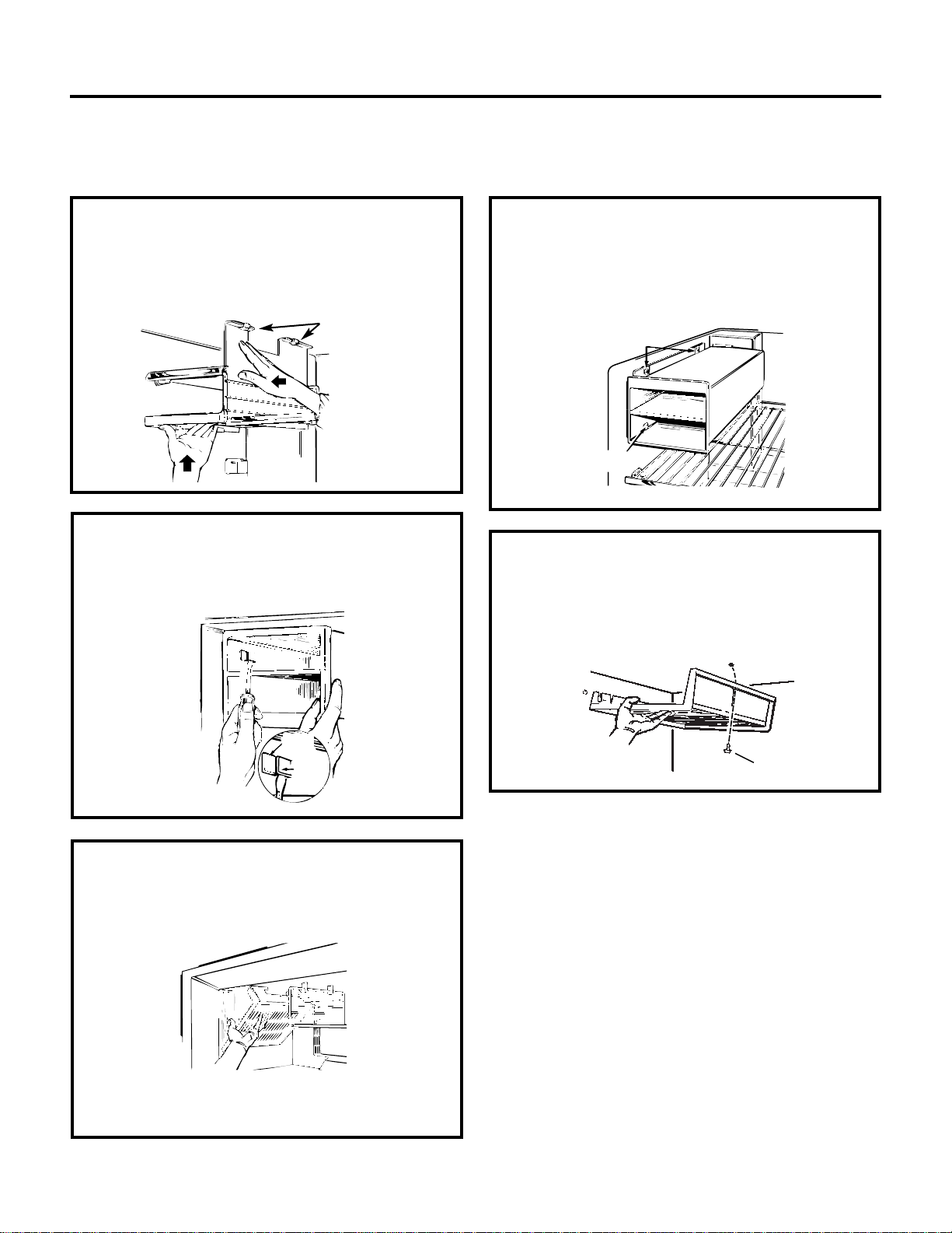
REMOVE EXISTING ICE TRAY HOLDER
Follow the instructions below for the ice tray holder that looks like yours.
Type 1
•Unhook the ice tray holder side and bottom from
the retaining hooks. Lower the holder until the side
is clear of the freezer shelf and remove it from the
freezer. You will not need this part.
Retaining hooks
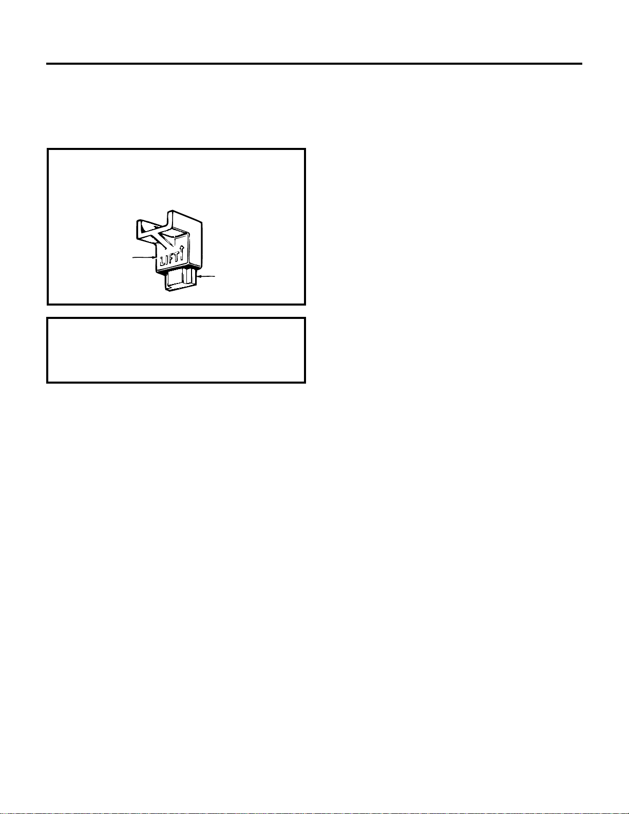
Type 2
•As you lift the tab on the left side in the holder with
the blade of a screwdriver, pull the holder forward
and out. You will not need this part.
Do not
lift here
Lift this
tab out
Type 3
•When following Instructions G, it is not necessary
to remove the ice tray shelf or, on some models,
the wire shelf next to it.
•Tilt the ice tray shelf and remove it. You will not
need this part.
Type 4
•Remove the 2 screws and save them for installation
of the icemaker.
•Lift the ice tray holder off the plastic hook. You will
not need this part.
Screws
Plastic hook
Type 5
•Remove the screw with a 1/4″ nutdriver.
•Pull the ice tray shelf away from the wall. Remove
the shelf. You will not need this part.
•Replace the screw.
Screw
Page 10
9
REPOSITION OR REMOVE FREEZER SHELVES
On some models, you may need to remove or reposition the freezer shelf so the icemaker and
bucket sit properly. Follow the instructions below for the ice tray holder that looks like yours.
Type 1
•To reposition the two-piece shelf supports, slide the
shelf up off the base mount.
Base
mount
Shelf
support
Type 2
•On some bottom-mount no-frost refrigerators, you
need to remove a full width flat freezer shelf before
installing the icemaker.
Installation Instructions
Page 11
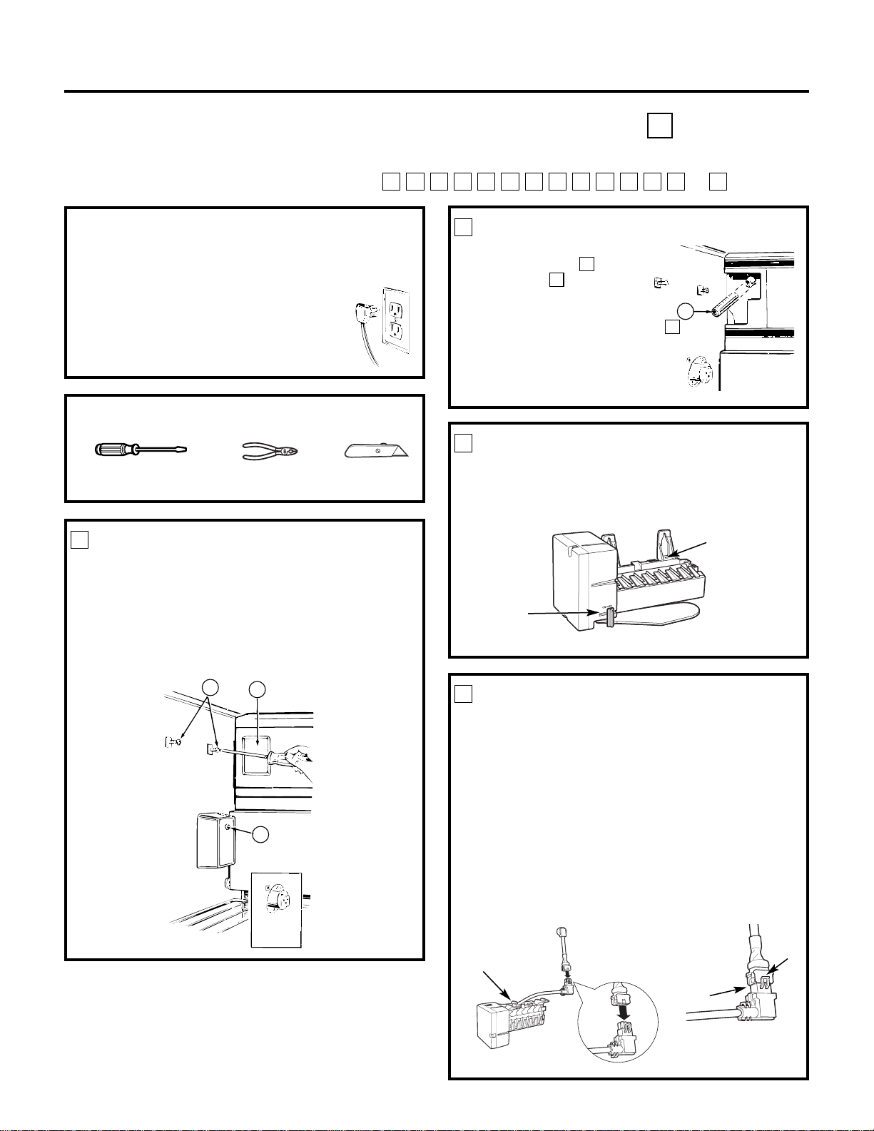
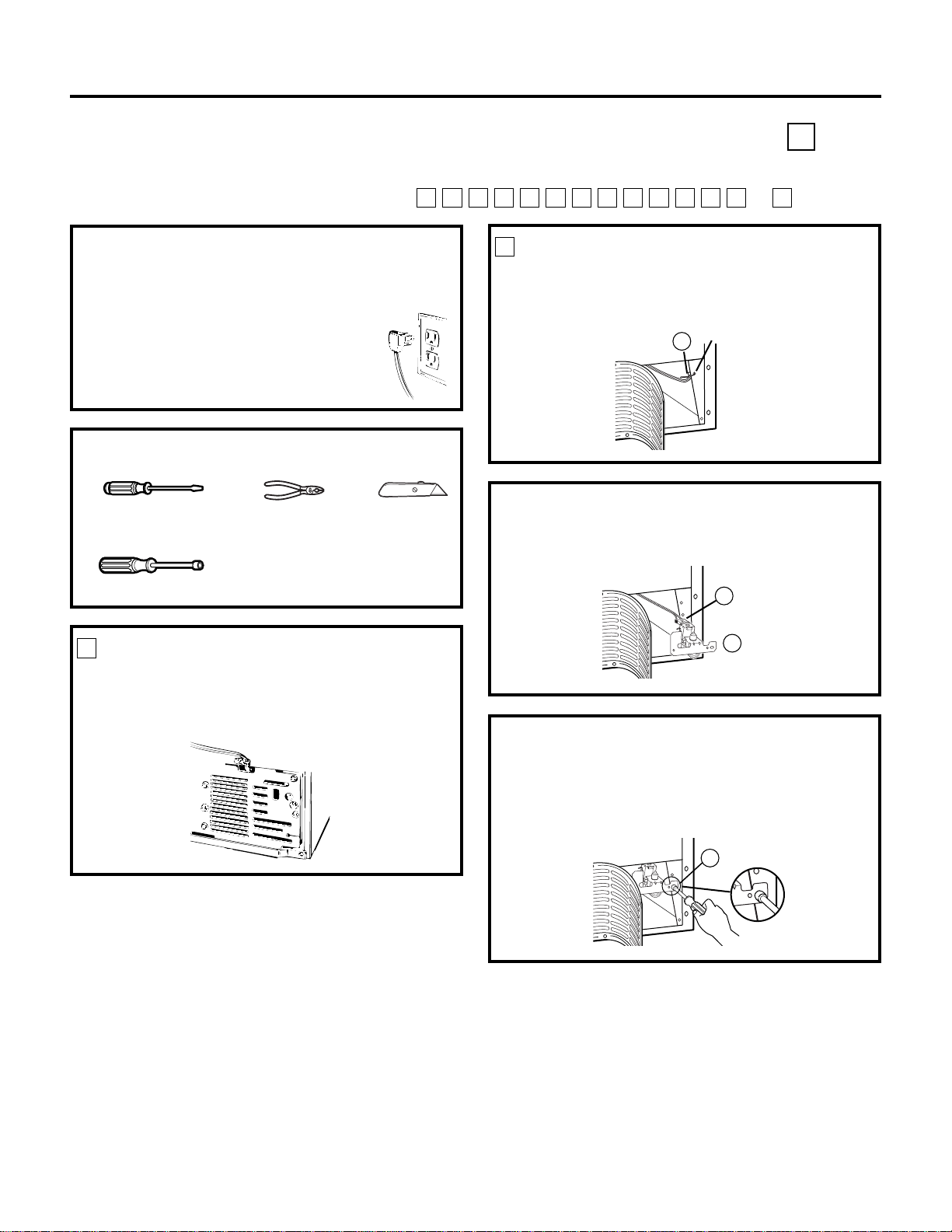
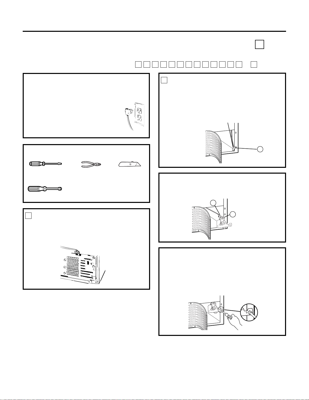
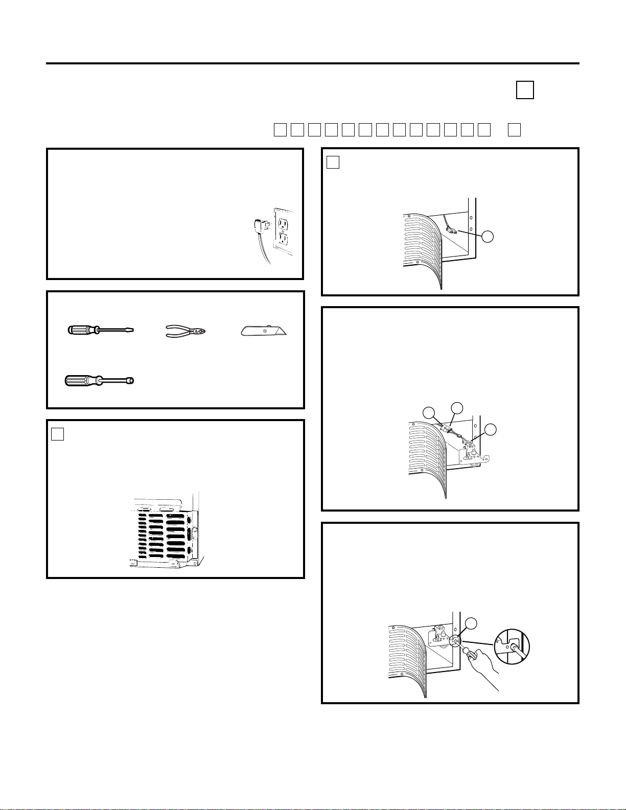
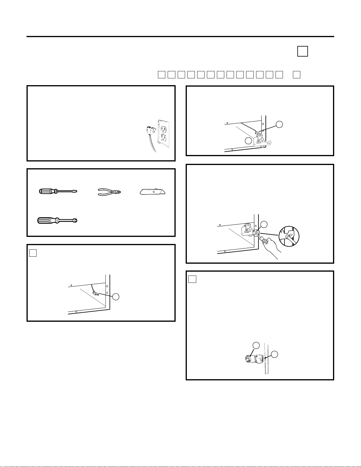
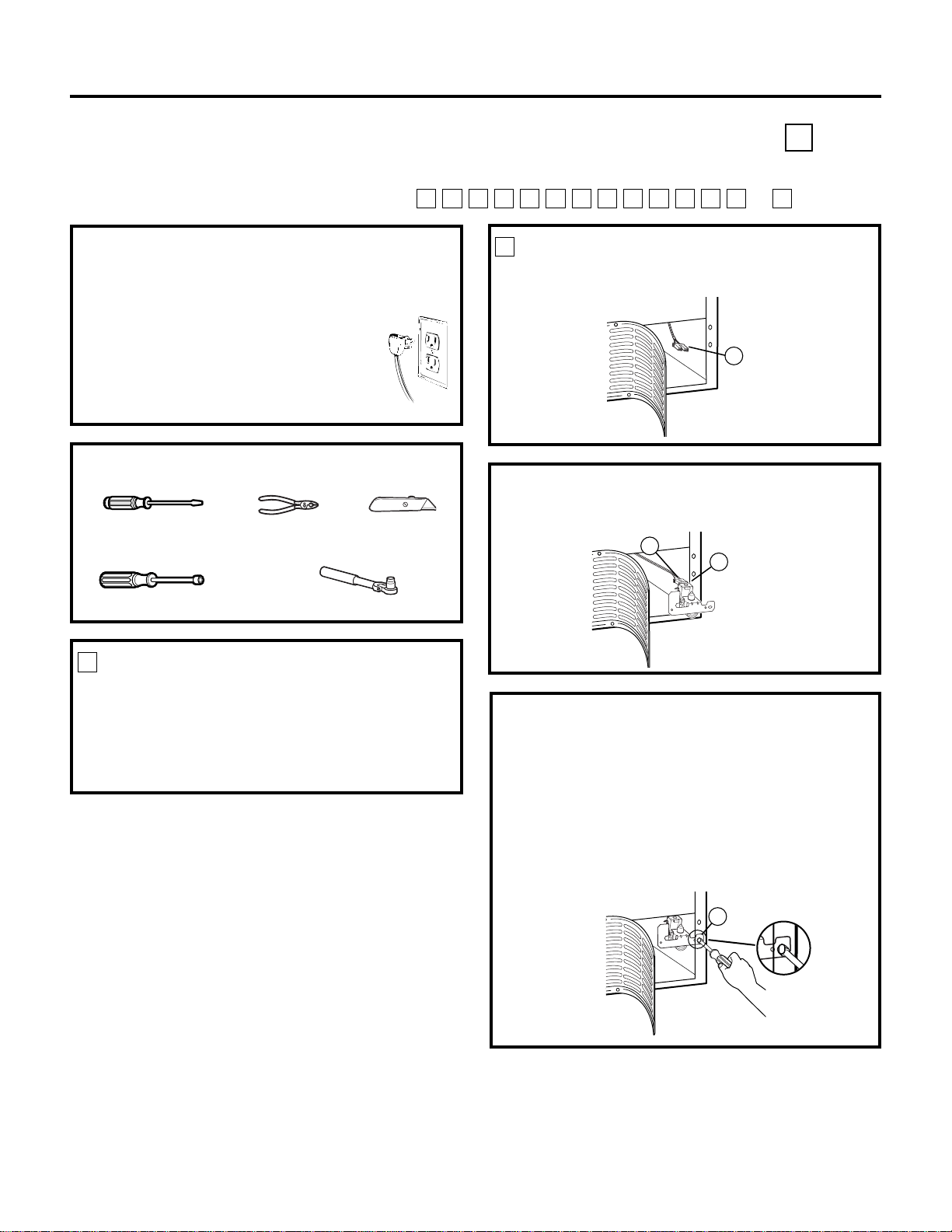
PREPARE FOR INSTALLATION
• Remove the screw (A) that holds the electrical
plug cover in place. You will not need this screw
and cover.
• Remove the light shield insert (B) and discard it.
• Loosen the two mounting screws (C)
approximately 1/2″ (13 mm). DO NOT REMOVE
THESE SCREWS.
INSTALL FILL TUBE EXTENSION
Cut the fill tube extension
(10) to the length
(refer to the
template on page 67) with
a sharp knife or single-edge
razor blade and slide it onto
the fill tube against the stop.
C
C
1
2
Installation Instructions
ICEMAKER INSTALLATION INSTRUCTIONS C
Are these the right instructions for your model? Follow the Installation Instructions indicated by
the label on the back of the refrigerator— or
TSRQPNMLKJHGFC
BEFORE YOU BEGIN
Read each step thoroughly before proceeding.
•
CAUTION –Unplug the
Refrigerator. To eliminate the danger
of electric shock during installation,
you must unplug the refrigerator
from its electrical outlet.
Flat blade and Phillips
screwdrivers
Pliers
TOOLS YOU WILL NEED
Sharp knife
Cover
removed
B
C
A
C
10
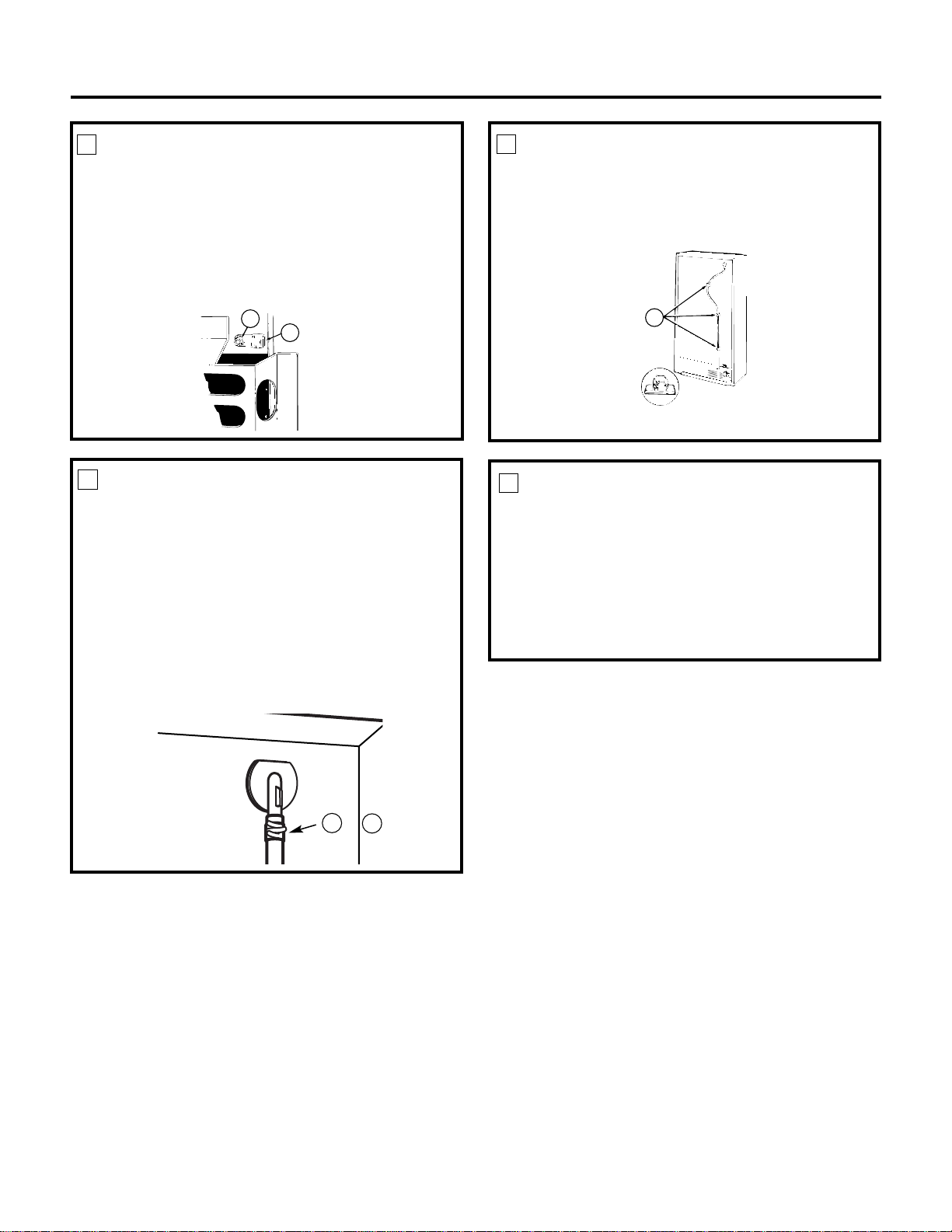
SET POWER SWITCH TO OFF
Set the icemaker power switch to OFF. Leave
the power switch in the OFF position until the
refrigerator is connected to the water supply to
prevent premature operation.
3
Power
Switch
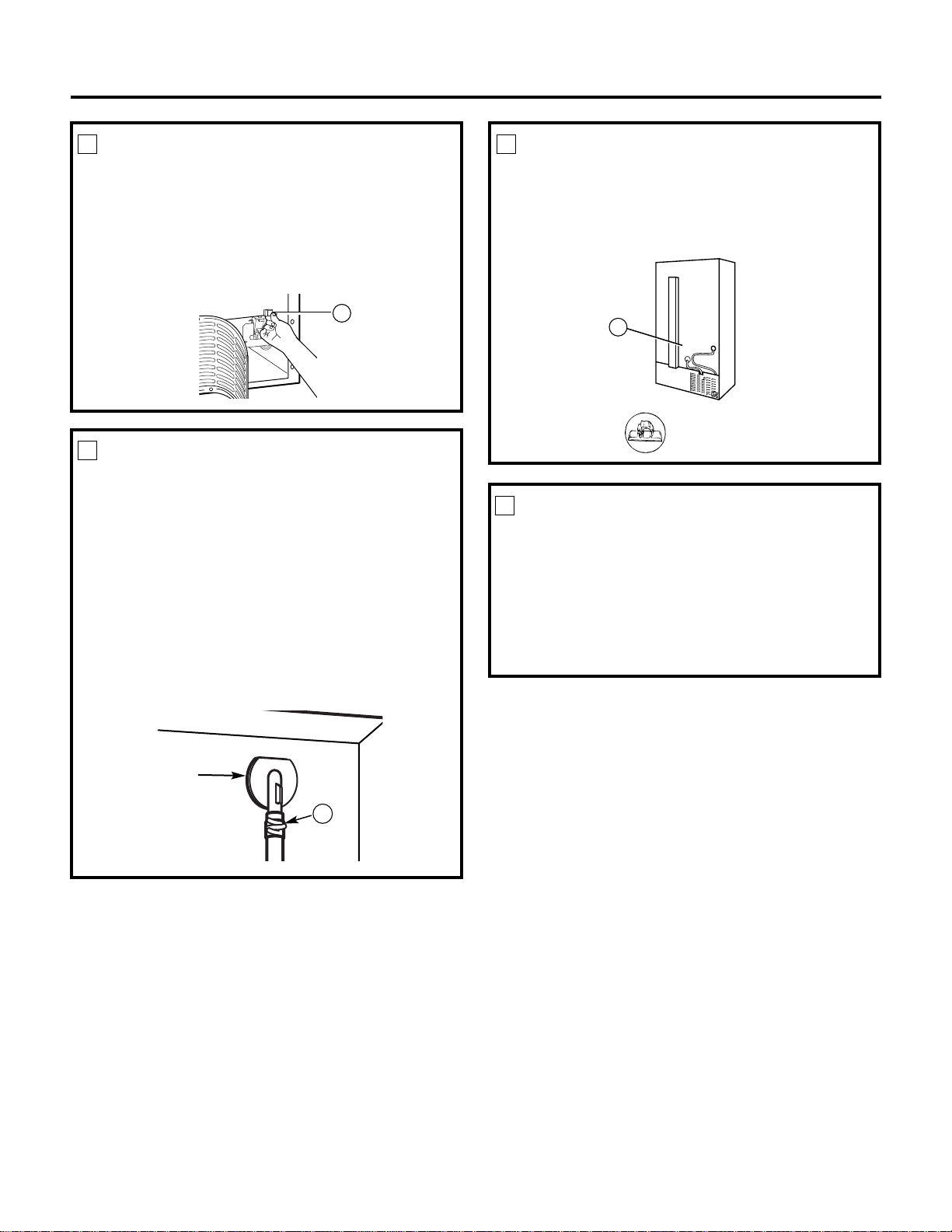
POWER CORD ADAPTER
(on some models)
There is a power cord adapter (18) included with
the kit. Visually inspect to see if the power cord on the
icemaker matches the socket on the side wall of the
freezer compartment. If needed, secure the adapter
to the side of the icemaker power cord. When
connecting the adapter to the power cord, make sure
the seal is in place between the connectors, and ensure
that both connector locks are snapped in place. Secure
the power cord adapter to the icemaker by putting it
into the hook at the back of the icemaker and attaching
it to the icemaker with a wire tie (20).
4
Hook
Hole for
wire tie
Seal
Locks
10
(Appearance may vary)
Page 12
11
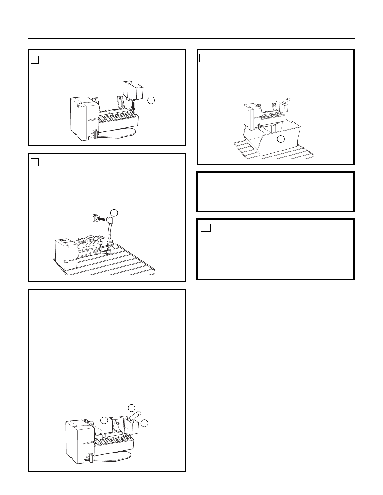
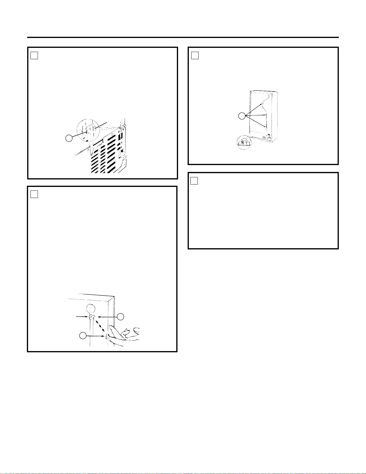
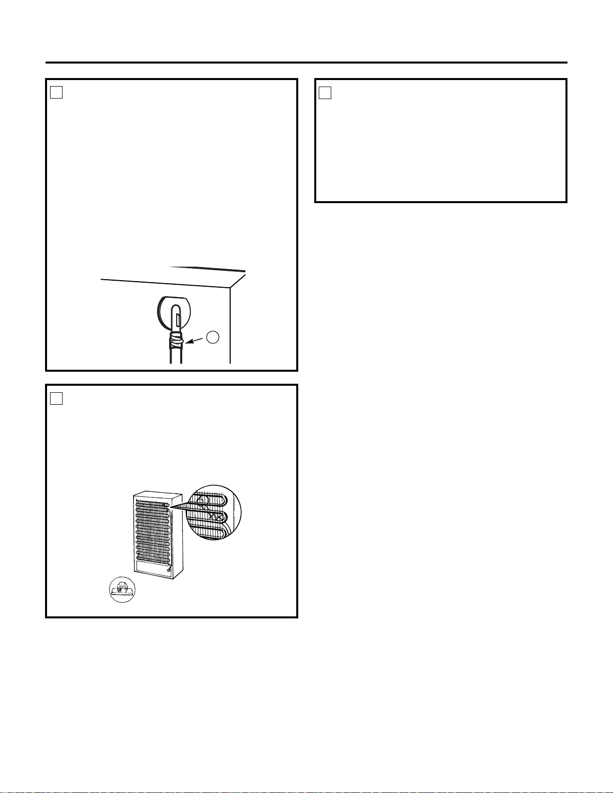
INSTALL THE ICEMAKER FILL CUP
Install the icemaker fill cup (side-mounted) (17) into the
icemaker as shown.
5
17
MOUNT THE ICEMAKER
• Lift the icemaker so the fill tube extension
(10) fits in the fill cup opening (E). Hang the
icemaker on the two mounting screws (C).
Make sure:
• The power cord is still firmly in the socket.
• The fill tube extension (10) is still in the fill cup
opening. (Check the rear of the refrigerator to
make sure the fill tube has not been pushed out
of the back of the refrigerator).
• The icemaker mounting screws are located in
the uppermost position of the mounting slots.
THEN SECURELY TIGHTEN THE ICEMAKER
MOUNTING SCREWS.
7
10
E
C
PLUG IN THE ICEMAKER
Place the icemaker in the freezer compartment on its
side as shown. Insert the icemaker power cord plug
(D) into the socket on the side wall, making sure the
prongs and holes are matched. If holes do not match,
see Step 4. Press the plug firmly into the socket.
6
D
8
11
ATTACH WARRANTY LABEL
A label (9) is provided with this kit to record the date of
installation for warranty purposes. Apply it to the back
of the refrigerator.
9
KEEP THIS MANUAL
The warranty for the icemaker is printed in this
manual. Keep this manual with your Refrigerator
Owner’s Manual.
The icemaker installation inside the freezer is now
complete. Continue to the Water Valve Assembly
section.
10
Installation Instructions
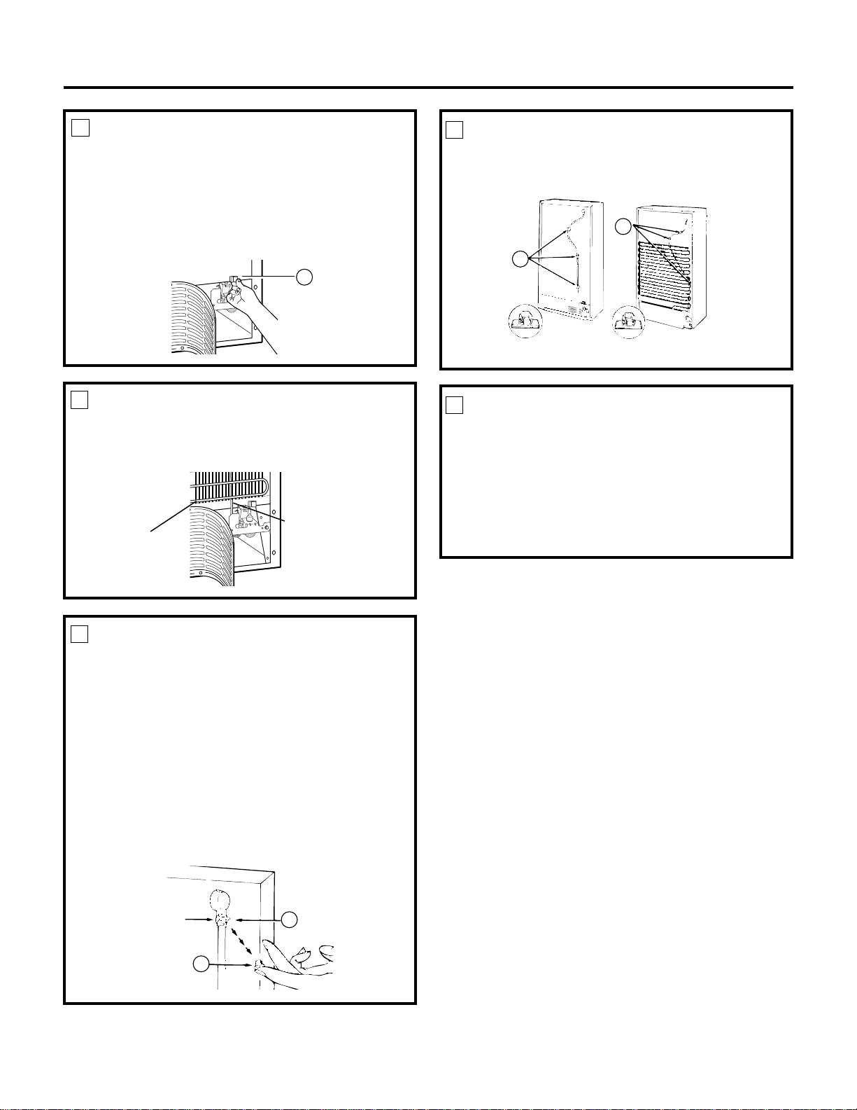
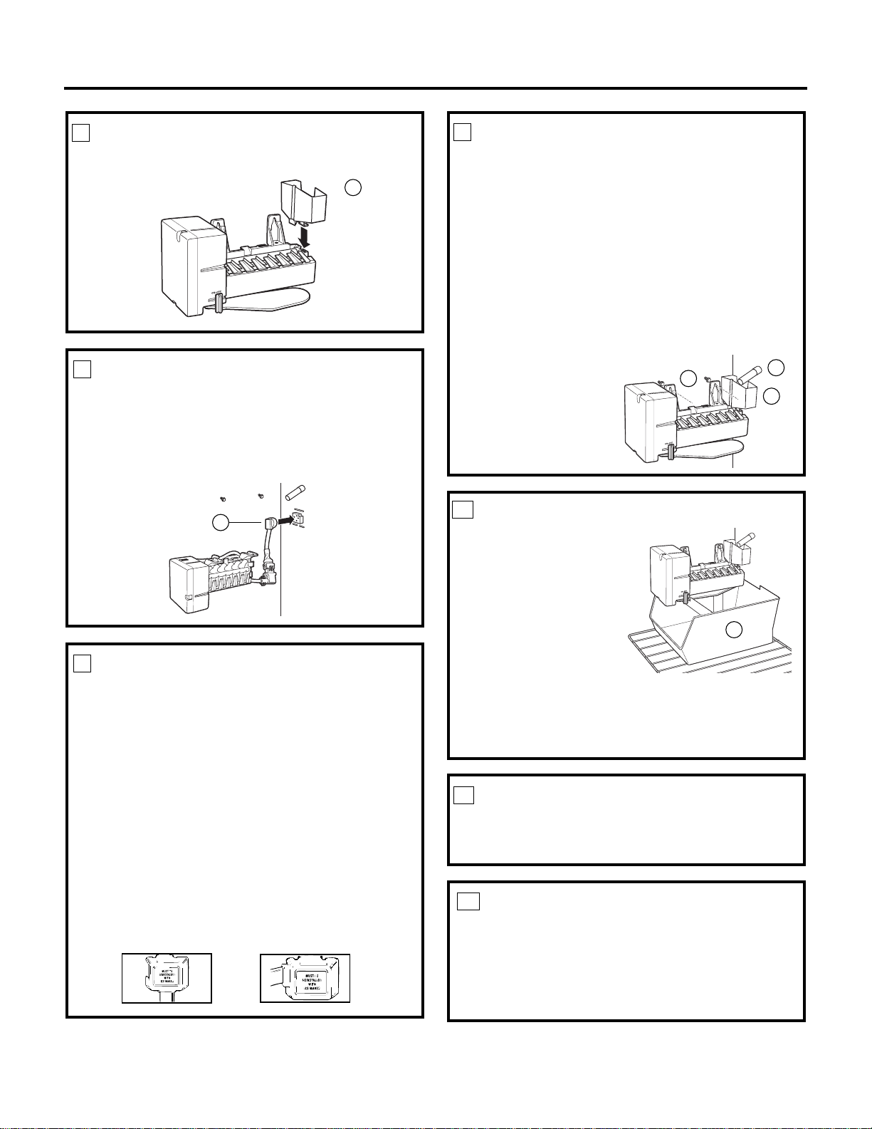
INSTALL THE ICE BUCKET
Put the ice bucket (11) directly under the icemaker
(to the left and all the way to the rear of the shelf
under the icemaker).
Make sure the icemaker power switch is set to OFF.
Page 13
12
REMOVE THE COVER
At the bottom rear of the refrigerator, remove the
screw(s) holding the compressor compartment cover
(if covered) and save for reinstallation later. Bend the
cover back for access to the compartment.
1
BEFORE YOU BEGIN
Read each step thoroughly before proceeding.
•
CAUTION –Unplug the
Refrigerator. To eliminate the danger
of electric shock during installation,
you must unplug the refrigerator
from its electrical outlet.
Flat blade and Phillips
screwdrivers
Pliers
TOOLS YOU WILL NEED
Sharp knife
5/16″ Nutdriver
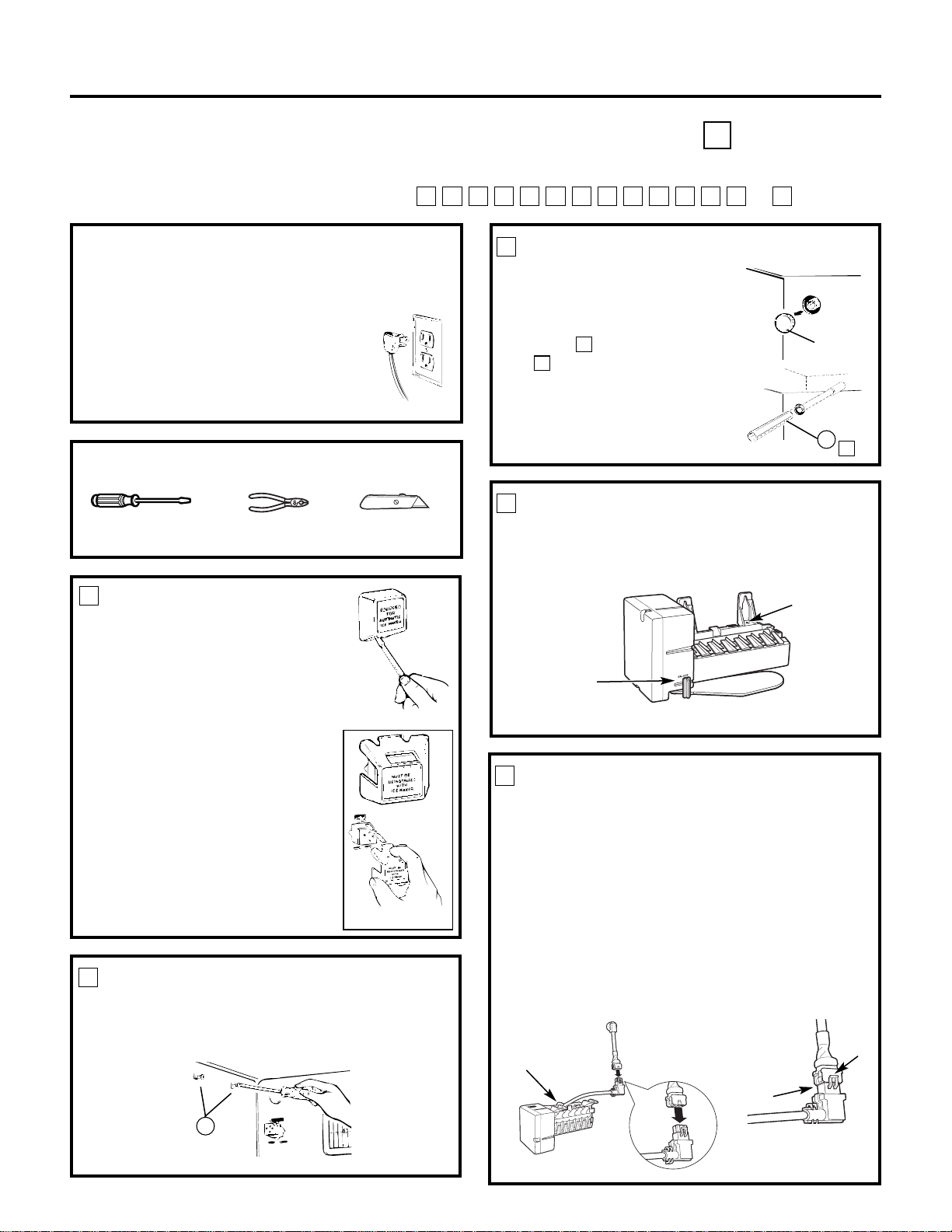
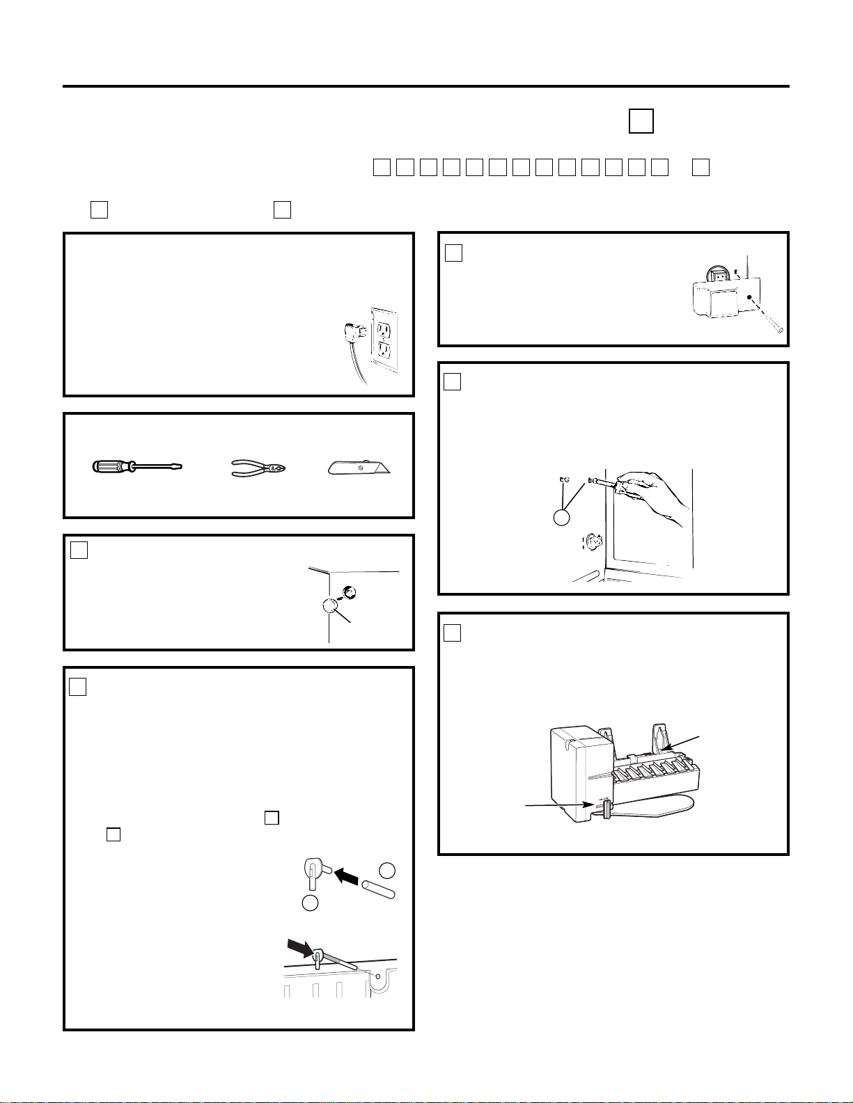
ATTACH THE WATER VALVE
• Locate the female connector plug (A) which is
attached to the cabinet with a wire tie. Remove
the wire tie and discard it.
2
Wire tie
A
4
A
13
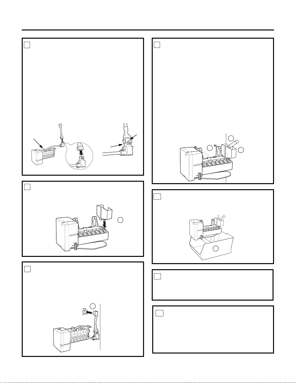
• Remove and discard the tape from the female
connector (A) and plug onto the male terminals
on the water valve (4). Either wire can go on
either terminal.
• Fasten the water valve to the cabinet edge hole
using the hex-head screw (13) from the kit.
DO NOT DRILL ANY ADDITIONAL HOLES.
• Check the plastic water line nut on the bottom
of the water valve to be sure it is hand tight.
DO NOT USE TOOLS.
Installation Instructions
WATER VALVE ASSEMBLY INSTALLATION INSTRUCTIONS C
Are these the right instructions for your model? Follow the Installation Instructions indicated by
the label on the back of the refrigerator— or
TSRQPNMLKJHGFC
Page 14
13
Installation Instructions
INSTALL WATER LINE CLAMP
• Push the metal water line clamp (strain relief) (12)
onto the lower flange of the cabinet back, directly
in line with the water valve.
• The metal clamp is for the house water line. (See
the Water Line Installation Instructions). It is not
to be used for the tubing from the water valve up
to the icemaker.
3
12
ROUTE THE PLASTIC WATER LINE
On models that have condenser tubing on the back
of the cabinet, insert the plastic water line between
the tubing and the back of the cabinet.
4
Condenser
tubing
Plastic water line
CONNECT THE WATER LINE
• Remove the small plastic cap (B) from the bottom
of the water tube inlet located in the upper-right
rear corner of the refrigerator.
• Squeeze the ends of the hose clamp (6) from the
kit with pliers and slide the clamp over the water
tube inlet.
• While still squeezing the clamp, insert the
plastic water line into the inlet as far as it will
go (approximately 1″ [25 mm]).
• Then slide the clamp downward to capture the
plastic water line in place.
• Make sure the fill tube is aimed down.
5
6
Water tube
inlet
B
ATTACH THE PLASTIC WATER LINE
Fasten the plastic water line to the back of the
cabinet with adhesive-backed fasteners (5), spacing
the fasteners as shown to take up the slack in the line.
6
Adhesive-backed fasteners for plastic water line
5
5
WATER VALVE INSTALLED
Refer to the Water Line Installation Instructions for
connection to the home water supply. After water
line installation is completed, set the icemaker
power switch to ON.
The icemaking cycle will not begin until the
icemaker and freezer compartment reach
operating temperature, then icemaking will
begin automatically.
7
Page 15
LOOSEN MOUNTING SCREWS
Loosen the two mounting screws (A) but do not screw
them all the way out. The screws should extend
approximately 1/2″ (13 mm) out from the freezer wall.
INSTALL FILL TUBE EXTENSION
• Remove and discard the white
plug from the upper left corner
of the freezer wall.
• Cut the fill tube extension (10)
to the length (refer to the
template on page 67) with
a sharp knife or a single-edge
razor blade and slide it onto
the fill tube against the stop.
F
F
2
3
Installation Instructions
ICEMAKER INSTALLATION INSTRUCTIONS F
Are these the right instructions for your model? Follow the Installation Instructions indicated by
the label on the back of the refrigerator— or
TSRQPNMLKJHGFC
BEFORE YOU BEGIN
Read each step thoroughly before proceeding.
•
CAUTION –Unplug the
Refrigerator. To eliminate the danger
of electric shock during installation,
you must unplug the refrigerator
from its electrical outlet.
Flat blade and Phillips
screwdrivers
Pliers
TOOLS YOU WILL NEED
Sharp knife
14
Fig. 1
REMOVE PLUG COVER
Remove the electric plug cover.
To remove the type shown in Fig. 1,
insert a standard screwdriver blade
in slot at bottom of cover, apply
pressure upwards, and pry cover
away from freezer wall. Discard
this cover.
To remove the type shown in
Fig. 2, press top of cover down
to free its upper tab from slot in
freezer wall. Then pull cover
straight out to free the lower tabs
from their slots. Save this cover
for reinstallation later.
1
A
Remove
plug
F
10
SET POWER SWITCH TO OFF
Set the icemaker power switch to OFF. Leave the
power switch in the OFF position until the refrigerator
is connected to the water supply to prevent
premature operation.
4
Power
Switch
Hole for
wire tie
Fig. 2
POWER CORD ADAPTER
(on some models)
There is a power cord adapter (18) included with the
kit. Visually inspect to see if the power cord on the
icemaker matches the socket on the rear wall of the
freezer compartment. If needed, secure the adapter
to the side of the icemaker power cord. When
connecting the adapter to the power cord, make sure
the seal is in place between the connectors, and ensure
that both connector locks are snapped in place. Secure
the power cord adapter to the icemaker by putting it
into the hook at the back of the icemaker and attaching
it to the icemaker with a wire tie (20).
5
Hook
Seal
Locks
(Appearance may vary)
Page 16
15
PLUG IN THE ICEMAKER
Hold the icemaker in the freezer compartment as
shown. Insert the icemaker power cord plug (B)
into the socket on the rear wall, making sure the
prongs and holes are matched. If holes do not
match, see Step 5. Press the plug firmly into
the socket.
7
B
Installation Instructions
MOUNT THE ICEMAKER
• Lift the icemaker so the fill tube extension (10) fits
in the fill cup opening (C). Hang the icemaker on
the two mounting screws (A).
Make sure:
• The power cord is still firmly in the socket.
• The fill tube extension (10) is still in the fill cup
opening. (Check the rear of the refrigerator to
make sure the fill tube has not been pushed out
of the back of the refrigerator.)
• The icemaker mounting screws are located in
the uppermost position of the mounting slots.
THEN SECURELY
TIGHTEN THE
ICEMAKER MOUNTING
SCREWS.
9
INSTALL THE ICEMAKER FILL CUP
Install the icemaker fill cup (side-mounted) (17) into
the icemaker as shown.
6
17
INSTALL THE ICE BUCKET
Put the ice bucket (11)
directly under the
icemaker (to the left
and all the way to the
rear of the shelf under
the icemaker).
The straight 2-
position
shelf should
be in the
lower position.
The step
shelf’s lower step should
be under the icemaker.
The cantilever shelf’s top hooks should be in the
6th slot up from the bottom of the track.
Make sure the icemaker power switch is set to OFF.
10
11
ATTACH WARRANTY LABEL
A label (9) is provided with this kit to record the date
of installation for warranty purposes. Apply it to the
back of the refrigerator.
11
KEEP THIS MANUAL
The warranty for the icemaker is printed in this
manual. Keep this manual with your Refrigerator
Owner’s Manual.
The icemaker installation inside the freezer is now
complete. Continue to the Water Valve Assembly
section.
12
10
A
C
REINSTALL THE ELECTRIC PLUG
COVER
If the plug cover removed in Step 1 matched
Figure 1, continue to Step 9.
If the plug cover removed in Step 1 matched
Figure 2, it must be reinstalled.
• Remove the break-out tab on the left side of
the cover. Hold the cover and twist off the tab
with pliers.
• Place the cover over the electric plug with the
power cord running through the opening.
• Insert the tabs in the top or bottom and snap
the other end in place.
IMPORTANT: This cover will help keep the electric
plug from coming out of the socket when mounting
the icemaker. Be sure to install it now.
8
Page 17
• Fasten the water valve to the
cabinet edge hole
using the hex-head screw
that you removed
at
the beginning of Step 2.
DO NOT DRILL ANY ADDITIONAL HOLES.
• Check the plastic water line nut on the bottom
of the water valve to be sure it is hand tight.
DO NOTUSE TOOLS.
16
Installation Instructions
REMOVE THE COVER
At the bottom rear of the refrigerator, remove the
screw(s) holding the compressor compartment cover
(if covered) and save for reinstallation later. Bend the
cover back for access to the compartment.
1
BEFORE YOU BEGIN
Read each step thoroughly before proceeding.
•
CAUTION –Unplug the
Refrigerator. To eliminate the danger
of electric shock during installation,
you must unplug the refrigerator
from its electrical outlet.
WATER VALVE ASSEMBLY INSTALLATION INSTRUCTIONS F
Are these the right instructions for your model? Follow the Installation Instructions indicated by
the label on the back of the refrigerator— or
TSRQPNMLKJHGFC
Flat blade and Phillips
screwdrivers
Pliers
TOOLS YOU WILL NEED
Sharp knife
1/4″ Nutdriver
ATTACH THE WATER VALVE
• Locate the female connector plug (C) which is
attached to the cabinet by a metal or plastic clip.
Remove the clip by removing the screw. Save the
screw for mounting the water valve later. Discard
the clip.
2
• Plug the female connector (C) onto the male
terminals on the water valve (4). Either wire
can go on either terminal.
Metal or
plastic clip
C
C
4
Page 18
Installation Instructions
INSTALL WATER LINE CLAMP
• Attach the metal water line clamp (strain relief)
(8) to the refrigerator. Drive one of the screws,
removed in Step 1, into the cabinet edge through
the clamp and hole in compressor cover.
• The metal clamp is for the house water line (see
Water Line Installation Instructions). It is not to be
used for the tubing from the water valve up to the
icemaker.
3
4
CONNECT THE WATER LINE
• Remove the small plastic cap (B) from the bottom
of the water tube inlet located in the upper-right
rear corner of the refrigerator.
• Squeeze the ends of the hose clamp (6) from the
kit with pliers and slide the clamp over the water
tube inlet.
• While still squeezing the clamp, insert the
plastic water line into the inlet as far as it will
go (approximately 1″ [25 mm]).
• Then slide the clamp downward to capture the
plastic water line in place.
• Make sure the fill tube is aimed down.
ATTACH THE PLASTIC WATER LINE
Fasten the plastic water line to the back of the
cabinet with adhesive-backed fasteners (5),
spacing the fasteners as shown to take up the
slack in the line.
5
Adhesive-backed fasteners
for plastic water line
5
WATER VALVE INSTALLED
Refer to the Water Line Installation Instructions for
connection to the home water supply. After water
line installation is completed, set the icemaker
power switch to ON.
The icemaking cycle will not begin until the
icemaker and freezer compartment reach
operating temperature, then icemaking will
begin automatically.
6
8
Screw
17
6
Water tube
inlet
B
Page 19
LOOSEN MOUNTING SCREWS
Loosen the two mounting screws (B) but do not
screw them all the way out. If your model does not
have the screws already in the freezer wall, look for
two plug buttons. Remove the plug buttons and
insert the two Phillips head screws (14). The screws
should extend approximately 1/2″ (13 mm) out from
the freezer wall.
INSTALL FILL TUBE EXTENSION
• Remove and discard the white plug from the
upper left corner of the freezer wall.
• Cut the fill tube extension (10) to the length
(refer to the template on page 67) with a
sharp knife or a single-edge razor blade and
slide it onto the fill tube against the stop.
G
G
3
4
Installation Instructions
ICEMAKER INSTALLATION INSTRUCTIONS G
Are these the right instructions for your model? Follow the Installation Instructions indicated by
the label on the back of the refrigerator— or
TSRQPNMLKJHGFC
BEFORE YOU BEGIN
Read each step thoroughly before proceeding.
•
CAUTION –Unplug the
Refrigerator. To eliminate the danger
of electric shock during installation,
you must unplug the refrigerator
from its electrical outlet.
Flat blade and Phillips
screwdrivers
Pliers
TOOLS YOU WILL NEED
Sharp knife
18
1
Remove
plug
G
10
SET POWER SWITCH TO OFF
Set the icemaker power switch to OFF. Leave
the power switch in the OFF position until the
refrigerator is connected to the water supply to
prevent premature operation.
5
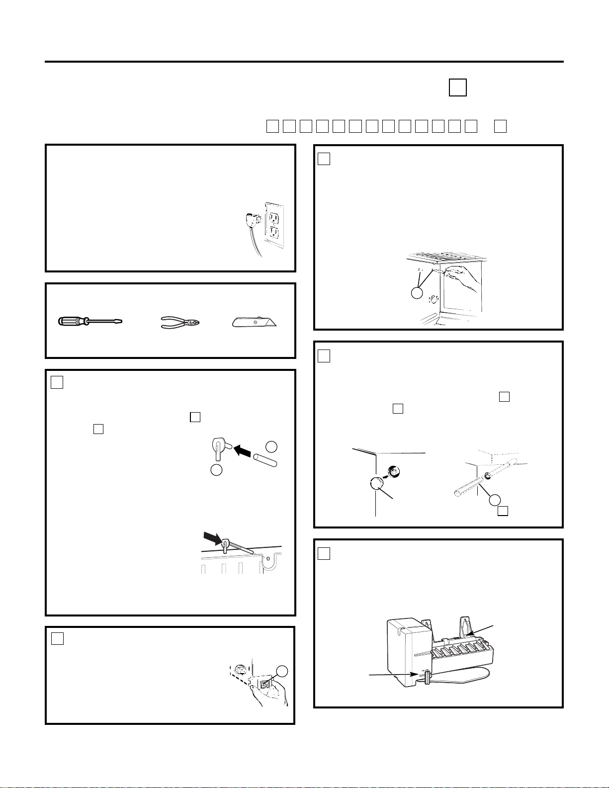
REMOVE PLUG COVER
Remove the electric plug cover from
the left side wall of the freezer by
pulling the cover (A) straight out
while pressing the sides of the cover
to free its tabs from the slots. Discard
the cover.
2
A
INSTALL WATER TUBE INLET
If the refrigerator already has a water tube inlet
on the back of the refrigerator, go to Step 2.
• Cut the fill tube (16) to the length (refer to
the template on page 66),
with a sharp knife or a singleedge razor blade.
• Slide the fill tube (16) onto
the water tube inlet (15).
• Find the small label in the
upper right hand corner on the back of the
refrigerator. Peel off the label.
• On the tube side of the
water tube inlet (15) there
is an adhesive backing.
Remove the adhesive
backing and slide the
tube into the hole near
the top at the back of the refrigerator.
Firmly press on the inlet to secure it.
G
G
B
15
16
Power
Switch
Hole for
wire tie
(Appearance may vary)
Page 20
19
PLUG IN THE ICEMAKER
Hold the icemaker in the freezer compartment as
shown. Insert the icemaker power cord plug (D)
into the socket, making sure the prongs and holes
are matched. If holes do not match, see Step 6.
Press the plug firmly into the socket.
8
Installation Instructions
MOUNT ICEMAKER
• Lift the icemaker so the fill tube extension (10)
fits in the fill cup opening (C). Hang the icemaker
on the two mounting screws (A).
Make sure:
• The power cord is still firmly in the socket.
• The fill tube extension (10) is still in the fill cup
opening. (Check the rear of the refrigerator to
make sure the fill tube has not been pushed out
of the back of the refrigerator.)
• The icemaker mounting screws are located in
the uppermost position of the mounting slots.
THEN TIGHTEN THE ICEMAKER MOUNTING SCREWS
SECURELY.
9
INSTALL THE ICEMAKER FILL CUP
Install the icemaker fill cup (side-mounted) (17) into
the icemaker as shown.
7
INSTALL THE ICE BUCKET
Put the ice bucket (11)
directly under the
icemaker (to the left and
all the way to the rear of
the shelf under the
icemaker).
Make sure the icemaker
power switch is set to
OFF.
10
11
ATTACH WARRANTY LABEL
A label (9) is provided with this kit to record the date
of installation for warranty purposes. Apply it to the
back of the refrigerator.
11
KEEP THIS MANUAL
The warranty for the icemaker is printed in this
manual. Keep this manual with your Refrigerator
Owner’s Manual.
The icemaker installation inside the freezer is now
complete. Continue to the Water Valve Assembly
section.
12
10
C
A
D
POWER CORD ADAPTER
(on some models)
There is a power cord adapter (18) included with
the kit. Visually inspect to see if the power cord on the
icemaker matches the socket on the side wall of the
freezer compartment. If needed, secure the adapter
to the side of the icemaker power cord. When
connecting the adapter to the power cord, make sure
the seal is in place between the connectors, and ensure
that both connector locks are snapped in place. Secure
the power cord adapter to the icemaker by putting it
into the hook at the back of the icemaker and attaching
it to the icemaker with a wire tie (20).
6
Hook
Seal
Locks
17
Page 21
20
Installation Instructions
REMOVE THE COVER
At the bottom rear of the refrigerator, remove the
screw(s) holding the compressor compartment cover
(if covered) and save for reinstallation later. Bend the
cover back for access to the compartment.
1
BEFORE YOU BEGIN
Read each step thoroughly before proceeding.
•
CAUTION –Unplug the
Refrigerator. To eliminate the danger
of electric shock during installation,
you must unplug the refrigerator
from its electrical outlet.
WATER VALVE ASSEMBLY INSTALLATION INSTRUCTIONS G
Are these the right instructions for your model? Follow the Installation Instructions indicated by
the label on the back of the refrigerator— or
TSRQPNMLKJHGFC
Flat blade and Phillips
screwdrivers
Pliers
TOOLS YOU WILL NEED
Sharp knife
1/4″ and 5/16″ Nutdrivers
ATTACH THE WATER VALVE
• Locate the female connector plug (B).
2
• Plug the female connector (B) onto the male
terminals on the water valve wire extension (19).
Either wire can go on either terminal.
• Plug the female connector on the water valve wire
extension (19) onto the male terminals on the
water valve (4). Either wire can go on either
terminal.
• Fasten the water valve to the
cabinet edge hole
using the hex-head screw (13)
from the kit
.
DO NOT DRILL ANY ADDITIONAL HOLES.
• Check the plastic water line nut on the bottom of the
water valve to be sure it is hand tight. DO NOT USE
TOOLS.
B
B
4
13
19
Page 22
CONNECT THE WATER LINE
• Squeeze the ends of the hose clamp (3) or (6) from
the kit with pliers and slide the clamp over the
water tube inlet. (Use the black clamp (3) with
the black fill tube inlet, use the other clamp (6)
with the other fill tube inlet.)
• While still squeezing the clamp, insert the
plastic water line into the inlet as far as it will
go (approximately 1″ [25 mm]).
• Then slide the clamp downward to capture the
plastic water line in place.
• Make sure the fill tube is aimed down.
Installation Instructions
INSTALL WATER LINE CLAMP
• Attach the metal water line clamp (strain relief)
(8) to the refrigerator. Drive the screw (7) from the
kit through the clamp (8) at the indent into the
back of the cabinet.
• The metal clamp is for the house water line (see
the Water Line Installation Instructions). It is not
to be used for the tubing from the water valve up
to the icemaker.
3
4
Water tube
inlet
ATTACH THE PLASTIC WATER LINE
Fasten the plastic water line to the back of the
cabinet with adhesive-backed fasteners (5),
spacing the fasteners as shown to take up the
slack in the line.
5
WATER VALVE INSTALLED
Refer to the Water Line Installation Instructions for
connection to the home water supply. After water
line installation is completed, set the icemaker
power switch to ON.
The icemaking cycle will not begin until the
icemaker and freezer compartment reach
operating temperature, then icemaking will
begin automatically.
6
7
8
3
6
or
21
Adhesive-backed fasteners
for plastic water line
5
Page 23
22
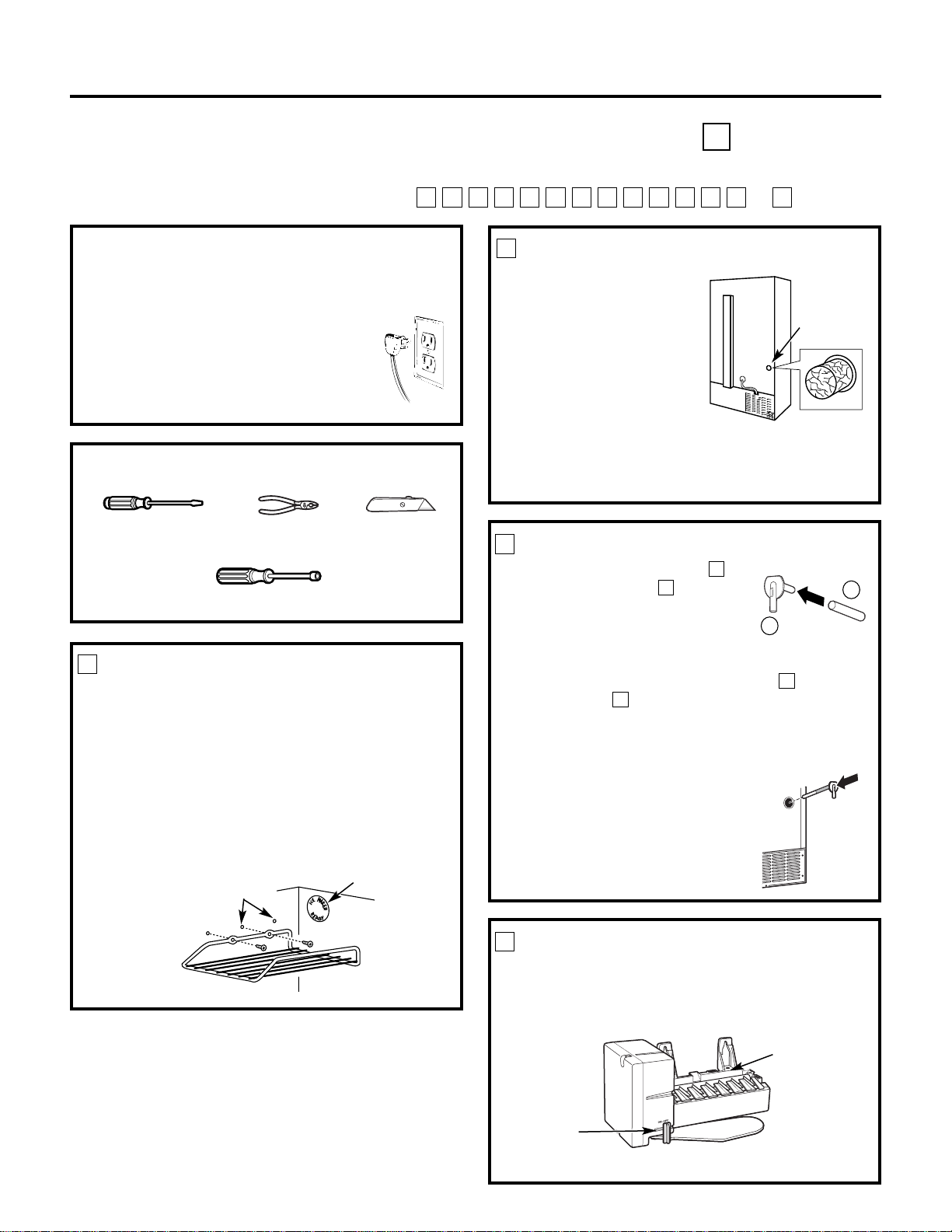
INSTALL WATER TUBE INLET
• Locate the hole in the upper right corner on the
back of the refrigerator and, using a knife, clear
the foil from the hole.
• Remove the gray insulation plug from the hole.
NOTE: It may be necessary to remove the screw
from the top right condenser mounting clip for
better access to the hole (see page 25, Step 4).
• Cut the fill tube (16) to the length (refer to the
template on page 66), with a sharp knife or a
single-edge razor blade.
• Slide the fill tube (16) onto
the water tube inlet (15).
• On the tube side of the water
tube inlet (15) there is an
adhesive backing. Remove
the backing. Slide the tube
into the hole on the back
of the refrigerator as
shown. Firmly press on
the inlet to secure it.
H
H
2
Installation Instructions
ICEMAKER INSTALLATION INSTRUCTIONS H
Are these the right instructions for your model? Follow the Installation Instructions indicated by
the label on the back of the refrigerator— or
TSRQPNMLKJHGFC
BEFORE YOU BEGIN
Read each step thoroughly before proceeding.
•
CAUTION –Unplug the
Refrigerator. To eliminate the danger
of electric shock during installation,
you must unplug the refrigerator
from its electrical outlet.
Flat blade and Phillips
screwdrivers
Pliers
TOOLS YOU WILL NEED
Sharp knife
PREPARE FOR INSTALLATION
• Remove and discard the white
plug from the upper left corner
of the freezer wall.
1
SET POWER SWITCH TO OFF
Set the icemaker power switch to OFF. Leave
the power switch in the OFF position until the
refrigerator is connected to the water supply to
prevent premature operation.
5
Remove
plug
REMOVE PLUG COVER
• Remove the electric plug cover
from the left side wall and discard it.
• Remove the screw and pull the
cover off.
3
LOOSEN MOUNTING SCREWS
Loosen the two mounting screws (A) but do not
screw them all the way out. The screws should
extend approximately 1/2″ (13 mm) out from
the freezer wall.
4
A
15
16
NOTE: If you have refrigerator model TNS22 or TNX22, please refer to the installation instructions
for , instead of using the instructions.
HP
Power
Switch
Hole for
wire tie
(Appearance may vary)
Page 24
23
Installation Instructions
PLUG IN THE ICEMAKER
Place the icemaker on its side as shown. Insert the
icemaker power cord plug (B) into the socket,
making sure the prongs and holes are matched.
If holes do not match, see Step 6. Press the plug
firmly into the socket.
8
MOUNT ICEMAKER
• Lift the icemaker so the fill tube (16) fits in the fill
cup opening (C). Hang the icemaker on the two
mounting screws (A).
Make sure:
• The power cord is still firmly in the socket.
• The fill tube (16) is still in the fill cup opening.
(Check the rear of the refrigerator to make sure
the fill tube has not been pushed out of the back
of the refrigerator.)
• The icemaker mounting screws are located in
the uppermost position of the mounting slots.
THEN TIGHTEN THE ICEMAKER MOUNTING SCREWS
SECURELY.
9
7
INSTALL THE ICE BUCKET
Put the ice bucket (11) in place under the icemaker.
Make sure the icemaker power switch is set to OFF.
10
11
ATTACH WARRANTY LABEL
A label (9) is provided with this kit to record the date
of installation for warranty purposes. Apply it to the
back of the refrigerator.
11
KEEP THIS MANUAL
The warranty for the icemaker is printed in this
manual. Keep this manual with your Refrigerator
Owner’s Manual.
The icemaker installation inside the freezer is now
complete. Continue to the Water Valve Assembly
section.
12
16
C
A
B
INSTALL THE ICEMAKER FILL CUP
Install the icemaker fill cup (side-mounted) (17) into
the icemaker as shown.
POWER CORD ADAPTER
(on some models)
There is a power cord adapter (18) included with
the kit. Visually inspect to see if the power cord on the
icemaker matches the socket on the side wall of the
freezer compartment. If needed, secure the adapter
to the side of the icemaker power cord. When
connecting the adapter to the power cord, make sure
the seal is in place between the connectors, and ensure
that both connector locks are snapped in place. Secure
the power cord adapter to the icemaker by putting it
into the hook at the back of the icemaker and attaching
it to the icemaker with a wire tie (20).
6
Hook
Seal
Locks
17
Page 25
24
INSTALL WATER LINE CLAMP
• Attach the metal water line clamp (strain relief)
(8) to the refrigerator. Drive the screw (7) from the
kit through the clamp (8) at the indent into the
back of the cabinet.
• The metal clamp is for the house water line (see
the Water Line Installation Instructions). It is not
to be used for the tubing from the water valve up
to the icemaker.
2
Installation Instructions
BEFORE YOU BEGIN
Read each step thoroughly before proceeding.
•
CAUTION –Unplug the
Refrigerator. To eliminate the danger
of electric shock during installation,
you must unplug the refrigerator
from its electrical outlet.
WATER VALVE ASSEMBLY INSTALLATION INSTRUCTIONS H
Are these the right instructions for your model? Follow the Installation Instructions indicated by
the label on the back of the refrigerator— or
TSRQPNMLKJHGFC
Flat blade and Phillips
screwdrivers
Pliers
TOOLS YOU WILL NEED
Sharp knife
1/4″ and 5/16″ Nutdriver
ATTACH THE WATER VALVE
• Locate the female connector plug (B).
1
13
• Plug the female connector (B) onto the male
terminals on the water valve (4). Either wire
can go on either terminal.
• Fasten the water valve to the
cabinet edge hole
using the hex-head screw (13) from the kit.
DO NOT DRILL ANY ADDITIONAL HOLES.
• Check the plastic water line nut on the bottom of
the water valve to be sure it is hand tight. DO NOT
USE TOOLS.
B
B
4
7
8
Page 26
Installation Instructions
ATTACH THE PLASTIC WATER LINE
Fasten the plastic water line to the back of the
cabinet with adhesive-backed fasteners (5), spacing
the fasteners as shown to take up the slack in the
line. (It may be necessary to remove the screw from
the top right condenser mounting clip for better
access to the water tube inlet).
4
Adhesive-backed fasteners
for plastic water line
WATER VALVE INSTALLED
Refer to the Water Line Installation Instructions for
connection to the home water supply. After water
line installation is completed, set the icemaker
power switch to ON.
The icemaking cycle will not begin until the
icemaker and freezer compartment reach
operating temperature, then icemaking will
begin automatically.
5
25
CONNECT THE WATER LINE
• Squeeze the ends of the hose clamp (3) from
the kit with pliers and slide the clamp over the
water tube inlet.
• While still squeezing the clamp, insert the
plastic water line into the inlet as far as it will
go (approximately 1″ [25 mm]).
• Then slide the clamp downward to capture the
plastic water line in place.
• Make sure the fill tube is aimed down.
• If the condenser mounting screw was removed,
secure the condenser to the refrigerator by
replacing the mounting clip and screw.
DO NOTOVER-TIGHTEN THE SCREW.
3
Water tube
inlet
3
Page 27
INSTALL FILL TUBE
• Cut the fill tube (16) to the
length (refer to the template
on page 66) with a sharp knife
or a single-edge razor blade.
• Slide the fill tube (16) onto the
water tube inlet (15).
• Cut the fill tube extension (10) to the length
(refer to the template on page 67) with a sharp
knife or a single-edge razor blade.
• Slide the fill tube extension (10) completely over
the fill tube on the water tube inlet (15).
• On the tube side of the water
tube inlet (15) there is an
adhesive backing. Remove the
backing and slide the tube into
the hole on the back of the
refrigerator as shown. Firmly
press on the inlet to secure it.
J
J
J
J
3
Installation Instructions
ICEMAKER INSTALLATION INSTRUCTIONS J
Are these the right instructions for your model? Follow the Installation Instructions indicated by
the label on the back of the refrigerator— or
TSRQPNMLKJHGFC
BEFORE YOU BEGIN
Read each step thoroughly before proceeding.
•
CAUTION –Unplug the
Refrigerator. To eliminate the danger
of electric shock during installation,
you must unplug the refrigerator
from its electrical outlet.
Flat blade and Phillips
screwdrivers
Pliers
TOOLS YOU WILL NEED
Sharp knife
26
REMOVE ICE CUBE TRAY SHELF
If your refrigerator has an installed ice cube tray
shelf, use a Phillips screwdriver to remove the two
screws. Remove the ice tray shelf. Install the screws
in the back two holes until the screw heads are
about 1/2″ (13 mm) from the side wall of the freezer.
If your refrigerator was not originally equipped with
an installed ice cube tray shelf, use the screws (14)
that are supplied in the kit.
Place the shelf, flat side up, in the lower basket with
the sloped end at the back.
1
PREPARE THE REFRIGERATOR
Find the sticker located
on the back of the
refrigerator about
midway up on the right
hand side. Remove the
sticker and clear away
any foil tape from the
opening. Also remove
the sticker from the top
left corner of the freezer
compartment.
Remove the gray insulation plug that fills the hole
through the cabinet.
2
SET POWER SWITCH TO OFF
Set the icemaker power switch to OFF. Leave
the power switch in the OFF position until the
refrigerator is connected to the water supply to
prevent premature operation.
4
Partially reinstall two
screws in rear two holes
Remove sticker
Remove
sticker
Remove
insulation plug
1/4″and 5/16″ Nutdriver or adjustable wrench
15
16
Power
Switch
Hole for
wire tie
(Appearance may vary)
d
o
m
l
o
u
r
s
o
d
l
s
o
p
m
i
i
r
u
t
s
s
a
m
i
m
p
t
e
i
r
a
e
o
m
m
t
L
e
e
r
o
t
L
Page 28
PLUG IN THE ICEMAKER
Place the icemaker on its
side as shown. Insert the
icemaker power cord plug
(A) into the socket on the
side wall, making sure the
prongs and holes are
matched. Press the plug
firmly into the socket.
8
Installation Instructions
MOUNT THE ICEMAKER
• Lift the icemaker so the fill tube extension (10) fits
in the fill cup opening (C). Hang the icemaker on
the two mounting screws (A).
Make sure:
• The power cord is still firmly in the socket.
• The fill tube extension (10) is still in the fill cup
opening. (Check the rear of the refrigerator to
make sure the fill tube has not been pushed out
of the back of the refrigerator.)
• The icemaker mounting screws are located in
the uppermost position of the mounting slots.
• Make sure the icemaker power switch is set
to OFF.
THEN TIGHTEN THE ICEMAKER MOUNTING
SCREWS SECURELY.
9
INSTALL THE ICEMAKER FILL CUP
Install the icemaker fill cup (side-mounted) (17) into
the icemaker as shown.
5
ATTACH WARRANTY LABEL
A label (9) is provided with this kit to record the date
of installation for warranty purposes. Apply it to the
back of the refrigerator.
11
KEEP THIS MANUAL
The warranty for the icemaker is printed in this
manual. Keep this manual with your Refrigerator
Owner’s Manual.
The icemaker installation inside the freezer is now
complete. Continue to the Water Valve Assembly
section.
12
10
C
A
A
REMOVE PLUG COVER
Remove the electric plug cover
from the side wall of the freezer
compartment. Insert a standard
screwdriver blade into the slot in
the cover and twist the screwdriver,
opening the slot. The cover will pop
off. Discard this cover.
6
INSTALL THE ICE BUCKET
Place the ice bucket that came with your refrigerator
in the lowest position on the left side of the freezer
compartment.
10
POWER CORD ADAPTER
(on some models)
There is a power cord adapter (18) included with
the kit. Visually inspect to see if the power cord on the
icemaker matches the socket on the side wall of the
freezer compartment. If needed, secure the adapter
to the side of the icemaker power cord. When
connecting the adapter to the power cord, make sure
the seal is in place between the connectors, and ensure
that both connector locks are snapped in place. Secure
the power cord adapter to the icemaker by putting it
into the hook at the back of the icemaker and attaching
it to the icemaker with a wire tie (20).
7
Hook
Seal
Locks
27
17
Page 29
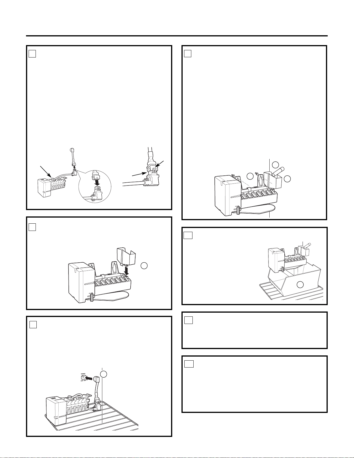
• Fasten the water valve to the cabinet by driving
the hex-head screw (13).
DO NOT DRILL ANY ADDITIONALHOLES
NOTE: There may be some internal refrigerant
tubing that will need to be moved slightly in order
to provide enough room to install the water valve.
• Check the plastic water line nut on the bottom
of the water valve to be sure it is hand tight.
DO NOT USE TOOLS.
28
Installation Instructions
REMOVE THE ACCESS COVER
Remove the rear access cover. This requires
removing six screws which attach the cover to the
back of the refrigerator case. Use a 5/16″ socket or
an adjustable wrench. Be sure to save the screws as
the access cover must be reinstalled later to ensure
your refrigerator will function properly.
1
BEFORE YOU BEGIN
Read each step thoroughly before proceeding.
•
CAUTION –Unplug the
Refrigerator. To eliminate the danger of
electric shock during installation, you
must unplug the refrigerator from its
electrical outlet.
WATER VALVE ASSEMBLY INSTALLATION INSTRUCTIONS J
Are these the right instructions for your model? Follow the Installation Instructions indicated by
the label on the back of the refrigerator— or
TSRQPNMLKJHGFC
Flat blade and Phillips
screwdrivers
Pliers
TOOLS YOU WILL NEED
Sharp knife
1/4″ Nutdriver
ATTACH THE WATER VALVE
• Locate the female connector plug (A).
2
• Plug the female connector (A) onto the male
terminals on the water valve (4). Either wire
can go on either terminal.
A
A
4
13
5/16″ Socket or adjustable wrench
Page 30
Installation Instructions
ATTACH THE PLASTIC WATER LINE
Route the plastic water line along the back of the
refrigerator to the icemaker hole in the case back.
Use three of the adhesive-backed fasteners (5) to
secure the tube to the case back.
5
WATER VALVE INSTALLED
Refer to the Water Line Installation Instructions for
connection to the home water supply. After water
line installation is completed, set the icemaker
power switch to ON.
The icemaking cycle will not begin until the
icemaker and freezer compartment reach
operating temperature, then icemaking will
begin automatically.
6
Adhesive-backed
fasteners for
plastic water line
29
INSTALL WATER LINE CLAMP
• Push the metal water line clamp (strain relief) (12)
onto the lower flange of the cabinet back, directly in
line with the water valve.
• The metal clamp is for the house water line. (See
the Water Line Installation Instructions). It is not
to be used for the tubing from the water valve up
to the icemaker.
3
12
CONNECT THE WATER LINE
• Ensure that you have sufficient length of plastic
tube to extend well into the water tube inlet.
Cut off excess tubing.
• Squeeze the ends of the hose clamp (3) from
the kit with pliers and slide the clamp over the
water tube inlet.
• While still squeezing the clamp, insert the
plastic water line into the inlet as far as it will
go (approximately 1″ [25 mm]).
• Then slide the clamp downward to capture the
plastic water line in place.
• Make sure the fill tube is aimed down.
4
Water tube
inlet
3
5
Page 31

INSTALL FILL TUBE
• Slide the insulated fill tube (21)
onto the water tube inlet (15),
making sure that the open side
of the fill tube faces up.
• Go to the back of the
refrigerator. On the tube side
of the water tube inlet (15) there is an adhesive
backing. Remove the adhesive backing and slide the
tube into the hole near the top at the back of the
refrigerator. Firmly press on the inlet to secure it to
the refrigerator.
1
3
Installation Instructions
ICEMAKER INSTALLATION INSTRUCTIONS K
Are these the right instructions for your model? Follow the Installation Instructions indicated by
the label on the back of the refrigerator— or
TSRQPNMLKJHGFC
BEFORE YOU BEGIN
Read each step thoroughly before proceeding.
•
CAUTION –Unplug the
Refrigerator. To eliminate the danger
of electric shock during installation,
you must unplug the refrigerator
from its electrical outlet.
Flat blade and Phillips
screwdrivers
Pliers
TOOLS YOU WILL NEED
Sharp knife
SET POWER SWITCH TO OFF
Set the icemaker power switch to OFF. Leave
the power switch in the OFF position until the
refrigerator is connected to the water supply to
prevent premature operation.
5
INSTALL MOUNTING BRACKET
• Remove the three small plug buttons on the rear
wall of the freezer and replace them with three
screws (27) supplied with the icemaker kit. Do
not screw them all the way in. The screws should
extend approximately 1/4″ (6 mm) out from
the freezer wall.
• Install the icemaker
bracket (26) by hanging
it from the three screws
that were just installed.
Tighten the three screws
securely.
4
Remove
plug
15
21
PREPARE FOR INSTALLATION
• Remove the
upper
outlet cover with a flat-blade
screwdriver.
• If there is already an icemaker bracket (26) installed in
the freezer, remove the two screws holding on the cover.
Remove and discard the cover. Go to Step 5.
2
REMOVE FILL HOLE PLUG
• Remove and discard the large white plug from the
rear freezer wall. Pull out the gray insulation plug
and remove any debris.
Cover
30
Power
Switch
Hole for
wire tie
(Appearance may vary)
Page 32

31
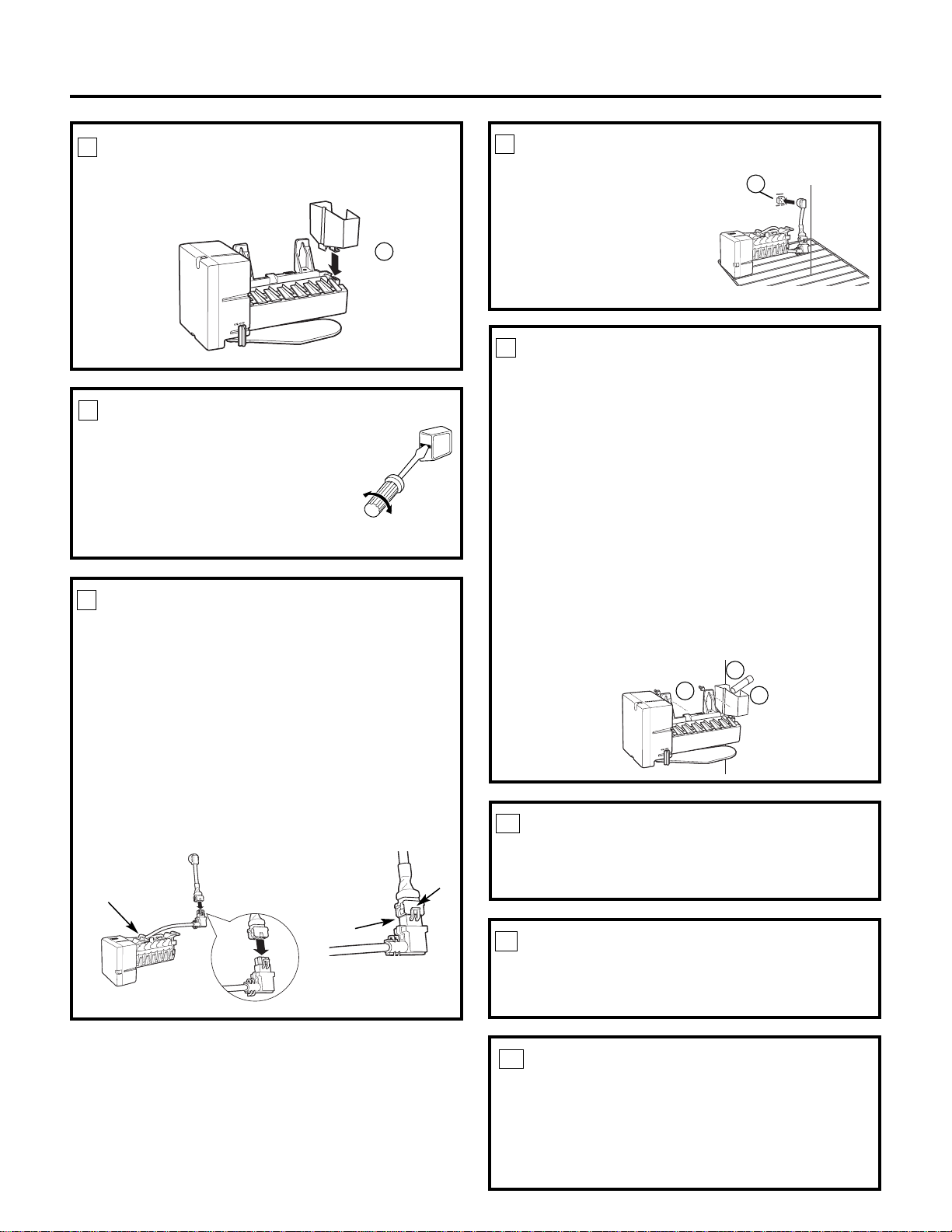
INSTALL THE ICEMAKER FILL CUP
AND INSERT
Install the icemaker fill cup (center-mounted) (23) and
icemaker insert (24) into the icemaker as shown.
23
MOUNT THE ICEMAKER
• Lift the icemaker up and hang it on the icemaker
bracket (26). Make sure the insulated fill tube (21)
goes into the fill cup (23) opening. To secure the
icemaker to the bracket (26), use two screws (22)
and install as shown.
Make sure:
• The power cord is still firmly in the socket.
• The insulated fill tube (21) extends into the fill cup
opening at the back of the icemaker. (Check the
rear of the refrigerator to make sure that the fill
tube has not
pushed out the
back of the
refrigerator).
• The icemaker
is secured to
the bracket.
8
6
PLUG IN THE ICEMAKER
Holding the icemaker in place, insert the power
cord plug into the socket, making sure that the prongs
and holes are matched. Press the plug firmly into the
socket. Lock the plug in place by clipping the restraints
onto each side of the plug. Make sure the restraints
click into place.
7
INSTALL THE ICE BUCKET
Place the ice bucket (11) under the icemaker.
Make sure the icemaker power switch is set to OFF.
9
11
ATTACH WARRANTY LABEL
A label (9) is provided with this kit to record the date
of installation for warranty purposes. Apply it to the
back of the refrigerator.
10
KEEP THIS MANUAL
The warranty for the icemaker is printed in this
manual. Keep this manual with your Refrigerator
Owner’s Manual.
The icemaker installation inside the freezer is now
complete. Continue to the Installing the Water Valve
Assembly section.
11
24
21
23
26
22
Installation Instructions
Page 33

Installation Instructions
REMOVE THE COVER
Use a nutdriver or an adjustable wrench to remove
the compressor compartment access cover. This
requires removing six screws which attach the cover
to the back of the refrigerator case.
Be sure to save the screws as the access cover
must be reinstalled later to ensure your refrigerator
will function properly.
1
BEFORE YOU BEGIN
Read each step thoroughly before proceeding.
•
CAUTION –Unplug the
Refrigerator. To eliminate the danger
of electric shock during installation,
you must unplug the refrigerator
from its electrical outlet.
WATER VALVE ASSEMBLY INSTALLATION INSTRUCTIONS K
Are these the right instructions for your model? Follow the Installation Instructions indicated by
the label on the back of the refrigerator— or
TSRQPNMLKJHGFC
Flat blade and Phillips
screwdrivers
Pliers
TOOLS YOU WILL NEED
Sharp knife
1/4″ and 5/16″ Nutdrivers, or adjustable wrench
ATTACH THE WATER VALVE
• Visually inspect your
model. It may be a 3-pin
or a 2-pin model.
• Locate the 3-pin male
connector plug (C). Plug
the water valve wire
adapter (25) onto the
male connector plug, then plug it onto the male
terminals on the water valve (4). Either wire can
go on either water valve terminal.
• Locate the red 2-pin
female connector plug
(A). Plug the red female
connector (A) onto the
red male terminal.
Locate the white female
connector (B). Plug the
white female connector (B) onto the blue male
water valve terminal.
2
• Fasten the water valve to the cabinet using the
hex-head screw (13) from the kit.
13
C
4
INSTALL WATER LINE CLAMP
• Attach the water line clamp (strain relief) (8) to the
refrigerator. Drive the screw (7) from the kit through
the clamp (8) and into the small hole at the back of
the cabinet.
• The water line clamp is for the house water line (see
the Water Line Installation Instructions). It is not to
be used for the tubing from the water valve up to
the icemaker.
3
8
25
A
B
8
7
32
3-pin models
2-pin models
Page 34

33
Installation Instructions
ROUTE AND ATTACH THE PLASTIC
WATER LINE
• Route the plastic water line along the back of the
refrigerator to the water tube inlet.
• Use the three adhesive backed fasteners (5) to
secure the plastic water line to the case back.
5
4
CONNECT THE WATER LINE
• Make sure there is enough plastic water line to
extend from the water valve to well into the water
tube inlet (15). Cut off any excess tubing.
• Squeeze the ends of the hose clamp (3) or (6) from
the kit with pliers and slide the clamp over the water
tube inlet. (Use the black clamp (3) with the black
water tube inlet, use the other clamp (6) with the
other water tube inlet.)
• While still squeezing the clamp, insert the
plastic water line into the inlet as far as it will
go (approximately 1″ [25 mm]).
• Then slide the clamp downward to capture the
plastic water line in place.
• Make sure the fill tube is aimed down.
3
Water tube
inlet
WATER VALVE INSTALLED
Refer to the Water Line Installation Instructions for
connection to the home water supply. After water
line installation is completed, set the icemaker
power switch to ON.
The icemaking cycle will not begin until the
icemaker and freezer compartment reach
operating temperature, then icemaking will
begin automatically.
6
Adhesive-backed fasteners
for plastic water line
6
or
Page 35

34
2
Installation Instructions
ICEMAKER INSTALLATION INSTRUCTIONS L
Are these the right instructions for your model? Follow the Installation Instructions indicated by
the label on the back of the refrigerator— or
TSRQPNMLKJHGFC
BEFORE YOU BEGIN
Read each step thoroughly before proceeding.
•
CAUTION –Unplug the
Refrigerator. To eliminate the danger
of electric shock during installation,
you must unplug the refrigerator
from its electrical outlet.
Flat blade and Phillips
screwdrivers
Pliers
TOOLS YOU WILL NEED
Sharp knife
SET POWER SWITCH TO OFF
Set the icemaker power switch to OFF. Leave
the power switch in the OFF position until the
refrigerator is connected to the water supply to
prevent premature operation.
4
1
REMOVE ICE CUBE TRAY SHELF
• Remove the two screws securing the ice cube tray
to the side wall of the freezer. Remove the tray.
• Replace the screws but do not screw them all the
way in. The screw heads should extend about
1/2″ (13 mm) from the side wall of the freezer.
1/4″ Nutdriver or adjustable wrench
Remove
plug
INSTALL FILL TUBE EXTENSION
• Cut the fill tube extension (10)
to the length (refer to the
template on page 67) with
a sharp knife or a single-edge
razor blade and slide it onto
the fill tube against the stop.
L
L
3
PREPARE FOR INSTALLATION
• Remove and discard the large white plug from
the rear freezer wall.
• Remove the outlet cover with a flat-blade
screwdriver.
L
10
Power
Switch
Hole for
wire tie
(Appearance may vary)
Page 36

INSTALL THE ICE BUCKET
Put the ice bucket in place
under the icemaker.
Make sure the icemaker
power switch is set to
OFF.
Installation Instructions
INSTALL THE ICEMAKER FILL CUP
Install the icemaker fill cup (side-mounted) (17) into the
icemaker as shown.
5
PLUG IN THE ICEMAKER
Holding the icemaker in place, insert the power
cord plug into the socket, making sure that the prongs
and holes are matched. Press the plug firmly into the
socket. Lock the plug in place by clipping the restraints
onto each side of the plug. Make sure the restraints
click into place.
6
ATTACH WARRANTY LABEL
A label (9) is provided with this kit to record the date
of installation for warranty purposes. Apply it to the
back of the refrigerator.
9
KEEP THIS MANUAL
The warranty for the icemaker is printed in this
manual. Keep this manual with your Refrigerator
Owner’s Manual.
The icemaker installation inside the freezer is now
complete. Continue to the Water Valve Assembly
section.
10
MOUNT THE ICEMAKER
• Lift the icemaker so the fill tube extension (10)
fits in the fill cup opening (C). Hang the icemaker
on the two mounting screws (A).
Make sure:
• The power cord is still firmly in the socket.
• The fill tube extension (10) is still in the fill cup
opening. (Check the rear of the refrigerator to
make sure the fill tube has not been pushed out
of the back of the refrigerator.)
• The icemaker mounting screws are located in
the uppermost position of the mounting slots.
THEN TIGHTEN THE ICEMAKER MOUNTING
SCREWS SECURELY.
7
10
C
A
8
351736
Page 37

Installation Instructions
REMOVE THE COVER
At the bottom rear of the refrigerator, remove the
screw(s) holding the access cover.
Bend the cover back for access to the compartment.
Be sure to save the screws as the access cover must
be reinstalled later to ensure your refrigerator will
function properly.
1
BEFORE YOU BEGIN
Read each step thoroughly before proceeding.
•
CAUTION –Unplug the
Refrigerator. To eliminate the danger
of electric shock during installation,
you must unplug the refrigerator
from its electrical outlet.
WATER VALVE ASSEMBLY INSTALLATION INSTRUCTIONS L
Are these the right instructions for your model? Follow the Installation Instructions indicated by
the label on the back of the refrigerator— or
TSRQPNMLKJHGFC
Flat blade and Phillips
screwdrivers
Pliers
TOOLS YOU WILL NEED
Sharp knife
1/4″ and 5/16″ Nutdrivers
• Fasten the water valve to the
cabinet by driving the
hex-head screw (13) from the kit into the hole
in the cabinet leg.
ATTACH THE WATER VALVE
• Locate the female connector plug (C) which is
attached to the cabinet by a metal or plastic clip.
Remove the clip by removing the screw.
2
• Plug the female connector (C) onto the male
terminals on the water valve (4). Either wire
can go on either terminal.
Metal or
plastic clip
C
C
4
13
Page 38

Installation Instructions
ROUTE AND ATTACH THE PLASTIC
WATER LINE
• Route the plastic water line along the back of the
refrigerator to the water tube inlet.
• Use the three adhesive backed fasteners (5) to
secure the plastic water line to the case back.
5
WATER VALVE INSTALLED
Refer to the Water Line Installation Instructions for
connection to the home water supply. After water
line installation is completed, set the icemaker
power switch to ON.
The icemaking cycle will not begin until the
icemaker and freezer compartment reach
operating temperature, then icemaking will
begin automatically.
6
Adhesive-backed
fasteners for
plastic water line
37
4
CONNECT THE WATER LINE
• Remove the small plastic cap (B) from the bottom of
the water tube inlet located in the upper-right rear
corner of the refrigerator.
• Squeeze the ends of the hose clamp (6) from the
kit with pliers and slide the clamp over the water
tube inlet.
• While still squeezing the clamp, insert the
plastic water line into the inlet as far as it will
go (approximately 1″ [25 mm]).
• Then slide the clamp downward to capture the
plastic water line in place.
• Make sure the fill tube is aimed down.
6
Water tube
inlet
B
INSTALL WATER LINE CLAMP
• Attach the metal water line clamp (strain relief)
(8) to the refrigerator. Drive one of the screws,
removed in Step 1, into the cabinet edge through
the clamp and hole in compressor cover.
• The metal clamp is for the house water line (see
Water Line Installation Instructions). It is not to be
used for the tubing from the water valve up to the
icemaker.
3
8
Screw
Page 39

38
PREPARE FOR INSTALLATION
Inside the freezer, loosen the two mounting screws
(B) but do not screw them all the way out. If your
model does not have the screws already in the
freezer wall, look for two plug buttons. Remove the
plug buttons and insert the two Phillips head screws
(14). The screws should extend approximately
1/2″ (13mm) out from the freezer wall.
3
Installation Instructions
ICEMAKER INSTALLATION INSTRUCTIONS M
Are these the right instructions for your model? Follow the Installation Instructions indicated by
the label on the back of the refrigerator— or
TSRQPNMLKJHGFC
BEFORE YOU BEGIN
Read each step thoroughly before proceeding.
•
CAUTION –Unplug the
Refrigerator. To eliminate the danger
of electric shock during installation,
you must unplug the refrigerator
from its electrical outlet.
Flat blade and Phillips
screwdrivers
Pliers
TOOLS YOU WILL NEED
Sharp knife
REMOVE THE OUTLET COVER
• Remove the outlet cover
with a flat-blade screwdriver.
2
B
SET POWER SWITCH TO OFF
Set the icemaker power switch to OFF. Leave
the power switch in the OFF position until the
refrigerator is connected to the water supply to
prevent premature operation.
5
INSTALL FILL TUBE
• If the refrigerator already
has a water tube inlet on
the back of the refrigerator,
go to Step 2.
• Cut the fill tube (16) to the
length (refer to the
template on page 66)
with a sharp knife or
a single-edge razor blade.
• Slide the fill tube (16) onto
the water tube inlet (15).
• Go to the back of the refrigerator. Find the small label
in the upper right hand corner and peel it off. On the
tube side of the water tube inlet (15) there is an
adhesive backing. Remove the adhesive backing and
slide the tube into the hole near the top at the back
of the refrigerator. Firmly press on the inlet to secure
it to the refrigerator.
M
M
1
15
16
INSTALL FILL TUBE EXTENSION
• Remove and discard the white plug from the
upper left corner of the freezer wall.
• Cut the fill tube extension (10) to the length
(refer to the template on page 67) with a sharp
knife or a single-edge razor blade and slide it onto
the fill tube against the stop.
M
M
4
Remove
plug
M
10
Power
Switch
Hole for
wire tie
(Appearance may vary)
Page 40

39
Installation Instructions
8
10
PLUG IN THE ICEMAKER
Holding the icemaker in place, insert the icemaker
power cord plug into the socket on the side wall,
making sure the prongs and holes are matched. Press
the plug firmly into the socket. Lock the plug in place
by clipping the restraints onto each side of the plug.
Make sure the restraints click into place.
7
INSTALL THE ICE BUCKET
Place the ice bucket (11) under the icemaker.
Make sure the icemaker power switch is in the
OFF position.
9
11
ATTACH WARRANTY LABEL
A label (9) is provided with this kit to record the date
of installation for warranty purposes. Apply it to the
back of the refrigerator.
10
KEEP THIS MANUAL
The warranty for the icemaker is printed in this
manual. Keep this manual with your Refrigerator
Owner’s Manual.
The icemaker installation inside the freezer is now
complete. Continue to the Water Valve Assembly
section.
11
INSTALL THE ICEMAKER FILL CUP
Install the icemaker fill cup (side-mounted) (17) into
the icemaker as shown.
6
D
MOUNT THE ICEMAKER
• Lift the icemaker so the fill tube extension (10) fits
in the fill cup opening (D). Hang the icemaker on
the two screws.
Make sure:
• The power cord is still firmly in the socket.
• The fill tube extension (10) extends into the fill
cup opening at the back of the icemaker. (Check
the rear of the refrigerator to make sure the fill
tube has not been pushed out of the back of the
refrigerator).
• The icemaker mounting screws are located in the
uppermost position of the mounting slots.
THEN SECURELY TIGHTEN THE ICEMAKER
MOUNTING SCREWS.
17
Page 41

40
Installation Instructions
BEFORE YOU BEGIN
Read each step thoroughly before proceeding.
•
CAUTION –Unplug the
Refrigerator. To eliminate the danger
of electric shock during installation,
you must unplug the refrigerator
from its electrical outlet.
WATER VALVE ASSEMBLY INSTALLATION INSTRUCTIONS M
Are these the right instructions for your model? Follow the Installation Instructions indicated by
the label on the back of the refrigerator— or
TSRQPNMLKJHGFC
Flat blade and Phillips
screwdrivers
Pliers
TOOLS YOU WILL NEED
Sharp knife
1/4″ and 5/16″ Nutdrivers
ATTACH THE WATER VALVE
• Locate the female connector plug. Plug the
female connector (C) onto the male terminals
on the water valve (4). Either wire can go on
either terminal.
2
13
• Fasten the water valve to the cabinet by driving
the hex-head screw (13) from the kit into the hole
in the cabinet leg.
C
4
REMOVE THE COVER
Use a 5/16″ nutdriver or an adjustable wrench to
remove the compressor compartment access cover.
This requires removing six screws which attach the
cover to the back of the refrigerator case.
Be sure to save the screws as the access cover
must be reinstalled later to ensure your refrigerator
will function properly.
1
Page 42

Installation Instructions
ROUTE AND ATTACH THE PLASTIC
WATER LINE
• Fasten the plastic water line to the back of the
cabinet with adhesive-backed fasteners (5),
spacing the fasteners as shown to take up slack
in the line.
5
WATER VALVE INSTALLED
Refer to the Water Line Installation Instructions for
connection to the home water supply. After water
line installation is completed, set the icemaker
power switch to ON.
The icemaking cycle will not begin until the
icemaker and freezer compartment reach
operating temperature, then icemaking will
begin automatically.
6
Adhesive-backed fasteners
for plastic water line
41
4
CONNECT THE WATER LINE
• Make sure there is enough plastic water line to
extend from the water valve to well into the
water tube inlet (15). Cut off any excess tubing.
• Squeeze the ends of the hose clamp (3) from the
kit with pliers and slide the clamp over the water
tube inlet.
• While still squeezing the clamp, insert the plastic
water line into the inlet as far as it will go
(approximately 1″ [25 mm]).
• Then slide the clamp downward to capture the
plastic water line in place.
• Make sure the fill tube is aimed down.
3
Water tube
inlet
INSTALL WATER LINE CLAMP
• Attach the metal water line clamp (strain relief)
(8) to the refrigerator. Drive the screw (7) from the
kit through the clamp (8) at the indent into the
back of the cabinet.
• The metal clamp is for the house water line (see
the Water Line Installation Instructions). It is not
to be used for the tubing from the water valve up
to the icemaker.
3
7
8
Page 43

REMOVE ICE CUBE TRAY SHELF
• Remove the two screws securing the ice cube tray
to the side wall of the freezer. Remove the tray.
• There are two white plug buttons above the screw
holes. Remove these plug buttons and install them
in the two screw holes that were used to hold the
ice cube tray shelf.
• Install two Phillips head screws (14) in the holes
that the plug buttons were in, but do not screw
them all the way in. The screw heads should
extend about 1/2″ (13 mm) from the side wall
of the freezer.
42
Installation Instructions
ICEMAKER INSTALLATION INSTRUCTIONS N
Are these the right instructions for your model? Follow the Installation Instructions indicated by
the label on the back of the refrigerator— or
TSRQPNMLKJHGFC
BEFORE YOU BEGIN
Read each step thoroughly before proceeding.
•
CAUTION –Unplug the
Refrigerator. To eliminate the danger
of electric shock during installation,
you must unplug the refrigerator
from its electrical outlet.
Flat blade and Phillips
screwdrivers
Pliers
TOOLS YOU WILL NEED
Sharp knife
2
PREPARE FOR INSTALLATION
• Remove and discard the large white plug from the
rear freezer wall. Pull out the gray insulation plug
and remove any debris.
• Remove the outlet cover with a flat-blade
screwdriver.
1
SET POWER SWITCH TO OFF
Set the icemaker power switch to OFF. Leave
the power switch in the OFF position until the
refrigerator is connected to the water supply to
prevent premature operation.
4
Plug
Buttons
14
INSTALL FILL TUBE
• Cut the fill tube with foil (16) to the length
(refer to the template on page 66) with a sharp
knife or a single-edge razor blade.
• Slide the fill tube with foil (16)
onto the water tube inlet (15).
• Go to the back of the refrigerator.
On the tube side of the water
tube inlet (15) there is an
adhesive backing. Remove the
adhesive backing and slide the
tube into the hole near the top
at the back of the refrigerator.
Firmly press on the inlet to
secure it to the refrigerator.
N
N
3
15
16
Power
Switch
Hole for
wire tie
(Appearance may vary)
Page 44

43
Installation Instructions
INSTALL THE ICEMAKER
FILL CUP
Install the icemaker fill cup (side-mounted) (17) into the
icemaker as shown.
5
PLUG IN THE ICEMAKER
Holding the icemaker in place, insert the icemaker
power cord plug (D) into the socket on the rear wall,
making sure the prongs and holes are matched. Press
the plug firmly into the socket. Lock the plug in place
by clipping the restraints onto each side of the plug.
Make sure the restraints click into place.
6
D
MOUNT THE ICEMAKER
• Lift the icemaker so the fill tube (16) goes into the
fill cup opening (17). Hang the icemaker on the
two screws (14).
Make sure:
• The power cord is still firmly in the socket.
• The fill tube (16) extends into the fill cup opening
at the back of the icemaker. (Check the rear of
the refrigerator to make sure the fill tube has not
been pushed out of the back of the refrigerator).
THEN SECURELY TIGHTEN THE ICEMAKER
MOUNTING SCREW.
7
16
17
INSTALL THE ICE BUCKET
Place the ice bucket (11) under the icemaker.
Make sure the icemaker power switch is set to OFF.
8
11
ATTACH WARRANTY LABEL
A label (9) is provided with this kit to record the date
of installation for warranty purposes. Apply it to the
back of the refrigerator.
9
KEEP THIS MANUAL
The warranty for the icemaker is printed in this
manual. Keep this manual with your Refrigerator
Owner’s Manual.
The icemaker installation inside the freezer is now
complete. Continue to the Water Valve Assembly
section.
10
17
Page 45

44
Installation Instructions
BEFORE YOU BEGIN
Read each step thoroughly before proceeding.
•
CAUTION –Unplug the
Refrigerator. To eliminate the danger
of electric shock during installation,
you must unplug the refrigerator
from its electrical outlet.
WATER VALVE ASSEMBLY INSTALLATION INSTRUCTIONS N
Are these the right instructions for your model? Follow the Installation Instructions indicated by
the label on the back of the refrigerator— or
TSRQPNMLKJHGFC
Flat blade and Phillips
screwdrivers
Pliers
TOOLS YOU WILL NEED
Sharp knife
1/4″ and 5/16″ Nutdrivers
ATTACH THE WATER VALVE
• Locate the female connector plug. Plug the
female connector (C) onto the male terminals
on the water valve (4). Either wire can go on
either terminal.
2
13
• Fasten the water valve to the cabinet by driving
the hex-head screw (13) from the kit into the hole
in the cabinet leg.
C
4
REMOVE THE COVER
Use a 5/16″ nutdriver or an adjustable wrench to
remove the compressor compartment access cover.
This requires removing six screws which attach the
cover to the back of the refrigerator case.
Be sure to save the screws as the access cover
must be reinstalled later to ensure your refrigerator
will function properly.
1
INSTALL WATER LINE CLAMP
• Attach the water line clamp (strain relief) (8) from
the kit to the refrigerator. With the clamp directly
in line with the water valve, drive the screw (7)
from the kit through the clamp (8) at the indent
into the back of the cabinet.
• The metal clamp is for the house water line (see
Water Line Installation Instructions). It is not to be
used for the tubing from the water valve up to the
icemaker.
3
7
8
Page 46

Installation Instructions
WATER VALVE INSTALLED
Refer to the Water Line Installation Instructions for
connection to the home water supply. After water
line installation is completed, set the icemaker
power switch to ON.
The icemaking cycle will not begin until the
icemaker and freezer compartment reach
operating temperature, then icemaking will
begin automatically.
6
45
ROUTE AND ATTACH THE PLASTIC
WATER LINE
• Fasten the plastic water line to the back of the
cabinet with adhesive-backed fasteners (5),
spacing the fasteners as shown to take up slack
in the line.
5
Adhesive-backed fasteners
for plastic water line
4
CONNECT THE WATER LINE
• Make sure there is enough plastic water line to
extend from the water valve to well into the
water tube inlet (15). Cut off any excess tubing.
• Squeeze the ends of the hose clamp (3) from the
kit with pliers and slide the clamp over the water
tube inlet.
• While still squeezing the clamp, insert the plastic
water line into the inlet as far as it will go
(approximately 1″ [25 mm]).
• Then slide the clamp downward to capture the
plastic water line in place.
• Make sure the fill tube is aimed down.
3
Water tube
inlet
Page 47

46
Installation Instructions
ICEMAKER INSTALLATION INSTRUCTIONS P
Are these the right instructions for your model? Follow the Installation Instructions indicated by
the label on the back of the refrigerator— or
TSRQPNMLKJHGFC
BEFORE YOU BEGIN
Read each step thoroughly before proceeding.
•
CAUTION –Unplug the
Refrigerator. To eliminate the danger
of electric shock during installation,
you must unplug the refrigerator
from its electrical outlet.
Flat blade and Phillips
screwdrivers
Pliers
TOOLS YOU WILL NEED
Sharp knife
1
PREPARE FOR INSTALLATION
• Remove and discard the large white plug from
the rear freezer wall. Pull out the gray insulation
plug and remove any debris.
• Remove the two small white plug buttons on the side
wall. Install two Phillips head screws (14) in the holes
that the plug buttons were in, but do not screw them
all the way in. The screw heads should extend about
1/2″ (13 mm) from the side wall of the freezer.
• Remove the outlet cover with a flat-blade
screwdriver.
SET POWER SWITCH TO OFF
Set the icemaker power switch to OFF. Leave
the power switch in the OFF position until the
refrigerator is connected to the water supply to
prevent premature operation.
3
14
INSTALL FILL TUBE
• Cut the fill tube (16) to the
length (refer to the template
on page 66) with a sharp knife
or a single-edge razor blade.
• Slide the fill tube (16) onto the
water tube inlet (15).
• Go to the back of the refrigerator. In the upper right
hand corner, remove the label covering the hole. Pull
out the insulation plug and any debris.
• On the tube side of the
water tube inlet (15) there
is an adhesive backing.
Remove the adhesive
backing and slide the
tube into the hole near
the top at the back of the refrigerator. Firmly press
on the inlet to secure it to the refrigerator.
P
P
2
15
16
Power
Switch
Hole for
wire tie
(Appearance may vary)
Page 48

47
Installation Instructions
INSTALL THE ICEMAKER FILL CUP
Install the icemaker fill cup (side-mounted) (17) into the
icemaker as shown.
5
MOUNT THE ICEMAKER
• Lift the icemaker so the fill tube (16) fits in the fill
cup opening (E). Hang the icemaker on the two
mounting screws (C).
Make sure:
• The power cord is still firmly in the socket.
• The fill tube (16) extends into the fill cup opening
on the back of the icemaker. (Check the rear of
the refrigerator to make sure the fill tube has not
been pushed out of the back of the refrigerator).
THEN SECURELY TIGHTEN THE ICEMAKER
MOUNTING SCREWS.
7
16
E
C
PLUG IN THE ICEMAKER
Holding the icemaker in
place, insert the icemaker
power cord plug (D) into
the socket on the rear
wall, making sure the
prongs and holes are
matched. If holes do not
match, see Step 4. Press
the plug firmly into the
socket.
6
D
INSTALL THE ICE BUCKET
Install the freezer shelf in the lowest position. Place
the ice bucket (11) on the shelf under the icemaker.
Make sure the icemaker power switch is set to OFF.
8
11
ATTACH WARRANTY LABEL
A label (9) is provided with this kit to record the date
of installation for warranty purposes. Apply it to the
back of the refrigerator.
9
KEEP THIS MANUAL
The warranty for the icemaker is printed in this
manual. Keep this manual with your Refrigerator
Owner’s Manual.
The icemaker installation inside the freezer is now
complete. Continue to the Water Valve Assembly
section.
10
POWER CORD ADAPTER
(on some models)
There is a power cord adapter (18) included with
the kit. Visually inspect to see if the power cord on the
icemaker matches the socket on the rear wall of the
freezer compartment. If needed, secure the adapter
to the side of the icemaker power cord. When
connecting the adapter to the power cord, make sure
the seal is in place between the connectors, and ensure
that both connector locks are snapped in place. Secure
the power cord adapter to the icemaker by putting it
into the hook at the back of the icemaker and attaching
it to the icemaker with a wire tie (20).
4
Hook
Seal
Locks
17
Page 49

48
Installation Instructions
REMOVE THE COVER
Remove the screws holding the left side of the
compressor cover and save them for reinstallation
later. Bend the cover back to access the
compartment.
1
BEFORE YOU BEGIN
Read each step thoroughly before proceeding.
•
CAUTION –Unplug the
Refrigerator. To eliminate the danger
of electric shock during installation,
you must unplug the refrigerator
from its electrical outlet.
WATER VALVE ASSEMBLY INSTALLATION INSTRUCTIONS P
Are these the right instructions for your model? Follow the Installation Instructions indicated by
the label on the back of the refrigerator— or
TSRQPNMLKJHGFC
Flat blade and Phillips
screwdrivers
Pliers
TOOLS YOU WILL NEED
Sharp knife
1/4″ and 5/16″ Nutdrivers
2
13
• Fasten the water valve to the cabinet by inserting
the bracket hook on the left inner side of the
compressor compartment. Drive the hex-head
screw (13) from the kit through the hole in the
bracket into the hole on the cabinet.
B
4
ATTACH THE WATER VALVE
• Locate the female connector plug (B). If there
are 2 female connectors, use the colored one.
Plug the female connector (B) onto the male
terminals on the water valve (4). Either wire
can go on either terminal.
INSTALL WATER LINE CLAMP
• Attach the water line clamp (strain relief) (8) from
the kit to the refrigerator. With the clamp directly
in line with the water valve, drive the screw (7)
from the kit through the clamp (8) at the indent
into the back of the cabinet.
• The metal clamp is for the house water line (see
Water Line Installation Instructions). It is not to be
used for the tubing from the water valve up to the
icemaker.
3
7
8
Page 50

Installation Instructions
WATER VALVE INSTALLED
Refer to the Water Line Installation Instructions for
connection to the home water supply. After water
line installation is completed, set the icemaker
power switch to ON.
The icemaking cycle will not begin until the
icemaker and freezer compartment reach
operating temperature, then icemaking will
begin automatically.
6
49
ROUTE AND ATTACH THE PLASTIC
WATER LINE
• Fasten the plastic water line to the back of the
cabinet with adhesive-backed fasteners (5),
spacing the fasteners as shown to take up slack
in the line.
5
Adhesive-backed fasteners
for plastic water line
CONNECT THE WATER LINE
• Make sure there is enough plastic water line to
extend from the water valve to well into the water
tube inlet (15). Cut off any excess tubing.
• Squeeze the ends of the hose clamp (3) from the
kit with pliers and slide the clamp over the water
tube inlet.
• While still squeezing the clamp, insert the
plastic water line into the inlet as far as it will
go (approximately 1″ [25 mm]).
• Then slide the clamp downward to capture the
plastic water line in place.
• Make sure the fill tube is aimed down.
3
Water tube
inlet
4
Page 51

50
Installation Instructions
ICEMAKER INSTALLATION INSTRUCTIONS Q
Are these the right instructions for your model? Follow the Installation Instructions indicated by
the label on the back of the refrigerator— or
TSRQPNMLKJHGFC
Flat blade and Phillips
screwdrivers
Pliers
TOOLS YOU WILL NEED
Sharp knife
SET POWER SWITCH TO OFF
Set the icemaker power switch to OFF. Leave
the power switch in the OFF position until the
refrigerator is connected to the water supply to
prevent premature operation.
3
INSTALL FILL TUBE
• Cut the fill tube (16) to the
length (refer to the template
on page 66) with a sharp knife
or a single-edge razor blade.
• Slide the fill tube (16) onto the
water tube inlet (15).
• Go to the back of the refrigerator. In the upper
right hand corner, remove the label covering the
hole. Pull out the insulation plug and any debris.
• On the tube side of the
water tube inlet (15) there
is an adhesive backing.
Remove the adhesive
backing and slide the tube
into the hole near the top at
the back of the refrigerator. Firmly press on the
inlet to secure it to the refrigerator.
Q
Q
2
15
16
PREPARE FOR INSTALLATION
• Remove and discard the large white plug or foil
sticker from the rear freezer wall. Pull out the
gray insulation plug and remove any debris.
• Loosen the two mounting screws but do not
screw them all the way out. The screws should
extend approximately 1/2″ (13 mm) out from
the freezer wall.
• Remove the outlet cover with a flat-blade
screwdriver.
1
BEFORE YOU BEGIN
Read each step thoroughly before proceeding.
•
CAUTION –Unplug the
Refrigerator. To eliminate the danger
of electric shock during installation,
you must unplug the refrigerator
from its electrical outlet.
Power
Switch
Hole for
wire tie
(Appearance may vary)
Page 52

51
Installation Instructions
PLUG IN THE ICEMAKER
Holding the icemaker in place, insert the icemaker
power cord plug into the socket on the rear wall,
making sure the prongs and holes are matched. Press
the plug firmly into the socket. Lock the plug in place
by clipping the restraints onto each side of the plug.
Make sure the restraints click into place.
5
MOUNT THE ICEMAKER
• Lift the icemaker so the fill tube (16) fits in the fill
cup opening (E). Hang the icemaker on the two
mounting screws (C).
Make sure:
• The power cord is still firmly in the socket.
• The fill tube (16) extends into the fill cup opening
on the back of the icemaker. (Check the rear of
the refrigerator to make sure the fill tube has not
been pushed out of the back of the refrigerator).
THEN SECURELY TIGHTEN THE ICEMAKER
MOUNTING SCREWS.
6
16
E
C
INSTALL THE ICE BUCKET
Put the ice bucket (11) under the icemaker.
Make sure the icemaker power switch is set to OFF.
7
ATTACH WARRANTY LABEL
A label (9) is provided with this kit to record the date of
installation for warranty purposes. Apply it to the back
of the refrigerator.
8
KEEP THIS MANUAL
The warranty for the icemaker is printed in this
manual. Keep this manual with your Refrigerator
Owner’s Manual.
The icemaker installation inside the freezer is now
complete. Continue to the Water Valve Assembly
section.
9
INSTALL THE ICEMAKER FILL CUP
Install the icemaker fill cup (side-mounted) (17) into the
icemaker as shown.
4
11
17
Page 53

• Fasten the water valve to the cabinet edge hole
with the hex-head screw (13) from the kit.
DO NOT DRILL ANY ADDITIONALHOLES.
• Check the plastic water line nut on the bottom
of the water valve to be sure it is hand tight.
DO NOT USE TOOLS.
52
Installation Instructions
BEFORE YOU BEGIN
Read each step thoroughly before proceeding.
•
CAUTION –Unplug the
Refrigerator. To eliminate the danger
of electric shock during installation,
you must unplug the refrigerator
from its electrical outlet.
WATER VALVE ASSEMBLY INSTALLATION INSTRUCTIONS Q
Are these the right instructions for your model? Follow the Installation Instructions indicated by
the label on the back of the refrigerator— or
TSRQPNMLKJHGFC
Flat blade and Phillips
screwdrivers
Pliers
TOOLS YOU WILL NEED
Sharp knife
1/4″ and 5/16″ Nutdrivers
ATTACH THE WATER VALVE
• Locate the female connector plug (C). Plug the
female connector (C) onto the male terminals on
the water valve (4). Either wire can go on either
terminal.
1
INSTALL WATER LINE CLAMP
• Attach the water line clamp (strain relief) (8) from
the kit to the refrigerator. With the clamp directly
in line with the water valve, drive the screw (7)
from the kit through the clamp (8) at the indent
into the back of the cabinet.
• The metal clamp is for the house water line (see
Water Line Installation Instructions). It is not to be
used for the tubing from the water valve up to the
icemaker.
2
7
8
13
C
4
Page 54

Installation Instructions
WATER VALVE INSTALLED
Refer to the Water Line Installation Instructions for
connection to the home water supply. After water
line installation is completed, set the icemaker
power switch to ON.
The icemaking cycle will not begin until the
icemaker and freezer compartment reach
operating temperature, then icemaking will
begin automatically.
5
53
ROUTE AND ATTACH THE PLASTIC
WATER LINE
• Fasten the plastic water line to the back of the
cabinet with adhesive-backed fasteners (5),
spacing the fasteners as shown to take up slack
in the line. (It may be necessary to remove the
screw from the top right condenser mounting
clip for better access to the water tube inlet.)
4
Adhesive-backed fasteners
for plastic water line
3
CONNECT THE WATER LINE
• It may be necessary to remove the screw from
the top right condenser mounting clip for better
access to the water tube inlet.
• Make sure there is enough plastic water line to
extend from the water valve to well into the
water tube inlet (15). Cut off any excess tubing.
• Squeeze the ends of the hose clamp (3) from the
kit with pliers and slide the clamp over the water
tube inlet.
• While still squeezing the clamp, insert the plastic
water line into the inlet as far as it will go
(approximately 1″ [25 mm]).
• Then slide the clamp downward to capture the
plastic water line in place.
• Make sure the fill tube is aimed down.
• If the condenser mounting screw was removed,
secure the condenser to the refrigerator by
replacing the mounting clip and screw.
• Do not overtighten the screw.
3
Water tube
inlet
Page 55

INSTALL THE MOUNTING BLOCK
• Inside the freezer, remove the two small white plug
buttons from the side wall.
• Using the Phillips head screws
that are with the mounting
block, attach the mounting
block to the refrigerator by
driving the screws through the outer holes on
the block and into the holes that the plug buttons
were in.
• Install two self-tapping Phillips head screws (14)
from the kit in the inner holes on the mounting block.
On some models, the screws may already be in
place on the mounting block. The screw heads
should extend about 1/2″ (13 mm) from the
mounting block.
4
Installation Instructions
ICEMAKER INSTALLATION INSTRUCTIONS R
BEFORE YOU BEGIN
Read each step thoroughly before proceeding.
•
CAUTION –Unplug the
Refrigerator. To eliminate the danger
of electric shock during installation,
you must unplug the refrigerator
from its electrical outlet.
Flat blade and Phillips
screwdrivers
Pliers
TOOLS YOU WILL NEED
Sharp knife
Ice bucket
Part No. WR30S1
Icemaker mounting block
Part No. WR2M3604
PARTS REQUIRED THAT CAME WITH
THE REFRIGERATOR
Are these the right instructions for your model? Follow the Installation Instructions indicated by
the label on the back of the refrigerator— or
TSRQPNMLKJHGFC
SET POWER SWITCH TO OFF
Set the icemaker power switch to OFF. Leave
the power switch in the OFF position until the
refrigerator is connected to the water supply to
prevent premature operation.
3
INSTALL FILL TUBE
• Cut the fill tube (16) to the
length (refer to the template
on page 66) with a sharp knife
or a single-edge razor blade.
• Slide the fill tube (16) onto the
water tube inlet (15).
• Go to the back of the refrigerator.
Remove the label covering the
hole. Pull out the insulation plug
and any debris.
• On the tube side of the water
tube inlet (15) there is an
adhesive backing. Remove the
adhesive backing and slide the
tube into the hole near the top at the back of the
refrigerator. Firmly press on the inlet to secure it to
the refrigerator.
R
R
2
15
16
PREPARE FOR INSTALLATION
• Remove all freezer baskets for greater accessibility
to the rear of the freezer.
• Remove and discard the
large white plug from
the rear freezer wall.
Pull out the gray
insulation plug and
remove any debris.
• Remove the outlet cover
with a flat-blade screwdriver.
1
Phillips head
screws (2)
Part No. WR1M478
54
Power
Switch
Hole for
wire tie
(Appearance may vary)
d
o
m
l
o
u
r
s
o
d
l
s
o
p
m
i
i
r
u
t
s
s
a
m
i
m
p
t
e
i
r
a
e
o
m
m
t
L
e
e
r
o
t
L
Page 56

55
Installation Instructions
PLUG IN THE ICEMAKER
Holding the icemaker in place, insert the icemaker
power cord plug into the socket on the rear wall,
making sure the prongs and holes are matched. Press
the plug firmly into the socket. Lock the plug in place
by clipping the restraints onto each side of the plug.
Make sure the restraints click into place.
6
MOUNT THE ICEMAKER
• Lift the icemaker so the fill tube (16) fits in the fill
cup opening (E). Hang the icemaker on the two
mounting screws (C) on the mounting block.
Make sure:
• The power cord is still firmly in the socket.
• The fill tube (16) extends into the fill cup opening
on the back of the icemaker. (Check the rear of
the refrigerator to make sure the fill tube has not
been pushed out of the back of the refrigerator).
Make sure the icemaker power switch is set to OFF.
THEN SECURELY TIGHTEN THE ICEMAKER
MOUNTING SCREWS.
7
16
E
C
INSTALL THE ICE BUCKET
Place the lower freezer
basket back into the
freezer drawer.
The upper freezer basket
is actually 2 baskets
hooked together. Remove
basket on the left by
unhooking it.
Place the remaining
upper basket in the freezer
drawer on the right side. Place the ice bucket in
the left side of the lower basket.
8
ATTACH WARRANTY LABEL
A label (9) is provided with this kit to record the date
of installation for warranty purposes. Apply it to the
back of the refrigerator.
9
KEEP THIS MANUAL
The warranty for the icemaker is printed in this
manual. Keep this manual with your Refrigerator
Owner’s Manual.
The icemaker installation inside the freezer is now
complete. Continue to the Water Valve Assembly
section.
10
INSTALL THE ICEMAKER FILL CUP
Install the icemaker fill cup (side-mounted) (17) into the
icemaker as shown.
5
17
Page 57

56
Installation Instructions
BEFORE YOU BEGIN
Read each step thoroughly before proceeding.
•
CAUTION –Unplug the
Refrigerator. To eliminate the danger
of electric shock during installation,
you must unplug the refrigerator
from its electrical outlet.
WATER VALVE ASSEMBLY INSTALLATION INSTRUCTIONS R
Are these the right instructions for your model? Follow the Installation Instructions indicated by
the label on the back of the refrigerator— or
TSRQPNMLKJHGFC
Flat blade and Phillips
screwdrivers
Pliers
TOOLS YOU WILL NEED
Sharp knife
1/4″ and 5/16″ Nutdrivers
REMOVE THE COVER
At the bottom rear of the refrigerator, remove the
screws holding the access cover.
Bend the cover back to access the compartment.
Be sure to save the screws as the access cover
must be reinstalled later to ensure that your
refrigerator will function properly.
1
• Fasten the water valve to the
cabinet
using the
hex-head screw (13)
from the kit
.
ATTACH THE WATER VALVE
• Locate the female connector plug (C).
2
• Plug the female connector (C) onto the male
terminals on the water valve (4). Either wire
can go on either terminal.
C
C
4
13
Page 58

Installation Instructions
WATER VALVE INSTALLED
Refer to the Water Line Installation Instructions for
connection to the home water supply. After water
line installation is completed, set the icemaker
power switch to ON.
The icemaking cycle will not begin until the
icemaker and freezer compartment reach
operating temperature, then icemaking will
begin automatically.
6
57
ROUTE AND ATTACH THE PLASTIC
WATER LINE
• Route the plastic water line along the back of
the refrigerator to the water tube inlet.
• Fasten the plastic water line to the back of the
cabinet with three of the adhesive-backed
fasteners (5).
5
4
CONNECT THE WATER LINE
• Make sure there is enough plastic water line to
extend from the water valve to well into the
water tube inlet (15). Cut off any excess tubing.
• Squeeze the ends of the hose clamp (3) from the
kit with pliers and slide the clamp over the water
tube inlet.
• While still squeezing the clamp, insert the
plastic water line into the inlet as far as it will
go (approximately 1″ [25 mm]).
• Then slide the clamp downward to capture the
plastic water line in place.
• Make sure the fill tube is aimed down.
3
Water tube
inlet
Adhesive-backed
fasteners for
plastic water line
INSTALL WATER LINE CLAMP
• Attach the water line clamp (strain relief) (8) from
the kit to the refrigerator. With the clamp directly
in line with the water valve, drive the screw (7)
from the kit through the clamp (8) at the indent
into the back of the cabinet.
• The metal clamp is for the house water line (see
Water Line Installation Instructions). It is not to be
used for the tubing from the water valve up to the
icemaker.
3
7
8
Page 59

58
Installation Instructions
BEFORE YOU BEGIN
Read each step thoroughly before proceeding.
•
CAUTION –Unplug the
Refrigerator. To eliminate the danger
of electric shock during installation,
you must unplug the refrigerator
from its electrical outlet.
Flat blade and Phillips
screwdrivers
Pliers
TOOLS YOU WILL NEED
Sharp knife
INSTALL FILL TUBE
• Slide the fill tube (16) onto the
water tube inlet (15).
• Go to the back of the refrigerator.
Remove the label covering the
hole. Pull out the insulation plug
and any debris.
• On the tube side of the water tube
inlet (15), there is an adhesive
backing. Remove the adhesive
backing and slide the tube into the
hole at the back of the refrigerator.
Firmly press on the inlet to secure
it to the refrigerator.
2
15
PREPARE FOR INSTALLATION (cont.)
• Inside the freezer, remove the two small white
plug buttons (on some models) from the side wall.
(If screws are present instead of plugs, leave
them in place.)
• Remove and discard
the large white plug
from the rear freezer
wall. Pull out the gray
insulation plug and
remove any debris.
• Remove the outlet
cover with a flat-blade
screwdriver.
3
1
SET POWER SWITCH TO OFF
Set the icemaker power switch to OFF. Leave
the power switch in the OFF position until the
refrigerator is connected to the water supply to
prevent premature operation.
Outlet
cover
Remove side wall
plug buttons or leave
screws in place
Rear wall
plug button
Insulation
plug
PREPARE FOR INSTALLATION
• Remove the storage
basket (on some models)
by pulling it out to the
stop position and lifting
it up and out.
Note: After removing
the basket, push the
extension arms back
into the freezer
compartment.
• Remove the chiller shelf
(on some models) by
pulling it straight out.
• Remove the ice bucket
by pulling it out and
lifting it up and out.
• Remove the center
vertical shelf support
(on some models) by
lifting it and rotating
its bottom to the right.
1
ICEMAKER INSTALLATION INSTRUCTIONS S
Are these the right instructions for your model? Follow the Installation Instructions indicated by
the label on the back of the refrigerator— or
TSRQPNMLKJHGFC
16
Power
Switch
(Appearance may vary)
Page 60

59
Installation Instructions
PLUG IN THE ICEMAKER
Holding the icemaker in place, insert the icemaker
power cord plug into the socket on the rear wall,
making sure the prongs and holes are matched.
Press the plug firmly into the socket. Lock the plug in
place by clipping the restraints onto each side of the
plug. Make sure the restraints click into place. Make
sure the power cord is still in the hook on the back
of the icemaker.
6
MOUNT THE ICEMAKER
• Lift the icemaker so the fill tube shipped with the
refrigerator fits in the fill cup opening (E). Hang the
icemaker on the two mounting screws (14) in the
side wall.
Make sure:
• The power cord is still firmly in the socket.
• The fill tube extends into the fill cup opening on
the back of the icemaker. (Check the rear of the
refrigerator to make sure the fill tube has not
been pushed out of the back of the refrigerator).
• The icemaker mounting screws are located in
the uppermost position of the mounting slots.
• The icemaker is level.
• The icemaker power switch is set to OFF.
THEN SECURELY TIGHTEN THE ICEMAKER
MOUNTING SCREWS.
7
E
14
RE-INSTALL THE SHELF SUPPORT,
BUCKET, SHELF AND BASKET
Replace the center vertical shelf support, ice bucket,
chiller shelf and storage basket by reversing the steps
in Step 1.
8
ATTACH WARRANTY LABEL
A label (9) is provided with this kit to record the date
of installation for warranty purposes. Apply it to the
back of the refrigerator.
9
KEEP THIS MANUAL
The warranty for the icemaker is printed in this
manual. Keep this manual with your Refrigerator
Owner’s Manual.
The icemaker installation inside the freezer is now
complete. Continue to the Water Valve Assembly
section.
10
INSTALL THE ICEMAKER FILL CUP
Install the icemaker fill cup (side-mounted) (17) into
the icemaker as shown.
5
INSTALL THE MOUNTING SCREWS
• Skip to Step 5 if screws are already in place in
the freezer side wall.
• Install two self-tapping Phillips
head screws (14) from the kit
in the holes in the side wall.
The screw heads should extend
about 1/2″ (13 mm) from the
side wall.
4
Hook
17
Page 61

Installation Instructions
BEFORE YOU BEGIN
Read each step thoroughly before proceeding.
•
CAUTION –Unplug the
Refrigerator. To eliminate the danger
of electric shock during installation,
you must unplug the refrigerator
from its electrical outlet.
Flat blade and Phillips
screwdrivers
Pliers
TOOLS YOU WILL NEED
Sharp knife
1/4″ and 5/16″ Nutdrivers
REMOVE THE COVER
At the bottom rear of the refrigerator, remove the
screws holding the access cover.
Bend the cover back to access the compartment.
Be sure to save the screws as the access cover
must be reinstalled later to ensure that your
refrigerator will function properly.
1
CUT PLASTIC WATER TUBING
• Measure 25″ (64 cm) of water tubing starting from
where it is secured to the water valve. Cut off
excess tubing with a sharp knife or single-edge
razor blade.
2
25″ (64 cm)
Tape measure
• Fasten the water valve to the cabinet by driving
the hex-head screw (13) from the kit into the hole
in the cabinet leg.
ATTACH THE WATER VALVE
• Locate the female connector plug (C).
3
• Plug the female connector (C) onto the male
terminals on the water valve (4). Either wire
can go on either terminal.
C
4
13
C
• Slide the water valve shield with ground wire shipped
with the refrigerator completely onto the water valve.
Cabinet
Water valve
bracket
Hex-head
screw
WATER VALVE ASSEMBLY INSTALLATION INSTRUCTIONS S
Are these the right instructions for your model? Follow the Installation Instructions indicated by
the label on the back of the refrigerator— or
TSRQPNMLKJHGFC
60
NOTE: If the water valve shield (part WR02X11753)
has been misplaced and/or the ground wire (part
WR23X10347) is missing from the water valve shield,
call 1.800.626.2002 and order the appropriate part(s).
Page 62

Installation Instructions
WATER VALVE INSTALLED
Refer to the Water Line Installation Instructions for
connection to the home water supply. After water
line installation is completed, set the icemaker
power switch to ON.
Even when the icemaker power switch is in the
ON position, power to the icemaker will be
interrupted when the freezer door/drawer is open.
This prevents ice ejecting from the icemaker from
missing the ice bucket and dropping into the back
of the freezer. To make sure the icemaker is working
properly, press the freezer light switch located on
the upper right side of the freezer compartment.
The power light on the icemaker will come on.
Note: After installing the icemaker, do not open the
door/drawer for approximately 4 hours. This will
allow the freezer to reach the correct operating
temperature for making ice, and will prevent water
from spilling out of the icemaker mold.
7
ROUTE AND ATTACH THE WATER
TUBE
• Fasten the plastic water tube to the back of the
refrigerator with three of the adhesive-backed
fasteners (5), spacing the fasteners as shown.
6
Adhesive-backed
fasteners for
water tube
INSTALL WATER LINE CLAMP
• Attach the water line clamp (strain relief) (8) from
the kit to the refrigerator. With the clamp directly
in line with the water valve, drive the screw (7)
from the kit through the clamp (8) at the indent
into the back of the cabinet.
• The metal clamp is for the house water line (see
Water Line Installation Instructions). It is not to be
used for the water tube from the water valve up to
the inlet.
5
7
8
CONNECT WATER TUBE
TO INLET
• Squeeze the ends of the hose clamp (3 or 6) from
the kit with pliers and slide the clamp over the
inlet, located on the right side of the refrigerator.
• While still squeezing the clamp, insert the free end
of the water tube (4) into the inlet as far as it will go.
• Then slide the clamp downward to capture the water
tube in place.
• Using one of the adhesive-backed fasteners (5),
secure the water tube to the back of the refrigerator
about 1/2″ below the inlet.
4
3
5
Inlet
4
AT TACH THE WATER VALVE (cont.)
• Clip the end of the ground wire to the
refrigerator cabinet.
3
IMPORTANT: To ensure a proper ground, the
end of the ground wire MUST be secured to the
refrigerator cabinet.
61
or
6
Page 63

REPLACE FEELER ARM
• Turn over icemaker.
• Remove Phillips head screw.
Hold feeler arm (to keep it
from rotating) while loosening
the screw.
• Remove the feeler arm by
lifting it straight up.
Note: Do not remove the spring.
• Insert end of coil spring into
hole in feeler arm (curved)
(28) and position
keyed opening
onto shaft.
• Hold feeler arm
while tightening
Phillips head screw.
• Verify free range
of motion of
feeler arm.
Installation Instructions
BEFORE YOU BEGIN
Read each step thoroughly before proceeding.
•
CAUTION –Unplug the
Refrigerator. To eliminate the danger
of electric shock during installation,
you must unplug the refrigerator
from its electrical outlet.
Flat blade and Phillips
screwdrivers
Pliers
TOOLS YOU WILL NEED
Sharp knife
3
SET POWER SWITCH TO OFF
Set the icemaker power switch to OFF. Leave
the power switch in the OFF position until the
refrigerator is connected to the water supply to
prevent premature operation.
PREPARE FOR INSTALLATION
• Remove the storage
basket (on some models)
by pulling it out to the
stop position and lifting
it up and out.
Note: After removing
the basket, push the
extension arms back
into the freezer
compartment.
• Remove the chiller shelf
(on some models) by
pulling it straight out.
• Remove the ice bucket
by pulling it out and
lifting it up and out.
• Remove the center
vertical shelf support
(on some models) by
lifting it and rotating
its bottom to the right.
1
ICEMAKER INSTALLATION INSTRUCTIONS T
Are these the right instructions for your model? Follow the Installation Instructions indicated by
the label on the back of the refrigerator— or
TSRQPNMLKJHGFC
REMOVE THE OUTLET COVER
• Remove the outlet cover
with a flat-blade screwdriver.
2
4
Keyed Shaft
and Feeler Arm
28
28
Power
Switch
(Appearance may vary)
62
Page 64

63
Installation Instructions
29
MOUNT THE ICEMAKER
• Lift the icemaker so the fill tube shipped with the
refrigerator fits in the fill cup opening (E). Hang the
icemaker on the two mounting screws (14) in the
side wall.
Make sure:
• The power cord is still firmly in the socket.
• The fill tube extends into the fill cup opening on
the back of the icemaker. (Check the rear of the
refrigerator to make sure the fill tube has not been
pushed out of the back of the refrigerator).
• The icemaker mounting screws are located in
the uppermost position of the mounting slots.
• The icemaker is level.
• The icemaker power switch is set to OFF.
THEN SECURELY TIGHTEN THE ICEMAKER
MOUNTING SCREWS.
8
E
14
RE-INSTALL THE SHELF SUPPORT,
BUCKET, SHELF AND BASKET
Replace the center vertical shelf support, ice bucket,
chiller shelf and storage basket by reversing the steps
in Step 1.
9
ATTACH WARRANTY LABEL
A label (9) is provided with this kit to record the date
of installation for warranty purposes. Apply it to the
back of the refrigerator.
10
KEEP THIS MANUAL
The warranty for the icemaker is printed in this
manual. Keep this manual with your Refrigerator
Owner’s Manual.
The icemaker installation inside the freezer is now
complete. Continue to the Water Valve Assembly
section.
11
INSTALL THE ICEMAKER FILL CUP
Install the icemaker fill cup (end-mounted) (29)
into the icemaker as shown.
6
INSTALL THE MOUNTING SCREWS
• Skip to Step 6 if screws are already in place in
the freezer side wall.
• Install two self-tapping Phillips
head screws (14) from the kit
in the holes in the side wall.
The screw heads should extend
about 1/2″ (13 mm) from the
side wall.
5
PLUG IN THE ICEMAKER
Holding the icemaker in place, insert the icemaker
power cord plug into the socket on the side wall,
making sure the prongs and holes are matched. Press
the plug firmly into the socket. Lock the plug in place
by clipping the restraints onto each side of the plug.
Make sure the restraints click into place.
7
Page 65

Installation Instructions
BEFORE YOU BEGIN
Read each step thoroughly before proceeding.
•
CAUTION –Unplug the
Refrigerator. To eliminate the danger
of electric shock during installation,
you must unplug the refrigerator
from its electrical outlet.
WATER VALVE ASSEMBLY INSTALLATION INSTRUCTIONS T
Are these the right instructions for your model? Follow the Installation Instructions indicated by
the label on the back of the refrigerator— or
TSRQPNMLKJHGFC
Flat blade and Phillips
screwdrivers
Pliers
TOOLS YOU WILL NEED
Sharp knife
1/4″ and 5/16″ Nutdrivers
ATTACH THE WATER VALVE
• Locate the female connector plug. Plug the
female connector (C) onto the male terminals
on the water valve (4). Either wire can go on
either terminal.
3
13
• Fasten the water valve to the cabinet by driving
the hex-head screw (13) from the kit into the hole
in the cabinet leg.
C
4
REMOVE THE COVER
Use a 5/16″ nutdriver or an adjustable wrench to
remove the compressor compartment access cover.
This requires removing six screws which attach the
cover to the back of the refrigerator case.
Be sure to save the screws as the access cover
must be reinstalled later to ensure your refrigerator
will function properly.
1
INSTALL WATER LINE CLAMP
• Attach the water line clamp (strain relief) (8) from
the kit to the refrigerator. With the clamp directly
in line with the water valve, drive the screw (7)
from the kit through the clamp (8) at the indent
into the back of the cabinet.
• The metal clamp is for the house water line (see
Water Line Installation Instructions). It is not to be
used for the tubing from the water valve up to the
icemaker.
4
7
8
CUT PLASTIC WATER TUBING
• Measure 45″ (114.3 cm) of water tubing starting
from where it is secured to the water valve.
Cut off excess tubing with a sharp knife or
single-edge razor blade.
2
45″ (114.3 cm)
64
Page 66

Installation Instructions
WATER VALVE INSTALLED
Refer to the Water Line Installation Instructions for
connection to the home water supply. After water
line installation is completed, set the icemaker
power switch to ON.
The icemaking cycle will not begin until the
icemaker and freezer compartment reach
operating temperature, then icemaking will
begin automatically.
8
65
ROUTE AND ATTACH THE PLASTIC
WATER LINE
• Fasten the plastic water line to the back of the
cabinet with adhesive-backed fastener (5).
7
Adhesive-backed fastener
for plastic water line
CONNECT THE WATER LINE
• Remove the small plastic cap (B) from the bottom of
the water tube inlet located behind the tube cover.
• Squeeze the ends of the hose clamp (6) from the
kit with pliers and slide the clamp over the water
tube inlet.
• While still squeezing the clamp, insert the
plastic water line into the inlet as far as it will
go (approximately 1″ [25 mm]).
• Then slide the clamp downward to capture the
plastic water line in place.
• Make sure the fill tube is aimed down.
6
6
Water tube
inlet
B
REMOVE THE TUBE COVER
• At the bottom right rear of the refrigerator, remove the
screws holding the tube cover (A) to the case back.
• Remove the cover to gain access to the water tube
inlet.
• Be sure to save the screws, as the tube cover must
be reinstalled after the water line has been
connected to the water tube inlet.
5
A
Page 67

66
Installation Instructions
INSTALLING THE WATER LINE
Recommended copper water supply kits are WX8X2,
WX8X3 or WX8X4, depending on the amount of
tubing you need. Approved plastic water supply lines
are GE SmartConnect™Refrigerator Tubing
(WX08X10002, WX08X10006, WX08X10015 and
WX08X10025).
When connecting your refrigerator to a GE Reverse
Osmosis Water System, the only approved installation
is with a GE RVKit. For other reverse osmosis water
systems, follow the manufacturer’s
recommendations.
If the water supply to the refrigerator is from a Reverse
Osmosis Water Filtration System AND the refrigerator
also has a water filter, use the refrigerator’s filter bypass
plug. Using the refrigerator’s water filtration cartridge in
conjunction with the RO filter can result in hollow ice
cubes and slower water flow from the water dispenser.
This water line installation is not warranted by the
refrigerator or icemaker manufacturer. Follow these
instructions carefully to minimize the risk of expensive
water damage.
Water hammer (water banging in the pipes) in house
plumbing can cause damage to refrigerator parts and
lead to water leakage or flooding. Call a qualified
plumber to correct water hammer before installing
the water supply line to the refrigerator.
To prevent burns and product damage, do not hook
up the water line to the hot water line.
If you use your refrigerator before connecting the
water line, make sure the icemaker power switch is
in the OFF position.
Do not install the icemaker tubing in areas where
temperatures fall below freezing.
When using any electrical device (such as a power
drill) during installation, be sure the device is double
insulated or grounded in a manner to prevent the
hazard of electric shock, or is battery powered.
All installations must be in accordance with local
plumbing code requirements.
BEFORE YOU BEGIN
• Copper or GE SmartConnect™Refrigerator Tubing
kit, 1/4″ outer diameter to connect the refrigerator
to the water supply. If using copper, be sure both
ends of the tubing are cut square.
To determine how much tubing you need: measure
the distance from the water valve on the back of the
refrigerator to the water supply pipe. Then add
8 feet (2.4 m). Be sure there is sufficient extra tubing
(about 8 feet [2.4 m] coiled into 3 turns of about
10″ [25 cm] diameter) to allow the refrigerator to
move out from the wall after installation.
GE SmartConnect™Refrigerator Tubing Kits are
available in the following lengths:
2′ (.6 m) – WX08X10002
6′ (1.8 m) – WX08X10006
15′ (4.6 m) – WX08X10015
25′ (7.6 m) – WX08X10025
Be sure that the kit you select allows at least 8 feet
(2.4 m) as described above.
NOTE: The only GE approved plastic tubing is that
supplied in GE SmartConnect™Refrigerator Tubing
kits. Do not use any other plastic water supply line
because the line is under pressure at all times.
Certain types of plastic will crack or rupture with
age and cause water damage to your home.
• A GE water supply kit (containing tubing, shutoff
valve and fittings listed below) is available at extra
cost from your dealer or from Parts and Accessories,
800.626.2002.
• A cold water supply. The water pressure must be
between 20 and 120 p.s.i. (1.4–8.2 bar) on models
without a water filter and between 40 and 120 p.s.i.
(2.8–8.2 bar) on models with a water filter.
• Power drill.
• 1/2″ or adjustable wrench.
• Straight and Phillips blade screwdriver.
WHAT YOU WILL NEED
Page 68

67
Installation Instructions
SHUT OFF THE MAIN WATER SUPPLY
Turn on the nearest faucet long enough to clear
the line of water.
Install the shutoff valve on the nearest frequently used
drinking water line.
1
Choose a location for the valve that is easily
accessible. It is best to connect into the side of
a vertical water pipe. When it is necessary to
connect into a horizontal water pipe, make the
connection to the top or side, rather than at the
bottom, to avoid drawing off any sediment from
the water pipe.
CHOOSE THE VALVE LOCATION
2
Drill a 1/4″ hole in the water pipe (even if using
a self-piercing valve) using a sharp bit. Remove
any burrs resulting from drilling the hole in the
pipe. Take care not to allow water to drain into
the drill. Failure to drill a 1/4″ hole may result
in reduced ice production or smaller cubes.
DRILL THE HOLE FOR THE VALVE
3
• Two 1/4″ outer diameter compression nuts and
2 ferrules (sleeves)–to connect the copper tubing
to the shutoff valve and the refrigerator water valve.
OR
• If you are using a GE SmartConnect™Refrigerator
Tubing kit, the necessary fittings are preassembled
to the tubing.
• If your existing copper water line has a flared fitting
at the end, you will need an adapter (available at
plumbing supply stores) to connect the water line to
the refrigerator OR you can cut off the flared fitting
with a tube cutter and then use a compression
fitting. Do not cut formed end from GE
SmartConnect
™
Refrigerator tubing.
• Shutoff valve to connect to the cold water line.
The shutoff valve should have a water inlet with a
minimum inside diameter of 5/32″ at the point of
connection to the COLD WATER LINE. Saddle-type
shutoff valves are included in many water supply kits.
Before purchasing, make sure a saddle-type valve
complies with your local plumbing codes.
WHAT YOU WILL NEED (CONT.)
Fasten the shutoff valve to the cold water pipe with
the pipe clamp.
NOTE: Commonwealth of Massachusetts Plumbing
Codes 248CMR shall be adhered to. Saddle valves
are illegal and use is not permitted in Massachusetts.
Consult with your licensed plumber.
FASTEN THE SHUTOFF VALVE
4
Vertical Cold
Water Pipe
Saddle-Type
Shutoff Valve
Pipe Clamp
Page 69

68
INSTALLING THE WATER LINE (CONT.)
Installation Instructions
NOTE: Commonwealth of Massachusetts Plumbing
Codes 248CMR shall be adhered to. Saddle valves
are illegal and use is not permitted in Massachusetts.
Consult with your licensed plumber.
Turn the main water supply on and flush out the
tubing until the water is clear.
Shut the water off at the water valve after about
one quart (1 liter) of water has been flushed
through the tubing.
FLUSH OUT THE TUBING
8
Tighten the clamp screws until the sealing washer
begins to swell.
NOTE: Do not overtighten or you may crush the
tubing.
TIGHTEN THE PIPE CLAMP
5
Washer
Inlet End
Pipe Clamp
Clamp
Screw
Route the tubing between the cold water line and
the refrigerator.
Route the tubing through a hole drilled in the wall
or floor (behind the refrigerator or adjacent base
cabinet) as close to the wall as possible.
NOTE: Be sure there is sufficient extra tubing
[about 8 feet (244 cm) coiled into 3 turns of about
10″ (25 cm) diameter] to allow the refrigerator
to move out from the wall after installation.
ROUTE THE TUBING
6
Place the compression nut and ferrule (sleeve) for
copper tubing onto the end of the tubing and
connect it to the shutoff valve.
Make sure the tubing is fully inserted into the valve.
Tighten the compression nut securely.
For plastic tubing from a GE SmartConnect
™
Refrigerator Tubing kit, insert the molded end
of the tubing into the shutoff valve and tighten
compression nut until it is hand tight, then tighten
one additional turn with a wrench. Overtightening
may cause leaks.
CONNECT THE TUBING TO
THE VALVE
Saddle-Type
Shutoff Valve
Compression
Nut
SmartConnect™
Tubing
Packing Nut
Outlet Valve
Ferrule (sleeve)
CONNECT THE TUBING TO THE
REFRIGERATOR
9
NOTES:
• Before making the connection to the refrigerator,
be sure the refrigerator power cord is not
plugged into the wall outlet.
• If your refrigerator does not have a water filter
we recommend installing one. If your water
supply has sand or particles that could clog the
screen of the refrigerator’s water valve. Install it
in the water line near the refrigerator. If using
GE SmartConnect™Refrigerator Tubing kit, you
will need an additional tube (WX08X10002) to
connect the filter. Do not cut plastic tube to
install filter.
Remove the plastic flexible cap from the water
valve (refrigerator connection).
7
Page 70

69
Installation Instructions
CONNECT THE TUBING TO THE
REFRIGERATOR
(CONT.)
Place the compression nut and ferrule (sleeve)
onto the end of the tubing as shown. On GE
SmartConnect™Refrigerator Tubing kit,
the nuts are already assembled to the tubing.
Insert the end of the tubing into the water valve
connection as far as possible. While holding the
tubing, tighten the fitting.
For plastic tubing from a GE SmartConnect
Refrigerator Tubing kit, insert the molded end
of the tubing into the refrigerator connection
and tighten compression nut until it is hand tight,
then tighten one additional turn with a wrench.
Overtightening may cause leaks.
Fasten the tubing into the clamp provided to hold
it in a vertical position. You may need to pry open
the clamp.
Tubing
Clamp
1/4″
Compression
Nut
Ferrule
(sleeve)
SmartConnect™
Tubing
Refrigerator
Connection
1/4″ Tubing
Tighten any connections that leak.
Reattach the compressor compartment
access cover.
TURN THE WATER ON AT THE
SHUTOFF VALVE
10
Arrange the coil of tubing so that it does not
vibrate against the back of the refrigerator or
against the wall. Push the refrigerator back to
the wall.
PLUG IN THE REFRIGERATOR
11
START THE ICEMAKER
Set the icemaker power switch to the ON position.
The icemaker will not begin to operate until it
reaches its operating temperature of 15°F (-9°C) or
below. It will then begin operation automatically if
the icemaker power switch is in the ON position.
NOTE: In lower water pressure conditions, the
water valve may turn on up to 3 times to deliver
enough water to the icemaker.
12
9
Page 71

70
Cut the fill tube (16) to this length for .
R
FILL TUBE TEMPLATES
Refer to the appropriate fill tube
template indicated by the label
on the back of the refrigerator—
or
SRQPNMJHG
Cut the fill tube (16) to this length for
, , , and
.
QMJHG
8
1
/2″
(21.6 cm)
Cut the fill tube (16) to this length for .
S
9
9
/16″
(24.3 cm)
Cut the fill tube (16) to this length for .
N
8
1
/4″
(21 cm)
Cut the fill tube (16) to this length for .
P
5
1
/4″
(13.3 cm)
6″
(15.2 cm)
Page 72

Cut the fill tube extension (10) to this length for .
C
Cut the fill tube extension (10) to this length for .
F
Cut the fill tube extension (10) to this length
for and .
MG
Cut the fill tube extension (10) to this length for .
J
71
Cut the fill tube extension (10) to
this length for .
L
43/8″
(11.1 cm)
6″
(15.2 cm)
FILL TUBE EXTENSION TEMPLATES
Refer to the appropriate fill tube extension template indicated by the label on the back of the
refrigerator— or
MLJGFC
37/8″
(9.8 cm)
63/8″
(16.2 cm)
31/4″
(8.3 cm)
Page 73

Icemaker Warranty.
All warranty service provided by our Factory Service Centers, or an
authorized Customer Care
®
technician. To schedule service, on-line,
visit us at ge.com, or call 800.GE.CARES (800.432.2737). In Canada,
call 1.800.561.3344. Please have serial number and model number
available when calling for service.
For The Period Of: We Will Replace:
One Year Any part of the icemaker which fails due to a defect in materials or workmanship.
From the date of the During this limited one-year warranty, GE will provide, free of charge, replacement parts
original purchase for any defective part in your icemaker kit.
■ Service trips to your home to teach you how to use
the product.
■ Improper installation.
You are responsible for providing adequate electrical,
plumbing, and other connecting facilities, including the
water line to the icemaker and the water line installation.
■ Failure of the product if it is abused, misused, or used for
other than the intended purpose or used commercially.
■ Replacement of house fuses or resetting of circuit
breakers.
■ Damage to the product caused by accident, fire, floods
or acts of God.
■ Incidental or consequential damage caused by possible
defects with this appliance.
■ Product not accessible to provide required service.
What Is Not Covered (for customers in the United States):
This warranty is extended to the original purchaser and any succeeding owner for products purchased for home
use within the USA. If the product is located in an area where service by a GE Authorized Servicer is not available,
you may be responsible for a trip charge or you may be required to bring the product to an Authorized GE Service
location for service. In Alaska, the warranty excludes the cost of shipping or service calls to your home.
Some states do not allow the exclusion or limitation of incidental or consequential damages. This warranty gives
you specific legal rights, and you may also have other rights which vary from state to state. To know what your
legal rights are, consult your local or state consumer affairs office or your state’s Attorney General.
Warrantor: General Electric Company. Louisville, KY 40225
Staple your receipt here.
Proof of the original purchase
date is needed to obtain service
under the warranty.
What Is Not Covered (for customers in Canada):
■ Service trips to your home to teach you how to use
the product.
Read your Owner’s Manual. If you then have any questions
about
operating the product, please contact
your dealer or
our Consumer Relations office at:
Manager, Consumer Relations
Mabe Canada Inc.
1 Factory Lane, Suite 310
Moncton, N.B.
E1C 9M3
■ Improper installation.
If you have an installation problem, contact your dealer
or installer. You
are responsible for providing adequate
electrical, exhausting and other connecting facilities.
■
Replacement of house fuses or resetting
of circuit
breakers.
■ Failure of the product if it is misused, or used for other
than the intended purpose or used commercially.
■
Damage to product caused by accident,
fire, floods or
acts of God.
WARRANTOR IS NOT RESPONSIBLE FOR CONSEQUENTIAL DAMAGES.
Warrantor: MABE CANADA INC.
72
EXCLUSION OF IMPLIED WARRANTIES—Your sole and exclusive remedy is product repair as provided in
this Limited Warranty. Any implied warranties, including the implied warranties of merchantability or
fitness for a particular purpose, are limited to one year or the shortest period allowed by law.
Page 74

Trousse IM-6
Cette trousse convient à la
plupart des modèles qui ont
besoin de UK-KIT-1, UK-KIT-2,
UK-KIT-4 et à tous les modèles
qui ont besoin de trousse IM-1,
IM-2, IM-3, IM-4 ou IM-5SS. Si
vous remplacez une machine à
glaçons avec une trousse IM-1
ou IM-2, consultez la page 77.
Mesures de sécurité . . . . . . . . . . . 73
Instructions de
fonctionnement . . . . . . . . . . . . . . . .74
Avant d’appeler un réparateur . . . .75, 76
Bruits normaux que vous
pouvez entendre . . . . . . . . . . . . . . . . . . .74
Préparation à un départ
de longue durée . . . . . . . . . . . . . . . . . . .74
Vous devez mettre le commutateur
de marche de la machine à glaçons
en position OFF (arrêt) . . . . . . . . . . . . . .74
Instructions d’installation
Changement de place ou
enlèvement de la clayette du
compartiment congélation . . . . . . . . .81
Conduite d’eau froide . . . . . . . .150–153
Enlèvement du support
actuel de plateau à glaçons . . . . . . .80
Gabarits de conduite
d’alimentation . . . . . . . . . . . . . . . . . . . .154
Gabarits de rallonge de
conduite d’alimentation . . . . . . . . . .155
Liste de pièces . . . . . . . . . . . . . . . . .78, 79
Machine à glaçons . . . . . . . . .82–86
Machine à glaçons . . . . . . . . .87–91
Machine à glaçons . . . . . . . . .92–96
Machine à glaçons . . . . . . . .97–101
Machine à glaçons . . . . . . .102–106
Machine à glaçons . . . . . . .107–111
K
J
H
G
F
C
Quelles instructions devezvous suivre?
Consultez l’étiquette placée à
l’arrière de votre réfrigérateur.
Elle vous dira si vous devez utiliser
les instructions :
ou
TSRQPN
MLKJHGFC
LISEZ ET CONSERVEZ CES INSTRUCTIONS.
MESURES DE PRÉCAUTION
MESURES DE SÉCURITÉ IMPORTANTES.
LISEZ TOUTES CES INSTRUCTIONS AVANT D’UTILISER
VOTRE RÉFRIGÉRATEUR.
POUR VOTRE SÉCURITÉ :
Ne mettez jamais vos doigts ou vos mains dans
la machine à glaçons automatique quand le
réfrigérateur est branché. Vous éviterez ainsi
de vous blesser.
Vous éviterez également de gêner le
fonctionnement du mécanisme d’éjection
et de l’élément de chauffage qui libère les
glaçons qui sont situés en bas de la machine
à glaçons.
Machine à glaçons . . . . . . .112–116
Machine à glaçons . . . . . . .117–121
Machine à glaçons . . . . . . .122–126
Machine à glaçons . . . . . . .127–131
Machine à glaçons . . . . . . .132–136
Machine à glaçons . . . . . . .137–141
Machine à glaçons . . . . . . .142–145
Machine à glaçons . . . . . . .146–149
Services aux consommateurs
Garantie . . . . . . . . . . . . . . . . . . . . . . . . .157
Soutien des consommateurs . . . . . .158
T
S
R
Q
P
N
M
L
73
LISEZ ET SUIVEZ SOIGNEUSEMENT CES MESURES DE SÉCURITÉ
Page 75

La machine à glaçons automatique.
Un réfrigérateur nouvellement installé peut prendre de 12 à 24 heures pour commencer à produire des glaçons.
Machine
à glaçons
Bras palpeur
Commutateur
de marche
Machine à glaçons automatique
La machine à glaçons produit sept glaçons
par cycle, soit environ 100 à 130 glaçons
par 24 heures, selon la température
du compartiment congélation, la
température de la pièce, le nombre de
fois que la porte est ouverte et les autres
conditions d’utilisation.
Si vous faites fonctionner le réfrigérateur
avant de raccorder l’eau à la machine à
glaçons, mettez le commutateur de marche
en position OFF (arrêt).
Après avoir raccordé le réfrigérateur
à l’alimentation d’eau, mettez le
commutateur de marche en position
ON (marche).
La machine à glaçons se remplit d’eau
quand elle atteint le point de congélation.
Un réfrigérateur nouvellement installé prend
de 12 à 24 heures pour commencer à
produire des glaçons.
Jetez les premiers lots de glaçons pour
permettre à la conduite d’eau de se purger.
Assurez-vous que rien ne gène la course
du bras palpeur.
Quand le bac se remplit jusqu’au niveau du
bras palpeur, la machine à glaçons s’arrête
de produire des glaçons.
Il est normal de trouver des glaçons qui
soient soudés ensemble.
Si vous n’utilisez pas souvent vos glaçons,
les vieux glaçons deviennent opaques,
prennent un mauvais goût et rétrécissent.
NOTE : Dans les maisons qui ont une pression
d’eau plus faible que la moyenne, vous pouvez
entendre la machine à glaçons recommencer
plusieurs fois son cycle pour produire un lot de
glaçons.
74
Préparation à un départ de longue durée
Mettez le commutateur de marche de la
machine à glaçons en position OFF (arrêt)
et coupez l’alimentation d’eau du
réfrigérateur.
Si la températeur risque de s’abaisser en
dessous de la température de congélation,
demandez à un technicien qualifié de
purger votre système d’alimentation d’eau
(sur certains modèles) pour empêcher toute
inondation pouvant occasionner des dégâts
sérieux.
Vous devez mettre le commutateur de marche de la machine à glaçons en position OFF (arrêt)
■ Quand le bac à glaçons est enlevé pendant
plus d’une minute ou deux.
■ Quand l’alimentation d’eau est coupée
pendant plusieurs heures.
■ Quand vous n’utilisez pas votre réfrigérateur
pendant plusieurs jours.
(L’aspect peut varier)
■ Le robinet d’alimentation d’eau de
la machine à glaçons émet un
bourdonnement quand la machine
à glaçons se remplit d’eau. Si le
commutateur est en position ON (marche),
un bourdonnement se fait entendre même
si la machine n’a pas encore été branchée à
l’alimentation d’eau. Si vous conservez le
commutateur en position ON (marche)
avant de brancher la machine à
l’alimentation d’eau, vous risquez
d’endommager votre machine. Pour éviter
tout dégât, mettez le commutateur en
position OFF (arrêt). Le bourdonnement
s’arrêtera.
■ Les glaçons qui tombent dans le bac et
l’eau qui coule dans les tuyaux quand la
machine à glaçons se remplit font un bruit
normal.
Bruits normaux que vous pouvez entendre
Page 76

Problème Causes possibles Que faire
La machine à glaçons Le compartiment congélateur • Après avoir installé la trousse, laissez le réfrigérateur refroidir
automatique ne est trop chaud. complètement pendant 24 heures. Quand le réfrigérateur est
fonctionne pas/ froid, la machine à glaçons commence à produire des glaçons.
ne fait pas de glaçons
La machine à glaçons n’est pas • Mettez le commutateur
en position marche. de la machine à glaçons
en position marche (ON).
La machine à glaçons n’est pas • Assurez-vous que l’adaptateur du cordon d’alimentation
bien branchée. soit bien branché. Vérifiez également que la fiche du cordon
d’alimentation soit bien entrée dans la prise. Consultez
la section Branchez la machine à glaçons.
La conduite d’eau est tordue. • Vérifiez que la conduite d’eau en
matière plastique qui va du robinet
à l’entrée d’eau ne soit pas tordue.
Consultez la section Branchez la
conduite d’eau. Un coude dans la
conduite réduit le débit d’eau allant
à la machine à glaçons.
L’alimentation d’eau est coupée • Après avoir installé la trousse, assurez-vous que l’alimentation
ou n’est pas branchée. d’eau de la maison au réfrigérateur soit bien branchée.
L’accumulation des glaçons dans
• Égalisez les glaçons à la main.
le bac à glaçons arrête la machine
à glaçons.
Le robinet d’eau n’est pas • Assurez-vous que l’adaptateur
bien branché. en fil du robinet soit
complètement branché
dans la prise du connecteur
mâle et que les contacts
soient branchés sur le
robinet d’eau. Consultez
la section Fixez le robinet d’eau.
Les glaçons ont une
Le bac à glaçons doit être nettoyé.
• Videz et lavez le bac à glaçons. Jetez les vieux glaçons.
odeur ou un goût
Les aliments donnent de l’odeur • Emballez bien les aliments.
ou du goût aux glaçons.
L’intérieur du réfrigérateur • Consultez la section Soins et nettoyage de votre
a besoin d’être nettoyé. réfrigérateur.
Avant d’appeler un réparateur… electromenagersge.ca
Liste de vérifications préventives
Économisez votre temps et votre argent! Consultez les tableaux des
pages suivantes, vous éviterez peut-être d’appeler un réparateur.
Bras
palpeur
Commutateur
de marche
Machine à
glaçons
Dispositifs de fixation
de conduite d’eau
avec envers adhésif
Prise du
connecteur
mâle
Contacts
du robinet
75
(L’aspect peut varier)
Page 77

Votre problème Causes possibles Solutions
Fuite d’eau autour du Mousse dans le récipient de • Si vous avez installé la conduite d’alimentation en le faisant
récipient de remplissage
remplissage en provenance glisser à travers l’arrière du réfrigérateur, il peut avoir amassée
de l’installation de la conduite des morceaux de mousse pendant que vous la poussiez.
d’alimentation. Cette mousse peut gêner le débit d’eau dans le récipient
de remplissage. Vérifiez le récipient de remplissage pour
vous assurer qu’il
ne contient pas de
morceaux de mousse.
La conduite d’alimentation n’est • Vérifiez que la conduite
pas bien installée dans le récipient
d’alimentation entre
de remplissage. bien dans l’ouverture du
récipientde remplissage.
Consultez la section Montez
la machine à glaçons.
Fuite d’eau derrière L’approvisionnement d’eau de la • Assurez-vous que l’approvisionnement d’eau soit bien fixé
le réfrigérateur maison n’est pas bien branché au au robinet d’eau. Consultez la section Instructions d’installation
robinet d’eau. de la conduite d’eau.
La conduite d’eau n’est pas • Vérifiez que la conduite d’eau
branchée au raccord d’arrivée en matière plastique qui va
de conduite d’eau. du robinet au raccord
d’arrivée de conduite d’eau
soit bien fixée au collier de
serrage du tuyau. Consultez
la section Branchez la conduite d’eau.
Formation lente des Porte laissée ouverte. • Assurez-vous qu’un paquet n’empêche pas la porte de fermer.
glaçons/compartiment
Le contrôle de température • Consultez la section Contrôle de température.
congélateur trop chaud
n’est pas assez froid.
Glaçons trop petits/ Le robinet d’arrêt de l’eau • Nous vous recommandons de percer un
formation lente qui réunit le réfrigérateur à trou de 1/4 po dans le tuyau d’eau pour
des glaçons la conduite d’eau de la maison brancher le robinet d’arrêt de l’eau. Si
peut être bloqué. vous percez pas un trou de 1/4 po, cela
peut occasionner une réduction de la
production de glaçons ou la production de glaçons plus
petits. Consultez la section Installation de la conduite d’eau.
La conduite d’eau est tordue. • Vérifiez que la conduite d’eau en
matière plastique qui va du robinet
à l’entrée d’eau ne soit pas tordue.
Consultez la section Montez la
machine à glaçons. Un coude dans la
conduite réduit le débit d’eau allant
à la machine à glaçons.
Ronronnement fréquent
Fonctionnement normal. • Pendant le fonctionnement normal, le robinet d’eau
ronronne quand la machine à glaçons se remplit d’eau.
Avant d’appeler un réparateur…
Liste de vérifications préventives
76
Conduite
d’alimentation
Conduite
d’alimentation
Récipient de remplissage
Raccord d’arrivée
de conduite d’eau
Collier de serrage
Conduite d’eau
Percez un trou
de 1/4 po dans
le tuyau d’eau
Dispositifs de fixation de conduite
d’eau avec envers adhésif
(L’aspect peut varier)
Page 78

77
AVANT DE COMMENCER
Instructions IM-6 Trousse de
d’installation machine à glaçons
Lisez ces instructions complètement et
attentivement.
•
IMPORTANT – Conservez ces
instructions pour votre inspecteur local.
•
IMPORTANT – Observez tous les codes
et les ordonnances en vigueur.
• Note à l’installateur – Assurez-vous de
laisser ces instructions au consommateur.
• Note au consommateur – Conservez ces
instructions pour références futures.
• Niveau de compétence – L’installation de cet
appareil électroménager nécessite des
compétences mécaniques et électriques de base.
• Durée requise pour l’installation – 20–60 minutes
• L’installateur est responsable d’une bonne
installation.
• Toute panne de l’appareil due à une mauvaise
installation est exclue de la garantie.
Il est important que vous utilisiez le robinet d’eau et la
rallonge de conduite qui sont contenus dans cette
trousse, même si votre réfrigérateur a déjà un robinet
d’eau et une rallonge déjà installés.
Le vieux robinet peut occasionner une alimentation d’eau
insuffisante pour un bon remplissage de la machine à
glaçons et cela risque de provoquer des dommages.
La rallonge de conduite d’eau doit être d’une longueur
différente que celle qui existe, pour permettre une bonne
alimentation d’eau. Coupez la conduite à la longueur
indiquée pour votre modèle de réfrigérateur.
REMPLACEZ-VOUS UNE MACHINE À
GLAÇONS EXISTANTE PAR CETTE
TROUSSE?
Consultez l’étiquette placée à l’arrière de votre
réfrigérateur. Elle vous dira si vous devez
utiliser les instructions
ou
Vous trouverez pages 82 à 149 quatorze Instructions
d’installation différentes.
L’installation de votre machine à glaçons dépend de votre
modèle de réfrigérateur.
TSRQPNMLKJHGFC
QUELLES INSTRUCTIONS DEVEZ-VOUS
SUIVRE?
• Si votre appareil a été endommagé pendant son
expédition, renvoyez-le au magasin où vous l’avez
acheté. Il le réparera ou le remplacera.
• Si c’est le client qui a endommagé votre appareil, il est
responsable de sa réparation ou de son remplacement.
• Si c’est l’installateur (autre que le client) qui a
endommagé l’appareil, c’est l’accord qui lie l’installateur
au client qui détermine celui qui est responsable de la
réparation ou du remplacement.
DOMMAGES – EXPÉDITION/
INSTALLATION
Vous avez des questions? Au Canada, appelez au numéro 1.800.561.3344 ou visitez
notre site Web à l’adresse electromenagersge.ca
Page 79

78
Instructions d’installation
CONTENU DE LA TROUSSE IM-6
6
3
Manuel du propriétaire et
instructions d’installation
2
Bac de glaçons
11
Collier de serrage de
conduite d’eau (collier
de serrage)
8
Collier de serrage de
conduite d’eau (collier de
serrage)
12
Vis à tête hexagonale
pour collier de serrage
de conduite d’eau
7
Ensemble de robinet et
de conduite d’eau
4
Collier de serrage de
tuyau (noir)
Collier de serrage de
tuyau (pas noir)
Vis à tête
hexagonale
13
Dispositif de fixation de
conduite d’eau avec envers
adhésif
5
15
Raccord d’arrivée de
conduite d’eau
14
Vis à tête
Phillips (2)
Étiquette de garantie
9
ICEMAKER
WARRANTY VERIFICATION
Date Installed
Dealer
Rallonge de conduite
d’alimentation
(diam : 3/4 po)
10
18
17
Conduite d’alimentation
garnie du revêtement
(diam : 5/8 po)
16
Récipient de remplissage de
la machine à glaçons
(montage de côté)
Adaptateur de cordon
d’alimentation électrique de la
machine à glaçons (4 broches)
Extension en fil du
robinet d’eau
19
Liens métalliques (2)
20
Machine à glaçons
(L’aspect peut varier)
1
Instructions
d’installation
Tuyau d’alimentation
isolé (diam : 5/8 po)
21
Adaptateur en fil
du robinet d’eau
25
Vis à tête hexagonale
(2)
22
Support de la machine
à glaçons
26
Vis pour monter le
support à la paroi du
réfrigérateur (3)
27
Récipient de remplissage
de la machine à glaçons
(montage au centre)
23
Insertion de la
machine à glaçons
24
Récipient de remplissage
de la machine à glaçons
(montage sur le bout –
Longueur : 7 cm
[2-3/4 po])
29
Bras palpeur recourbé
28
Page 80

Instructions d’installation
79
Liste de pièces Utilisez avec les Instructions d’installation
CFGHJKLMNPQRST
1 Machine à glaçons XXXXXXX XXXXXXX
2 Manuel du propriétaire
et instructions d’installation XXXXXXXXXXXXXX
3 Collier de serrage de tuyau (noir) XX XX XX X XX XX
4
Ensemble de robinet et de conduite d’eau*
XXXXXXX XXXXXXX
5 Dispositif de fixation de conduite XXXXXXX XXXXXXX
d’eau avec envers adhésif
6 Collier de serrage de tuyau (pas noir) XXX XX XX
7 Vis à tête hexagonale pour collier XX X XX X XX XX
de serrage de conduite d’eau
8 Collier de serrage de conduite d’eau XXX XX XXXXXXX
(collier de serrage)
9 Étiquette de garantie XXXXXXX XXXXXXX
10 Rallonge de conduite d’alimentation XXX X XX
(diam. : 3/4 po)
11 Bac de glaçons XXXX XX XXXX
12 Collier de serrage de conduite d’eau XX
(collier de serrage)
13 Vis à tête hexagonale X XXXXX XXXXXXX
14 Vis à tête Phillips (2) XX XXXXX
15 Raccord d’arrivée de conduite d’eau XXXX XX X XX X
16 Conduite d’alimentation garnie XX X XX X XX X
du revêtement (diam. : 5/8 po)
17 Récipient de remplissage de la machine XXXXX XXXXXXX
à glaçons (montage de côté)
18 Adaptateur de cordon d’alimentation XXXXX X
électrique de la machine
à glaçons (4 broches)
19 Extension en fil du robinet d’eau X
20 Liens métalliques (2) XXXXXXX XXXXX
21
Tuyau d’alimentation isolé (diam : 5/8 po)
X
22 Vis à tête hexagonale (2) X
23 Récipient de remplissage de la machine X
à glaçons (montage au centre)
24 Insertion de la machine à glaçons X
25 Adaptateur en fil du robinet d’eau X
26 Support de la machine à glaçons X
(sur certaines modèles)
27 Vis pour monter le support à la paroi X
du réfrigérateur (3)
28 Bras palpeur recourbé X
29
Récipient de remplissage de la machine
X
à glaçons (montage sur le bout –
Longueur : 7 cm [2-3/4 po])
* Changez toujours le robinet d’eau quand vous remplacez une machine à glaçons qui fait des glaçons
ronds. Cette nouvelle machine à glaçons utilise un voltage différent qui peut occasionner une panne
de vieux robinet. Pour les modèles à distributeur, commandez la pièce GE numéro WR57X96.
Page 81

80
Instructions d’installation
ENLEVEZ LE SUPPORT ACTUEL DE PLATEAU À GLAÇONS
Suivez les instructions suivantes pour le support de plateau à glaçons qui ressemble au vôtre.
Type 1
•Décrochez le côté et le bas du support de plateau à
glaçons des crochets de fixation. Abaissez le support
jusqu’à ce que son côté soit dégagé de la clayette
du compartiment congélateur et enlevez-le du
compartiment congélateur. Vous n’aurez plus
besoin de cette pièce.
Crochets de
fixation
Type 2
•En soulevant le taquet situé de côté gauche du
support avec la lame d’un tournevis, tirez le support
vers l’avant et sortez-le. Vous n’aurez plus besoin de
cette pièce.
ne soulevez
pas ici
soulevez ce taquet
pour le faire sortir
Type 3
•Pour suivre les Instructions G, vous n’avez pas à
enlever la clayette de plateau à glaçons ou, sur
certains modèles, la clayette en grille placée
près d’elle.
•Faites basculer la clayette de plateau à glaçons et
enlevez-la. Vous n’aurez plus besoin de cette pièce.
Type 4
•Enlevez les 2 vis et mettez-les de côté pour installer
la machine à glaçons.
•Soulevez le support de plateau à glaçons pour
l’enlever du crochet en matière plastique. Vous
n’aurez plus besoin de cette pièce.
Vis
Crochet en
matière
plastique
Type 5
•Enlevez la vis avec un tourne-écrou de 1/4 po.
•Tirez la clayette de plateau à glaçons pour la séparer
de la paroi. Enlevez la clayette. Vous n’aurez plus
besoin de cette pièce.
•Remettez la vis.
Vis
Page 82

81
CHANGEZ DE PLACE OU ENLEVEZ LA CLAYETTE
DU COMPARTIMENT CONGÉLATION
Sur certains modèles, vous devez enlever ou changer de place la clayette du compartiment
congélation pour bien installer la machine à glaçons et le bac à glaçons. Suivez les instructions
suivantes pour le support de plateau à glaçons qui ressemble au vôtre.
Type 1
•Pour changer de place les soutiens de clayette en
deux parties, faites glisser la clayette vers le haut
pour l’enlever de la monture de base.
Monture
de base
Support de
clayette
Type 2
•Sur certains réfrigérateurs sans givre à montage
inférieur, vous devez enlever une clayette plate toute
largeur du compartiment congélation pour installer
la machine à glaçons.
Instructions d’installation
Page 83

82
PRÉPAREZ VOTRE INSTALLATION
• Enlevez la vis (A) qui tient en place le couvercle
de la fiche électrique. Vous n’aurez pas besoin
de cette vis et du couvercle.
• Enlevez l’insertion du pare-lumière (B) et
mettez-la de côté.
• Desserrez les deux vis de montage (C) d’environ
13 mm (1/2 po). N’ENLEVEZ PAS CES VIS.
INSTALLEZ LA CONDUITE
D’ALIMENTATION D’EAU
Coupez la rallonge de conduite d’alimentation (10)
à la longueur (consultez le gabarit page 155)
avec un couteau aiguisé ou une simple lame
de rasoir et faites-la glisser dans la conduite
d’alimentation d’eau jusqu’à ce qu’elle s’arrête.
CC
1
2
Instructions d’installation
INSTRUCTIONS D’INSTALLATION DE LA MACHINE
À GLAÇONS C
Est-ce que ce sont les bonnes instructions pour votre modèle? Suivez les instructions d’installation
indiquées sur l’étiquette placée à l’arrière de votre réfrigérateur —
ou
TSRQ
PNMLKJHGFC
AVANT DE COMMENCER
Lisez soigneusement chaque étape avant de
commencer.
•
MISE EN GARDE –
Débranchez le réfrigérateur. Pour
éliminer tout danger de secousse
électrique pendant l’installation, vous
devez débrancher la fiche de votre
réfrigérateur de sa prise électrique murale.
Tournevis à lame plate
et Phillips
Pinces
OUTILS NÉCESSAIRES
Couteau aiguisé
Couvercle
enlevé
B
C
A
C
10
METTEZ LE COMMUTATEUR DE
MARCHE EN POSITION OFF (arrêt)
Mettez le commutateur de marche de la machine à
glaçons en position OFF (arrêt). Laissez le commutateur
de marche en position OFF (arrêt) tant que vous n’avez
pas branché le réfrigérateur à l’alimentation d’eau, pour
éviter tout fonctionnement prématuré.
3
Commutateur
de marche
Trou pour lien
métallique
(L’aspect peut varier)
Page 84

83
INSTALLEZ LE RÉCIPIENT DE
REMPLISSAGE DE LA MACHINE À
GLAÇONS
Installez le récipient de remplissage (montage de
côté) (17) dans la machine à glaçons comme l’indique
la figure.
5
17
MONTEZ LA MACHINE À GLAÇONS
• Soulevez la machine à glaçons de manière à
mettre la rallonge de conduite d’alimentation
d’eau (10) dans l’ouverture du récipient de
remplissage (E). Accrochez la machine à glaçons
aux deux vis de montage (C).
Assurez-vous bien que :
• Le cordon d’alimentation électrique soit
toujours bien fixé dans sa prise.
• La rallonge de conduite d’alimentation (10)
se trouve toujours bien dans l’ouverture du
récipient de remplissage. (Vérifiez à l’arrière
du réfrigérateur que la conduite d’alimentation
d’eau n’ait pas été poussée à l’extérieur du
réfrigérateur).
• Les vis de montage de la machine à glaçons
soient bien placées dans la position la plus
élevée des fentes de montage.
SERREZ ALORS FORT LES VIS DE MONTAGE
DE LA MACHINE À GLAÇONS.
7
10
E
C
BRANCHEZ LA MACHINE À GLAÇONS
Placez la machine à glaçons dans le compartiment
congélation, de côté comme l’indique la figure.
Insérez la fiche de cordon d’alimentation électrique
de la machine à glaçons (D) dans la prise située sur
la paroi de côté du réfrigérateur, en vous assurant de
bien faire entrer les bonnes broches dans les bons
trous. Si les trous ne correspondent pas, consultez l’étape
4. Pressez fort la fiche dans la prise.
6
D
Instructions d’installation
ADAPTATEUR DE CORDON
D’ALIMENTATION ÉLECTRIQUE
(sur certains modèles)
Un adaptateur de cordon d’alimentation électrique
(18) est compris dans la trousse. Inspectez-le
visuellement pour vérifier que le cordon d’alimentation
de la machine à glaçons correspond au culot de la
paroi du côté du compartiment congélation. Le cas
échéant, fixez l’adaptateur au côté du cordon
d’alimentation de la machine à glaçons. Assurez-vous
que le bourrelet soit bien placé entre les parties quand
vous faites la connection entre l’adaptateur et le
cordon d’alimentation électrique, et assurez-vous que
les deux verrouillages de contact sont bloqués en
place. Fixez l’adaptateur de cordon d’alimentation
électrique à la machine à glaçons en le mettant dans
le crochet situé à l’arrière de la machine à glaçons et
en l’attachant à la machine à glaçons au moyen d’un
lien métallique (20).
4
Crochet
Bourrelet
Verrouillages
Page 85

84
Instructions d’installation
ENLEVEZ LE COUVERCLE
En bas à l’arrière du réfrigérateur, enlevez
la/les vis qui retient/retiennent le couvercle du
compartiment du compresseur (s’il y a un couvercle)
et mettez-le de côté pour le remettre en place plus
tard. Pliez le dos du couvercle pour avoir accès au
compartiment.
1
AVANT DE COMMENCER
Lisez soigneusement chaque étape avant de
commencer.
•
MISE EN GARDE –
Débranchez le réfrigérateur. Pour
éliminer tout danger de secousse
électrique pendant l’installation, vous
devez débrancher la fiche de votre
réfrigérateur de sa prise électrique murale.
INSTRUCTIONS D’INSTALLATION DE L’ENSEMBLE
DE ROBINET D’EAU C
Est-ce que ce sont les bonnes instructions pour votre modèle? Suivez les instructions d’installation
indiquées sur l’étiquette placée à l’arrière de votre réfrigérateur—
ou
TSRQ
PNMLKJHGFC
Tournevis à lame plate
et Phillips
Pinces
OUTILS NÉCESSAIRES
Couteau aiguisé
Tourne-écrou de 5/16″
INSTALLEZ LE BAC À GLAÇONS
Mettez le bac à glaçons directement en dessous de la
machine à glaçons (à gauche et tout au fond de la
clayette sous la machine à glaçons).
Assurez-vous que le commutateur de marche de la
machine à glaçons soit bien en position OFF (arrêt).
8
11
COLLEZ L’ÉTIQUETTE DE GARANTIE
Vous trouverez dans cette trousse une étiquette (9),
sur laquelle vous devez noter la date de l’installation,
à des fins de garantie. Collez-la à l’arrière du
réfrigérateur.
9
CONSERVEZ CE MANUEL
La garantie de la machine à glaçons est imprimée
sur ce Manuel. Conservez ce Manuel avec votre
Manuel du propriétaire du réfrigérateur.
Vous avez maintenant terminé d’installer votre
machine à glaçons à l’intérieur de votre
compartiment congélation. Passez à la section
l’ensemble de robinet d’eau.
10
Page 86

85
Instructions d’installation
FIXEZ LE COLLIER DE SERRAGE
• Poussez le collier de serrage de conduite d’eau
en métal (12) sur le rebord inférieur de l’arrière
de l’armoire du réfrigéragteur, en l’alignant au
robinet d’eau.
• Vous devez utiliser le collier de serrage de conduite
d’eau en métal sur la conduite d’eau de la maison
(consultez Instructions d’installation de la conduite
d’eau). Vous ne devez pas l’utiliser sur la conduite
qui va du robinet d’eau à la machine à glaçons.
3
12
PLACEZ LA CONDUITE D’EAU
EN MATIÈRE PLASTIQUE
Sur les modèles qui ont une canalisation de
condensateur derrière l’armoire, insérez la conduite
d’eau en matière plastique entre la canalisation et
l’arrière de l’armoire.
4
Conduite du
condensateur
Conduite d’eau en
matière plastique
FIXEZ LE ROBINET D’EAU
• Trouvez la prise du connecteur femelle (A) qui
est fixé à l’armoire du réfrigérateur par un lien
métallique. Enlevez le lien métallique et jetez-le.
2
Lien métallique
A
4
A
13
• Enlevez et jetez le ruban adhésif du connecteur
femelle (A) et branchez le connecteur aux contacts
mâles du robinet d’eau (4). Les fils correspondent
indifféremment à l’un ou l’autre contact.
• Fixez le robinet d’eau au trou situé sur le rebord de
l’armoire du réfrigérateur à l’aide de la vis à tête
hexagonale (13) de la trousse. NE PERCEZ AUCUN
TROU ADDITIONNEL.
• Vérifiez l’écrou de conduite d’eau en matière
plastique situé sous le robinet d’eau pour vous
assurer qu’il est serré, à la main uniquement.
N’UTILISEZ PAS D’OUTIL.
Page 87

86
BRANCHEZ LA CONDUITE D’EAU
• Enlevez le petit bouchon en matière plastique (B) en
bas du raccord d’arrivée de conduite d’eau situé en
haut du coin arrière droit du réfrigérateur.
• Pincez les extrémités du collier de serrage de tuyau
(6) de la trousse avec des pinces et faites glisser le
collier de serrage sur le raccord d’arrivée de conduite
d’eau.
• Tout en continuant de pincer le collier de serrage,
insérez la conduite d’eau en matière plastique dans
le raccord d’arrivée de conduite d’eau aussi loin
qu’elle peut aller (environ 25 mm [1 po]).
• Faites ensuite glisser le collier de serrage vers le bas
de manière à attraper la conduite d’eau en matière
plastique et la tenir bien en place.
• Assurez-vous que la conduite d’alimentation d’eau
soit dirigée vers le bas.
5
6
Raccord d’arrivée de
conduite d’eau
B
FIXEZ LA CONDUITE D’EAU EN
MATIÈRE PLASTIQUE
Attachez la conduite d’eau en matière plastique
à l’arrière de l’armoire du réfrigérateur avec les
dispositifs de fixation avec envers adhésif (5),
en espaçant les dispositifs de fixation comme
l’indique la figure pour empêcher la conduite d’être
détendue.
6
Dispositifs de fixation de conduite d’eau
avec envers adhésif
5
5
UNE FOIS LE ROBINET D’EAU
INSTALLÉ
Consultez Instructions d’installation de la conduite
d’eau pour brancher à l’alimentation d’eau de la
maison. Après avoir terminé de brancher la conduite
d’eau, mettez le commutateur de marche de la
machine à glaçons en position ON (marche).
Le cycle de formation des glaçons ne commence
que lorsque la machine à glaçons et le
compartiment congélation atteignent leur
température de fonctionnement. La formation
de glaçons commence alors automatiquement.
7
Instructions d’installation
Page 88

DÉVISSEZ LES VIS DE MONTAGE
Desserrez les deux vis de montage (A) sans les
dévisser complètement. Ces vis doivent sortir
d’environ 13 mm (1/2 po) de la paroi du
compartiment congélation.
INSTALLEZ LA CONDUITE
D’ALIMENTATION
• Enlevez et jetez le capuchon blanc du coin situé
en haut à gauche de la paroi du compartiment
congélation.
• Coupez la rallonge de conduite d’alimentation
(10) à la longueur (consultez le gabarit
page 155) avec un couteau aiguisé ou une simple
lame de rasoir et faites-la glisser dans la conduite
d’alimentation d’eau jusqu’à ce qu’elle s’arrête.
FF
2
3
Instructions d’installation
INSTRUCTIONS D’INSTALLATION DE LA MACHINE
À GLAÇONS F
Est-ce que ce sont les bonnes instructions pour votre modèle? Suivez les instructions d’installation
indiquées sur l’étiquette placée à l’arrière de votre réfrigérateur —
ou
TSRQ
PNMLKJHGFC
AVANT DE COMMENCER
Lisez soigneusement chaque étape avant de
commencer.
•
MISE EN GARDE –
Débranchez le réfrigérateur. Pour
éliminer tout danger de secousse
électrique pendant l’installation, vous
devez débrancher la fiche de votre
réfrigérateur de sa prise électrique murale.
Tournevis à lame plate
et Phillips
Pinces
OUTILS NÉCESSAIRES
Couteau aiguisé
87
ENLEVEZ LE COUVERCLE DE LA
PRISE ÉLECTRIQUE
Enlevez le couvercle de la prise
électrique. Pour enlever le couvercle
du type qui correspond à la figure 1,
insérez la lame du tournevis à lame
plate dans la fente qui se trouve en
bas du couvercle, mettez de la
pression vers le haut, et écartez
le couvercle de la paroi du
compartiment congélation.
Jetez le couvercle.
Pour enlever le couvercle du type
qui correspond à la figure 2,
pressez le haut du couvercle vers
le haut pour libérer son taquet
supérieur de la fente qui se trouve
dans la paroi du compartiment
congélation. Ensuite, tirez le
couvercle droit vers l’extérieur
pour libérer les taquets inférieurs
de leurs fentes. Conservez le
couvercle pour le remettre en
place plus tard.
1
A
Enlevez le
capuchon
F
10
Fig. 2
Fig. 1
Page 89

88
BRANCHEZ LA MACHINE À GLAÇONS
Placez la machine à glaçons dans le compartiment
congélation, de côté comme l’indique la figure.
Insérez la fiche de cordon d’alimentation électrique
de la machine à glaçons (B) dans la prise située sur
la paroi de côté du réfrigérateur, en vous assurant
de bien faire entrer les bonnes broches dans les
bons trous. Si les trous ne correspondent pas,
consultez l’étape 5. Pressez fort la fiche dans
la prise.
7
B
Instructions d’installation
METTEZ LE COMMUTATEUR DE
MARCHE EN POSITION OFF (arrêt)
Mettez le commutateur de marche de la machine à
glaçons en position OFF (arrêt). Laissez le commutateur
de marche en position OFF (arrêt) tant que vous n’avez
pas branché le réfrigérateur à l’alimentation d’eau, pour
éviter tout fonctionnement prématuré.
4
INSTALLEZ LE RÉCIPIENT DE
REMPLISSAGE DE LA MACHINE
À GLAÇONS
Installez le récipient de remplissage (montage
de côté) (17) dans la machine à glaçons comme
l’indique la figure.
6
ADAPTATEUR DE CORDON
D’ALIMENTATION ÉLECTRIQUE
(sur certains modèles)
Un adaptateur de cordon d’alimentation électrique
(18) est compris dans la trousse. Inspectez-le
visuellement pour vérifier que le cordon d’alimentation
de la machine à glaçons correspond au culot de la
paroi de l’arrière du compartiment congélation. Le
cas échéant, fixez l’adaptateur au côté du cordon
d’alimentation de la machine à glaçons. Assurez-vous
que le bourrelet soit bien placé entre les parties quand
vous faites la connection entre l’adaptateur et le
cordon d’alimentation électrique, et assurez-vous que
les deux verrouillages de contact sont bloqués en
place. Fixez l’adaptateur de cordon d’alimentation
électrique à la machine à glaçons en le mettant dans
le crochet situé à l’arrière de la machine à glaçons et
en l’attachant à la machine à glaçons au moyen d’un
lien métallique (20).
5
Crochet
Bourrelet
Verrouillages
Commutateur
de marche
(L’aspect peut varier)
17
Trou pour lien
métallique
Page 90

MONTEZ À NOUVEAU LE COUVERCLE
DE PRISE ÉLECTRIQUE
Si le couvercle de prise enlevé pendant la première
étape correspond à la figure 1, passez à l’étape 9.
Si le couvercle de prise enlevé pendant la première
étape correspond à la figure 2, il faut le monter à
nouveau.
• Enlevez le taquet à enlever situé du côté gauche
du couvercle. En tenant le couvercle, pliez le
taquet avec des pinces pour l’enlever.
• Placez le couvercle sur la prise électrique avec le
cordon d’alimentation électrique qui passe par
l’ouverture.
• Insérez les taquets en haut ou en bas et poussez
l’autre côté en place.
IMPORTANT : Ce couvercle vous aide à empêcher
la fiche électrique à sortir de la prise quand vous
montez la machine à glaçons. Assurez-vous de le
monter maintenant.
89
Instructions d’installation
MONTEZ LA MACHINE À GLAÇONS
• Soulevez la machine à glaçons de manière à
mettre la rallonge de conduite d’alimentation
(10) dans l’ouverture du récipient de remplissage
(C). Accrochez la machine à glaçons aux deux
vis de montage (A).
Assurez-vous bien que :
• Le cordon d’alimentation électrique soit toujours
bien fixé dans sa prise.
• La rallonge de conduite d’alimentation (10)
se trouve toujours bien dans l’ouverture du
récipient de remplissage. (Vérifiez à l’arrière du
réfrigérateur que la conduite d’alimentation d’eau
n’ait pas été poussée à l’extérieur du réfrigérateur).
• Les vis de montage de la machine à glaçons
soient bien placées dans la position la plus
élevée des fentes de montage.
SERREZ ALORS FORT LES VIS DE MONTAGE DE LA
MACHINE À GLAÇONS.
9
INSTALLEZ LE BAC À GLAÇONS
Mettez le bac à glaçons
(11) directement en
dessous de la machine
à glaçons (à gauche et
tout au fond de la
clayette sous la
machine à glaçons).
La clayette droite à
deux positions doit se
trouver en position
inférieure. Le niveau inférieur de la clayette à deux
niveaux doit être sous la machine à glaçons. La
clayette en porte-à-faux doit se trouver dans la
sixième fente vers le haut à partir du bas du rail.
Assurez-vous que le commutateur de marche de la
machine à glaçons soit bien en position OFF (arrêt).
10
11
COLLEZ L’ÉTIQUETTE DE GARANTIE
Vous trouverez dans cette trousse une étiquette (9),
sur laquelle vous devez noter la date de l’installation,
à des fins de garantie. Collez-la à l’arrière du
réfrigérateur.
11
CONSERVEZ CE MANUEL
La garantie de la machine à glaçons est imprimée
sur ce Manuel. Conservez ce Manuel avec votre
Manuel du propriétaire du réfrigérateur
Vous avez maintenant terminé d’installer votre
machine à glaçons à l’intérieur de votre
compartiment congélation. Passez à la section
L’ensemble de robinet d’eau.
12
10
A
C
8
Page 91

• Fixez le robinet d’eau au trou situé sur le rebord de
l’armoire du réfrigérateur à l’aide de la vis à tête
hexagonale que vous avez enlevée au début de la
deuxième étape.
NE PERCEZ AUCUN TROU ADDITIONNEL.
• Vérifiez l’écrou de conduite d’eau en matière
plastique situé sous le robinet d’eau pour vous
assurer qu’il est serré, à la main uniquement.
N’UTILISEZ PAS D’OUTIL.
90
Instructions d’installation
ENLEVEZ LE COUVERCLE
En bas à l’arrière du réfrigérateur, enlevez la/les vis qui
retient/retiennent le couvercle du compartiment du
compresseur (s’il y a un couvercle) et mettez-le de côté
pour le remettre en place plus tard. Pliez le dos du
couvercle pour avoir accès au compartiment.
1
AVANT DE COMMENCER
Lisez soigneusement chaque étape avant de
commencer.
•
MISE EN GARDE –
Débranchez le réfrigérateur. Pour
éliminer tout danger de secousse
électrique pendant l’installation, vous
devez débrancher la fiche de votre
réfrigérateur de sa prise électrique murale.
INSTRUCTIONS D’INSTALLATION DE L’ENSEMBLE DE ROBINET D’EAU F
Est-ce que ce sont les bonnes instructions pour votre modèle? Suivez les instructions d’installation
indiquées sur l’étiquette placée à l’arrière de votre réfrigérateur —
ou
TSRQ
PNMLKJHGFC
Tournevis à lame plate
et Phillips
Pinces
OUTILS NÉCESSAIRES
Couteau aiguisé
Tourne-écrou de 1/4″
FIXEZ LE ROBINET D’EAU
• Trouvez la prise du connecteur femelle (C)
qui est fixé à l’armoire du réfrigérateur par une
agrafe en métal ou en matière plastique. Enlevez
l’agrafe en enlevant la vis. Conservez la vis pour
monter le robinet d’eau plus tard. Jetez l’agrafe.
2
• Branchez le connecteur femelle (C) aux contacts
mâles du robinet d’eau (4). Les fils correspondent
indifféremment à l’un ou l’autre contact.
Agrafe en métal ou en
matière plastique
C
C
4
Page 92

Instructions d’installation
3
4
BRANCHEZ LA CONDUITE D’EAU
• Enlevez le petit bouchon en matière plastique (B)
en bas du raccord d’arrivée de conduite d’eau
situé en haut du coin arrière droit du réfrigérateur.
• Pincez les extrémités du collier de serrage de tuyau
(6) de la trousse avec des pinces et faites glisser le
collier de serrage sur le raccord d’arrivée de
conduite d’eau.
• Tout en continuant de pincer le collier de serrage,
insérez la conduite d’eau en matière plastique dans
le raccord d’arrivée de conduite d’eau aussi loin
qu’elle peut aller (environ 25 mm [1 po]).
• Faites ensuite glisser le collier de serrage vers le
bas de manière à attraper la conduite d’eau en
matière plastique et la tenir bien en place.
• Assurez-vous que la conduite d’alimentation d’eau
soit dirigée vers le bas.
FIXEZ LA CONDUITE D’EAU EN
MATIÈRE PLASTIQUE
Attachez la conduite d’eau en matière plastique
à l’arrière de l’armoire du réfrigérateur avec les
dispositifs de fixation avec envers adhésif (5),
en espaçant les dispositifs de fixation comme
l’indique la figure pour empêcher la conduite d’être
détendue.
5
Dispositif de fixation de conduite d’eau en
matière plastique avec envers adhésif
5
UNE FOIS LE ROBINET D’EAU
INSTALLÉ
Consultez Instructions d’installation de la conduite
d’eau pour brancher à l’alimentation d’eau de la
maison. Après avoir terminé de brancher la conduite
d’eau, mettez le commutateur de marche de la
machine à glaçons en position ON (marche).
Le cycle de formation des glaçons ne commence
que lorsque la machine à glaçons et le
compartiment congélation atteignent leur
température de fonctionnement. La formation
de glaçons commence alors automatiquement.
6
8
Vis
91
6
Raccord d’arrivée
de conduite d’eau
B
MONTEZ LE COLLIER DE SERRAGE
DE LA CONDUITE D’EAU
• Fixez le collier de serrage de la conduite d’eau
en métal (8) au réfrigérateur. Vissez l’une des vis,
enlevée pendant la première étape, dans le rebord
de l’armoire du réfrigérateur en la faisant passer à
travers le collier de serrage et le trou du couvercle
du compresseur.
• Vous devez utiliser ce collier de serrage sur la
conduite d’eau de la maison (consultez Instructions
d’installation de la conduite d’eau). Vous ne pouvez
pas l’utiliser sur la conduite allant du robinet d’eau
jusqu’à la machine à glaçons.
Page 93

DESSERREZ LES VIS DE MONTAGE
Desserrez les deux vis de montage (B), sans les
dévisser complètement. Si votre modèle n’a pas
de vis déjà dans la paroi du compartiment
congélation, trouvez deux capuchons. Enlevez les
capuchons et insérez deux vis à tête Phillips (14).
Les vis doivent sortir d’environ 13 mm (1/2 po)
de la paroi du compartiment congélation.
3
4
Instructions d’installation
INSTRUCTIONS D’INSTALLATION DE LA MACHINE
À GLAÇONS G
Est-ce que ce sont les bonnes instructions pour votre modèle? Suivez les instructions d’installation
indiquées sur l’étiquette placée à l’arrière de votre réfrigérateur —
ou
TSRQ
PNMLKJHGFC
AVANT DE COMMENCER
Lisez soigneusement chaque étape avant de
commencer.
•
MISE EN GARDE –
Débranchez le réfrigérateur. Pour
éliminer tout danger de secousse
électrique pendant l’installation, vous
devez débrancher la fiche de votre
réfrigérateur de sa prise électrique murale.
Tournevis à lame plate
et Phillips
Pinces
OUTILS NÉCESSAIRES
Couteau aiguisé
Enlevez le
capuchon
G
10
ENLEVEZ LE COUVERCLE
DE LA PRISE
Enlevez le couvercle de la prise
électrique du côté gauche de la
paroi du compartiment congélation
en tirant le couvercle (A) droit vers
vous en pressant les côtés du
couvercle pour libérer ses taquets des fentes.
Jetez le couvercle.
2
A
INSTALLEZ LE RACCORD DE
CONDUITE D’ALIMENTATION D’EAU
Si votre réfrigérateur a déjà un raccord de
conduite d’alimentation d’eau à l’arrière du
réfrigérateur, passez à l’étape 2.
• Coupez la conduite d’alimentation (16) à la
longueur (consultez le gabarit page 154)
avec un couteau aiguisé ou
une simple lame de rasoir.
• Faites glisser la conduite
d’alimentation (16) dans le
raccord de conduite
d’alimentation d’eau (15).
• Trouvez la petite étiquette collée sur le coin
supérieur de droite à l’arrière du réfrigérateur
et décollez-la.
• Du côté de la conduite du raccord d’arrivée
de conduite d’eau (15) vous trouverez un endos
adhésif. Enlevez cet endos
adhésif et faites glisser la
conduite dans le trou situé
près du haut derrière le
réfrigérateur. Pressez fort
sur le raccord pour bien le
fixer au réfrigérateur.
G
G
B
15
16
1
INSTALLEZ LA CONDUITE
D’ALIMENTATION
• Enlevez le capuchon blanc du côté supérieur de
gauche de la paroi du compartiment congélation.
• Coupez la rallonge de conduite d’alimentation
(10) à la longueur (consultez le gabarit page
155) avec un couteau aiguisé ou une simple lame
de rasoir et faites-la glisser dans la conduite
d’alimentation d’eau jusqu’à ce qu’elle s’arrête.
GG
92
Page 94

93
BRANCHEZ LA MACHINE À GLAÇONS
En tenant la machine à glaçons dans le
compartiment congélation comme l’indique la
figure, insérez la fiche de cordon d’alimentation
électrique (D) dans la prise, en vous assurant de
mettre les bonnes broches dans les bons trous.
Si les trous ne correspondent pas, consultez
l’étape 6. Pressez fort la fiche dans la prise.
8
Instructions d’installation
METTEZ LE COMMUTATEUR DE
MARCHE EN POSITION OFF (arrêt)
Mettez le commutateur de marche de la machine à
glaçons en position OFF (arrêt). Laissez le commutateur
de marche en position OFF (arrêt) tant que vous n’avez
pas branché le réfrigérateur à l’alimentation d’eau, pour
éviter toute mise en marche prématurée.
5
INSTALLEZ LE RÉCIPIENT DE
REMPLISSAGE ET L’INSERTION
DE LA MACHINE À GLAÇONS
Installez le récipient de remplissage de la machine
à glaçons (montage de côté) (17) dans la machine à
glaçons comme l’indique la figure.
7
D
ADAPTATEUR DE CORDON
D’ALIMENTATION ÉLECTRIQUE
(sur certains modèles)
Un adaptateur de cordon d’alimentation électrique
(18) est compris dans la trousse. Inspectez-le
visuellement pour vérifier que le cordon d’alimentation
de la machine à glaçons correspond au culot de la
paroi du côté du compartiment congélation. Le cas
échéant, fixez l’adaptateur au côté du cordon
d’alimentation de la machine à glaçons. Assurez-vous
que le bourrelet soit bien placé entre les parties quand
vous faites la connection entre l’adaptateur et le
cordon d’alimentation électrique, et assurez-vous que
les deux verrouillages de contact sont bloqués en
place. Fixez l’adaptateur de cordon d’alimentation
électrique à la machine à glaçons en le mettant dans
le crochet situé à l’arrière de la machine à glaçons et
en l’attachant à la machine à glaçons au moyen d’un
lien métallique (20).
6
Crochet
Bourrelet
Verrouillages
Commutateur
de marche
(L’aspect peut varier)
17
Trou pour lien
métallique
Page 95

Instructions d’installation
MONTEZ LA MACHINE À GLAÇONS
• Soulevez la machine à glaçons de manière à ce
que la rallonge de conduite d’alimentation (10)
entre dans l’ouverture du récipient de
remplissage (C). Accrochez la machine à
glaçons aux deux vis de montage (A).
Assurez-vous bien que :
• Le cordon d’alimentation électrique soit toujours
bien fixé à la prise.
• La rallonge de conduite d’alimentation (10)
se trouve toujours bien dans l’ouverture du
récipient de remplissage à l’arrière de la machine
à glaçons (vérifiez à l’arrière du réfrigérateur
que la conduite d’alimentation d’eau n’ait pas
été poussée à l’extérieur du réfrigérateur).
• Les vis de montage se trouvent dans la position
supérieure des fentes de montage.
SERREZ ALORS FORT LES VIS DE MONTAGE DE LA
MACHINE À GLAÇONS.
9
10
C
A
INSTALLEZ LE BAC À GLAÇONS
Mettez le bac à glaçons
(11) directement sous la
machine à glaçons (à la
gauche et tout au fond
de la clayette sous la
machine à glaçons).
Assurez-vous que le
commutateur de marche
de la machine à glaçons
soit en position OFF (arrêt).
10
11
COLLEZ L’ÉTIQUETTE DE GARANTIE
Vous trouverez dans cette trousse une étiquette (9),
sur laquelle vous devez noter la date de l’installation,
à des fins de garantie. Collez-la à l’arrière du
réfrigérateur.
11
CONSERVEZ CE MANUEL
La garantie de la machine à glaçons est imprimée
sur ce Manuel. Conservez ce Manuel avec votre
Manuel du propriétaire du réfrigérateur.
Vous avez maintenant terminé d’installer
votre machine à glaçons à l’intérieur de votre
compartiment congélation. Passez à la section
L’ensemble de robinet d’eau.
12
94
Page 96

95
Instructions d’installation
INSTRUCTIONS D’INSTALLATION DE L’ENSEMBLE
DE ROBINET D’EAU
Est-ce que ce sont les bonnes instructions pour votre modèle? Suivez les instructions d’installation
indiquées sur l’étiquette placée à l’arrière de votre réfrigérateur —
ou
TSRQ
PNMLKJHGFC
FIXEZ LE ROBINET D’EAU
• Trouvez la prise du connecteur femelle (B).
2
• Branchez le connecteur femelle (B) aux contacts
mâles sur l’extension en fil du robinet d’eau (19).
Les fils correspondent indifféremment à l’un ou
l’autre contact.
• Branchez le connecteur femelle sur l’extension
en fil du robinet d’eau (19) aux contacts mâles
du robinet d’eau (4). Les fils correspondent
indifféremment à l’un ou l’autre contact.
• Fixez le robinet d’eau au trou situé sur le rebord de
l’armoire du réfrigérateur à l’aide de la vis à tête
hexagonale (13) de la trousse.
NE PERCEZ AUCUN TROU ADDITIONNEL.
• Vérifiez l’écrou de conduite d’eau en matière
plastique situé sous le robinet d’eau pour vous
assurer qu’il est serré, à la main uniquement.
N’UTILISEZ PAS D’OUTIL.
B
13
G
ENLEVEZ LE COUVERCLE
En bas à l’arrière du réfrigérateur, enlevez la/les vis qui
retient/retiennent le couvercle du compartiment du
compresseur (s’il y a un couvercle) et mettez-le de
côté pour le remettre en place plus tard. Pliez le dos
du couvercle pour avoir accès au compartiment.
1
AVANT DE COMMENCER
Lisez soigneusement chaque étape avant de
commencer.
•
MISE EN GARDE –
Débranchez le réfrigérateur. Pour
éliminer tout danger de secousse
électrique pendant l’installation, vous
devez débrancher la fiche de votre
réfrigérateur de sa prise électrique murale.
Tournevis à lame plate
et Phillips
Pinces
OUTILS NÉCESSAIRES
Couteau aiguisé
Tourne-écrou de 1/4 po et 5/16 po
B
4
19
Page 97

BRANCHEZ LA CONDUITE D’EAU
• Pincez les extrémités du collier de serrage de
tuyau (3) ou (6) de la trousse avec des pinces et
faites glisser le collier de serrage sur le raccord
d’arrivée de conduite d’eau. (Utilisez le collier de
serrage noir (3) sur le tuyau noir d’alimentation,
utilisez l’autre collier de serrage (6) sur l’autre
tuyau d’alimentation.)
• Tout en continuant de pincer le collier de serrage,
insérez la conduite d’eau en matière plastique dans
le raccord d’arrivée de conduite d’eau aussi loin
qu’elle peut aller (environ 25 mm [1 po]).
• Faites ensuite glisser le collier de serrage vers le bas
de manière à attraper la conduite d’eau en matière
plastique et la tenir bien en place.
• Assurez-vous que la conduite d’alimentation d’eau
soit dirigée vers le bas.
Instructions d’installation
MONTEZ LE COLLIER DE SERRAGE
DE LA CONDUITE D’EAU
• Fixez le collier de serrage de la conduite d’eau
en métal (8) au réfrigérateur. Vissez la vis (7) de la
trousse, en la faisant passer à travers le collier de
serrage, dans l’indentation à l’arrière de l’armoire
du réfrigérateur.
• Vous devez utiliser ce collier de serrage en métal
sur la conduite d’eau de la maison (consultez
Instructions d’installation de la conduite d’eau).
Vous ne pouvez pas l’utiliser sur la conduite allant
du robinet d’eau jusqu’à la machine à glaçons.
3
4
Raccord
d’arrivée de
conduite d’eau
FIXEZ LA CONDUITE D’EAU
EN MATIÈRE PLASTIQUE
Attachez la conduite d’eau en matière plastique
à l’arrière de l’armoire du réfrigérateur avec les
dispositifs de fixation avec envers adhésif (5),
en espaçant les dispositifs de fixation comme
l’indique la figure pour empêcher la conduite
d’être détendue.
5
Dispositif de fixation de conduite d’eau en
matière plastique avec envers adhésif
5
UNE FOIS LE ROBINET D’EAU
INSTALLÉ
Consultez Instructions d’installation de la conduite
d’eau pour brancher à l’alimentation d’eau de la
maison. Après avoir terminé de brancher la conduite
d’eau, mettez le commutateur de marche de la
machine à glaçons en position ON (marche).
Le cycle de formation des glaçons ne commence
que lorsque la machine à glaçons et le
compartiment congélation atteignent leur
température de fonctionnement. La formation
de glaçons commence alors automatiquement.
6
7
8
3
6
ou
96
Page 98

INSTALLEZ LE RACCORD DE
CONDUITE D’ALIMENTATION
• Trouvez le trou en haut du côté droit derrière le
réfrigérateur et, à l’aide d’un couteau, enlevez le
papier aluminium du trou.
• Enlevez le capuchon d’isolement gris du trou.
NOTE : Vous aurez peut-être à enlever la vis
de l’agrafe de montage à droite en haut du
condensateur pour mieux avoir accès au trou
(consultez la page 101, étape 4).
• Coupez la conduite
d’alimentation (16) à la
longueur (consultez le
gabarit page 154), avec
un couteau aiguisé ou une
simple lame de rasoir.
• Faites glisser la conduite
d’alimentation (16) dans
le raccord de conduite
d’alimentation d’eau (15).
• Du côté de la conduite du raccord d’arrivée de
conduite d’eau (15) vous trouverez un endos
adhésif. Enlevez cet endos adhésif et faites glisser
la conduite dans le trou situé près du haut
derrière le réfrigérateur. Pressez fort sur le
raccord pour bien le fixer au réfrigérateur.
H
H
97
2
Instructions d’installation
INSTRUCTIONS D’INSTALLATION DE LA MACHINE
À GLAÇONS H
Est-ce que ce sont les bonnes instructions pour votre modèle? Suivez les instructions d’installation
indiquées sur l’étiquette placée à l’arrière de votre réfrigérateur —
ou
TSRQ
PNMLKJHGFC
AVANT DE COMMENCER
Lisez soigneusement chaque étape avant de
commencer.
•
MISE EN GARDE–
Débranchez le réfrigérateur. Pour
éliminer tout danger de secousse
électrique pendant l’installation, vous
devez débrancher la fiche de votre
réfrigérateur de sa prise électrique murale.
Tournevis à lame plate
et Phillips
Pinces
OUTILS NÉCESSAIRES
Couteau aiguisé
PRÉPAREZ VOTRE INSTALLATION
• Enlevez le capuchon blanc situé en haut du coin
gauche de la paroi du compartiment congélation.
1
Enlevez le
capuchon
ENLEVEZ LE COUVERCLE
DE LA PRISE
• Enlevez le couvercle de la prise
électrique du côté gauche de la
paroi et jetez-le.
• Enlevez la vis et tirez sur le
couvercle.
3
15
16
NOTE : Si votre réfrigérateur est un modèle TNS22 ouTNX22, veuillez consulter les instructions
d’installation au lieu d’utiliser les instructions .
HP
Page 99

98
METTEZ LE COMMUTATEUR DE
MARCHE EN POSITION OFF (arrêt)
Mettez le commutateur de marche de la machine à
glaçons en position OFF (arrêt). Laissez le commutateur
de marche en position OFF (arrêt) tant que vous n’avez
pas branché le réfrigérateur à l’alimentation d’eau, pour
éviter tout fonctionnement prématuré.
5
DESSERREZ LES VIS DE MONTAGE
Desserrez les deux vis de montage (A) sans les
dévisser complètement. Ces vis doivent sortir
d’environ 13 mm (1/2 po) de la paroi du
compartiment congélation.
4
A
INSTALLEZ LE RÉCIPIENT DE
REMPLISSAGE DE LA MACHINE
À GLAÇONS
Installez le récipient de remplissage (montage
de côté) (17) dans la machine à glaçons comme
l’indique la figure.
7
ADAPTATEUR DE CORDON
D’ALIMENTATION ÉLECTRIQUE
(sur certains modèles)
Un adaptateur de cordon d’alimentation électrique
(18) est compris dans la trousse. Inspectez-le
visuellement pour vérifier que le cordon d’alimentation
de la machine à glaçons correspond au culot de la
paroi du côté du compartiment congélation. Le cas
échéant, fixez l’adaptateur au côté du cordon
d’alimentation de la machine à glaçons. Assurez-vous
que le bourrelet soit bien placé entre les parties quand
vous faites la connection entre l’adaptateur et le
cordon d’alimentation électrique, et assurez-vous que
les deux verrouillages de contact sont bloqués en
place. Fixez l’adaptateur de cordon d’alimentation
électrique à la machine à glaçons en le mettant dans
le crochet situé à l’arrière de la machine à glaçons et
en l’attachant à la machine à glaçons au moyen d’un
lien métallique (20).
6
Instructions d’installation
Crochet
Bourrelet
Verrouillages
Commutateur
de marche
(L’aspect peut varier)
17
Trou pour lien
métallique
Page 100

BRANCHEZ LA MACHINE À GLAÇONS
Placez la machine à glaçons dans le compartiment
congélation, de côté
comme l’indique la
figure. Insérez la
fiche de cordon
d’alimentation
électrique de la
machine à glaçons (B)
dans la prise, en vous
assurant de bien faire
entrer les bonnes broches
dans les bons trous. Si les
trous ne correspondent pas, consultez l’étape 6.
Pressez fort la fiche dans la prise.
99
MONTEZ LA MACHINE À GLAÇONS
• Soulevez la machine à glaçons de manière à
mettre la conduite d’alimentation (16) dans
l’ouverture du récipient de remplissage (C).
Accrochez la machine à glaçons aux deux
vis de montage (A).
Assurez-vous bien que :
• Le cordon d’alimentation électrique soit
toujours bien fixé dans son support.
• La conduite d’alimentation (16) se trouve toujours
bien dans l’ouverture du récipient de remplissage.
(Vérifiez à l’arrière du réfrigérateur que la conduite
d’alimentation d’eau n’ait pas été poussée à
l’extérieur du réfrigérateur).
• Les vis de montage de la machine à glaçons
soient bien placées dans la position la plus
élevée des fentes de montage.
SERREZ ALORS FORT LES VIS DE MONTAGE DE LA
MACHINE À GLAÇONS.
9
INSTALLEZ LE BAC À GLAÇONS
Mettez le bac à glaçons
(11) en place en dessous
de la machine à glaçons.
Assurez-vous que le
commutateur de marche
de la machine á glaçons
soit en position OFF
(arrêt).
10
11
COLLEZ L’ÉTIQUETTE
DE GARANTIE
Vous trouverez dans cette trousse une étiquette
(9), sur laquelle vous devez noter la date de
l’installation, à des fins de garantie. Collez-la
à l’arrière du réfrigérateur.
11
CONSERVEZ CE MANUEL
La garantie de la machine à glaçons est imprimée
sur ce Manuel. Conservez ce Manuel avec votre
Manuel du propriétaire du réfrigérateur.
Vous avez maintenant terminé d’installer votre
machine à glaçons à l’intérieur de votre
compartiment congélation. Passez à la section
L’ensemble de robinet d’eau.
12
16
C
A
8
Instructions d’installation
B
 Loading...