

Page 1
INSTRUCTIONS
Supplement
GEK-65572
GEK-45375
to
OVERCURRENT
TIME
TYPE
RELAY
IFC53M
GENERAL
‘1’
ELECTRIC
Page 2

Page 3
GEK-65572
These
form
instructions
These
taneous
right—hand
unit.
The
dropout
a
with
calibrated
The
The
coil
The
of
tion
support
instructions
relays
overcurrent
target
special
values
special
in
high
ratings
high
high
the
structure.
for
provide
and
high
of
80
wave
standard
the
dropout
available
dropout
or
are
the
unit.
seal-in
dropout
percent,
washer
instantaneous
instantaneous
range
low
a
Type
for
The
so
manner
are
supplement
IFC53M
target
a
IEC53M
Type
and
unit
instantaneous
higher,
or
it
that
once
HI-SEISMIC
unit
in
shown
unit
is
accomplished
relay.
seal-in
a
can
the
TIME
to
relay
high
of
be
pole
HIGH
contacts
Table
is
OVERCURRENT
IFCS3M
TYPE
I
NTRODUCT
instruction
for
unit
is
similar
dropout
is
unit
pickup
constructed
current.
rotated
piece
DROPOUT
will
1.
by
for
means
tapped
RELAY
ION
book
GEK-45375.
the
both
the
to
instantaneous
without
The
has
the
been
most
adjusted
to
INSTANTANEOUS
amperes
30
close
operation
range
of
a
overcurrent
time
Type
unit
pole
favorable
either
on
selection
The
IFC53A
mounted
a
piece
for
UNIT
at
combination
target
is
position.
80
voltages
two
of
link
element
the
with
in
the
is
and
constructed
percent
less
ranges
located
of
addition
rear
designed
The
dropout
and
unit
than
(H
on
the
and
of
or
the
two
the
the
secured
may
or
250
L).
top
instan
of
to
higher.
volts.
books
a
relay
yield
be
Selec
of
the
*The
one
higher
the
ever;
farther
the
but
range
drnpere
range,
correct
These
possible
information
ourchaser’s
the
Tc
no
such
approximate
is
overlap
since
position
2nstructloflq
contingency
purposes,
extent
assurance
Unit
2-8
4-16
10-40
20-80
between
has
it
for
desired
be
requirod
is
the
do
given
which
the
the
not
to
the
Tap
Position
means
maximum
higher
range
purport
be
or
matter
the
with
L
H
L
H
L
H
L
H
in
met
should
products
that
setting
L
continuous
which
to
connection
in
particular
should
respect
*Range
2-4
4-8
4-8
8-16
10-20
20-40
20-40
40-80
the
it
cover
be
described
to
TABLE
2—4,
and
rating.
is
all
referred
local
1
Continuous
Rating
(Pjnps)
16.2
12.6
20.0
4-C
the
operate.
to
details
with
problems
herein
codes
1.9
3.0
4.3
6.9
9.0
be
may
minimum
Make
installation,
the
to
meet
and
or
arise
**One
2-5,
setting.
H
sure
variations
General
applicable
ordinances
Rating
(mps)
140
275
275
4-8.
that
which
Second
70
operation
Electric
There
the
in
are
SI,
because
K
4900
19600
75500
75500
will
Whenever
range
equipment
or
not
covered
Company.
IEEE
they
always
possible
selection
nor
maintenance.
and
vary
be
link
provide
to
sufficiently
NEiL21
standards;
greatly.
at
select
Should
least
is
the
in
for
for
3
Page 4
GEK—55572
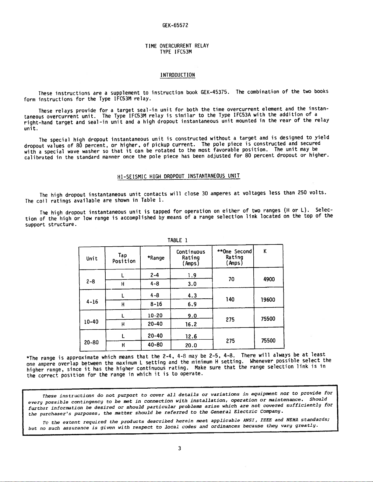
**Higher
The
to
45375
The
target,
the
of
The
pickup,
the
to
ing
retightened.
attached
thereby
obtain
tlng.
attached
is
shading
The
current.
The
currents
high
determine
high
dropout
and
high
dropout
adjustable
while
the
turn
must
determines
percent
80
Should
must
ring
unit
The
Hi-Seismic
Hi—Seismic
High
Inst.
(Amps)
maybeapplied
dropout
the
dropout
turning
core,
loosening
When
held
be
the
dropout
it
be
always
assembly
pick
will
operating
Dropout
Unit
unit
current
instantaneous
current
unit.
(A)
core
the
the
locknut
preveit
to
quietness
at
necessary
be
from
up
time
dropout
high
Hz
is
coil
limiting
is
approximately
sets
core
tightening
or
the
to
turned
being
the
at
is
shown
Movable
Lead
Position
shorter
for
in
series
element
is
unit
pickup
the
(counterclockwise,
up
must
(B)
turning.
from
it
operation
of
minimum
change
in
loosened.
scale-plate
instantaneous
the
in
setting
the
clockwise
Fig.
lengths
with
similar
80
level.
be
loosened.
the
in
dropout
marking
4.
the
for
90
-
locknut,
Rotation
the
and
direction
Fig.
unit
TABLE
Mm.
Pickup
Amps
time
of
time
overcurrent
continuous
both
standard
the
to
percent
Turning
top
After
the
picked
approximately
setting,
or
plus
shows
S
burdens
2
I
Burdens
R
in
accordance
and
instantaneous
the
core
adjusting
the
position.
sleeve
view).
minus
transient
listed
pickup
down
increases
(C)
shading
percent
90
five
Mm.
at
of
the
view)
sleeve
of
up
the
(top
are
Pickup_(Ohms)
unit
short
the
which
to
The
(C)
This
percent
overreach
in
Table
Z
with
the
coil,
time
current.
(clockwise,
pickup.
the
core,
the
sets
ring
core
dropout
which
to
will
with
2.
Burdens
Times_Pickup
3
formula:
Table
see
ratings.
except
unit
Fig.
3
top
Before
locknut
the
shading
dropout
the
been
has
the
at
shading
the
prevent
gradually
characteristics.
in
Ohms
10
and
I,
it
Is
a
view)
must
ring
factory
maximum
the
(Z)
20
GEK
has
picture
lowers
attempt
(D)
level
ring
sleeve
applied
no
be
is
set
set—
and
to
CD)
and
tion
outline
The
diagram
2-8
2-8
4-16
4-16
10-40
10—40
20-80
20-80
is
and
shown
60
50
60
60
[50
panel
in
50
60
50
drilling
Fig.6of
The
0.52
0.22
0.44
0.19
0.13
0.056
0.12
0.052
0.029
0.017
0.025
0.014
0.021
0.013
0.017
0.011
internal
connec
0.77
2
4
2
4
4
8
4
8
10
20
10
20
20
40
20
40
INSTALLATION
is
shown
0.26
0.68
0.24
0.22
0.079
0.19
0.069
0.045
0.020
0.039
0.017
0.025
0.018
0.021
0.015
instruction
in
0.66
0.16
0.56
0.13
0.18
0.030
0.14
0.030
0.027
0.007
0.024
0.006
0.008
0.001
0.007
0.001
book
diagram
this
2-4
4-8
2-4
4—8
4-8
8-16
4-8
8-16
10-20
20-40
10-20
20-40
20-40
40-80
20-40
40-80
supplement.
L
H
L
H
L
H
L
H
L
H
L
H
L
H
L
H
0.66
1.02
0.23
0.30
0.60
0.88
0.22
0.27
0.18
0.29
0.061
0.084
0.024
0.075
0.053
0.021
0.046
0.018
0.027
O.OU
0.022
O.0l0.O12
GEK-45375.
0.16
0.056
0.037
0.018
0.032
0.015
0.022
0.014
0.018
0.52
0.22
0.48
0.19
0.14
0.056
0.13
0.054
0.032
0.017
0.028
0.014
0.022
0.014
0.018
0.012
4
Page 5
GEK-b5512
TIME
IN
SEALTARGET
TIME
FOR
OVERCURRENT
UNIT
AL-N
E
T
AROFT
TAP
SE[.LCT
DR
DIAL
SELECTION
TAP
N
--
INSTANTANEOUS
RANGE
BLOCK
UNIT
SELECTION
LINK
SEAL-IN
FOR
TARGET
INSTANTANEOUS
OVERCURRENT
UNIT
SEAL-IN
TAP
TARGET
SELECTOR
SCREW
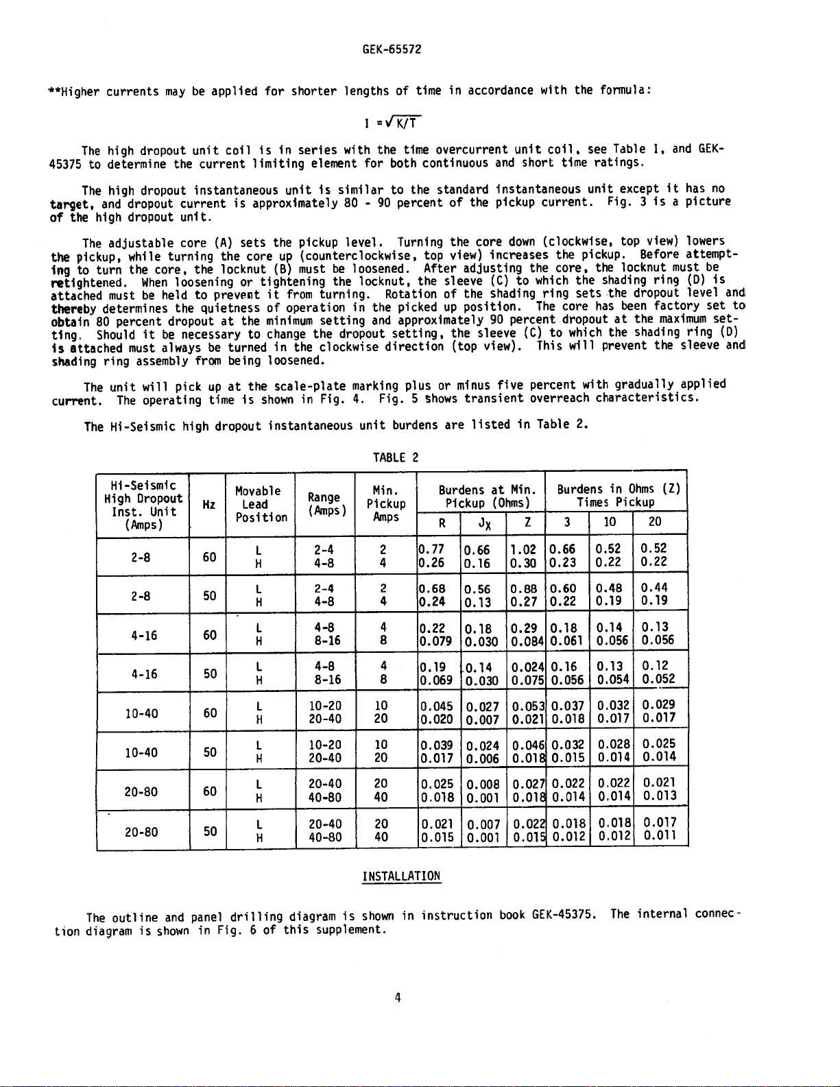
Fig.
(8043607)
1
Type
IFC53M
Relay,
5
Renoved
fro
Cise.
Front
‘[lew
Page 6

INS
IANTANEOUS
HIGH
DROPOUT
UNIT
WITH
ADJUSTABLL
/
CORE
-MAGN
ASSEMBL’
TIME
OVERCURREN
UNIT
El
FOR
Fig.
2
(8O436O8
Type
IFC53M
Relay,
6
Removed
from
Case,
Rear
View
Page 7
ADiUSABLE
LOCKNUT(B)
)tL
E’
CORE
(A)
..‘--
—
—SHADING
-
RiNG(D
high
the
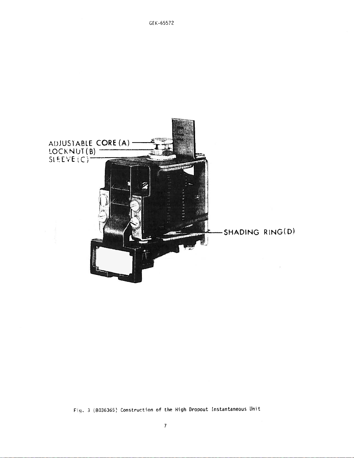
.3
Fi1.
8O3b363
Construction
of
1
Dropout
Instantaneous
Linit
Page 8
GE
K-6
557?
c
030
.
0.025
0
LI
U,
o.c20
LI
—
OPERATING TIME
RANGE
PICKUP
ANY
FOR
SETTING
0.015
D
0
0010
005
o.
0
0
1
2
3
4
MULTIPLES
5
OF
PICK—UP
6
7
8
9
10
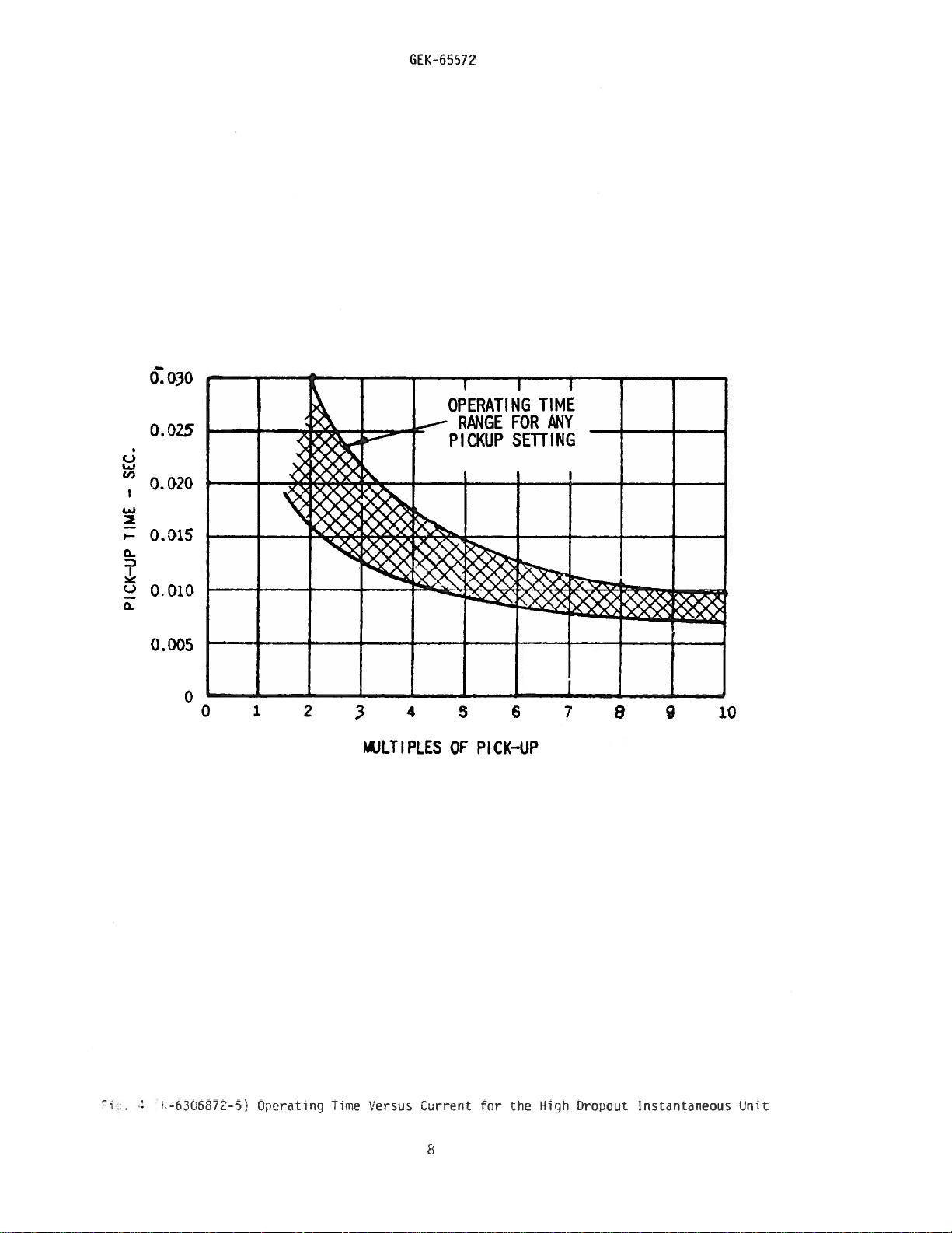
F-€UbR7-5)
O;erting
Ti
e
Vrsus
Current
for
the
Hich
Dropout
Instantaneous
(int
Page 9
‘-I,
7c
4
TTiJTf
-fL:
HtL
fmHtT.1-.I-n
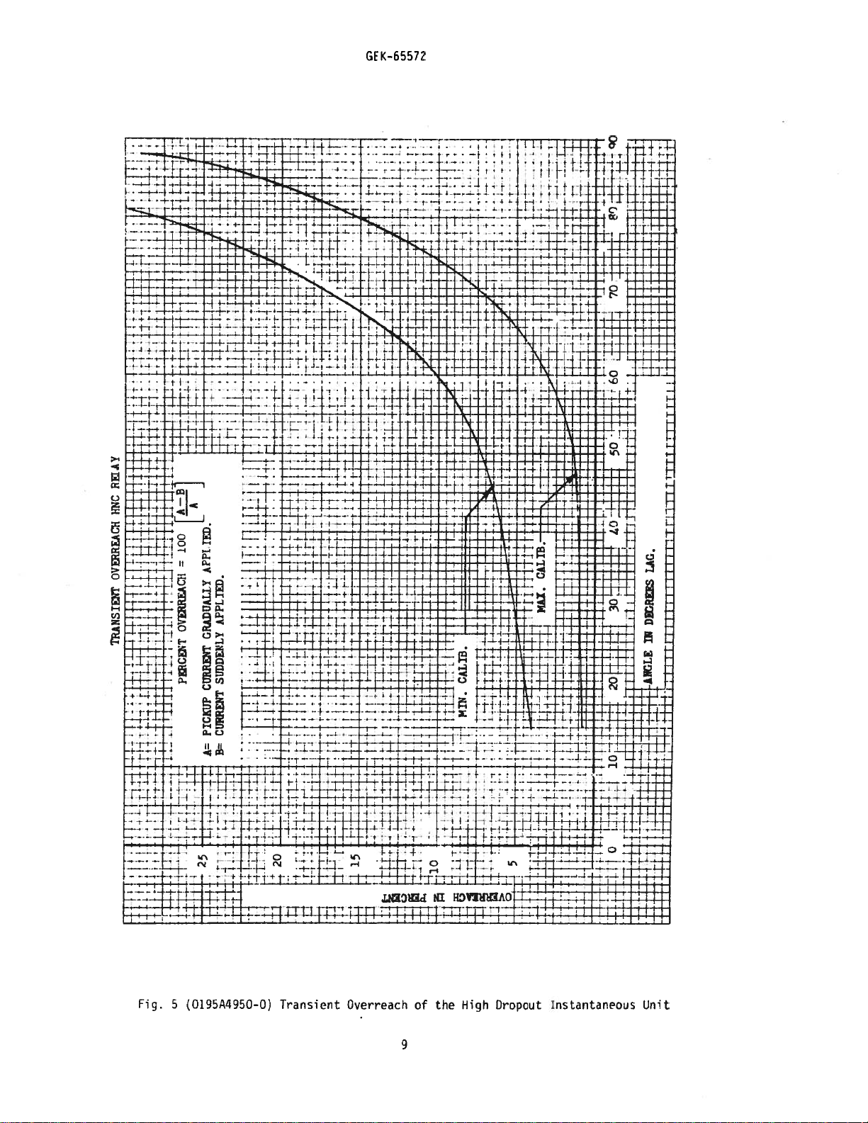
REAY
HNC
0VEN.REACH
TRANSIENT
L
Lfljff.-}
4
_u:.
TiI
.f1t_H
—
Ti:ii
I
f-
4
t—+
Vt
-I--.
.-.--
ft
-
1.
-H-4-1
ri
100
EAC}1
OV
PCENT
ii
i4E:.
i
-*H
441+-
+
llII
f.1..’
1
-H-f-i-!
tt-f-l
WI
I
1t
Ht
.H-ll-
-
4-z
-1-’
Tf
H
TED.
APPI
APPLIED.
GRADUALI.Y
SUDDENLY
CURR2T
PICKUP
CURRENT
B=
A=
t
4
.-t
1.-f
•
--I
1:
25
4.
—
-‘4--
-
,4.
-
T_i
Ii
JiiT
t--
H-
-f
‘-4
-tY
-:
:tf
±±
-r-t-t
4
j
;4.-44
I
4
-4.
1—
f
I
20
-4
41
4
-1--ftt
-h-H*
T
•—;-t
..4-_.4._._•,
1--
i
it
:;
4H-
—
-4
‘4-.
4
f
.ZE
V
4
f-Vt
f:t
ii
t•!-f..
—
-
4,
-if-.
Tfl1f
4
H
-
4
H-
4
H:
I
•i
15
-f-
-H
E
3..
.-4
-
.
•,
4..
t
t__+
—4-,
-
4-.
H
I
-‘-$A
-
-,-j--i-,-
tfI!II,H.f4-:b
i*t-i.
—s--’
-1-_-1_
4
-tfl-
--f-f’
----4----I---1--4---
I—+-,--j-H-—-
-I
•
L1i
(Ir
h-t-t-r-t-I--t-t
CALm.
ll:Fit:
-.
jiL:j
IT
1::
•
-I-I-’
T
4-1-
±Vt-
t-
-
14
-±tt------f
H-f+
i-H-u
CALTh.—
H
MAX.
--H-f
IT
TEETTr
-
-+
1—
—
-
-—:-
tIT
t---
‘-f-rj--I--
:r
-+
ItT
---H
—ti
fZZl44
;!
-I
‘i:i
‘_11j,4
I’
5-i
—
—
—I-
1--1-+
-
1-4
4-
;4...
.1_I
F
4
ii
It
go
-
J17O
‘:•
fl4$:
rEdil
4
:$1tfl
ztt
111111:11,
11111
ill
---44.--,-.-
L
60
50
4-
-
I--’
140
tttfii
30
:1±1
20
‘
1
oH-
.1-f
+11-
-[f-i
r:lo
1fIiTTtTTTi
I
LAG.
I I
I1fI
DrREES
I
IN
±LLtLHffFJJ
I
j-4NGLE
LI4
:1W:
‘TTT
1
Ii
0.
D
-3
0)
c-
-5
-3
0)
n
C-h(0
‘
=
I-
C
V
C
C
3)
0)
0)
C
V
C
Page 10

GEK-65572
INDUCT
ION
LNSTANTANEOUS
HI
DROPOUT
N
SI
*
Fig.6(o275A4554-a)
*
2
=
SHORT
FINGER
Internal
Connection
10
Diagram
for
Type
(0
IFC53M
Relays
Page 11

Page 12

GE
Power
Management
Anderson
215
Markham,
Canada
Tel:
Fax:
www.ge.comlindsyslpm
L6E
(905)
(905)
Avenue
Ontario
1B3
294-6222
201-2098
Page 13
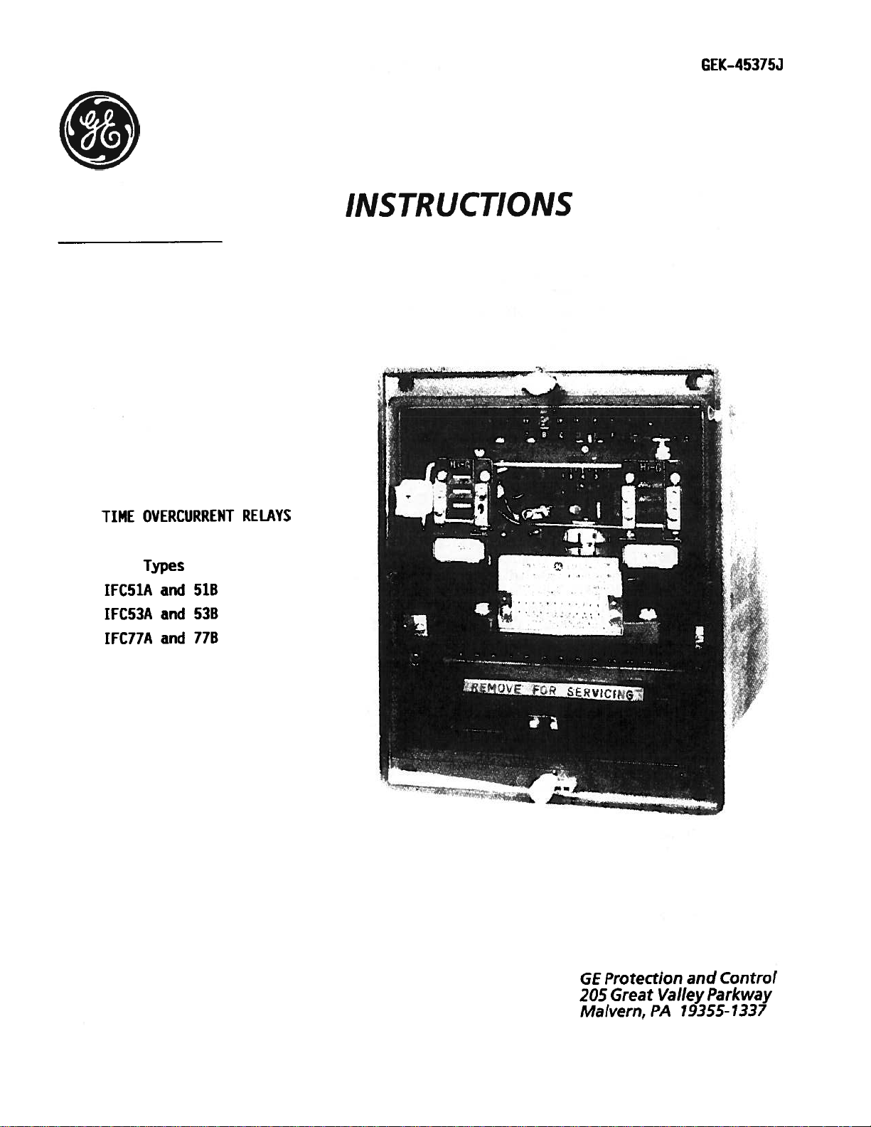
INSTRUCTIONS
GEK—45375J
OVERCURRENT
TIME
Types
IFC51A
IFC53A
IFCJ7A
and
and
and
RELAYS
51B
53B
778
Protection
GE
Great
205
Malvern,
and
Valley
19355-1337
PA
Control
Parkway
Page 14
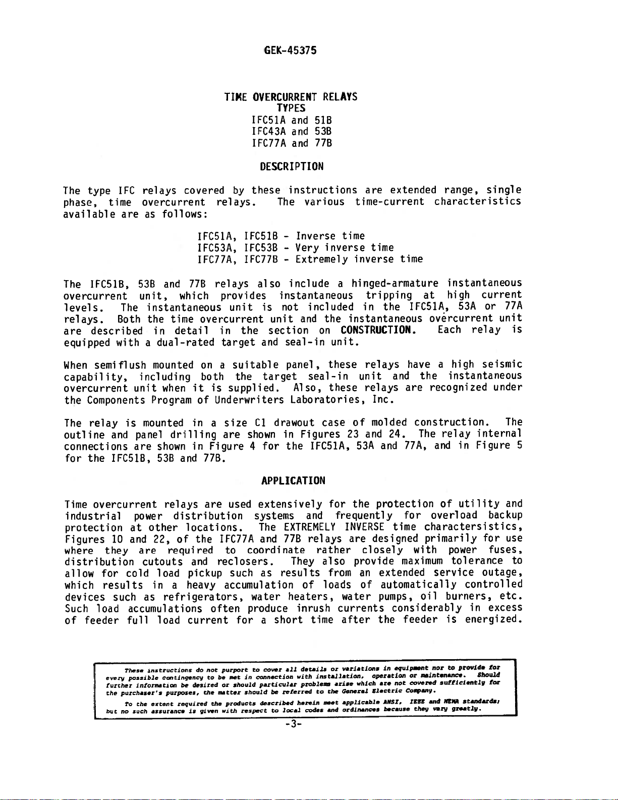
GEK-45375
CO
N
TENTS
DESCRIPTION
APPLICATION
CONSTRUCTION
RATINGS
TIME
OVERCURRENT
HIGH-SEISMIC
HIGH-SEISMIC
CONTACTS
BURDENS
CHARACTERISTICS
TIME
OVERCURRENT
HIGH-SEISMIC
HIGH-SEISMIC
RECEIVING,
ACCEPTANCE
VISUAL
HANDLING
TESTS
INSPECTION
MECHANICAL
DRAWOUT
GENERAL
TIME
RELAY
POWER
OVERCURRENT
HIGH-SEISMIC
HIGH-SEISMIC
UNIT
INSTANTANEOUS
TARGET
AND
UNIT
INSTANTANEOUS
TARGET
AND
AND
STORAGE
INSPECTION
TESTING
REQUIREMENTS
UNIT
INSTANTANEOUS
TARGET
AND
UNIT
SEAL-IN
UNIT
SEAL-IN
UNIT
SEAL-IN
UNIT
UNIT
UNIT
3
3
5
6
6
7
8
8
9
10
10
10
10
10
11
11
H
12
12
12
13
14
INSTALLATION
INSTALLATION
PERIODIC
CHECKS
TIME
OVERCURRENT
HIGH-SEISMIC
HIGH-SEISMIC
CONTACT
COVER
SYSTEM
SERVICING
TIME
OVERCURRENT
HIGH-SEISMIC
HIGH-SEISMIC
RENEWAL
LIST
OF
PARTS
FIGURES
TESTS
AND
INSTANTANEOUS
TARGET
CLEANING
CLEANING
TEST
INSTANTANEOUS
TARGET
ROUTINE
UNIT
AND
UNIT
AND
MAINTENANCE
UNIT
SEAL-IN
UNIT
UNIT
SEAL-IN
UNIT
—2-
15
15
16
16
16
16
16
17
17
17
17
19
19
20
40
Page 15
GE
K-
45375
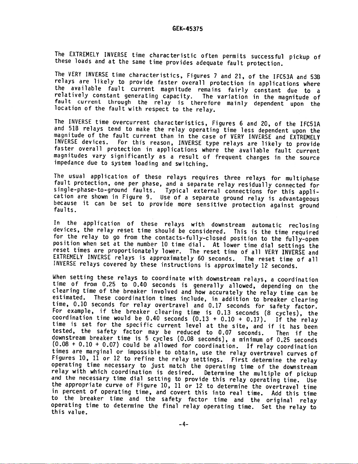
type
The
phase,
available
IFC51B,
The
overcurrent
levels.
relays.
described
are
equipped
When
semi
capability,
overcurrent
Components
the
IFC
time
Both
with
flush
are
538
unit,
The
including
unit
relays
covered
overcurrent
follows:
as
and
which
instantaneous
time
the
detail
in
dual-rated
a
mounted
when
Program
relays.
IFC51A,
IFC53A,
IFC77A,
778
relays
overcurrent
on
both
is
it
of
Underwriters
TIE
by
IFC51B
1FC538
IFC77B
provides
unit
the
in
target
suitable
a
the
supplied.
OVERCURRENT
TYPES
IFC51A
IFC43A
IFC77A
DESCRI
these
also
and
and
and
PTION
instructions
various
The
—
Inverse
—
Very
Extremely
-
include
518
53B
778
instantaneous
included
not
is
and
unit
section
and
seal-in
on
panel,
target
seal-in
Also,
Laboratories,
RELAYS
are
time-current
time
inverse
time
inverse
hinged-armature
a
tripping
in
instantaneous
the
CONSTRUCTION.
unit.
these
relays
unit
these
relays
Inc.
extended
time
the
and
at
IFC51A,
have
the
are
range,
characteristics
instantaneous
high
53A
overcurrent
Each
a
relay
high
instantaneous
recognized
single
current
or
unit
seismic
under
77A
is
relay
The
outline
connections
for
the
Time
overcurrent
industrial
protection
Figures
where
they
distribution
allow
which
for
results
devices
Such
of
load
feeder
every
further
the
but
is
mounted
and
panel
are
IFC51B,
power
at
10
and
are
cutouts
cold
as
such
accumulations
full
These
possible
information
purchasers
Do
the
no
such
drilling
shown
53B
relays
distribution
other
22,
of
required
load
in
a
refrigerators,
load
instructions
continqenry
purposes,
required
extent
assurance
in
in
77B.
and
are
locations.
the
and
pickup
heavy
current
do
desired
be
the
given
is
size
a
are
Figure
used
IFC77A
to
reclosers.
such
accumulation
often
for
not
purport
met
to
be
or
should
matter
products
the
with
drawout
Cl
shown
for
4
APPLICATION
extensively
systems
The
and
coordinate
results
as
water
produce
short
a
cover
to
connection
jn
particular
be
described
to
referred
local
should
respect
case
in
Figures
the
IFC51A,
for
and
frequently
EXTREMELY
77B
relays
rather
They
also
from
loads
of
heaters,
inrush
time
codes
or
installation.
arise
the
to
meet
and
details
all
with
problee’
herein
-3—
of
and
23
53A
the
INVERSE
are
closely
provide
an
of
water
currents
after
variations
which
General
applicable
ordinances
molded
24.
77A,
and
protection
for
time
designed
maximum
extended
automatically
pumps,
considerably
feeder
the
equipnt
in
are
ANSI,
because
or
covered
not
CoaflY.
operation
Electric
construction.
relay
The
and
of
overload
charactersistics,
primarily
with
power
tolerance
service
burners,
oil
is
to
flat
wsintananCe
sufficientl
NE
and
IEEE
vary
thei
gr.atly.
internal
Figure
in
utility
for
outage,
controlled
in
energized.
provide
Should
standards,
The
5
and
backup
use
fuses,
to
etc.
excess
for
for
Page 16
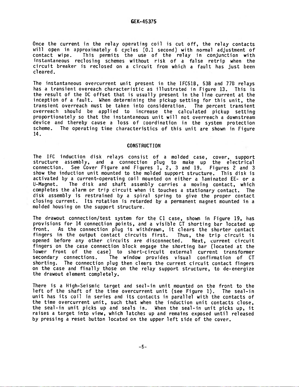
The
EXTREMELY
these
The
relays
the
relatively
fault
location
The
and
magnitude
INVERSE
faster
magnitudes
impedance
The
fault
single—phase-to—ground
cation
because
fa
VERY
available
INVERSE
513
usual
u
1
t
s.
loads
INVERSE
are
current
of
relays
devices.
overall
protection,
are
it
INVERSE
and
likely
constant
the
time
of
the
vary
due
to
application
shown
can
at
time
fault
through
fault
tend
protection
significantly
system
in
be
time
the
same
characteristics,
to
provide
current
generating
with
overcurrent
to
fault
one
For
current
this
loading
of
per
faults.
Figure
set
characteristic
time
the
respect
make
in
these
phase,
9.
provide
to
GEK—45375
provides
faster
magnitude
capacity.
relay
to
characteristics,
the
relay
than
reason,
applications
as
a
and
switching.
relays
and
Typical
Use
of
adequate
Figures
overall
remains
is
therefore
the
relay.
operating
in
the
INVERSE
result
requires
separate
a
external
a
separate
more
sensitive
often
protection
The
case
type
where
of
permits
7
and
variation
Figures
time
of
relays
the
frequent
three
relay
connections
ground
fault
21,
fairly
mainly
6
VERY
available
residually
protection
successful
protection.
of
in
constant
in
dependent
and
less
INVERSE
are
changes
relays
relay
the
IFC53A
applications
the
magnitude
20,
of
dependent
and
likely
fault
in
for
connected
for
this
is
advantageous
against
pickup
and
53B
where
due
to
upon
the
upon
EXTREMELY
to
the
multiphase
the
IFC51A
the
provide
current
source
for
appli
ground
of
a
of
In
the
devices,
for
the
position
reset
EXTREMELY
INVERSE
When
time
clearing
estimated.
time,
For
coordination
time
times
relays
setting
of
0.10
example,
is
tested,
downstream
(0.08
times
Figures
+
are
0.10
10,
operating
relay
and
the
in
to
with
the
necessary
appropriate
percent
the
breaker
operating
this
value.
application
the
relay
relay
when
time
set
the
set
are
INVERSE
these
from
of
These
seconds
if
time
for
safety
breaker
+
marginal
11
time
which
of
time
reset
to
go
from
at
the
proportionately
relays
covered
relays
0.25
to
the
breaker
coordination
for
the
breaker
would
the
specific
factor
time
0.07)
could
or
or
12
to
necessary
coordination
time
curve
of
operating
time
to
determine
of
these
time
the
number
is
by
these
to
0.40
relay
be
0.40
may
is
5
be
impossible
refine
to
dial
setting
Figure
time,
and
the
the
relays
should
contacts—fully-closed
10
time
lower.
approximately
instructions
coordinate
seconds
involved
times
overtravel
clearing
seconds
current
be
cycles
allowed
to
the
relay
just
is
match
desired.
10,
and
covert
safety
final
be
is
and
include,
time
level
reduced
(0.08
for
obtain,
to
provide
11
or
factor
relay
with
considered.
dial.
The
with
generally
(0.13
settings.
the
downstream
At
reset
60
seconds.
is
approximately
downstream
how
accurately
in
and
0.17
is
0.13
+
0.10
at
the
to
0.07
seconds),
coordination.
use
the
operating
Determine
this
12
to
determine
this
into
time
operating
This
position
lower
time
allowed,
addition
seconds
seconds
site,
a
relay
First
relay
real
and
automatic
is
time
all
of
The
relays,
the
to
for
+
0.17).
and
seconds.
minimum
If
overtravel
determine
time
the
multiple
operating
the
time.
the
time.
the
to
the
dial
VERY
reset
12
seconds.
a
depending
relay
breaker
safety
(8
if
of
relay
of
the
overtravel
Add
original
Set
reclosing
time
required
fully—open
settings
INVERSE
time
coordination
cycles),
If
it
Then
0.25
time
of
on
can
clearing
factor.
the
has
if
seconds
coordination
curves
the
downstream
pickup
of
time.
this
the
relay
the
and
all
the
be
the
relay
been
the
of
relay
Use
time
time
relay
to
—4-
Page 17
GEK-45375
Once
will
contact
circuit
overreach
device
The
connection.
activated
completes
disk
closing
molded
the
open
wipe.
instantaneous
breaker
cleared.
The
instantaneous
has
the
inception
transient
proportionately
scheme.
14.
structure
show
i-Magnet.
transient
a
result
and
IFC
the
assembly
current.
housing
induction
current
in
approximately
reclosing
of
the
of
a
overreach
should
thereby
The
operating
induction
assembly,
See
by
a
The
the
alarm
on
in
the
relay
This
is
overeach
DC
fault.
so
Cover
current—operating
disk
is
Its
the
permits
reclosed
overcurrent
characteristic
offset
When
must
be
applied
that
the
cause
time
disk
and
Figure
unit
mounted
and
or
trip
restrained
rotation
support
schemes
be
relays
operating
6
cycles
the
without
on
a
unit
is
that
determining
taken
to
instantaneous
loss
a
characteristics
CONSTRUCTION
consist
connection
a
and
to
coil
shaft
circuit
by
a
is
structure.
(0.1
use
circuit
present
usually
into
increase
of
coordination
Figures
the
mounted
assembly
when
spiral
retarded
coil
second)
the
of
risk
from
in
as
illustrated
present
the
pickup
consideration.
the
unit
of
of
a
plug
1,
2,
molded
it
carries
touches
spring
by
support
on
a
is
cut
relay
of
which
the
setting
calculated
will
this
molded
to
3
either
to
permanent
off,
with
false
a
a
IFC51B,
in
in
the
not
overreach
the
in
unit
case,
make
and
structure.
moving
a
a
stationary
give
normal
in
fault
Figure
line
The
are
up
19.
a
laminated
the
magnet
the
relay
adjustment
conjunction
retrip
has
53B
and
current
for
this
percent
pickup
system
shown
cover,
the
Figures
contact,
contact.
proper
contacts
when
just
77B
13.
unit,
transient
downstream
a
protection
in
electrical
2
This
EE-
mounted
with
been
relays
This
at
setting
Figure
support
and
disk
or
which
contact
in
of
the
is
the
the
3
is
a
The
a
The
drawout
provisions
front.
fingers
opened
fingers
lower
secondary
shorting.
on
the
the
drawout
There
left
of
unit
has
the
time
seal—in
the
raises
by
pressing
As
in
before
on
front
case
is
a
the
its
overcurrent
a
target
connection/test
for
the
the
the
connections.
The
and
element
High-Seismic
shaft
unit
a
14
connection
output
any
case
the
of
connection
finally
coil
picks
into
reset
connection
contact
other
connection
case)
completely.
of
the
in
series
unit,
up
view,
button
circuits
The
plug
those
target
time
and
which
located
system
points,
plug
to
and
such
for
is
withdrawn,
circuits
are
block
short-circuit
window
then
clears
on
the
and
seal-in
overcurrent
its
contacts
that
seals
latches
on
the
and
a
first.
disconnected.
engage
provides
relay
when
in.
up
the
upper
—5—
Cl
visible
the
the
support
unit
unit
the
When
and
case,
it
shorting
external
current
(see
in
parallel
induction
the
remains
left
shown
CT
clears
Thus,
visual
structure,
mounted
Figure
seal—in
side
shorting
the
the
Next,
bar
current
confirmation
circuit
on
with
unit
exposed
of
in
the
1).
unit
the
Figure
bar
shorter
trip
current
(located
contact
to
front
the
contacts
picks
until
cover.
19,
located
contact
circuit
circuit
at
transformer
of
fingers
de-energize
to
The
seal—in
contacts
close,
up,
released
has
up
is
the
CT
the
of
it
Page 18

The
IFC
instantaneous
type
unit
overcurrent
contacts
with
raises
same
target
A
of
the
a
reset
of
magnetic
inverse
eliminate
‘SB”
which
of
time
target
the
shield,
and
the
model
unit
is
unit.
the
time
overcurrent
which
button
instantaneous
very
proximity
relays,
(see
mounted
Its
contacts
overcurrent
latches
that
depicted
inverse
effect
in
Figure
on
unit.
releases
unit.
the
up
in
time
GEK—45375
addition
1).
front
are
unit,
When
and
the
Figure
overcurrent
of
external
to
The
instantaneous
to
normally
remains
target
1,
the
the
and
the
is
magnetic
above,
right
connected
its
coil
instantaneous
exposed
until
seal—in
mounted
IFC
relays
materials.
contain
unit
of
is
unit
to
is
the
shaft
In
parallel
connected
unit
it
also
the
support
(IFC51
a
a
is
and
small
picks
released.
releases
high-seismic
hinged—
of
the
with
in
series
up,
structure
1FC53),
time
the
it
The
the
to
Both
the
instantaneous
distinguish
axial
acceleration
frequency
accordance
May,
1977.
The
relays
-20°C
TIME
Ranges
to
OVERCURRENT
for
Relay
IFC51A
IFC53A
IFC77A
High-Seismic
unit
them
input
with
are
+55°C.
the
time
&
B
B
&
B
&
have
High—Seismic
as
of
motion
the
IEEE
designed
UNIT
overcurrent
Frequency
target
the
lOg’s
to
Proposed
50
and
letters
(4g
produce
for
unit
(Hertz)
60
and
“Hi—G”
units.
ZPA)
a
Guide
RAT
operation
are
TABLE
seal-in
Seismic
when
Required
for
I
NGS
shown
I
molded
Seismic
in
an
Current
unit
tested
in
into
Fragility
using
Response
Testing
ambient
Table
Range
0.5
1.0
and
-
-
their
I.
12.0
the
target
Level
a
Spectrum
of
air
temperature
(Amperes)
4.0
High—Seismic
blocks
exceeds
biaxial
(RRS)
Relays,
to
peak
multi—
in
P501,
from
The
current
labeled
The
of
relay
The
one—second
tap
tap
screw
and
taps
block.
settings
tap
thermal
are
range.
selected
are
ratings
as
with
listed
are
two
listed
-6-
sliding
in
Table
in
tap
II,
Table
screws
on
page
III.
on
an
20,
alphabetically
for
each
model
Page 19

GEK—45375
L
Ratings
The
and
4
1FC51
1FC53
1FC77
Model
IFC51
1FC53
1FC77
less
continuous
V.
Model
TABLE
Time
Overcurrent
Unit
(Amperes)
0.5
-
4.0
-
-
-
-
-
second
where
12.0
4.0
12.0
4.0
12.0
for
may
be
the
time
time
T
is
the
1.0
0.5
1.0
0.5
1.0
one
than
JK/T,
I
ratings
TABLE
4.0
0.5
—
Ampere
III
One
calculated
in
overcurrent
IV
Range
Second
seconds
Rating
(Amperes)
128
260
140
260
84
220
according
that
unit
Ratings
the
are
Any
to
Tap
the
current
shown
16384
67600
19600
67600
7056
48400
formula
flows.
in
K
Tables
IV
Tap
3.0
0.5
1.6
3.8
2.5
0.7
0.6
1.8
2.0
4.0 4.2
2.7
3.0
0.8
2.1
4.4
3.2
1.0
2.3
4.7
3.6
1.2
2.7
5.0
4.0
1.5
3.0
5.3
4.5
2.0
3.5
5.8
5.2
2.5
4.0
6.2
5.9
4.0
5.0
4.5
7.1
6.6
6.5 7.5
Model
IFCS1
1FC53
1FC77
1.0
3.7
6.8
5.8
HIGH-SEISMIC
instantaneous
The
L).
link
Selection
located
or
the
VI).
1.0
1.5
4.6
7.7
7.2
2.0 2.5
5.3
8.3
8.4
1.2
4.1
7.1
6.4
INSTANTANEOUS
coil
on
of
is
the
the
6.0
8.8
9.4
UNIT
tapped
high
top
TABLE
12.0
Ampere
-
V
Range
Ratings
Tap
ranges
and
12.0
13.2
14.41
21.
(H
of
Table
of
3.0
10.4
or
the
6.5
9.4
for
low
4.0
7.6
10.3
12.1
operation
range
support
5.0
8.5
11.0
13.6
is
structure
6.0
9.3
11.6
15.1
either
on
determined
7.0
10.0
12.4
16.4
(see
one
8.0
10.8
12.6
17.6
of
by
Figure
the
10.0
12.1
13.5
19.8
two
position
2
-7-
Page 20

GEK—45375
Since
coil,
for
High—Seismic
Instantaneous
Unit
2
-
6-150
The
8-50.
maximum
sure
rating.
Higher
accordance
the
instantaneous
see
Tables
both
continuous
(Amps)
50
range
to
is
There
L
setting
select
currents
with
III,
Link
Position
L
H
L
H
approximate,
will
always
and
the
higher
may
the
formula:
I
=
v’K/T
unit
IV,
V
and
short—time
be
coil
and
Range
(Amps)
2
10
30
the
TABLE
-
10
-
50
6
30
-
150
which
be
at
minimum
range,
applied
is
VI
to
ratings.
means
least
in
series
determine
VI
Continuous
Rating
(Amps)
2.7
7.5
10.2
19.6
that
one
H
setting.
since
for
it
shorter
with
Second
Rating
(Amps)
130
260
the
2—10,
ampere
Whenever
has
the
the
time
the
current—limiting
One
10-50
overlap
higher
lengths
K
16,900
67,600
may
between
possible,
continuous
of
overcurrent
be
time
element
2-8,
the
be
in
unit
HIGH-SEISMIC
Ratings
for
DC
Mm.
Carry
Carry
Carry
60
If
the
tripping
the
connections
contacts
or
CONTACTS
The
current-closing
exceeding
the
seal—in
250
TARGET
the
target
Resistance
Operating
Continuous
30
Amps
Amps
10
Hz
Impedance
current
being
the
target
volts.
unit.
AND
and
±
for
for
such
and
rating
The
SEAL—IN
UNIT
seal-in
10%
(ohms)
(Amps)
+0
(Amperes)
(sec.)
(sec.)
(ohms)
exceeds
that
30
the
seal-in
of
the
current-carrying
unit
TABLE
-60%
amperes,
tripping
coils
contacts
are
VII
of
shown
an
current
the
is
rating
in
0.2
8.0
0.2
0.3
0.03
0.25
68.6
auxiliary
protective
30
is
Table
Tap
relay
does
amperes
limited
VII.
not
relay.
2
0.24
2.0
3
4
30
0.73
pass
for
by
should
voltages
the
be
through
ratings
used,
the
not
of
-8-
Page 21

GEK—45375
BURDENS
Burdens
Model
Note:
for
the
Hz
IFC51
1FC53
1FC77
IFC51
1FC53
1FC77
The
60
60
60
50
50
50
impedance
Impedance
(approximately)
relay
Hz
60
amp
0.5
0.176
tap.
ohms.
time
Range
0.5—
1.0—12.0
0.5—
1.0—12.0
0.5—
1.0-12.0
0.5-
1.0—12.0
0.5—
1.0—12.0
0.5—
1.0-12.0
for
with
overcurrent
4.0
4.0
4.0
4.0
4.0
4.0
values
as
taps
the
other
0.5
impedance
The
Mm
Tap
Amps
0.5
1.0
0.5
1.0
0.5
1.0
0.5
1.0
0.5
1.0
0.5
1.0
given
square
—
4.0
at
unit
TABLE
Burdens
Pickup
R
5.43
1.47
1.52
0.38
1.55
0.59
4.53
1.22
1.27
0.32
1.29
0.49
are
pickup
of
amp
of
are
(Ohms)
those
the
range
the
given
vrir
at
Mm.
Jx
21.53
5.34
4.23
1.06
2.36
0.43
17.95
4.45
3.52
0.88
1.97
0.36
for
current
tap
has
2.0
In
Mm.
Tap
Z
22.20
5.54
4.50
1.13
2.82
0.73
18.50
4.62
3.75
0.94
2.35
0.61
minimum
(tap
rating.
an
amp
tap
Table
Burdens
(Z)
3
12.55
3.09
4.47
1.11
2.86
0.74
11.45
2.58
3.72
0.93
2.38
0.62
tap
rating)
For
impedance
(0.5/2.0)2
Is
VIII.
Times
of
example,
of
in
10
5.14
1.28
3.10
0.78
2.93
0.75
4.28
1.07
2.58
0.65
2.44
0.63
each
varies
2.82
Ohms
Pickup
20
3.29
0.82
1.93
0.49
2.76
0.70
2.70
0.68
1.61
0.41
2.30
0.58
range;
inversely
an
ohms
2.82
x
the
1FC77
on
=
the
High—Seismic
The
High—
Seismic
Inst.
Unit
(Amps)
2—50
6—150
2
50
6—150
Hz
60
60
50
50
instantaneous
Link
Posi—
Range
(Amps)
tion
L
H
L
H
L
H
L
H
2-10
10—50
6-30
30—150
2—10
10-50
6-30
30-150
unit
Mm.
Pick-
up
Amps
2
10
6
30
2
10
6
30
burdens
TABLE
Burdens
Pickup
R
0.750
0.070
0.110
0.022
0.625
0.058
0.092
0.018
are
IX
at
Mm.
(Ohms)
0.650
0.024
0.078
0.005
0.542
0.020
0.065
0.004
listed
Mm.
Tap
Z
0.982
0.079
0.135
0.023
0.827
0.062
0.112
0.019
in
Table
Burdens
(Z)
3
0.634
0.072
0.095
0.022
0.528
0.060
0.079
0.018
IX.
Times
10
0.480
0.071
0.081
0.022
0.400
0.059
0.068
0.018
in
Ohms
Pickup
20
0.457
0.070
0.079
0.022
0.380
0.058
0.066
0.018
9
Page 22

GEK—45375
TIME
OVERCURRENT
Pickup
Pickup
contacts
of
two
structure
through
A
Example:
Operating
The
IFC
0.10
and
The
the
second,
20-22
setting
contacts
longer
The
contacts
setting
maximum
in
from
movable
(see
N.
The
movable
Time
relays
show
the
operating
occurs
distance
these
the
leads
Figure
See
amp
2
Accuracy
should
whichever
the
of
the
for
are
when
UNIT
relays
0.5
the
tap
lead
a
just
to
time
which
1).
nameplate
in
various
time
given
time.
closed
the
close
is
The
for
position
operate
is
greater,
dial
time
the
CHARACTIERISTI
defined
dial
position.
connect
1
a
tap
to
on
block
the
12
D
to
and
within
of
time-current
determines
current.
when
dial
the
is
contacts.
as
the
relay
1FC77
the
.
the
The
time
set
is
the
to
Cs
the
current
Current
tap
block
marked
for
tap
time
overcurrent
other
7%
or
.
published
characteristics
length
higher
dial
10
is
and
A
in
the
the
set
the
required
settings
at
through
settings.
position
time
time
of
time
time
to
disk
the
are
top
J,
relay
dial
curve.
for
required
dial
0.
has
H.
The
of
A
the
to
to
close
made
the
through
requires
setting
Figures
IFC
setting,
maximum
travel
by
support
relays.
to
the
means
N
one
times
6—8
close
the
time
its
or
Reset
The
unit
proportionate
time
seconds
dial
for
approximately
HIGH-SEISMIC
The
instantaneous
and
low
ranges,
structure.
is
shown
in
HIGH-SEISMIC
The
target
unit.
These
cartons
See
relays,
designed
resets
position
to
the
12
at
the
when
1FC53
seconds
time
INSTANTANEOUS
unit
selected
See
Figure
Figure
TARGET
and
Figure
when
seal-in
1.
to
14.
AND
not
protect
90%
of
dial
the
and
from
UNIT
has
a
by
means
1.
The
SEAL-IN
unit
has
RECEIVING,
included
them
the
settings.
current
77
the
25
to
time-current
UNIT
two
as
minimum
is
relays.
same
number
I
range
of
a
tap
link
selections
HANDLING
part
of
against
closing
The
reduced
The
10
with
located
curve
AND
a
control
damage.
current.
time
to
to
IFC5I
time
dial.
tapped
a
on
for
located
STORAGE
panel,
Immediately
reset
0
relay
coil.
the
the
is
Reset
to
the
approximately
will
There
top
of
instantaneous
on
the
front
will
be
upon
times
number
reset
are
the
shipped
receipt
high
support
unit
of
the
are
10
60
in
in
of
-10-
Page 23

relay,
a
resulting
transportation
Office.
Reasonable
parts
the
of
relays
the
If
their
original
metallic
way
its
relay.
the
of
examine
from
care
are
chips.
inside
it
rough
company
should
injured
not
are
cartons
Foreign
when
for
handling
and
be
to
the
any
exercised
or
be
in
matter
cover
damage
is
promptly
adjustments
the
installed
place
a
is
GEK-45375
sustained
evident,
notify
in
that
collected
removed,
in
a
file
the
unpacking
disturbed.
immediately,
is
the
on
and
transit.
damage
nearest
the
free
outside
cause
claim
General
relay
they
from
trouble
injury
If
at
in
should
moisture,
the
of
in
once
Electric
order
be
case
the
or
damage
with
Sales
that
stored
dust
may
operation
the
none
in
and
find
Immediately
should
that
test
be
the
indicates
relay
SERVICING.
These
tests,
Since
tests
at
most
installation
performed
be
may
VISUAL
Check
INSPECTION
the
calibration
Remove
no
the
broken
MECHANICAL
There
1.
clockwise.
upon
made
to
calibrations
that
be
may
discretion
the
operating
tests,
on
nameplate
range
relay
cracked
or
INSPECTION
should
receipt
insure
performed
the
these
the
of
from
molded
be
disk
The
of
that
have
readjustment
the
of
companies
following
relays.
stamping
relay
case
its
parts
noticeable
no
should
ACCEPTANCE
relay,
the
damage
no
been
not
is
as
part
of
user.
different
use
section
insure
to
received
check
and
other
or
friction
return
TESTS
an
has
disturbed.
necessary,
installation
the
includes
that
agree
by
signs
itself
by
inspection
been
procedures
the
the
with
visual
of
when
to
sustained
If
refer
all
model
requisition.
inspection
physical
disk
the
its
acceptance
and
the
the
to
of
or
for
applicable
number,
damage.
is
position.
rest
shipment
in
examination
section
acceptance
the
acceptance
tests
rating
that
rotated
there
test
and
or
on
and
that
and
are
slowly
convolutions
its
as
move
on
nor
well
the
freely
by
as
when
seal-in
unit
hand
the
armature
operated
and
must
and
the
come
sh®uld
not
1/64”
in
is
deformed,
unit,
should
wipe
instantaneous
the
operated
are
operated.
at
unit
is
seal-in
the
unit,
least
and
armatures
button
control
or
when
the
touching
and
of
there
contacts.
in
and
the
each
contacts
the
should
the
latch
target
Make
2.
sure
tangled
armature
The
3.
contacts
and
hand;
by
instantaneous
targets
The
4.
view
into
unlatch
spring
other.
of
instantaneous
be
seal-in
when
the
release
—11—
Page 24

5.
6.
Make
connections
Check
sure
that
that
diagram.
all
the
screws
brushes
are
tight.
GEK—45
and
shorting
375
bars
agree
with
the
internal
SHOULD
PREVENT
DRAWOUT
The
IFC
12XCA11A1
connections
maximum
is
necessary
using
Figure
GENERAL
All
Since
harmonics
will
test
The
expressed
using
as
waveforms.
recommended.
an
15.
POWER
alternating
non—sinusoidal
be
AC
purity
tuned
time
THERE
STRIPPING.
RELAY
relays
flexibility
affected
relays
overcurrent
TESTING
four-point
to
when
ammeter
REQUIREMENTS
of
the
of
as
a
circuits,
Hence
BE
A
may
be
both
but
testing
instead
current
waveforms
fundamental
by
the
it
is
the
sine
finite
relays)
a
resistance-limited
NEED
tested
test
the
requires
(AC)
applied
essential
wave
number
R-L
TO
probes.
relay
the
of
or
would
TIGHTEN
without
and
reasonable
relay.
the
shorting
operated
can
frequency,
waveform.
to
(i.e.,
for
RC
networks,
CAUTION
ANY
removing
The
the
The
be
analyzed
use
a
its
any
particular
be
essentially
circuit,
SCREWS,
theni
12XCA1JA2
external
care,
CT
circuit
jumper.
devices
as
it
follows
Therefore,
sine
wave
freedom
or
saturating
as
DO
NOT
from
four-point
circuitry,
since
See
are
affected
a
fundamental
that
of
current
from
relay;
affected
shown
OVERTIGHTEN,
the
panel
test
which
a
CT
shorting
may
also
the
test
by
frequency
AC
devices
in
order
and/or
harmonics)
however,
electromagnets
by
non-sinusoidal
in
Figures
by
using
probe
be
tested
circuit
frequency.
to
cannot
any
16—18,
TO
the
makes
provides
jumper
by
in
plus
(relays)
properly
voltage.
be
relay
(such
is
TIME
OVERCURRENT
Rotate
just
The
stationary
With
sufficient
strip
The
tap
CHARACTERISTICS
The
adjusted
the
close
point
the
to
ensure
minimum
setting
pickup
by
time
at
the
at
contact
contacts
gap
current
in
of
means
UNIT
dial
C
time
which
the
brush
just
between
approximately
at
the
tap
section.
the
time
of
a
slowly
the
dial
contacts
in
or
closing
and
setting.
out
stationary
1/32”
which
the
block
overcurrent
spring-adjusting
check
just
by
at
wipe.
contacts
at
the
—12-
close
means
No.
contact
unit
by
top
ring.
will
means
of
0
time
of
for
can
its
just
of
be
adjusting
setting,
brush
close
the
any
See
a
lamp
adjusted
and
support
current
Figure
that
screw.
there
its
is
determined
1.
the
by
running
metal
structure.
tap
setting
The
contacts
should
backing
spring
by
the
be
the
See
is
Page 25

GEK—45375
adjusting
1).
into
By
agreement
disturbed.
between
required,
that
the
characteristics
up
pick
been
has
Setting
Time
setting
The
close
to
contacts
on
set
is
therefore
and
primary
The
the
of
permanent
shaft
and
Pickup
Set
Test
the
connections
tap
of
Hz
50
for
ring
turning
the
it
a
at
changed.
the
are
10,
time
magnet
decreases
relay
value
relays.
either
the
with
This
various
recommended
is
relay
of
value
the
of
contacts
just
the
this
adjustment
dial.
along
at
Figure
in
current
winds
ring,
the
adjustment
tap
will
Figures
other
than
time
when
closed
disk
must
setting
for
However,
its
time,
the
time
0.5
16,
for
or
the
tap
settnqs
that
not
6-8
dial
the
when
gives
the
supporting
dial
the
60
unwinds
operating
setting
also
the
necessarily
and
value,
tap
determines
current
time
the
travel
the
time
further
while
position
main
relays
Hz
the
employed,
permits
be
to
higher
20—22
the
maximum
operation
of
shelf;
moving
unit
and
spiral
current
any
obtained.
tap
agree
the
if
because
length
the
reaches
dial
is
maximum
time
adjustment
moving
away
it
and
should
within
set
the
close
control
the
of
this
if
desired
used.
be
with
relay
torque
the
of
predetermined
a
on
amount
setting.
the
of
is
the
increases
lowest
the
7.5%
±
spring
unit
adjustment
setting
such
If
It
the
has
time
0.
to
unit
obtained
magnet
tap.
contacts
of
been
level
the
When
close
is
the
tap
(see
be
may
intermediate
adjustment
should
time
adjusted
of
unit
value.
the
the
made
by
toward
time.
Using
within
value
Figure
brought
has
be
current
the
requires
time
contacts
by
moving
the
the
current
been
noted
relay
The
dial
means
the
disk
test
±
is
to
3%
Test
Time
relay
the
Set
connections
relay
operating
HIGH-SEISMIC
range
5,
and
sure
in
which
connect
Make
possible,
rating.
No.
at
Figure
in
time
Relay
IFC51
1FC53
1FC77
INSTI\NTANEOUS
that
is
it
instantaneous
the
as
higher
the
use
5
time
16,
close
to
—
operate.
to
indicated
range,
dial
apply
UNIT
its
Hz
50
50
50
in
setting
five
contact
and
and
and
unit
See
the
since
times
TABLE
60
60
60
link
the
test
the
—13-
and
is
X
-
is
Internal
higher
the
tap
listed
circuit
in
lowest
current
the
range
tap.
to
Table
in
(seconds)
Time
Mm.
1.76
1.28
0.89
correct
Connections
Figure
of
has
X.
Max.
1.80
1.34
0.95
a
Using
the
position
Diagram,
17.
higher
the
relay.
continuous
test
The
the
for
Figure
Whenever
Page 26

GEK-45375
Setting
The
as
loosen
the
the
this
pickup
the
instantaneous
shown
in
the
pickup;
current
operation
value
REFER
INSTANTANEOUS
CURRENT
The
range
core
of
position
counterclockwise
the
full
clockwise
HIGH-SEISMIC
The
target
amperes.
higher
The
ampere
stationary
the
left-hand
remove
the
stationary
procedure
getting
same
time.
is
out
High-Seismic
unit
Figure
locknut
turning
slowly
until
is
reached,
TABLE
TO
THE
TO
instantaneous
the
of
from
TARGET
and
seal-in
relay
position.
contact.
stationary
screw
contact
necessary
of
adjustment.
Instantaneous
and
until
1.
the
has
adjust
core
the
adjustable
an
To
set
the
counterclockwise
the
unit
desired
tighten
VI
FOR
THE
UNIT.
DO
INSTANTANEOUS
the
of
full
a
1/8
position.
AND
SEAL-IN
is
To
unit
shippped
change
The
has
tap
contact
from
where
the
to
the
undesired
first
prevent
Screws
Unit
the
instantaneous
core.
picks
pickup
the
locknut.
CAUTION
CONTINUOUS
EXCEED
NOT
UNIT.
unit
turn
(see
from
clockwise
UNIT
an
operating
from
the
screw
the
tap
and
place
tap
screw
the
should
core
Turning
up.
value
AND
THESE
Table
position.
factory
is
the
setting,
and
was
right-hand
never
located
unit
the
core
increases
It
may
is
obtained.
ONE-SECOND
RATINGS
VI)
must
full
clockwise
Do
coil
with
screw
first
it
in
the
place
removed
stationary
left
be
at
the
to
the
be
be
not
tapped
the
holding
remove
desired
it
(see
in
top
a
desired
clockwise
pickup.
necessary
Once
RATINGS
WHEN
obtained
and
leave
at
tap
the
one
the
on
Figure
both
of
the
pickup)
decreases
Bring
to
repeat
the
desired
THE
OF
APPLYING
between
20
the
core
and
0.2
screw
in
right-hand
screw
tap.
left-hand
1).
contact
taps
at
unit
up
a
turns
in
2.0
the
from
Next,
This
from
the
Pickup
1.
2.
3.
4.
5.
and
Dropout
Connect
a
DC
and
load
0.1
to
Turn
Increase
Table
Move
in
unit
Decrease
Table
Test
source
2.0
the
XI.
the
should
XI.
relay
box
time
the
time
the
studs
of
proper
so
amperes.
dial
current
dial
remain
current
that
1
to
away
and
frequency
the
current
the
ZERO
slowly
from
the
in
slowly
-14-
2
(see
TIME
until
the
picked—up
until
the
and
can
ZERO
DIAL
the
the
test
good
be
TIME
position.
seal-in
circuit
waveform)
controlled
position.
seal—in
DIAL
unit
position;
unit
of
using
over
picks
drops
Figure
an
a
range
up.
the
out.
18)
ammeter
See
seal-
See
to
of
Page 27

GEK-45375
Tap
0.2
2.0
relay
The
lighted
well
relay
The
drillings
mounting
methods
internal
The
Typical
should
are
(necessary
of
external
INSTALLATION
following
The
Overcurrent
Time
tap
the
Set
position.
contacts
the
50
the
be
Hz
the
setting.
fault
discretion
should
for
Check
dial
maximum
to
High—Seismic
Make
1.
Perform
2.
High-Seismic
Select
1.
Figure
Whenever
higher
Set
2.
Setting
section.
to
should
surface
connection
TESTS
tests
block
Using
within
relays.
operating
Target
sure
the
continuous
the
installed
be
facilitate
mounted
be
shown
in
for
mounting.
connections
are
Unit
to
test
the
3%
close.
of
just
time
This
multiple
current
the
of
and
the
that
pickup
and
Instantaneous
desired
and
1
possible,
instantaneous
High-Seismic
the
Pickup
Figures
high
diagrams
to
the
tap
for
user.
Seal-In
tap
dropout
the
rating.
0.12
1.2
in
inspection
on
seismic
are
performed
be
desired
circuit
This
value
some
at
of
which
screw
Unit
range
Internal
sure
be
unit
TAI3LE
XI
Current
0.20
-
2.0
-
INSTALLATION
a
a
23
clean,
and
vertical
and
dry
testing.
24.
capability),
relays
the
for
Figure
in
value
for
tap
in
at
Figure
60
the
setting
of
relays
Hz
shown
multiple
value
the
tap
relay
must
Unit
the
in
is
outlined
setting
as
the
tests
by
Connections
select
to
up
pick
to
instantaneous
location,
surface.
Figure
time
16,
current
tap
of
may
desired
link
the
at
Dropout
.05
.50
23
Figure
and
shown
are
9.
installation:
of
the
and
gradually
is
within
and
value
times
5
be
coordinate.
tap.
ACCEPTANCE
in
in
Diagram,
higher
desired
the
Unit
or
or
free
The
shows
time
defined
the
range,
in
Current
more
more
outline
in
apply
and
tap
This
proper
Figures
current
the
from
dust,
and
semi-flush
the
shows
24
Figures
dial
4
to
current
pickup,
as
tap
of
7.5%
desired
the
rating
value
TESTS
position
4
since
level.
ACCEPTANCE
and
panel
various
and
the
until
value
or
is
section.
and
has
it
5.
0.5
and
time
the
left
(see
5).
a
See
TESTS
—15—
Page 28

All
the
tests
the
time
of
ACCEPTANCE
recommended
described
installation.
TESTS
they
section
performed
be
above
were
In
at
GEIC-45375
under
addition,
not
this
INSTALLATION
if
those
performed
prior
time.
TESTS
tests
to
must
be
described
installation,
performed
under
at
the
it
is
In
view
system,
of
it
recognized
environment,
Until
best
points
These
their
retested
TIME
1.
the
suited
be
checked
tests
original
and
OVERCURRENT
Perform
INSTALLATION
2.
Perform
HIGH-SEISMIC
Check
outlined
that
in
PERIODIC
the
vital
is
important
that
the
interval
type
user
to
are
has
his
at
intended
of
accumulated
individual
an
setting.
serviced
UNIT
pickup
test
section.
the
time
INSTANTANEOUS
the
instantaneous
the
ACCEPTANCE
role
relay
as
tests
of
that
and
interval
to
If
described
for
as
UNIT
TESTS
CHECKS
AND
protective
a
periodic
between
the
enough
requirements,
of
ensure
deviations
in
the
tap
described
unit
picks
section.
periodic
user’s
from
that
this
setting
ROUTINE
relays
test
experience
experience
it
one
to
the
are
manual
in
the
up
at
MAINTENANCE
in
the
program
checks
will
with
to
select
is
suggested
two
years.
relays
have
encountered,
in
service,
INSTALLATION
the
desired
operation
be
followed.
vary
periodic
the
that
not
the
described
as
section.
current
of
depending
test
the
following
deviated
relay
level
power
a
It
upon
testing.
interval
from
must
in
,
is
be
the
as
HIGH-SEISMIC
1.
Check
2.
Check
CONTACT
For
used.
CLEANING
cleaning
This
resembling
scratches
rapidly.
points
kind
be
of
to
obtained
contact.
clean
TARGET
that
that
fine
a
are
The
from
the
the
silver
consists
superfine
left,
flexibility
fine
the
AND
unit
unit
yet
Never
silver
factory.
SEAL-IN
picks
drops
relay
of
an
file.
it
of
use
contacts.
UNIT
at
up
out
the
25%
at
contacts,
etched-roughened
The
polishing
will
knives,
the
clean
tool
files,
A
—16-
values
or
more
flexible
a
off
insures
or
burnishing
shown
of
action
any
the
abrasive
in
tap
burnishing
strip
is
corrosion
cleaning
tool
Table
value.
of
so
paper
as
XI.
tool
flexible
delicate
thoroughly
of
or
described
the
cloth
should
metal,
that
of
above
be
no
and
actual
any
can
Page 29

GEK-45375
COVER
The
CLEANING
clear
Cleaning
SYSTEM
AlLhough
relay,
at
intervals
SYSTEM
Although
relay,
at
intervals
TIME
OVERCURRENT
If
it
current
Pickup
solutions
TEST
this
overall
TEST
this
overall
is
unit
Tests
found
Lexan®cover
should
instruction
functional
based
on
instruction
functional
based
on
UNIT
during
is
out
of
should
not
the
customer’s
tests
the
customer’s
installation
limits,
book
tests
book
be
be
used.
is
to
is
to
the
cleaned
primarily
check
the
experience.
primarily
check
the
experience.
SERVICING
or
periodic
unit
may
with
written
system
written
system
be
recalibrated
a
soft
operation
operation
testing
to
to
cloth
check
check
that
as
and
and
are
recommended,
and
are
recommended,
the
follows:
water
set
set
time
the
the
over—
only.
IFC
IFC
Rotate
the
The
time
contacts
point
stationary
screw
With
should
the
sufficient
strip
The
to
pickup
ensure
spring-adjusting
may
be
brought
reason
desired
If
be
the
been
level
Connect
good
setting
this
setting
such
adjustment
used.
time-current
adjusted
of
the
the
waveforem
the
dial
just
at
which
contact
be
contacts
gap
of
the
adjustment
It
should
to
relay
operating
having
current
to
No.
close.
the
brush
held
securely
just
between
the
approximately
unit
ring.
into
for
By
agreement
has
intermediate
is
required,
be
noted
characteristics
pick
up
has
been
coil
a
voltage
(see
Test
0
time
contacts
in
closing
stationary
any
turning
been
between
at
a
changed.
terminals
circuit
or
in
1/32”
that
value
of
dial
just
out
its
support.
at
wipe.
current
the
with
disturbed.
it
is
the
of
110
setting
close
by
means
No.
0
contact
tap
ring,
the
tap
the
various
recommended
relay
Figures
other
to
of
or
Figure
a
more,
than
source
and
can
of
time
setting
the
setting
This
will
6.-s
with
16).
check
be
its
setting,
brush
is
operating
adjustment
tap
that
not
and
tap
value,
of
resistance
by
adjusted
adjusting
and
adjusted
employed,
settings
the
necessarily
20-22
the
means
its
current
higher
if
because
proper
by
there
also
to
the
load
of
a
lamp
running
screw.
should
metal
by
means
of
if
for
permits
be
obtained.
tap
agree
relay
the
frequency
boxes
backing
the
setting
torque
that
the
This
of
unit
some
any
with
has
and
for
be
a
—17-
Page 30

With
are
limits
the
just
tap
open,
given
block
adjust
in
Table
set
for
the
XII,
the
control
which
GEK—45375
lowest
spring
are
tap
1
and
to
of
just
the
the
close
tap
time
dial
amps.
the
set
contacts
where
contacts
within
the
[
It
3Q0
setting
Time
With
apply
Adjust
listed
Tap
0.5
1.0
should
(one
Tests
the
5
to
times
the
in
Range
-
4
—
12.0
never
notch)
obtain
tap
position
Table
block
tap
XIII.
Relay
IFC51
IFCS3
IFC77
be
or
current
necessary
to
the
set
of
unwind
above
for
the
Tap
0.5
1.0
to
drag
to
it
pickup
the
the
TABLE
wind
more
setting.
lowest
relay.
magnet
TABLE
up
than
tap
assembly
XIII
XII
the
1200
and
Mm.
.495
.99
control
(four
the
Amps
to
Time
Mm.
1.75
1.29
0.90
spring
notches)
time
obtain
dial
an
(Seconds)
Max.
1.80
1.33
0.94
Max.
adjuster
from
at
No.
operating
.505
1.01
the
5
Amps
more
factory
setting,
time
than
as
It
would
1.78,
in
the
loosening
Moving
and
moving
operating
structure
Mechanical
The
disk
relay
following
1.
2.
3.
to
Determine
0.010
Remove
to
Loosen
the
support
1.31
middle
the
does
perform
the
upper
be
preferable
or
0.92
the
two
drag
the
time.
must
be
Adjustment
not
adjustment
which
inch.
the
drag
support
the
upper
pivot
structure.
seconds.
of
its
screws
magnet
drag
The
tight
have
correctly.
can
way
structure.
to
towards
magnet
screws
before
to
magnet
pivot
can
adjust
travel.
securing
be
be
made.
the
assembly
bearing
move
The
the
away
securing
proceeding
in
Should
disk
The
freely.
the
drag
The
it
disk
the
must
screws
operating
to
from
the
exact
the
be
by
set
-18-
magnet
drag
the
and
the
drag
with
disk
aligned
loosening
need
screw
Do
support
shaft
center
not
time
assembly
magnet
disk
magnet
other
not
clear
not
(1/16”
remove
as
assembly
structure
decreases
and
assembly
time
of
to
clear
the
be
removed.
hex
the
nearly
should
shaft
checks.
either
all
two
wrench)
the
gaps,
all
screws
set
as
possible
be
approximately
is
adjusted
(see
operating
increases
to
the
air
gap
however,
gap
surfaces
securing
slightly,
screw
Figure
support
for
from
to
by
1).
time
the
the
the
by
it
so
the
Page 31

GEK—45375
above.
3
in
on
of
above.
turn
clockwise
torque.
of
counterclockwise.
0.005”
of
—
2.5
to
upper
the
the
and
end—play.
inch
3.5
pivot
support
and
permit
pounds
tighten
This
and
structure,
the
will
proper
torque.
of
turn
the
to
upper
lower
end-
pressure
in
1/8
1/8
screw
as
underside
1
pounds
turn
0.010”
—
set
finger
screw
3.5
screw
set
screw
the
inch
approximately
0.005
disk
shaft
jewel
bearing
downward
screw,
determined
as
bearing
2.5
to
bearing
assembly
must
bearing
from
-
have
the
slight
a
bearing
the
set
jewel
and
The
the
jewel
jewel
screw
shaft
Loosen
4.
Apply
5.
jewel
position
Turn
6.
the
pivot
the
the
disk
Turn
7.
play.
Tighten
8.
Rotate
9.
gap
surfaces
within
10.
Reinstall
0.010”
ii.
Tighten
torque,
to
the
HIGH-SEISMIC
Both
1.
The
2.
against
With
3.
spring
wipe
between
closed.
Since
4.
is
advised
of
is
disk
the
by
0.005”
flatness,
the
clearance
drag
the
after
Test
Time
INSTANTANEOUS
contacts
the
armature
strip
molded
backing
the
should
contacts.
the
on
front
the
Contacts
mechanical
that
concern.
through
0.010”
drag
from
magnet
securely
above
should
in
be
adjustments
no
and
magnet
the
UNIT
close
should
strip
against
horizontal
a
half
should
mechanical
the
be
the
assembly
drag
assembly
seating
(page
at
be
under
Check
of
close
electromagnet
within
should
disk
magnet
mounting
the
18).
same
the
formed
so
armature.
the
pole
the
plane
this
shaded
the
with
affect
may
adjustments
0.005”
be
and
check
assembly
assembly
time.
that
piece,
and
by
pole
feeler
gap.
flatness.
replaced.
screws
and
the
the
there
inserting
and
gage
Seismic
the
be
The
that
surfaces.
with
positioning
forked
cross
should
the
place.
in
made
disk
the
a
if
could
the
If
disk
7—10
end
member
be
0.010”
armature
Fragility
seismic
has
inch
it
(front)
at
clear
disk
at
pounds
according
of
least
feeler
when
level,
capability
the
is
the
not
least
of
bears
“T”
1/64”
gage
held
it
HIGH-SEISMIC
and
check
1
the
residual
Contacts
Check
To
plastic
closed.
adjustments
mechanical
TARGET
as
2
described
wipe
of
affect
may
adjustments
AND
of
should
SEAL-IN
the
the
be
under
seal-in
armature
close
the
made
UNIT
INSTANTANEOUS
unit,
and
with
Seismic
if
feeler
Fragility
seismic
-19-
insert
the
capability
pole
UNIT.
a
gage
0.010”
piece
level,
in
with
place.
is
feeler
it
of
gage
the
Since
advised
is
concern.
between
armature
mech4nical
that
the
held
no
Page 32

GEK—45375
It
is
stock
damaged.
When
complete
possible,
furnished.
ordering
Electric
121FC51
TAPS
recommended
to
enable
renewal
Company,
model
give
Since
the
AVAILABLE
the
specify
number
the
last
that
prompt
parts,
General
edition,
sufficient
quantity
of
the
Electric
RENEWAL
replacement
address
required,
relay
changes
TABLE
II
PARTS
quantities
the
for
requisition
have
(SEE
of
nearest
name
which
been
PAGE
of
any
number
made
6)
renewal
that
Sales
of
the
the
in
Office
part
on
Figures
parts
are
part
which
worn,
wanted,
is
be
carried
broken
of
the
required.
the
23
&
General
and
relay
24.
In
or
give
If
was
121FC53
TAPS
AVAILABLE
YVL’
121FC77
TAPS
AVAILABLE
05
0.6
1121.522.534567810
y
0.7
LVY
0.5
1
1.2
1.2
15
XL’L’Y
1.5
2
2.5
3
4
4
12
20
Page 33

SELECTOR
TAP
BLOCK
GEK-45375
OVERCURRENT
TIME
TOP
PIVOT
IN
SEAL
TARGET
SELECTOR
IN
SEAL
STATIONARY
UNIT
SHIELD
lAP
SCREW
CONTACT
IN
SEAL
TARGET
INSTANTANEOUS
SELECTION
RANGE
INSTANTANEOUS
_ADJUSTA8LE
TIME
._
‘‘—
/
/
DRAG
MAGNET
j
CONTROL
ADJUSTING
RING
SPRING
—
UNIT
LINK
UNIT
CORE
DIAL
INSTANTANEOUS
UNIT
MOVING
MAIN
CONTACT
STATIONARY
MAIN
AND
BRUSH
ASSEMBLY
CONTACT
Figure
SUPPUOI
I
UHE
1
—
(8042708)
Type
IFC53B
Relay,
Removed
from
Case,
Front
BuICK
ASSEMBLY
TIVIE
OVEHCUBHENT
UNIT
View
Figure
2
(8042711)
Type
1FC538
Relay,
-21—
Removed
from
Case,
Rear
View
Page 34

SUPPORT
STRUCTURE
GEK—45375
Figure
3
(8042750)
\
EE-MAGNET
TAP
BLOCK
TIME-OVERCURRENT
Type
IFC77B
AND
ASSEMBLY
Relay,
-22-
tJNT
Removed
from
Case,
Rear
View
Page 35

GEK—45375
I
TST
!
_—
w
1*
UNIT
-*
Figure
Relay
SHORT
4
Types
FINGE&
(0257A8339-5)
IFC51A,
IFC53A
flUCTI
‘CIT.
3
we,’
4
Internal
and
—-:I(1
L
1’
5
Connections
IFC77A
INST.
-
Front
lET
F1
AU
LIW
i*egc
View
LtiI
LIII
11
TO
IMI*.L)II
ii
POSITI
for
t4E
F*
wia
1ORT
*
Figure
Relay
FINGEk
(0251A8340—5)
5
types
IFC51B,
1FC538
-23-
Internal
and
Connections
IFC77B
—
Front
for
View
Page 36

rn
C-,,
C.)
C-n
5EUNDS
IN
TIME
3%l1
M
SGlOD3S
C
-Q
rn
Cr)
-Il
0
-o
C)
C
0
C
xi
m
z
C)
-1
1
CD
C,
ED
I—a
ED
cC
-
o
CD-El)
0)
CD-SN
—1
C?
C-)-S-S
CD
C-,
LY1
-
CD
(‘I
El)
C-,
C-)
El)-SC-,
CD
—S
C)
LI,
Page 37

I.L.J
C)
I-,
IOOL
ODOI
a
lOb
IDOL
“I
UI
‘DI
U,
IlL
0001
no,
OSOD1S
NI
lFNIL
H
-
-
-
---I—
-
--—
—
-.-
-
—
—
—
-
-
—
—I—
-
—
-
-
—
-
-
—-—
TIME
IN
5EcoND
—
J]J-4
•1
1r
1
1)
•0
-
F—
-
—
—
F
w
-)
w
a
-J
j
D
CD
CD
(n
co
0
1_
I
U
0
0’)
5-
r)
—
/
—
r-r—*
t—
—
—
—
—
—
—
—
a
C)
—‘.
C,’,,—
IC)
CD
>)
—
.‘‘]
—
—
iV.Li.
-
-
—
—
—
—
—
—
II—
XI
(1)
Ii-)
C)
C’-)
cD
z
c.)
‘—
I—I’)
C)
N
C,’,
L)
U
LI’)
.4-LC)
C)
I
D
CD
L1
--
-—
-
‘C,)
4-,
C)
C-)
CD
C-)
I.
i
Page 38

GEK—
45375
I
I
III
I
10
40
II
N
II8I
II
II
201--
101
01
1L
7•.—
-
5C
It-
IL—
U
U
U
z
I-.
:
.2
.2
.1
--
•8
0
‘
_____________________
—
-
-
- -
—
—
—
-
-
—
—
—
—
—
——
—
-
—
—
—
-
—
—
—
—
—
—
—
-
‘-:
- -
-
- -
-
-
- -
—
— —
-
-
--
--
—
—
—
-
-
-
-
- -
—
—
—
-
—
—
-—
-
-
—
—-
—---
—
—
— —
—
—
—
—
—
—
-
-
—
-
—
—
—
-
—
-
—
--
—
—
- -
-
-
— —
-
-
-
- -
--
--
—
—
-
-
-
—
—
—
-
-
—
-
—
—
-
—
-
—
—
—---
—
—
-
—
—
-
—
—
-
—
—
—
—
—
-
—
—
-
—
—
-
—
—
—
-
-
-
—
-
- -
- -
--
— —
—
—
-
-
—
—
—
—
—
—
—
-
—
-
—
.
—
—
—----
—
-
—
—
-
—
—
-
—
—
——
—
—
—
-.
—
—
—
—
—
—
-
-
-
-
38
—
2I
-
-
-
-
-
—
ii
38
20
10
10
-.4
ri
-
--
-
\
\\\
\
--
\\
——--
———-
--
——--
.
--
——-—-
--
——--
-
1
0
z
U
\1tT’{i
N41
NItj
110
I—Is
.1
è
44
2
TIME
NtNJ
UNIT
tiJi
I1\\SEL
H
t1—N
IN
LIX:
\
It”
1’k
K’kTh-I-4-h
N
‘N
HH
1
Figure
8
4
3
0411
0
0
2
0
1
MULTIPLES
(0108B8945-2)
for
III
21
21
OF
Relay
WH
.
ID
40
ID
30
I0DD
II
72
PICK-UP
Hertz
60
Types
IFC77A
Time-Current
—
SETTING
IFC77B
and
!
Characteristics
-26-
Page 39

A-C
GEK—45375
BUS
FEE
OER
RIP
BUS
Figure
(0257A9641-O)
9
and
Phase-to-Ground
External
Connections
Fault
Protection
-27—
of
Four
of
IFC
3—Phase
a
Relays
Used
Circuit
for
Multi-Phase
Page 40

U,
U,
40
5
D
T
—
35
30
25
z
z
PICK—UP
OF
MULTIPLES
-
-5rDC
50
(.0
5
.1
:-____
wa
-5
(D
20
(I,
LL
F—
0
0
w
-5
3:’
ID
30
H
w
C
0,
co
C
-5
ci
_5
r.)
7
10
ct
U
w
-iw
cJ
—10It,
0
a
0,
Page 41

GEK—45375
I-fl
0
0
a
H-
a
a
H-
Ifl
c-)
0
1
fiji
U
0
ow
jO
I-n
Ui
-J
LflQ
j
[_
0
Lo
Figure
0
11
(0257A8595—?)
3VJl1
0
DNLLVHdD
NI
Overtravel
0
3V\H±
-29-
—.———.-.——
0
dO
1/WèLLAO
Curves
for
±NDèid
Relay
0
—
Type
0
I
0
1FC53
Page 42

GE
K.-
45375
CL
D
(3
CL
0
U)
w
CL
H
-J
0
0
0
I_1_
Nt
0
9Nil’riHO
Vi1I
0
C\J
jr
1AViLJ31\O
0
—
INDc1
0
Figure
12
(0257A8596-2)
Overtravel
-30-
Curves
for
Relay
Type
1FC77
Page 43

GEK—45
375
RI
TII4IC
TRAIISI
UNCLEINLEQEES
I1ISTASITA)IEOJS
RATED
[NT
OVERREAOI
LAG
RAIl
0
2
08A
8U9
II
Figure
13
(0208A8694-2)
of
2
.0
High-Seismic
the
3
Transient
Overreach
Instantaneous
INSTRATNILOUS
RATED
S[I9II0
ill
OPERATING
TIEIE
UNIT
Characteristics
Unit
7
8
020848699
9
0
Figure
14
(0208A8695-1)
the
of
High-Seismic
TE
ICKUP
Time-Current
Instantaneous
—31--
Characteristics
Unit
Page 44

GEK—45
375
RELAY
IN
CIRCUIT
COIL
RELAY
TERMINALS
I2XCAIIAI
OR
12XCAI
1A2
I2XCAIIAI
NOT
RELAY
IN
COIL
CIRCUIT
Figure
for
Testing
MINIMUM
kEGOMMENDED
OLTS
hATED
—
TO
hELM
JERMINALSI
IXCAKAI
STOP
TIMER
F--
15
(0269A1787-1)
CT
Secondary
AT
I.
C
fRECL
TO
INDICATING
LIC-HT
.-CHECK1NC
kELA’
SIDE
CASE
SIDE
L
VHEN
0:
TC
H
-iT
TiMEk
PICKED
A
Used
VA
R(
Test
F
IA
SCTR
Connections
with
R
E
L
the
IFC
CT
Relay
Figure
16
(0269A1789-O
of
the
Test
IFC
Connections
Re’ay
Time
-32-
for
Testing
Overcurrent
Pickup
Unit
and
Operating
Times
Page 45

MINIMUM
REC0MMNDED
VOLTS
RATED
TO
TIMER
20
FREC.
STOP
----.-IIUHT
-
i()
I
AT
TO
INDICATIN(
CHECKINU
GEK—45375
TC
START
IER
T
-L
WHEN
PICKUP
L
VARIABLE
RI-’>ISTOR
[j
Figure
17
(02691-\1788-1)
of
2XCAIIAI
the
IFC
I
Test
Relay
RELAY
sIDE
CASE
SIDE
C)
(‘Th
U
Connections
High—Seismic
VOLTS
TzkMNALS
VIALE
51ST
RE
FiELAY
SIDE
CASE
sIDE
0
OR
for
Testing
Instantaneous
—
CT
JUMPER
Pickup
and
Operating
Times
Unit
2
gure
18
(0269A1790-O)
Test
Connections
Used
12X(
with
for
AIIAI
Testing
the
-33-
IFC
RELAY
SIDE
CASE
SIDE
0
Relay
0
the
High-Seismic
Target
and
Seal-in
Unit
Page 46

GIEK-45375
CONNECTION
VVIND0J
RELAY
CASt
PLUG
CONTACT
BAR
ANGERS
2’L
ORAWOUT
SUPPORT
CASE
ELEMENT
STRUCTURE
\
BLOCK
Figure
19
(8042715)
Cross
Section
of
—34-
IFC
Drawout
Case
Showing
Shorting
Bar
Page 47

GEK—45375
4”
I”
7”
4”
5”
4”
4”
‘N
74
II
5.
4.
34
Figure
MUL1HPLES
20
(0108B8973-0)
for
DF
Relay
PICK-UP
50
Types
SETTING
Hertz
IFC51A
Time-Current
and
1FC5113
-I
-I
Characteristics
-35-
Page 48

GEK-45375
‘be
I0I
‘H
40I
‘be
‘N
I—
H
CO
70
IC
4.
‘C
I
11
.7
-I
MULTIPLES
Figure
21
(0108B8974-0)
OF
for
PICK
Relay
UP
SETTING
50
Types
Hertz
IFC53A
-36-
Time-Current
and
1FC538
Characteristics
Page 49

GEK—45375
44
ô
II
4
741814!
3
3
Ill
I’.
4..
4..
444
711
I.
II
II
I.
54
44
14
II
Figure
MULTIPLES
22
(0108B8975-O)
for
OF
PICK
Relay
UP
50
Types
SETTING
Hertz
IFC77A
Time-Current
and
IFC77B
Characteristics
-I
.1
-7
-I
.1
-4
—37-
Page 50

GEK—45375
NUMBERING
—
MAX
EXTERNAL
CONNECTIONS
10—32
MOUNTING
SIDE
SCREWS
SURFACE
VIEW
SEMI—FLUSH
WASHER
WASHER
LOCK
1—32
N
SCREW
UT
SEE
VIEW
REAR
D”
VIEW
.188
5MM
(4
HLS.)
TIE
SUPPORT
OR
TIE
ANCHOR
#
10—32
SCREW
THREADCUTTING
DRILL
VIEW
“A”
HDW—0257A8549
Figure
23
(0257A8452
C—i
Mounting
Sheet
of
1
Relay
[6])
Outline
Types
38
IFC51,
&
VIEW
Panel
1FC53
“D”
Drilling
and
1FC77
CABLES
for
Semi—Flush
Page 51

L376
187MM
LI
REIIAY
GEK—45375
STUD
NUMBERING
FH
3.688
94MM
7.563
192MM
SEE
VIEW
EXTERNAL
CONNECTIONS
10—32
MOUNTING
SIDE
“B”—\.
SCREWS—
VIEW
—
SO52
154MM
FRONT
SURFACE
3.031
77MM
VIEW
-
——s—
I
REAR
VIEW
SURFACE
.188
Figure
(5MM)
SEE
EXTERNAL
CONNECTIONS
1O--32
MOUNTING
SURFACE
.188
AND
24
MOUNTING
THK.
VIEW
OVER.
“C”—\
SCREWS
SURFACE
SIDE
MOUNTING
(5MM)
(0257A8452
VIEW
THK.
FOR
MAX.
Sheet
of
PANEL
FOR
Relay
2
REFER
16])
Types
(2)
4MM
PANEL
TO
QUANTITY
Outline
IFC51,
PANEL
REMOVE
625
FOR
8MM
DRILLING
RELAY
OF
&
FOR
HOLES.
Panel
1FC53
DRILLING
KNOCKOUT
HDW.
.625
ffM
TYP.
16MM
.312
HLS
HDW.
Drilling
and
1FC77
0257A8549—G2
VIEW
0257A8549—G2
for
Surface
8—36
SCREW
NUT
NUT
“C”
Mounting
39
Page 52

Page 53

Figure
1.
2.
3.
IFC53B
IFC53B
IFC77B
Relay,
Relay,
Relay,
Front
Rear
Rear
View
View
View
LIST
EK—
G
45375
OF
FIGURES
21
21
22
10.
11.
12.
13.
14.
15.
16.
4.
5.
6.
7.
8.
9.
High-Seismic
High—Seismic
Test
Test
IFC51A,
IFC51A,
Inverse
Very
Inverse
Extremely
External
IFC51
1FC53
1FC77
Overtravel
Overtravel
Overtravel
Connections
Connections
53A
and
53B
and
60
Hertz
60
Inverse
Connections
Instantaneous
Instantaneous
77A
Internal
77B
Internal
Time—Current
Hertz
Time—Current
60
Hertz
Curves
Curves
Curves
-
CT
Testing
—
Time
Overcurrent
Connections
Connections
Curves
Time-Current
Unit
Transient
Unit
Time-Current
Curves
Unit
Curves
Overreach
Characteristics
Characteristics
23
23
24
25
26
27
28
29
30
31
31
32
32
17.
18.
19.
20.
21.
22.
23.
24.
Test
Connections
Test
Connections
Cross
Inverse
Very
Inverse
Extremely
Outline
Outline
Section
50
and
and
Hertz
50
Inverse
Panel
Panel
-
High-Seismic
-
High-Seismic
of
IFC
Time-Current
Hertz
50
Drilling
Drilling
Drawout
Time-Current
Hertz
Time—Current
for
for
Instantaneous
Target
Case
Connections
Curves
Semi-Flush
Surface
Curves
Mounting
and
Curves
Mounting
Unit
Seal—In
Unit
33
33
34
35
36
37
38
39
Page 54

GE
Power
215
Anderson
Markham,
Canada
Tel:
(905)
Fax:
www.ge.comlindsyslpm
Management
Ontario
L6E
1B3
294-6222
(905)
201-2098
Avenue
 Loading...