

Page 1

PACSystems* 19" RXi Display
User Manual
Jan 2016
GFK-2898B
For public disclosure
Page 2
These instructions do not purport to cover all details or variations in equipment, nor to provide for every possible
contingency to be met during installation, operation, and maintenance. The information is supplied for informational
purposes only, and GE makes no warranty as to the accuracy of the information included herein. Changes, modifications,
and/or improvements to equipment and specifications are made periodically and these changes may or may not be reflected
herein. It is understood that GE may make changes, modifications, or improvements to the equipment referenced herein or to
the document itself at any time. This document is intended for trained personnel familiar with the GE products referenced
herein.
This document is approved for public disclosure.
GE may have patents or pending patent applications covering subject matter in this document. The furnishing of this
document does not provide any license whatsoever to any of these patents.
GE provides the following document and the information included therein as is and without warranty of any kind, expressed
or implied, including but not limited to any implied statutory warranty of merchantability or fitness for particular purpose.
For further assistance or technical information, contact the nearest GE Sales or Service Office, or an authorized GE Sales
Representative.
Revised: Jan 2016
Issued: Apr 2014
Copyright © 2014 - 2016 General Electric Company, All rights reserved.
___________________________________
* Indicates a trademark of General Electric Company and/or its subsidiaries.
All other trademarks are the property of their respective owners.
Refer to the section, Contact Information for support on this product.
Please send documentation comments or suggestions to controls.doc@ge.com
Document Updates
Location
General Specifications Updates to the RXi Display general specifications table
Display Specifications Added Minimum Clearances around RTM specification to the table
Environmental Specifications Updates to the RXi Display environmental specifications table
Dimensions and Clearances
Description
Removed this section and placed clearances information (Minimum Clearances
around RTM) in the Display Specifications table
For public disclosure
Page 3

Acronyms and Abbreviations
ATA ATAttachment
BIT Built-in Test
COM Computer on Module
CPU Central Processing Unit
DDR3 Double Data Rate (Type Three)
DHCP Dynamic Host Configuration Protocol
FG Frame Ground
GND Ground
HDD Hard Disk Drive
IPC Industrial PC
mPCIe Miniature PCI Express
RAM Random Access Memory
RTC Real Time Clock
SATA Serial ATA
SD Secure Digital
SELV Safety Extra Low Voltage
SSD Solid State Drive
SVGA Super Video Graphics Array
USB Universal Serial Bus
VGA Video Graphics Array
WWAN Wireless Wide Area Network
For public disclosure
GFK-2898B 3
Page 4
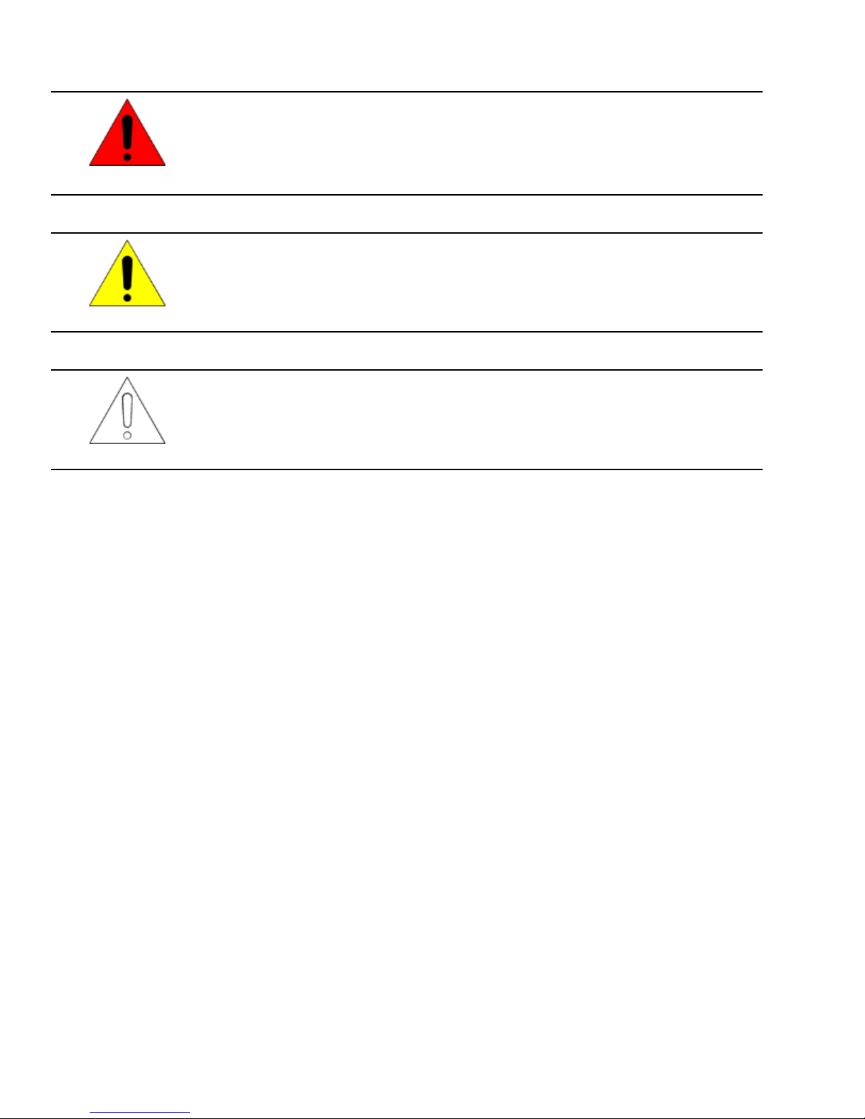
Safety Symbol Legend
Indicates a procedure, condition, or statement that, if not strictly observed, could result in
personal injury or death.
Warning
Indicates a procedure, condition, or statement that, if not strictly observed, could result in
damage to or destruction of equipment.
Caution
Indicates a procedure, condition, or statement that should be strictly followed to improve
these applications.
Attention
For public disclosure
Page 5

Contact Information
If you purchased this product through an Authorized Channel Partner, then contact the seller directly.
General Contact Information
Online technical support and GlobalCare http://support.ge-ip.com
Additional information http://www.ge-ip.com/
Solution Provider solutionprovider.ip@ge.com
Technical Support
If you have technical problems that cannot be resolved with the information in this manual, please contact us by
telephone or email, or on the web at http://support.ge-ip.com
Americas
Online Technical Support http://support.ge-ip.com
Phone 1-800-433-2682
International Americas Direct Dial
Technical Support Email support.ip@ge.com
Customer Care Email
Primary language of support English
1-780-420-2010 (if toll free 800 option is unavailable)
customercare.ip@ge.com
Europe, the Middle East, and Africa
Online Technical Support http://support.ge-ip.com
Phone + 800-1-433-2682
EMEA Direct Dial
Technical Support Email support.emea.ip@ge.com
Customer Care Email
Primary languages of support English, French, German, Italian, Czech, Spanish
+ 420-23-901-5850 (if toll free 800 option is unavailable or dialing from
a mobile telephone)
customercare.emea.ip@ge.com
Asia Pacific
Online Technical Support http://support.ge-ip.com
Phone
Technical Support Email
Customer Care Email
+ 86-400-820-8208
+ 86-21-3217-4826 (India, Indonesia, and Pakistan)
support.cn.ip@ge.com (China)
support.jp.ip@ge.com (Japan)
support.in.ip@ge.com (remaining Asia customers)
customercare.apo.ip@ge.com
customercare.cn.ip@ge.com (China)
For public disclosure
GFK-2898B 5
Page 6

Notes
6 GFK-2898B PACSystems 19" RXi Display
For public disclosure
Page 7

Contents
1 Overview ............................................................................................................................................. 9
1.1 Specifications .. ....................... .............................................. .............................................. .................. 11
1.1.1 General Specifications .................. ....................... ....................... .............................................. ....... 11
1.1.2 Display Specifications................................. .............................................. ..................... .................. 12
1.1.3 Environmental Specifications .............................. .............................................. ..................... ........... 13
1.2 User Features................... .............................................. .............................................. ..................... .... 14
1.2.1 Power On/Off and User-defined Buttons..................................... .............................................. ........... 16
1.2.2 Status Indicators ................................... .. ..................... .............................................. ..................... 17
1.2.3 Ethernet Port LEDs .......................................... ..................... .. .............................................. .......... 17
1.2.4 SD Card Slot ..................................... .............................................. .. ..................... ....................... . 17
1.2.5 Backlight Control........................ ................................................................... .. ............................... 17
2 Pre-Installation Checks and Initial Startup .............................................................................. 19
2.1 Unpacking and Inspection ........ .............................................. .. ..................... .......................................... 19
2.2 Initial Startup................... ..................... .............................................. .............................................. .... 20
2.3 Configuring Ethernet Network Communications .. .............................................. .......................................... 22
2.3.1 Pinging TCP/IP Ethernet Interfaces on the Network....... ..................... .. .............................................. ... 22
2.3.2 Determining if an IP Address is Already In Use . ....................... .............................................. .............. 22
2.4 Shutting Down the Computer .................. ..................... .. .............................................. ..................... ....... 23
2.4.1 Disabling Operating System Shutdown ..................... .............................................. ............................ 24
3 Hardware Installation .................................................................................................................... 25
3.1 Mounting and Installation Guidelines .............................................. .. ..................... ................................... 25
3.2 Grounding..... .............................................. .............................................. ....................... .................... 25
3.3 Mounting and Installation........................ .............................................. .............................................. .... 26
3.3.1 Removal............................. .............................................. ....................... ....................... ............... 27
4 Service and Maintenance ............................................................................................................. 29
4.1 Real Time Clock Battery Replacement................. .............................................. .. ...................................... 29
4.2 Disabling the Off Button ................................ .............................................. ....................... .................... 32
5 Connectors and Cabling............................................................................................................... 33
5.1 Input Power ....................... ....................... .............................................. .............................................. 33
5.2 Ethernet Communication Ports ............................................. ....................... ....................... ...................... 34
5.2.1 Ethernet Media ............................................. .............................................. ....................... ............. 34
5.3 Serial Communication Port..................... ..................... .. .............................................. ............................ 35
5.4 USB Ports ........................................... .. ............................................ .. ..................... ............................ 36
5.5 Video Output Port ............................. .. ..................... .............................................. ................................ 37
5.6 Secure Digital Card Slot..... .............................................. .............................................. ..................... .... 37
5.7 Audio Jack ................................ .............................................. ..................... .. ...................................... 37
6 System Recovery............................................................................................................................39
6.1 Drive Failure Recovery............................................ .............................................. .. ..................... .......... 39
6.2 Overtemperature Shutdown Recovery (All Models)............... ..................... .............................................. .... 39
Appendix A Certifications and Installation Guidelines............................................................... 41
Agency Approvals and Standards............................... ..................... .. .............................................. .......... 41
Waste Disposal ......................................... ....................... ....................... ....................... ................. 41
EMC Standards ............................................ ..................... .............................................. .. ............. 42
For public disclosure
GFK-2898B 7
Page 8

Government Regulations ............................... .. ................................................................... ..................... 43
Index......................................................................................................................................................... 45
8 GFK-2898B PACSystems 19" RXi Display
For public disclosure
Page 9
1 Overview
The PACSystems* RXi product line of industrial computers provides an advanced,
high-performance control and computing platform. The PACSystems RXi Box Industrial
PC (IPC) delivers the flexibility of a computer with the industrial ruggedness of
traditional automation controllers. Built with an open and scalable architecture, the RXi
platform enables easy connectivity and allows you to maximize application reusability—
supporting your current and future needs for business growth. These small form factor
IPCs provide a number of features to support computing applications in demanding
environments, including:
• Dual core 1.0 GHz VIA processor
• Multiple Gigabit Ethernet interfaces provide network implementation flexibility.
• Built-in data storage – Internal disks provide highly reliable local long-term data
• USB and Secure Digital (SD) card interfaces enable program loading, serial
The PACSystems 19” RXi Display with widescreen LCD display and projected capacitive
multi-touch touchscreen brings the latest in high-performance computing technology
capable of withstanding the requirements of industrial environments to the industrial HMI
space. The RXi Display incorporates RXi Box IPC processor hardware to create a system
that lowers total cost ownership with seamless replacement of either the processor or
display component, and provides for powerful upgrades to the underlying computing
technology. The RXi Display can be mounted directly into an industrial panel.
retention.
communications and removable data storage through standard devices.
The RXi Display is a 1 GHz x86–64 based fanless computing platform with a 19” display
and a high quality touch-based operator interface enclosed in an aluminum enclosure,
combining both ruggedness and longevity. The 10.16 mm (0.4 in) depth to the panel
provides a sleek design. The touchscreen offers superior abrasion resistance, transmissive
clarity, and unsurpassed touch sensitivity. Display mounting and installation only requires
a single person. The RXi Display offers a 1 GHz Windows
two GigE ports, two USB 2.0 ports, one serial COM port, a Secure Digital (SD) card slot,
and an additional video graphics array (VGA) port.
Ordering Information
Part Number Description
ICRXIDIXNE19LCTA RXi 19” Display with Embedded 32 GB mSATA SSD and Windows 7 Professional, SP1
ICRXIDIXNM19LCTA RXi 19” Display with 250 GB Magnetic SATA Hard Drive and Windows 7 Professional, SP1
ICRXIDI0NE19LCTA 19” RXi Display with 32 GB mSATA SSD, No Operating System
ICRXIDI0NM19LCTA 19” RXi Display with 250 GB SATA HDD, No Operating System
IC690ACC001 Real Time Clock (RTC) battery, included with RXi Display
©
7 64-bit-based platform with
Overview GFK-2898B 9
For public disclosure
Page 10
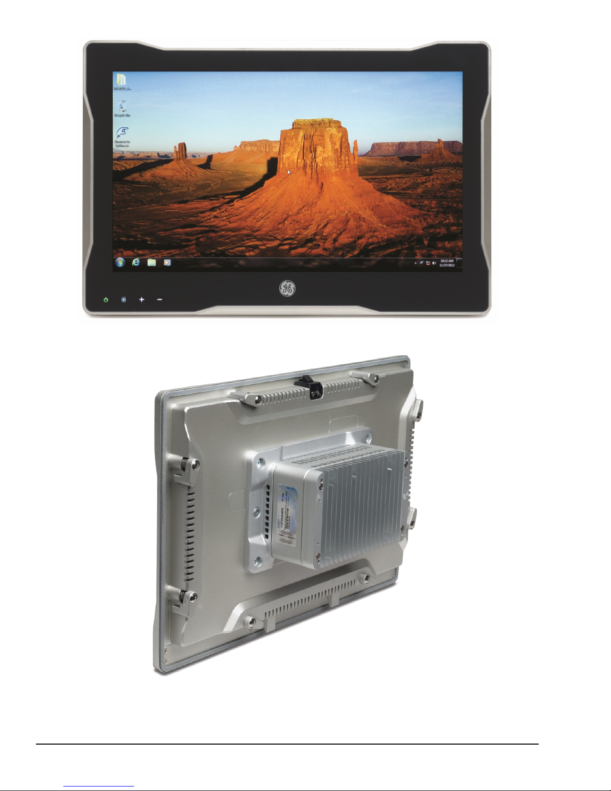
19" RXi Display (Front View)
10 GFK-2898B PACSystems 19" RXi Display
For public disclosure
19" RXi Display (Rear View)
Page 11

1.1 Specifications
479.4 mm
(18.9 in)
323 mm
(12.7 in)
116.9 mm
(4.6 in)
41.8 mm
(1.7 in)
SD Card Slot
1.1.1 General Specifications
Item
Dimensions 323 x 479.4 x 116.9 mm (12.7 x 18.9 x 4.60 in)
Weight 7 kg (15 lb)
Processor
RAM 4 GB DDR3
Floating point
Non-volatile storage
Time of day clock (RTC)
accuracy
Video
Maintenance ports
(Intended only for temporary
connection)
Power requirements
Serial Communications
Ethernet Communications
Specification
1.0 GHz VIA Eden dual core processor
64–bit
32 GB mSATA SSD or 250 GB SATA HDD
Non-volatile storage (NVS) can retain data indefinitely without loss of data integrity.
Maximum drift of ±2 seconds/day at 25°C (77 °F)
Standard 15-pin VGA connector
Two Type A USB 2.0
SD standard card slot
Dual function Audio OUT/Microphone IN jack (3.5 mm four-pin TRRS)
2.6 A at 24 V dc (18 to 32 V dc)
LPS or Class 2 power supply required
One RS-232 RJ-45 port
Two Ethernet (10, 100, 1000 Mbit/s) RJ-45 ports
Overview GFK-2898B 11
For public disclosure
Page 12

1.1.2 Display Specifications
Item
Display
Type
Screen Diagonal/Aspect Ratio 470.1 mm (18.5 in) / 16:9
Image Size 409.8 mm (16.1 in) horizontal (H) x 230.4 mm (9.1 in) vertical (V)
Native Resolution
Pixel Pitch
Number of Colors
Brightness ≥ 300 nits (cd/m
Viewing Angle
Contrast Ratio
Backlight/Brightness Half-life
Touchscreen
Cover Glass Hardness 9H
Cover Glass Compressive Strength
Electrical
Grounding Frame ground (FG) internally connected to signal ground
Physical
Material Aluminum bezel
Enclosure Rating UL/NEMA Type 1
Depth to Panel <10.16 mm (0.4 in)
Panel Cutout Dimensions
Panel Thickness
Minimum Clearances around RTM
Feature
LED Indicators
ON/OFF Button
User-defined Buttons
Backlight Enable Integrated with operating system
Backlight Dimming Integrated with operating system
Specification
TFT-LCD
1366 H x 768 V pixels WXGA
0.300 mm (0.012 in)
16.7 M (RGB 6-bits + Hi-FRC data)
2
)
H: 170° typical
V: 160° typical
600 min/1000 typical
LED/50,000 hours
Projected capacitive multi-touch (2-touch)
≥ 400 MPa
457 x 292 mm (18 x 11.5 in)
1.5875 to 4.7625 mm (0.0625 to 0.1875 in)
Each side: 51 mm (2 in)
Top and bottom: 127 mm (5 in)
Wi-Fi, Bluetooth, Wireless Wide Area Network (WWAN), disk activity,
over-temperature
Capacitive-touch and multi-color LED indicator
Capacitive-touch and LED indicators (Qty 3)
12 GFK-2898B PACSystems 19" RXi Display
For public disclosure
Page 13

1.1.3 Environmental Specifications
The RXi Display should be installed in a location
that is not exposed to corrosive gases or liquids,
rain, or direct sunlight, and that meets the
environmental specifications listed in the following
Caution
Note For additional product standards and agency approvals, refer to Appendix A.
table.
Item
Cooling
Vibration Operating
Shock Operating
Ambient Operating
Temperature
Storage Temperature
Humidity
Altitude UL 60950-1
Environment
1
Applies only to 19” Displays with solid state hard drive.
2
For ambient temperatures greater than 50°C (122 °F), the unit must be installed in a restricted access area as defined in this
document.
1
2
Standard
N/A
1
IEC60068-2-6
IEC60068-2-27
N/A
N/A
N/A
UL 60950-1 Pollution Degree 2
Description
Natural convection
(Sine): 10 - 57 Hz, 0.152 mm (0.006 in) displacement peak-peak
57 - 500 Hz, 1.0 g acceleration
(Half-sine) 15 g pk, 11 ms
0 to 60°C (32 to 140 °F) (SSD)
0 to 40°C (32 to 104 °F) (HDD)
-20 to 60°C (-4 to 140 °F)
10 to 85% non-condensing
0 to 2,000 m (0 to 6,562 ft)
This applies where there is only non-conductive pollution that might temporarily
become conductive due to occasional condensation.
If the RXi Display is operating in ambient
temperatures greater than 50°C (122 °F), its exterior
temperatures may be too hot to touch safely. To
avoid burn hazards, the unit must be installed in a
restricted access area, as defined by:
Overview GFK-2898B 13
For public disclosure
Warning
Caution
•• Access can only be gained by service persons or by
users who have been instructed about the reasons
for the restrictions applied to the location and about
any precautions that shall be taken; and
•• Access is through the use of a tool or lock and key,
or other means of security, and is controlled by the
authority responsible for the location.
EMC Requirements:
When installing, operating, or maintaining the RXi
Box IPC, personnel must ensure that any
electrostatic charge is discharged using a grounded
Electrostatic Discharge (ESD) strap or other means.
Page 14

1.2 User Features
The 9H hardness flat surface cover glass provides a gapless surface that is easy to clean,
with superior abrasion resistance, transmissive clarity, and unsurpassed touch sensitivity.
Mount the RXi Display on a flat surface in a UL/NEMA Type 1 enclosure that protects
against incidental contact and falling dirt. The following RXi display features are
accessible on the front of the panel:
• Multi-touch projected capacitive touchscreen
• 16:9 wide format TFT LCD display
• Power on/off and three user-defined capacitive touch buttons with LED indicators
• Status indicators for disk activity and over-temperature
• Status indicators for Wi-Fi, Bluetooth, and WWAN connectivity (from optional
• SD card slot
Note Status indicators are hidden on the display until they show activity.
Note When the SD card is not installed, a rubber cover is provided to keep out liquids.
The following features are internal or accessible from the rear of the panel:
mPCIe card)
• IPC connectors
• Internal SATA drive (2.5 in)
• External 3-pin modular 24 V dc power supply connector
14 GFK-2898B PACSystems 19" RXi Display
For public disclosure
Page 15
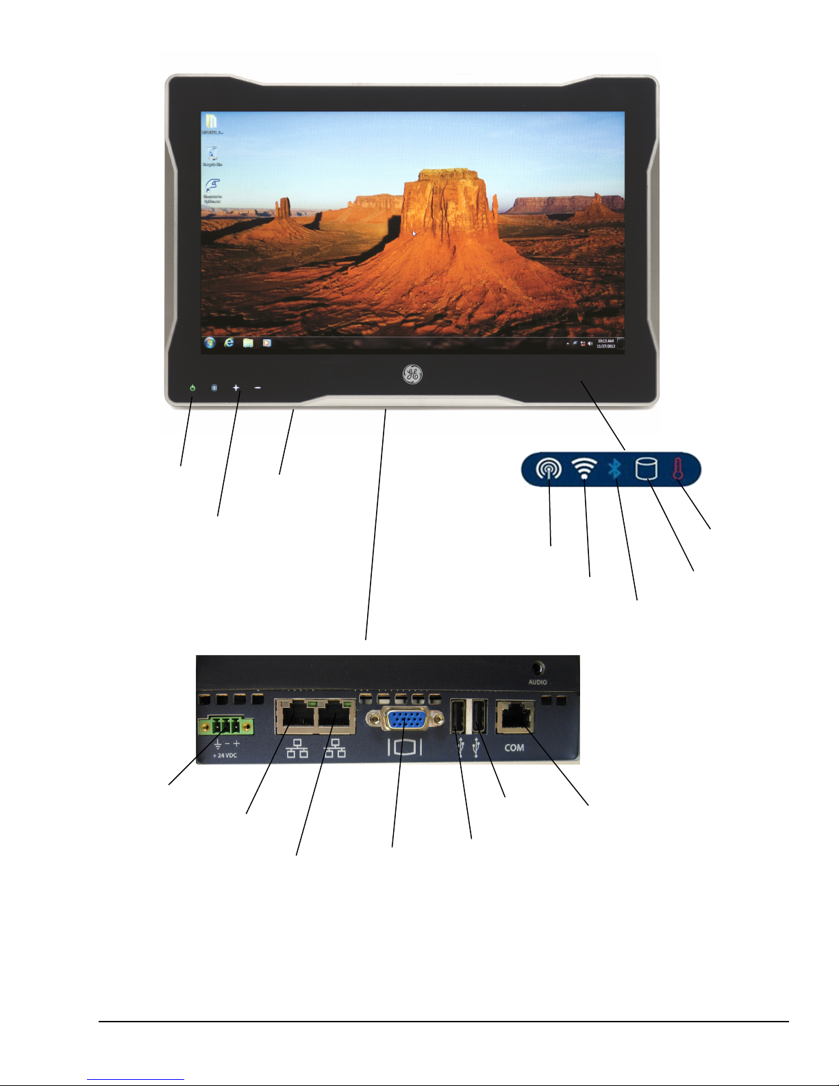
SD Card Slot
User-defined
Menu
Plus
Minus
Power On/Off
Overtemp
SATA Drive
Activity
Bluetooth
Wi-Fi
WWAN
Input Power
Ethernet 1
Ethernet 2
VGA
USB 1
USB 2
Serial RS-232
Connector Panel
Overview GFK-2898B 15
For public disclosure
RXi Display Features
Page 16

1.2.1 Power On/Off and User-defined Buttons
Power On/Off Button Operation
Button
Power on
Power off
†
Touch the button for at least ½ second.
If powering up after input power has been restored, the LED blinks blue
while the unit is booting and is solid green when the unit is up and running.
If the system has been shut down, and input power not removed, the LED
immediately turns solid green.
Touch the button briefly (between 100 ms and 4 seconds).
The LED remains green while the unit is shutting down and displays as
white when the unit is powered down.
Touch the button for at least 4 seconds. The LED turns white when the unit
is powered down.
Action
Force
shutdown
Use this option only if the
operating system is
non-responsive.
Caution
†
The LED displays solid red to indicate a fault, including over-temperature condition.
User-defined Button and LED Operation
Button
Menu
Plus
Minus
User-defined button and white LED.
GE-IP FpBtn driver illuminates LED and allows user to select
Windows application to open or keycode to select when button
touched.
Operation
16 GFK-2898B PACSystems 19" RXi Display
For public disclosure
Page 17

1.2.2 Status Indicators
Activity
LED
Link
LED
Indicator State
SATA Drive Status
White, blinking
Over-temperature
Bluetooth
Wi-Fi
WWAN
Red, solid
Blue, solid
White, solid
White, solid
Description
Read/write access on SATA drive
Internal temperature has exceeded the maximum
allowable value. The unit will shut down.
To recover, let the unit cool, then touch the Power
On/Off button.
Bluetooth connected (optional mPCIe card)
Connected to wireless network
(optional mPCIe card)
Connected to WWAN (optional mPCIe card)
1.2.3 Ethernet Port LEDs
Each Ethernet port has two LED indicators, ACTIVITY and LINK.
LED Status
Description
Activity
Link
Indicator State
Green,
blinking
Green, on
solid
Traffic is detected at the port
Link is operational
1.2.4 SD Card Slot
The display accommodates a user-supplied SD card for auxiliary storage. The
front-mounted SD card slot can be accessed without opening the enclosure.
1.2.5 Backlight Control
The LCD display’s LED backlight can be enabled and backlight brightness controlled by
the operating system.
Overview GFK-2898B 17
For public disclosure
Page 18

Notes
18 GFK-2898B PACSystems 19" RXi Display
For public disclosure
Page 19

2 Pre-Installation Checks and Initial
Startup
Before installing and using the RXi Display, complete the following steps:
• Unpacking and inspection
• Initial startup
• Configuring Ethernet communications
2.1 Unpacking and Inspection
Do not apply power to the unit if it has visible
damage. Applying power to a unit with damaged
components may cause additional damage.
Caution
Upon receiving the RXi Display, carefully inspect all shipping containers for damage. If
any part of the system is damaged, notify the carrier immediately. The damaged shipping
container should be saved as evidence for inspection by the carrier.
For phone numbers and email
addresses, refer to the section
Contact Information.
As the consignee, it is your responsibility to register a claim with the carrier for damage
incurred during shipment. However, we will fully cooperate with you should action be
necessary.
After unpacking the RXi Display, record all serial numbers. Serial numbers are required
if you need to contact Customer Care during the warranty period. All shipping containers
and packing material should be saved should it be necessary to transport or ship any part
of the system.
Verify that all components of the system have been received and they agree with your
order. If not , contact Customer Care. For technical help, contact Technical Support.
Before attempting to power up the RXi Display for the first time, inspect the unit for
loose or damaged components. If damage is observed (such as bent component leads or
loose components), contact GE Intelligent Platforms. Depending on the severity of the
damage, it may be necessary to return the product to the factory for repair.
Pre-Installation Checks and Initial Startup GFK-2898B 19
For public disclosure
Page 20

2.2 Initial Startup
The following equipment and tools are needed for initial startup:
• 24 V dc, 18 – 32 V range, 65 W power supply
• Power cord with 24 –16 AWG wires; user calculates proper wire gauge according to
• One small blade flat-head screwdriver for M2 and M2.5 machine screws
• USB-compatible keyboard (optional)
• USB-compatible mouse (optional)
The power supply used should be a UL listed
power source providing voltage isolation with a
SELV output, or a Class 2 power source. A
readily accessible disconnect device shall be
Warning
Note The product is supplied with a Phoenix Contact part number 1827716 power
terminal block plug. Phoenix Contact part number 1851245 (spring loaded/quick
release) power terminal block plug may also be used.
local regulations
incorporated in the building installation wiring.
20 GFK-2898B PACSystems 19" RXi Display
For public disclosure
Page 21

➢➢ To initially start up the RXi Display
FGND
O V +24 V
1. Attach the power supply output to the RXi Display’s dc power plug using 16 – 24 AWG
2
(1.31– 0.20 mm
(1.31 mm
2
cross section) wire. For frame ground, use shortest length 16 AWG
) wire to ground. The recommended wire stripping length is 7 mm (0.28 in).
Tighten the screws that hold the wires to a torque of 0.452 Nm (4 in-lb).
2. Insert the plug into the RXi Display’s input power connector and securely tighten the
attaching screws. The torque range for the attaching screws is 0.452 Nm (4 in-lb). (For
proper grounding, refer to the section Grounding.)
3. (Optional) If desired, attach a USB-compatible keyboard and a USB-compatible mouse.
4. Power up the unit and check for any concealed damage that may have been caused by
incorrect transportation, operating/storage conditions or handling. To power up the unit,
touch Power On/Off for at least ½ second.
If you notice any damage, remove power from the
unit immediately and secure it against unintentional
use.
Caution
During power up, you should see the normal operating system starting displays on the
monitor. During normal power up and operation, the Power On/Off status indicator displays
as follows:
For model numbers, refer
to the table Ordering
Information.
Power On/Off LED Status Indicator
LED Description
Solid white RXi Display is off
Blinking blue RXi Display is turned on after input power is restored
Solid green RXi Display has completed startup and is running
Solid green RXi Display is turned on without input power loss
5. For models loaded with Windows 7 Professional, the operating system starts
automatically. During startup, the operating system splash screen displays on the monitor.
To activate the operating system, follow the on-screen prompts. The Windows 7 product
key is on the Microsoft Certificate of Authenticity label, which is on the side of the RXi
Display.
To activate the operating system online, configure the RXi Display’s Ethernet settings for
operation on your network.
Note For models without an operating system, two hard drive options are available: a
blank 32 GB mSATA SSD or a blank 250 GB SATA magnetic HDD. Load the desired
operating system and associated drivers to fully use the I/O interfaces.
Pre-Installation Checks and Initial Startup GFK-2898B 21
For public disclosure
Page 22

2.3 Configuring Ethernet Network Communications
The default factory settings are
configured to obtain an IP
address automatically.
For Ethernet port and cabling
information, refer to Chapter 4
Connectors and Cabling.
Before configuring the RXi Display for operation on a network, consult your network
administrator. Duplicate TCP/IP addresses and duplicate computer names on the same
network can cause network problems.
➢➢ To configure Ethernet communications
1. For both ports, if necessary, use the operating system’s network configuration tool to
change the IP address and subnet mask from the factory settings to the correct
settings for your network. If your network's IP addresses are controlled by a Dynamic
Host Configuration Protocol (DHCP) server, change the setting from Use the
following IP address to Obtain an IP address automatically.
Ethernet Ports
Port Network Adapter Name
Ethernet 1 VIA Velocity
Ethernet 2 Intel 82574L
2. When prompted by the operating system, restart the RXi Display.
3. Connect the RXi Display to the Ethernet network.
2.3.1 Pinging TCP/IP Ethernet Interfaces on the
Network
Most nodes on TCP/IP networks, including the PACSystems Ethernet interface,
implement a PING command. Ping each installed Ethernet device. When the Ethernet
device responds to the ping, it verifies that the device is operational and configured
properly.
2.3.2 Determining if an IP Address is Already In Use
This method does not guarantee that an IP address is not duplicated. It will not detect a
device that is configured with the same IP address if it is temporarily off the network.
It is very important not to duplicate IP addresses.
Attention
➢➢ To determine if another node on the network is using the same IP
address
1. Disconnect your RXi Display from the LAN.
2. Ping the disconnected RXi Display IP address.
If you get an answer to the ping, the chosen IP address is already in use by another
node. Correct this situation by assigning a unique IP address.
22 GFK-2898B PACSystems 19" RXi Display
For public disclosure
Page 23

2.4 Shutting Down the Computer
To avoid damaging files, always shut down Windows
software before removing power from the RXi
Display.
Caution
Do not disconnect external devices, such as a flash
drive or external DVD drive without first using the
Windows Safely Remove Hardware feature to eject
the device. Failure to observe this precaution could
result in damage to data.
Refer to the table Power
On/Off LED Status Indicator.
Caution
➢➢ To shut down the RXi Display
1. Touch Power On/Off briefly (between 100 ms and 4 seconds), or select Shut
Down from the Windows Start menu. This provides a controlled shutdown of the
operating system before removing power from the system. The status indicator
remains solid green while the RXi Display is shutting down and then turns white
when the RXi Display has finished powering down.
2. To completely shut down the RXi Display, turn off or remove the power supply to the
RXi Display.
Pre-Installation Checks and Initial Startup GFK-2898B 23
For public disclosure
Page 24

2.4.1 Disabling Operating System Shutdown
The current On/Off button operation requires a touch of approximately 100 ms to begin a
controlled Windows shut down. You can change this setting in Windows to require
touching the On/Off button for 4 seconds to immediately perform a hard shutdown that
forces the unit off without first shutting down Windows. This provides some protection
against unplanned shutdowns caused by accidentally touching the button. If a hard
shutdown is acceptable, change the Off button touch-time to 4 seconds using Windows 7
settings.
➢➢ To change the Off button touch-time using Windows
1. From the Start menu, select Control Panel.
2. Select Hardware and Sound section (if displayed).
3. Select Power Options.
4. Select Choose what the power buttons do.
5. Change the When I press the power button selection to Do Nothing.
6. Save the changes.
Note To completely disable the power off function, set a switch that is located inside the
RXi Display. This disables the ability to shut down the RXi Display using the On/Off
button and prevents unplanned shutdowns that may be caused by accidentally touching
the On/Off button. Refer to the section Disabling the Off Button.
24 GFK-2898B PACSystems 19" RXi Display
For public disclosure
Page 25

3 Hardware Installation
3.1 Mounting and Installation Guidelines
The RXi Display is mounted directly onto a panel or enclosure. (Refer to the section
Mounting and Installation.) Adhere to the following guidelines for mounting and
installation:
• The RXi Display should be mounted on a flat surface in a UL/NEMA Type 1
enclosure.
• The RXi Display must be mounted with its cooling fins vertical to ensure adequate
air flow. Mounting orientation is permitted only with connectors oriented down.
• The panel should be capable of supporting the weight of the RXi Display without
distortion to the panel.
• Adequate air flow around the exterior of the unit is essential to maintain safe interior
temperature of the unit. Inlets and outlets must not be obstructed. (Refer to the table
Display Specifications.)
• You may need to allow more space for installation of cables and connectors than
what is required for heat dissipation. To avoid impacting mechanical reliability and
signal quality, cable installation must comply with the minimum bend radius
specified by the cable manufacturer.
3.2 Grounding
The following guidelines apply for proper grounding:
Note These grounding connections serve as a path for reducing noise interference and
radiated emissions and are required for the RXi Display to comply with the standards
identified in Appendix A.
• The RXi Display chassis requires a safety ground connection to protective earth. This
ground wire shall be at least 16 AWG (1.31 mm
short as possible. When mounting the RXi Display, add the ground wire underneath
either of the two center screws attaching the RTM assembly to the display panel, and
connect to protective earth.
• The frame ground connection on the power plug should be a 16 AWG (1.31 mm
cross section) wire with shortest possible length. It is recommended that both ground
wires terminate in a star wiring pattern at the same grounding point, and connect to
protective earth.
2
cross section) and should be as
2
Hardware Installation GFK-2898B 25
For public disclosure
Page 26

3.3 Mounting and Installation
The RXi Display is installed as a panel mounted operator interface. One person can install
the display without the use of any special tools.
Caution
Attention
➢➢ To install the display panel
1. Check the bezel gasket for damage, and replace if necessary.
2. Swing the eight levers on the back of the RXi Display to their retracted position, held
in place by a ball plunger.
Mount the RXi Display on a flat surface in a
UL/NEMA Type 1 enclosure.
The cooling fins on the back of the RXi Display must
be vertical. The unit can only be mounted with the
front display connectors oriented down.
3. From the front of the enclosure, tilt the RXi Display into the enclosure opening and
rest its two lower brackets on the enclosure opening bottom edge.
4. Push the top of the RXi Display towards the enclosure until the top latch catches the
enclosure opening top edge.
5. Swing out the eight levers to rest against the enclosure wall.
6. Using a #2 Phillips screwdriver, tighten the lever screws to 0.79 Nm (7 in-lb) using
the tightening order illustrated in the following figure.
26 GFK-2898B PACSystems 19" RXi Display
For public disclosure
Page 27

8 3
5
2
1
6
4
7
Lever Screw Tightening Order
3.3.1 Removal
➢➢ To remove the RXi Display
1. Using a #2 Phillips screwdriver, loosen the lever screws.
2. Swing the eight levers on the back of the RXi Display to their retracted position, held
in place by a ball plunger.
Be careful to not drop the unit when tilting it
forward to remove it from the enclosure.
3. Insert a thin blade from the front between the gasket and panel wall at the top center
4. Tilt the RXi Display forward and remove it from the front of the enclosure.
Caution
location to depress the latch.
Hardware Installation GFK-2898B 27
For public disclosure
Page 28

Notes
28 GFK-2898B PACSystems 19" RXi Display
For public disclosure
Page 29

4 Service and Maintenance
Risk of Fire — there are no user-serviceable fuses in
the RXi Display.
Warning
4.1 Real Time Clock Battery Replacement
The Real Time Clock (RTC) is backed up by a lithium coin cell battery, IC690ACC001.
The RTC battery has an estimated life of 5 years.
The following tools are needed to replace the RTC battery:
• One #2 Phillips screwdriver
• Battery (part number IC690ACC001)
The replacement battery must be IC690ACC001
from GE Intelligent Platforms. Using a different
battery type than specified may present a high risk
Warning
of fire or explosion.
Warning
Caution
The battery may explode if mistreated. Do not
recharge, disassemble, heat above 100°C (212° F), or
incinerate.
To avoid damage from electrostatic discharge,
adhere to the following precautions when opening
the RXi Display:
1) Wear a properly functioning antistatic strap and
be sure that you are fully grounded. Never touch
any components inside the RXi Display unless you
are wearing an antistatic strap.
2) The RXi Display should be placed on a static-safe
surface, facilitated by antistatic mats.
3 ) Extra caution should be taken in cold, dry
weather, when static charges can easily build up.
Service and Maintenance GFK-2898B 29
For public disclosure
Page 30

➢➢ To replace the RTC battery
RTC Battery
1. Remove power from the RXi Display by disconnecting the power cable.
2. Loosen the six captive screws on the back of the RXi Display that are holding the
RTM and gently lift the RTM away from the display panel.
3. Loosen the four captive screws that are holding the two RTM sections together and
gently separate without stretching the internal power cable. Disconnect the internal
power cable and place the RTM chassis with interior lid on a static-safe surface.
4. Remove the four Phillips-head screws that secure the interior lid to the RTM chassis,
and lift off the interior lid.
5. Remove the RTC battery from the retaining clip. Do not use any metallic item to
remove the battery, including screwdrivers, knives, pliers, and such.
Be careful to not bend the positive terminal clip on
the battery holder.
Caution
Dispose of used batteries in accordance with the
instructions provided in the Battery Disposal
document, 82A1540-MD01.
Attention
30 GFK-2898B PACSystems 19" RXi Display
For public disclosure
RTC Battery Location
Page 31

6. Install the replacement battery (IC690ACC001) in the retaining clip with the positive
(+) side up. That is, with the + side away from the circuit board. The coin cell must
be inserted at an angle to go under the positive terminal clip and then slid into the
carrier and snapped into place.
7. Replace and secure the interior lid using four Phillips-head screws.
8. Reconnect the internal power cable.
9. Reattach the two RTM sections together without pinching the internal power cable,
and tighten the four captive screws to secure them.
10. Carefully align the RTM to the display panel and push until the connector is seated.
11. Tighten the six captive screws to fasten the RTM.
Service and Maintenance GFK-2898B 31
For public disclosure
Page 32

4.2 Disabling the Off Button
SW1-1 Switch
Shown in the default (Off) position
Disable powering off using the On/Off button by changing the setting of SW1-1, which is
located on the display mounting adapter. This prevents unplanned shutdowns caused by
accidentally touching the On/Off button.
Note The disabled setting affects only the ability to power down the unit. You can still
use the On/Off button to power on the unit.
This procedure requires the use
of one #2 Phillips screwdriver.
➢➢ To disable the Off button
1. Disconnect the power cable to remove power from the RXi Display.
2. Loosen the six captive screws on the back of the RXi Display that are holding the
RTM and gently lift the RTM away from the display panel.
3. Loosen the four captive screws that are holding the two RTM sections together and
gently separate without stretching the internal power cable. Disconnect the internal
power cable and place the RTM section containing a circuit board with switch SW1
facing up on a static-safe surface.
4. Remove the tape covering SW1, if present, and move the SW1-1 switch from the
default (Off) position to the On position.
5. Reconnect the internal power cable.
6. Reattach the two RTM sections together without pinching the internal power cable,
and tighten the four captive screws to secure them.
7. Carefully align the RTM to the display panel and push until the connector is seated.
8. Tighten the six captive screws to fasten the RTM.
32 GFK-2898B PACSystems 19" RXi Display
For public disclosure
Page 33

5 Connectors and Cabling
This chapter describes the connector layout and cabling requirements on the RXi Display,
as well as power and communication connectors. All connectors except the SD card
interface are provided on the bottom panel of the RXi Display.
Summary of Cabled Ports
Port Name
24 V dc Permanent
Ethernet 1 Permanent
Ethernet 2 Permanent
Serial RS-232 Permanent
USB 1 Maintenance
USB 2 Maintenance
VGA Video Maintenance
SD Card slot Maintenance
Audio Maintenance
1
Shielding is required to be in compliance with the standards identified in Appendix A.
2
Can be permanently connected while the system is running
3
Intended only for temporary connection
Usage
2
2
2
2
3
3
3
3
3
Recommended Max
Cable Length
3 m (9.8 ft)
100 m (328 ft)
100 m (328 ft)
10 m (32.8 ft)
5 m (16.4 ft)
5 m (16.4 ft)
7.6 m (25 ft)
N/A N/A
2 m (6.5 ft)
Shielding
Required
No
1
Yes
1
Yes
1
Yes
1
Yes
1
Yes
1
Yes
No
5.1 Input Power
To connect the dc power
supply, refer to the section
Initial Startup.
The RXi Display requires the following power input power connection:
• 24 V dc, 18 – 32 V range, 65 W power supply
The power supply used should be a UL listed
power source providing voltage isolation with a
SELV output, or a Class 2 power source. A
readily accessible disconnect device shall be
Warning
incorporated in the building installation wiring.
Note The RXi Display is supplied with a Phoenix Contact part number 1827716
power terminal block plug. Phoenix Contact part number 1851245 (spring
loaded/quick release) power terminal block plug may also be used.
• Power cord with 24 –16 AWG wires; user calculates proper wire gauge according to
local regulations
Connectors and Cabling GFK-2898B 33
For public disclosure
Page 34

5.2 Ethernet Communication Ports
Activity LED
Link LED
Pin 1
The RXi Display provides two RJ-45 Ethernet network port connectors that support
10BASE-T, 100BASE-TX and 1000BASE-T communications. Either or both of these
ports may be attached to other Ethernet devices. Each port automatically senses the data
rate (10, 100 or 1000 Mbps), duplex (half duplex or full duplex), and cabling
arrangement (straight through or crossover) of the attached link.
The two ports on the Ethernet Interface must
not be connected, directly or indirectly to the
same device. The hub or switch connections in
an Ethernet network must form a tree,
Caution
5.2.1 Ethernet Media
otherwise duplication of packets may result.
For operation of the Ethernet
port LED indicators, Activity
and Link, refer to the section
Ethernet Port LEDs.
The RXi Display can operate on 10BASE-T, 100BASE-TX or 1000BASE-T media
through its network ports. All three arrangements can use up to 100 m (328 ft) of
Category 5e twisted pair cable between each node and a switch, hub, or repeater.
For all three types, shielded twisted pair (STP) cable
is required to maintain CE compliance.
Attention
10BASE-T: Two pairs of wire are used, one for transmission, and the other for receive.
100BASE-TX: Two pairs of wire are used, one for transmission, and the other for
receive.
1000BASE-T: Four pairs of wire are used for simultaneous transmission and receive in
both directions.
Ethernet Port Pin Assignments
10BASE-T/100BASE-TX 1000BASE-T
Pin #
Signal Description Signal Description
1 TD+ Transmit Data +
2 TD- Transmit Data –
3 RD+ Receive Data +
4 NC No connection
5 NC No connection
6 RD- Receive Data –
7 NC No connection BI-DD+
8 NC No connection
BI_DA+ Bidirectional pair A+
BI_DA- Bidirectional pair A-
BI_DB+ Bidirectional pair B+
BI_DC+ Bidirectional pair C+
BI_DC- Bidirectional pair C-
BI_DB- Bidirectional pair B-
BI_DD- Bidirectional pair D-
Bidirectional pair D+
Note Pin assignments are provided for diagnostic purposes only. Ethernet cables are
readily available from commercial distributors. We recommend purchasing rather than
making cables.
34 GFK-2898B PACSystems 19" RXi Display
For public disclosure
Page 35

5.3 Serial Communication Port
For maximum cable length,
refer to the table Summary of
Cabled Ports.
The serial port provides RS-232 communications through a standard RJ-45 female
connector with the following pin assignments.
Shielded cable is required to maintain CE
compliance.
Attention
Serial RS-232 Port Pin Assignments
RJ-45 Pin # Signal Description
8 0 V 0 V
7
6 NC No connection
5 0 V 0 V
4 NC No connection
3 Rx Receive
2 NC No connection
1 Tx Transmit
NC No connection
Connectors and Cabling GFK-2898B 35
For public disclosure
Page 36

5.4 USB Ports
Pin 1
For maximum cable length,
refer to the table Summary of
Cabled Ports.
Two ports are provided for connection of USB 2.0 compatible devices, such as a
keyboard, mouse, serial communications or data storage device.
Double-shielded cable that complies with USB 2.0 is
required.
Attention
Note These USB ports are defined as maintenance ports and are intended to be used only
as temporary connections.
Pin # Signal
4 GND
3 + Data
2 - Data
1 Current limited 5 V dc
36 GFK-2898B PACSystems 19" RXi Display
For public disclosure
Page 37

5.5 Video Output Port
The video output port is a
maintenance port.
For maximum cable length,
refer to the table Summary of
Cabled Ports.
Video monitor output is provided on the standard 15-pin VGA connector. Shielded cable
is required.
Video Pin Assignments
Pin #
1 Red
2 Green
3 Blue
4 NC
5 GND
6 Red GND
7 Green GND
8 Blue GND
9
10 SGND
11 NC
12 SDA
13 H SYNC
14 V SYNC
15 SCL
†
There is a 1.1 A self-resetting fuse on the 5 V signal, pin 9.
Description
†
5 V dc
5.6 Secure Digital Card Slot
The RXi Display accommodates a user-supplied Secure Digital (SD) card for auxiliary
storage. The SD card slot is a maintenance port that is intended to be used only as a
temporary connection.
5.7 Audio Jack
For maximum cable length,
refer to the table Summary of
Cabled Ports.
The RXi Display provides a Stereo OUT/Mono Microphone IN Audio combo jack
(3.5 mm four pin TRRS) . The Audio jack is a maintenance port that is intended to be
used only as a temporary connection.
Connectors and Cabling GFK-2898B 37
For public disclosure
Page 38

Notes
38 GFK-2898B PACSystems 19" RXi Display
For public disclosure
Page 39

6 System Recovery
6.1 Drive Failure Recovery
To recover from a drive failure, re-install the operating system and the device drivers that
are provided by GE Intelligent Platforms.
Windows Operating System
To re-install the Windows 7 operating system, refer to http://windows.microsoft.com.
RXi Display Device Drivers
The drivers and the instructions for installing them are available on the GE Intelligent
Platforms Support website, http://support.ge-ip.com.
The drivers consist of:
• VIA IDE driver (recommended)
• Ethernet drivers (Qty 2)
• SD card reader driver
• VIA graphics driver
• IDT audio codec driver
• Custom GE-IP drivers (Qty 6)
• GE-IP FpBtn driver for user-defined buttons (optional)
6.2 Overtemperature Shutdown Recovery (All Models)
If the RXi Display overheats, it will shut down to protect critical components. When this
happens, the Overtemperature LED will blink red and then shut off quickly while the
entire unit shuts down. The Power On/Off LED turns off at the same time.
➢➢ To recover
1. Let the unit cool.
2. Touch Power On/Off to restart. The unit will return immediately to what it was
doing when shutdown occurred. If you initiate a complete power cycle instead of
restarting immediately, the unit performs the normal power up cycle.
System Recovery GFK-2898B 39
For public disclosure
Page 40

Notes
40 GFK-2898B PACSystems 19" RXi Display
For public disclosure
Page 41

Appendix A Certifications and
Installation Guidelines
This appendix describes the compliance markings that appear on PACSystems RXi
Display products and the corresponding standards to which the products have been
certified.
Agency Approvals and Standards
For environmental
specifications and standards,
refer to the section
Environmental Specifications.
Note The agency approvals listed in the following table and on the Declaration of
Conformities are believed to be accurate; however, a product’s agency approvals should
be verified by the marking on the unit itself.
Description
N.A. Safety for Information
Technology Equipment and Industrial
Control Equipment
Electromagnetic Compatibility
Directive 2014/30/EU
The Electronic Waste Disposal symbol on any electrical or electronic product indicates
the product must not be disposed of in a trash bin. Such goods must be returned to the
original vendor or to a properly authorized collection point.
The black bar beneath the Electronic Waste Disposal symbol indicates that the product
was placed on the market after August 13, 2005.
Agency Standard/
Marking
Waste Disposal
Comments
Certification by Underwriter's Laboratories to UL/CSA
60950-1 and UL 508,
and CAN/CSA-C22.2 NO. 142-1987
Self-declaration in accordance with European (EU) Directive
Refer to the Declaration of Conformity located at
http://www.ge-ip.com/support/.
Appendix A Certifications and Installation Guidelines GFK-2898B 41
For public disclosure
Page 42

EMC Standards
The RXi Display complies with the EMC test levels identified in the following table.
EMC Emissions Standard Conditions
CISPR 11 / EN 55011
CISPR 22 / EN 55022
Radiated, Conducted
47 CFR 15
ICES-003
EN 61000-6-4 Generic Standards – Emission Standard for Industrial Environment
EMC Immunity Standard Minimum Required Test Level
Generic Immunity
Industrial PLC Immunity
ITE Immunity
Electrostatic Discharge
RF Susceptibility
Fast Transient Burst
Surge Withstand
Conducted RF
Damped Oscillatory Wave
EN 61000-6-2 Industrial environments
EN 61131-2 Zone B
EN 55024 / CISPR 24
EN 61000-4-2
EN 61000-4-3
EN 61000-4-4
EN 61000-4-5
EN 61000-4-6
EN 61000-4-18
†
†
†
†
†
†
Installation Conditions:
• USB, Ethernet, Serial, and VGA cables are shielded.
• Serial cable limited to < 30 m (98 ft).
• USB and VGA ports are intended as maintenance only ports.
†
EN 61000-4-x series of tests are technically equivalent to the IEC 61000-4-x series.
Industrial Scientific and Medical Equipment (Group 1, Class A)
Information Technology Equipment (Class A)
Title 47 – Telecommunications, Radio Frequency Devices (Class A)
Information Technology Equipment (ITE) – Limits and methods of
measurement (Class A)
±8.0 kV Air, ±4.0 kV contact
10 Vrms/m, 0.8 to 1.0 GHz
3 V
rms/m, 1.0 to 2.0 GHz
1 V
rms/m, 2.0 to 2.7 GHz
±2.0 kV dc input, ±1.0 kV signal
±0.5 kV dc input (Line-Line and Line-Earth)
±1.0 kV signal (Line-Earth)
10 Vrms, 0.15 to 80.0 MHz
±2.5 kV dc input (Line-Line and Line-Earth)
±2.5 kV signal (Line-Earth)
–
42 GFK-2898B PACSystems 19" RXi Display
For public disclosure
Page 43

Government Regulations
The Federal Communications Commission (FCC) requires the following notes be
published according to FCC guidelines:
Note This equipment has been tested and found to comply with the limits for a Class A
digital device, pursuant to Part 15 of the FCC Rules. These limits are designed to provide
reasonable protection against harmful interference when the equipment is operated in a
commercial environment. This equipment generates, uses, and can radiate radio frequency
energy and, if not installed and used in accordance with the instruction manual, may
cause harmful interference to radio communications. Operation of this equipment in a
residential area is likely to cause harmful interference in which case the user will be
required to correct the interference at his own expense.
Note Changes or modifications to this unit that are not expressly approved by GE
Intelligent Platforms could void the user’s authority to operate the equipment.
Industry Canada requires the following note to be published:
Note This Class A digital apparatus complies with CAN ICES-3 (A)/NMB-3(A).
Appendix A Certifications and Installation Guidelines GFK-2898B 43
For public disclosure
Page 44

Notes
44 GFK-2898B PACSystems 19" RXi Display
For public disclosure
Page 45

Index
G
Government regulations 43
Grounding 25
A
Agency approvals 41
Air flow 25
Audio Jack 37
B
Backlight and Control 17
Battery 29
C
Configuration
Ethernet 22
Configuring Ethernet Network Communications 22
Connector
Power 21
Connectors
Ethernet 34
Orientation 26
Serial 35
USB 36
Video 37
Connectors and Cabling 33
H
Humidity 13
I
Indicators 14
Ethernet 17
Ethernet media 34
Status 16–17
Initial Startup 20
Input power 33
Inspection 19
Installation 26
Display Panel 26
Guidelines 25
Guidelines for conformance 41
Hardware 25
IP address 22
IP Address 22
L
LEDs
Ethernet 17, 34
Power On/Off 16
D
Damaged equipment 19
Declaration of Conformities 41
Determining if an IP Address is in Use 22
Disabling Operating System Shutdown 24
Disabling the Off Button 32
Drivers 39
Device 39
GE-IP FpBtn 16
Re-installing 39
E
Environmental Specifications 13
Ethernet communication ports 34
Ethernet media 34
F
Features 9
Mounting 26
User 14
Federal Communications Commission (FCC)
Notice 43
M
Mounting 10, 26
Grounding 25
Space 25
Mounting Adapter 26
mPCIe card 17
N
Network 9, 22, 34
Configuration 22
Network communications 34
O
Overtemperature Shutdown Recovery 39
P
Part Numbers 9
Pinging the Ethernet Interface
TCP/IP on the Network 22
Ports
Audio 37
Cabled 33
Ethernet 34
GFK-2898B Index 45
For public disclosure
Page 46

Ethernet communication 34
Ethernet Network 22
SD Card 37
Serial communication 35
USB 36
Video ouput 37
Power On/Off 16
Pre-installation Checks 19
Product certifications 41
R
Real Time Clock (RTC) 29
RJ-45 35
RS-232 35
RTC
Battery replacement 29
S
SD Card Slot 37
Serial communication port 35
Shock 13
Shutting Down the Computer 23
Specifications 11
19” RXi Display 12
Environment 13
General 11
Standards 41
EMC 42
Startup
Initial 19
Intial 20
Status 17
Status Indicators 16
SW1–1 32
System Recovery 39
Drive failure 39
Overtemperature shutdown 39
W
Weight 11–12, 25
T
Temperature
Ambient 13
Recovery 39
Tool-less Installation 26
Touchscreen 10
U
Upacking 19
USB Ports 36
User-defined 16
V
Video output port 37
46 PACSystems 19" RXi Display
For public disclosure
Page 47

Page 48

Automation & Controls from GE
1-800-433-2682
1-434-978-5100
www.geautomation.com
GFK-2898B For public disclosure
 Loading...