

Page 1

GFK-2847R
QuickPanel⁺ Operator Interface
User Manual
April 2016
IC755CxS06RDx (6” Display)
IC755CxW07CDx (7” Display)
IC755CxS10CDx (10" Display)
IC755CxS12CDx (12” Display)
IC755CxS15CDx (15” Display)
For public disclosure
Page 2

These instructions do not purport to cover all details or variations in equipment, nor to provide for every possible
contingency to be met during installation, operation, and maintenance. The information is supplied for informational
purposes only, and GE makes no warranty as to the accuracy of the information included herein. Changes, modifications,
and/or improvements to equipment and specifications are made periodically and these changes may or may not be reflected
herein. It is understood that GE may make changes, modifications, or improvements to the equipment referenced herein or to
the document itself at any time. This document is intended for trained personnel familiar with the GE products referenced
herein.
This document is approved for public disclosure.
GE may have patents or pending patent applications covering subject matter in this document. The furnishing of this
document does not provide any license whatsoever to any of these patents.
GE provides the following document and the information included therein as is and without warranty of any kind, expressed
or implied, including but not limited to any implied statutory warranty of merchantability or fitness for particular purpose.
For further assistance or technical information, contact the nearest GE Sales or Service Office, or an authorized GE Sales
Representative.
Revised: April 2016
Issued: Nov 2013
Copyright © 2013 - 2016 General Electric Company, All rights reserved.
___________________________________
* Indicates a trademark of General Electric Company and/or its subsidiaries.
All other trademarks are the property of their respective owners.
Refer to the section, Contact Information for support on this product.
Please send documentation comments or suggestions to controls.doc@ge.com
For public disclosure
Page 3

Document Updates
Location
VNC Server
Description
Added a Note to notify users that the VNC server starts 40 secs after the QuickPanel
reboots
Acronyms and Abbreviations
ARM Advanced RISC Machine
BBSRAM Battery-backed SRAM
DRAM Dynamic Random Access Memory
FG Frame Ground
FTP File Transfer Protocol
GND Ground
GUI Graphical user interface
HTTP HyperText Transfer Protocol
LCD Liquid Crystal Display
LED Light-emitting Diode
MIB Management Information Base (or Database)
OS Operating System
PME Proficy Machine Edition
RoHS Restrictions on Hazardous Substances
SELV Safety Extra Low Voltage
SNMP Simple Network Management Protocol
USB Universal Serial Bus
VESA Video Electronics Standards Association
+
For public disclosure
GFK-2847R 3
Page 4
Safety Symbol Legend
Indicates a procedure, condition, or statement that, if not strictly observed, could result in
personal injury or death.
Warning
Indicates a procedure, condition, or statement that, if not strictly observed, could result in
damage to or destruction of equipment.
Caution
Indicates a procedure, condition, or statement that should be strictly followed to improve
these applications.
Attention
For public disclosure
Page 5

Contact Information
If you purchased this product through an Authorized Channel Partner, then contact the seller directly.
General Contact Information
Online technical support and GlobalCare http://support.ge-ip.com
Additional information http://www.ge-ip.com/
Solution Provider solutionprovider.ip@ge.com
Technical Support
If you have technical problems that cannot be resolved with the information in this manual, please contact us by
telephone or email, or on the web at http://support.ge-ip.com
Americas
Online Technical Support http://support.ge-ip.com
Phone 1-800-433-2682
International Americas Direct Dial
Technical Support Email support.ip@ge.com
Customer Care Email
Primary language of support English
1-780-420-2010 (if toll free 800 option is unavailable)
customercare.ip@ge.com
Europe, the Middle East, and Africa
Online Technical Support http://support.ge-ip.com
Phone + 800-1-433-2682
EMEA Direct Dial
Technical Support Email support.emea.ip@ge.com
Customer Care Email
Primary languages of support English, French, German, Italian, Czech, Spanish
+ 420-23-901-5850 (if toll free 800 option is unavailable or dialing from
a mobile telephone)
customercare.emea.ip@ge.com
Asia Pacific
Online Technical Support http://support.ge-ip.com
Phone
Technical Support Email
Customer Care Email
+ 86-400-820-8208
+ 86-21-3217-4826 (India, Indonesia, and Pakistan)
support.cn.ip@ge.com (China)
support.jp.ip@ge.com (Japan)
support.in.ip@ge.com (remaining Asia customers)
customercare.apo.ip@ge.com
customercare.cn.ip@ge.com (China)
For public disclosure
GFK-2847R 5
Page 6

Notes
6 GFK-2847R QuickPanel⁺ Operator Interface User Manual
For public disclosure
Page 7

Contents
1 Overview ............................................................................................................................................. 9
1.1 Specifications .. ....................... .............................................. .............................................. .................. 10
1.1.1 Physical Specifications and Mounting Options.................. ....................... ....................... ..................... . 10
1.1.2 Environmental Specifications .............................. .............................................. ..................... ........... 15
2 Hardware...........................................................................................................................................17
2.1 Physical Characteristics ............................. ..................... .. ............................................ .. ........................ 17
2.2 LED Indicators............ .. ..................... ....................... ....................... .............................................. ....... 23
2.2.1 Operation Status LEDs.......................................... .............................................. ..................... .. ...... 23
2.2.2 Ethernet Port Operation LEDs .............. ....................... ....................... ..................... .. ........................ 23
3 Software............................................................................................................................................ 25
3.1 Operating System ....................... .............................................. ....................... ....................... ............... 25
3.2 Backup Utility.. ....................... .............................................. .............................................. .................. 25
3.3 Storage Manager ....................................... .............................................. ..................... ......................... 25
3.4 Copy Project to SD Card ....... .............................................. ....................... ....................... ...................... 26
3.5 Proficy Machine Edition Project Update............. ....................... ....................... .......................................... 26
3.6 FTP Server .............. .............................................. ....................... ....................... ....................... .......... 27
3.6.1 Remote User Authentication ................ ..................... .. ............................................ .. ........................ 27
3.6.2 FTP with Removable Flash Devices ...... ....................... ....................... ..................... .. ........................ 27
3.7 HTTP Server .............. .. ............................................ .. ..................... .............................................. ....... 28
3.8 SNTP Server............................. .. .............................................. ..................... ....................................... 28
3.9 QuickPanel
3.9.1 Firmware Upgrade .................. ....................... ....................... ....................... ................................... 30
3.9.2 Firmware Upgrade for Specific Build Version.............................. ..................... .................................... 32
3.9.3 Bypass Startup Programs .................. ..................... .............................................. ............................. 33
3.9.4 Reset Enhanced Security ...................... ..................... .............................................. ......................... 35
3.9.5 Enable or Disable SNMP Agent ............................. .. ..................... .............................................. ....... 36
3.10 Display Screen Sensitivity Tool............................................ .............................................. .. .................... 38
3.11 Launch Application..................... .............................................. ....................... ....................... ............... 39
3.12 VNC Server ..................... .............................................. .............................................. ......................... 40
3.13 Battery Life Prediction.. .. ............................................ .. .............................................. ..................... ....... 41
3.14 Simple Network Management Protocol (SNMP) ....................................... .. ................................................. 45
3.14.1 Configure Trap Destinations............................... ..................... .. .............................................. .......... 49
3.14.2 Enable or Disable SNMP Agent ...................... .. .............................................. ..................... .............. 50
3.14.3 Export MIB to SD Card............ .............................................. ....................... ................................... 50
3.14.4 Load MIB into SNMP Manager ......................................... .............................................. .................. 51
3.14.5 Data Types Mapping between PME Project and SNMP ....................... .. ................................................. 52
3.14.6 Establish SNMP Communication .............................................. ..................... .................................... 53
+
OS Utilities Settings Tool ......................................... .............................................. .. ............. 29
4 Pre-installation Checks.................................................................................................................55
4.1 Unpacking and Inspection ........ .............................................. .. ..................... .......................................... 55
4.2 Basic Setup .................... ..................... .. ............................................ .. .............................................. ... 57
4.3 Initial Startup................... ..................... .............................................. .............................................. .... 58
4.3.1 Connecting Input Power ......... ....................... ....................... .............................................. .............. 58
4.3.2 Initial Configuration .................................. ..................... .. .............................................. ................. 59
GFK-2847R 7
For public disclosure
Page 8

4.4 Runtime Setup ........ .. .............................................. ................................................................... ........... 59
4.5 Firmware Updates.. .............................................. .............................................. ....................... ............. 60
4.6 Shutdown......................................... .............................................. ....................... ............................... 60
5 Mounting and Installation.............................................................................................................61
5.1 Protective Sheet Installation....... .............................................. .............................................. .................. 61
5.2 Mounting Location ........................................... .............................................. ..................... .................. 62
5.3 Panel Mounting ....................... .............................................. .............................................. .................. 63
5.4 Mounting and Installation Procedure ............................................. ............................................................ 66
5.5 VESA Arm Mounting........................ ....................... .............................................. ................................ 68
5.6 Battery Installation and Replacement .. .............................................. .............................................. ........... 69
5.6.1 IC755CxS06RDx .... ....................... ..................... .. .............................................. ............................ 70
5.6.2 IC755CxW07CDx................................. .. .............................................. ..................... ..................... 72
5.6.3 IC755CxSxxCDx .... ....................... ..................... .. .............................................. ............................ 74
5.7 Connectors ....................................... .............................................. ....................... ....................... ........ 76
5.7.1 Power Connector Pin-out for IC755CxS06RDx, IC755CxW07CDx, and IC755CxSxxCDx....................... .... 76
5.7.2 Ethernet for IC755CxS06RDx, IC755CxW07CDx, and IC755CxSxxCDx .... ....................... ...................... 76
5.7.3 Serial Port Details ...... .............................................. ..................... .............................................. .... 78
5.7.4 Universal Serial Bus (USB) Ports ......................... .............................................. ..................... ........... 84
5.7.5 Audio (LINE OUT) Details for IC755CxS06RDx, IC755CxW07CDx, and IC755CxSxxCDx .... .................... 85
5.7.6 Audio (MIC IN) Details (Only Applicable to IC755CxS06RDx and IC755CxW07CDx)........................ ....... 85
5.7.7 SD Card Slot and Storage .......................................... .............................................. ......................... 86
6 Operation.......................................................................................................................................... 89
6.1 Touchscreen Display ........ ....................... ....................... ..................... .. .............................................. ... 89
6.1.1 Display Brightness Adjustment ...... ..................... .............................................. .. ............................... 89
6.1.2 Display Backlight Configuration ....................................... .. .............................................. ................. 90
6.1.3 Touchscreen Re-calibration....... ....................... ....................... ....................... ................................... 91
6.2 Keyboard Configuration........ .............................................. ..................... .. ............................................ . 92
6.2.1 External Keyboard (Optional)................................ .. ................................................................... ....... 92
6.2.2 Soft Input Panel ...................... ....................... ....................... ....................... ................................... 92
6.3 Mouse ........................ .............................................. ..................... .............................................. .. ...... 92
6.4 Printing........... .. ................................................................... .............................................. .................. 93
6.5 Memory ................. .............................................. ....................... ....................... ....................... .......... 94
6.5.1 DRAM Memory ................................... .. ..................... .............................................. ..................... 94
6.5.2 Memory Allocation Modification ............................ ..................... .............................................. .. ...... 95
7 Secomea Security (Optional).......................................................................................................97
7.1 Secomea Configuration Tool................ ..................... .............................................. .. ............................... 97
7.2 Secomea Products.......................... .............................................. .. ..................... ................................... 98
Appendix A Product Certifications and Installation Guidelines.............................................101
Appendix B Orderable Part Numbers ............................................................................................105
Appendix C IC755CxS10CDx, IC755CxS12CDA, and IC755CxS15CDx Serial Port
Details....................................................................................................................................107
Index.......................................................................................................................................................109
8 GFK-2847R QuickPanel⁺ Operator Interface User Manual
For public disclosure
Page 9
1 Overview
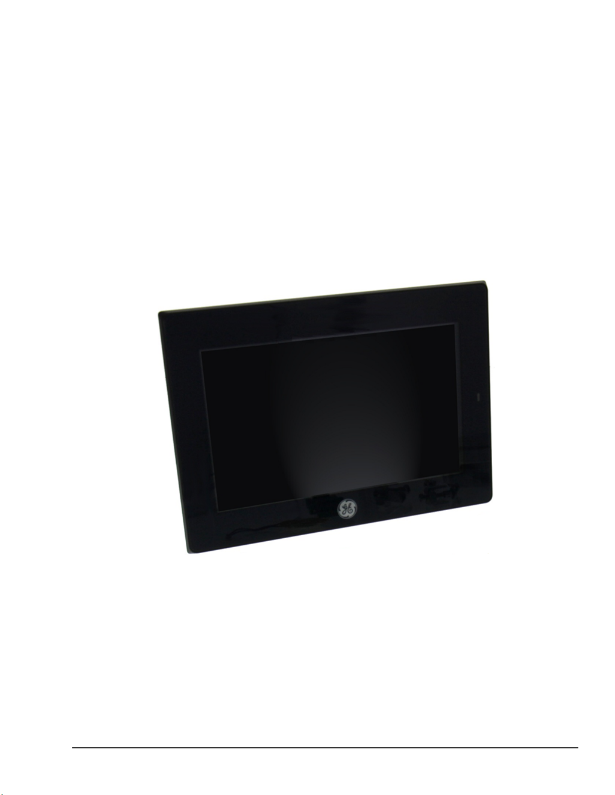
This manual specifically
describes the QuickPanel
IC755CxS06RDx,
IC755CxWxxCDx and
IC755CxSxxCDx display units.
+
The QuickPanel
maximum flexibility. The design is based on an Advanced RISC Machine (ARM) core
micro-processor to combine a high-resolution touchscreen operator interface with a
variety of communications options. Users can connect to most industrial equipment using
the QuickPanel
The QuickPanel
applications. A section of Dynamic Random Access Memory (DRAM) is split between
the operating system, an object store, and application memory. Additionally, a section of
Non-volatile Random Access Flash Memory (NOVRAM), functioning as a virtual hard
drive, is divided between the operating system and persistent storage for application
programs. Retentive memory is a battery-backed Static Random Access Memory
(SRAM) to store and protect data during a power failure.
+
Operator Interface is an all-in-one micro-computer designed for
+
communications ports.
+
is equipped with several memory types to satisfy the most demanding
QuickPanel+Operator Interface Display
Overview GFK-2847R 9
For public disclosure
Page 10
1.1 Specifications
1.1.1 Physical Specifications and Mounting Options
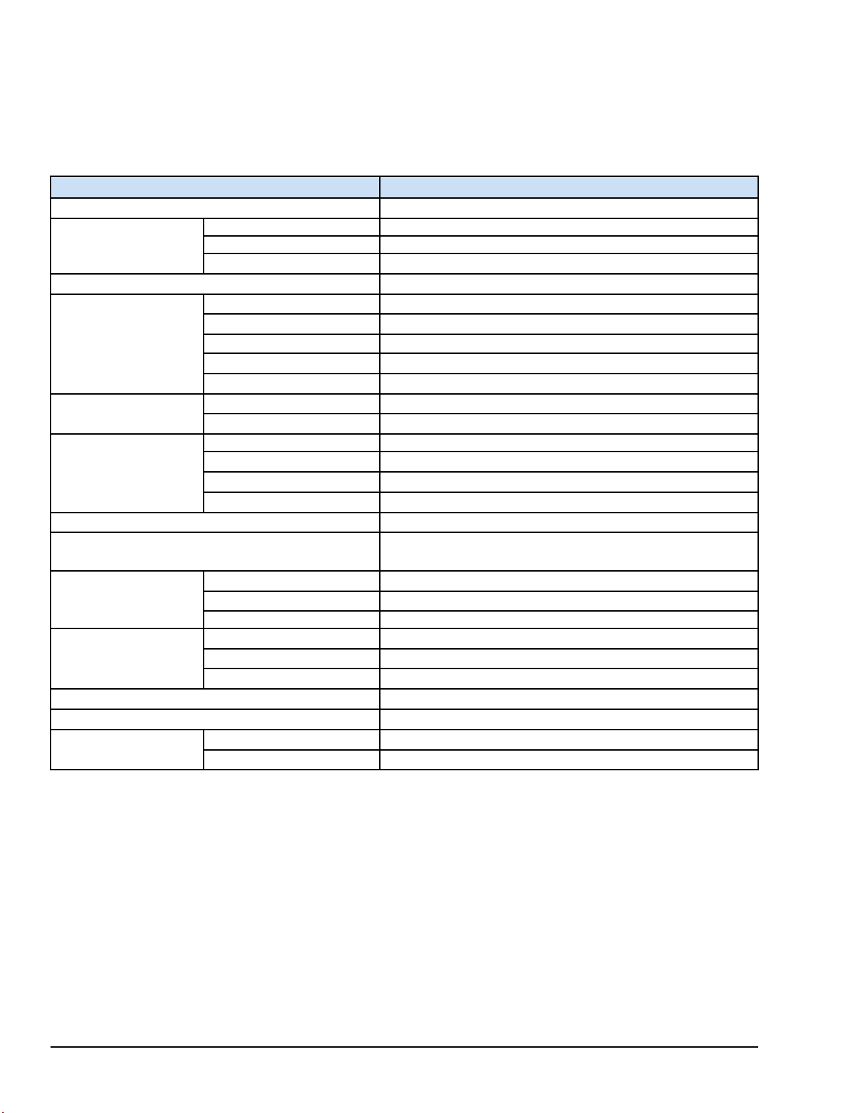
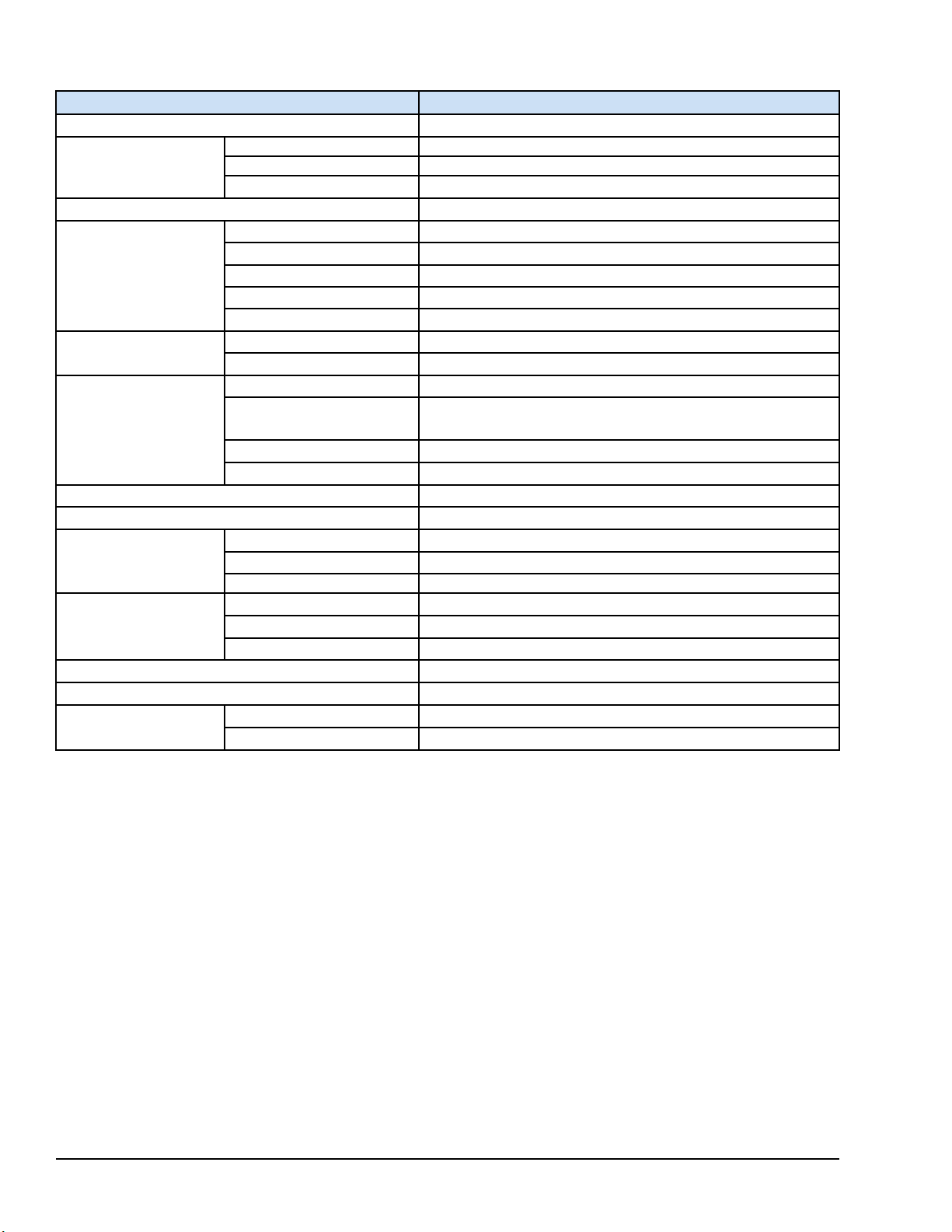
1.1.1.1 IC755CxS06RDx Specifications
Item
Processor
RAM DDR3 SDRAM 512 MB
Memory
Operating System Microsoft Windows Embedded Compact 7
Display
Touchscreen
Communications
Storage
Audio
Noise Immunity
Input power
Dimensions (L×W×D) 192 × 137 × 36 mm (7.56 × 5.39 × 1.42 in)
Weight 0.7 Kg (1.54 lb)
Mounting Options
ROM NAND FLASH 256 MB
SRAM
Type
Resolution
Color
Brightness
Backlight
Touch Panel Type Analog Resistive
Multi-touch
Ethernet Port 1x10Base-T / 100Base-TX
Serial Port
USB, Host
USB, Device
Noise Voltage 1500 V p-p
Pulse Duration
Rise Time 1ns
Rated Voltage 24 V dc ±20% (3-pin connector)
Power Consumption
Frame Ground (FG) Frame Ground (GND) is connected internally to Signal GND
Panel Cutout Dimensions
VESA Mount
Freescale i.MX535 (1 GHz ARM Cortex A8)
512 KB (with battery backup)
5.7” TFT LCD
320(W) x 240(H) pixels QVGA
65,536
375 cd/m
LED
Single-touch
1x RS-232C (COM1) (5-pin connector)
2x USB 2.0 (Type-A) maximum power (5 V at 0.5 A)
1x USB 2.0 (mini Type-B)
1x SD/SDHC card slot
1x Mic In (Mono) (3.5 mm jack),
1x Line Out (Stereo) (3.5 mm jack)
1µs
15 W maximum
183.50 × 128.50 mm (7.22 × 5.06 in)
75 x 75 mm (2.95 x 2.95 in)
2
Specification
10 GFK-2847R QuickPanel⁺ Operator Interface User Manual
For public disclosure
Page 11
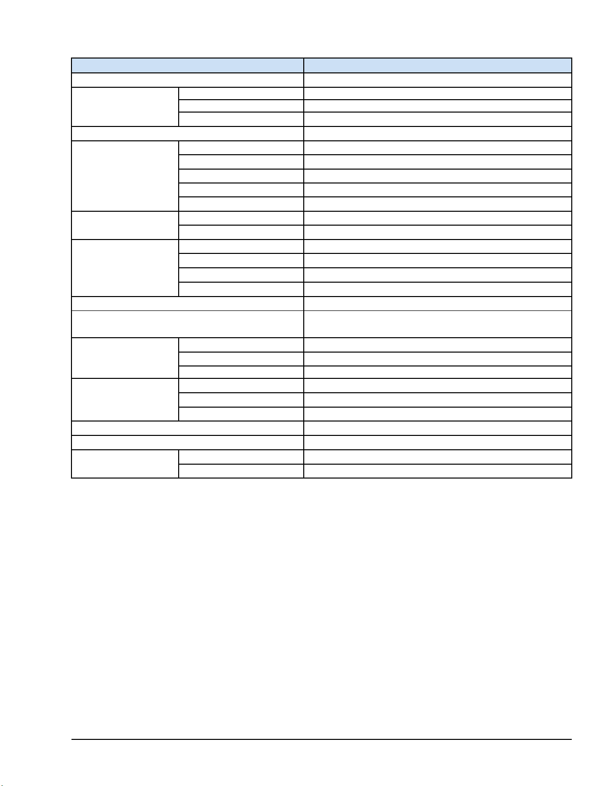
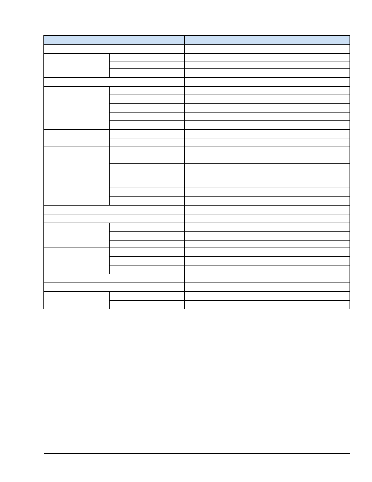
1.1.1.2 IC755CxW07CDx Specifications
Item
Processor Freescale i.MX535 (1 GHz ARM Cortex A8)
RAM DDR2 SDRAM 512 MB
Memory
Operating System Microsoft Windows Embedded Compact 7
Display
Touchscreen
Communications
Storage 1x SD/SDHC card slot
Audio
Noise Immunity
Input power
Dimensions (L×W×D) 192 × 137 × 36 mm (7.56 × 5.39 × 1.42 in)
Weight 0.80 kg (1.76 lbs)
Mounting Options
ROM SLC NAND 256 MB
SRAM 512 KB (with battery backup)
Type 7" Widescreen TFT LCD
Resolution 800(W) x 480(H) pixels WVGA
Color 65,536
Brightness 310 cd/m
Backlight LED
Touch Panel Type Projected capacitive
Multi-touch Two-point
Ethernet Port 1x 10/100Base-T (RJ-45)
Serial Port 1x RS-232 UART port (5-pin connector)
USB, Host 2x USB 2.0 (Type-A) maximum power (5 V at 0.5 A)
USB, Device 1x USB 2.0 (mini Type-B)
1x Mic In (Mono) (3.5 mm jack)
1x Line Out (Stereo) (3.5 mm jack)
Noise voltage 1500 V p-p
Pulse duration 1µs
Rise time 1ns
Rated Voltage 24 V dc ±20% (3-pin connector)
Power Consumption
Frame Ground (FG) Frame GND is connected internally to Signal GND
Panel Cutout Dimensions
VESA Mount
15 W maximum, 0.625 A
183.50 × 128.50 mm (7.22 × 5.06 in)
75 x 75 mm (2.95 x 2.95 in)
2
Specification
Overview GFK-2847R 11
For public disclosure
Page 12
1.1.1.3 IC755CxS10CDx Specifications
Item
Processor Freescale i.MX535 (1 GHz ARM Cortex A8)
RAM DDR3 SDRAM 1 GB
Memory
Operating System Microsoft Windows Embedded Compact 7
Display
Touchscreen
Communications
Storage 1x SD/SDHC card slot
Audio
Noise Immunity
Input power
Dimensions (L×W×D) 278 × 222 × 65 mm (10.95 × 8.74 × 2.56 in)
Weight 2.40 kg (5.29 lbs)
Mounting Options
ROM SLC NAND 512 MB
SRAM 512 KB (with battery backup)
Type 10.5" Standard TFT LCD
Resolution 800(W) x 600(H) pixels SVGA
Color 65,536
Brightness 400 cd/m
Backlight LED
Touch Panel Type Projected capacitive
Multi-touch Two-point
Ethernet Port
Serial Port
USB, Host 2x USB 2.0 (Type-A) maximum power (5 V at 0.5 A)
USB, Device 1x USB 2.0 (mini Type-B)
Noise voltage 1500 V p-p
Pulse duration 1µs
Rise time 1ns
Rated Voltage 12/24 V dc ±20% (3-pin connector)
Power Consumption
Frame Ground (FG) Frame GND is connected internally to Signal GND
Panel Cutout Dimensions
VESA Mount
2x 10/100Base-T (RJ-45)
1x RS-232 UART port
1x RS-232/485 port (2x 5-pin connector)
1x Line Out (Stereo) (3.5 mm jack)
18 W maximum 1.5 / 0.75 A
266 × 210 mm (10.47 × 8.27 in)
100 x 100 mm (3.94 x 3.94 in)
2
Specification
12 GFK-2847R QuickPanel⁺ Operator Interface User Manual
For public disclosure
Page 13
1.1.1.4 IC755CxS12CDx Specifications
Item
Processor Freescale i.MX535 (1 GHz ARM Cortex A8)
RAM DDR3 SDRAM 1 GB
Memory
Operating System Microsoft Windows Embedded Compact 7
Display
Touchscreen
Communications
Storage 1x SD/SDHC card slot
Audio
Noise Immunity
Input power
Dimensions (L×W×D) 314 × 248 × 65 mm (12.36 × 9.76 × 2.56 in)
Weight 3 kg (6.61 lbs)
Mounting Options
ROM SLC NAND 512 MB
SRAM 512 KB (with battery backup)
Type 12.1" Standard TFT LCD
Resolution 800(W) x 600(H) pixels SVGA
Color 65,536
Brightness 450 cd/m
Backlight LED
Touch Panel Type Projected capacitive
Multi-touch Two-point
Ethernet Port
Serial Port
USB, Host 2x USB 2.0 (Type-A) max power (5 V at 0.5 A)
USB, Device 1x USB 2.0 (mini Type-B)
Noise voltage 1500 V p-p
Pulse duration 1µs
Rise time 1ns
Rated Voltage 12/24 V dc ±20% (3-pin connector)
Power Consumption
Frame Ground (FG) Frame GND is connected internally to Signal GND
Panel Cutout Dimensions 302 × 228 mm (11.89 × 8.98 in)
VESA Mount 100 x 100 mm (3.94 x 3.94 in)
2x 10/100Base-T (RJ-45)
1x 10/100Base-T (RJ-45) for IC755CxS12CDA
1x RS-232 UART port
1x RS-232/485 port (2x 5-pin connector)
(1x 10-pin connector for IC755CxS12CDA)
1x Line Out (Stereo) (3.5 mm jack)
30 W maximum, 2.5 / 1.25 A
2
Specification
Overview GFK-2847R 13
For public disclosure
Page 14

1.1.1.5 IC755CxS15CDx Specifications
Item
Processor Freescale i.MX535 (1 GHz ARM Cortex A8)
RAM DDR3 SDRAM 1 GB
Memory
Operating System Microsoft Windows Embedded Compact 7
Display
Touchscreen
Communications
Storage 1x SD/SDHC card slot
Audio
Noise Immunity
Input power
Dimensions (L×W×D) 399 × 323 × 70 mm (15.71 × 12.72 × 2.76 in)
Weight 4.46 kg (9.83 lbs)
Mounting Options
ROM SLC NAND 512 MB
SRAM 512 KB (with battery backup)
Type 15" Standard TFT LCD
Resolution 1024(W) x 768(H) pixels XGA
Color 65,536
Brightness 310 cd/m
Backlight LED
Touch Panel Type Projected capacitive
Multi-touch Two-point
Ethernet Port
Serial Port
USB, Host 2x USB 2.0 (Type-A) maximum power (5 V at 0.5 A)
USB, Device 1x USB 2.0 (mini Type-B)
Noise voltage 1500 V p-p
Pulse duration 1µs
Rise time 1ns
Rated Voltage 12/24 V dc ±20% (3-pin connector)
Power Consumption
Frame Ground (FG) Frame GND is connected internally to Signal GND
Panel Cutout Dimensions 379 × 305 mm (14.92 × 12.01 in)
VESA Mount 100 x 100 mm (3.94 x 3.94 in)
2x 10/100Base-T (RJ-45)
1x RS-232 UART port
1x RS-232/485 port (2x 5-pin connector)
1x Line Out (Stereo) (3.5 mm jack)
30 W maximum, 2.5 / 1.25 A
2
Specification
14 GFK-2847R QuickPanel⁺ Operator Interface User Manual
For public disclosure
Page 15

1.1.2 Environmental Specifications
Note Install the QuickPanel+in a well-ventilated location that is not exposed to dust,
corrosive gases or liquids, rain, strong ultra-violet light or direct sunlight, and meets the
following specifications.
Item IC755CxS06RDx IC755CxW07CDx IC755CxS10CDx IC755CxS12CDx IC755CxS15CDx
Cooling
Ambient
Operating
Temperature
Ambient
Storage
Temperature
Ambient
Humidity
(Operating
and Storage)
Environment
Vibration
Resistance
Altitude
RoHS
Enclosure
Rating
85% RH Non-condensing, wet-bulb temperature: 30°C (86 °F) or less
Pollution Degree 2, Indoor use only
5 to 9 Hz single-amplitude 3.5 mm; 9 to 150 Hz constant-accelerated velocity 9.8 m/s
X, Y, Z directions 10 time (100 minutes) (Compliance 3502, IEC61131-2 JIS B)
800~1114 hPa, altitude up to 2000 m (6561.68 ft)
Compliant with EU RoHS Directive 2011/65/EU
UL Type 4X rating; IP65 in panel mount only
Natural convection
0 to 55°C (32 to 131 °F)
-10 to 60°C (14 to 140 °F)
2
;
Note For additional product standards and agency approvals, refer to Appendix A.
Overview GFK-2847R 15
For public disclosure
Page 16

Notes
16 GFK-2847R QuickPanel⁺ Operator Interface User Manual
For public disclosure
Page 17

2 Hardware
This chapter describes the QuickPanel+hardware features, including physical
characteristics and LED indicators.
2.1 Physical Characteristics
In addition to the primary touchscreen interface, the QuickPanel+Operator Interface
supports a variety of communication ports. The following diagrams illustrate the physical
layout of the QuickPanel
communications ports, and connectors.
+
Operator Interface, including locations of status LEDs,
Hardware GFK-2847R 17
For public disclosure
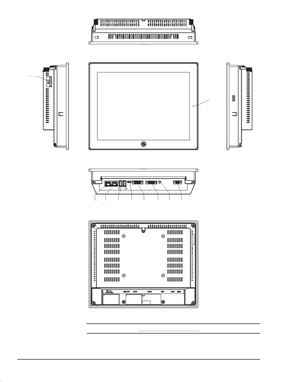
Page 18
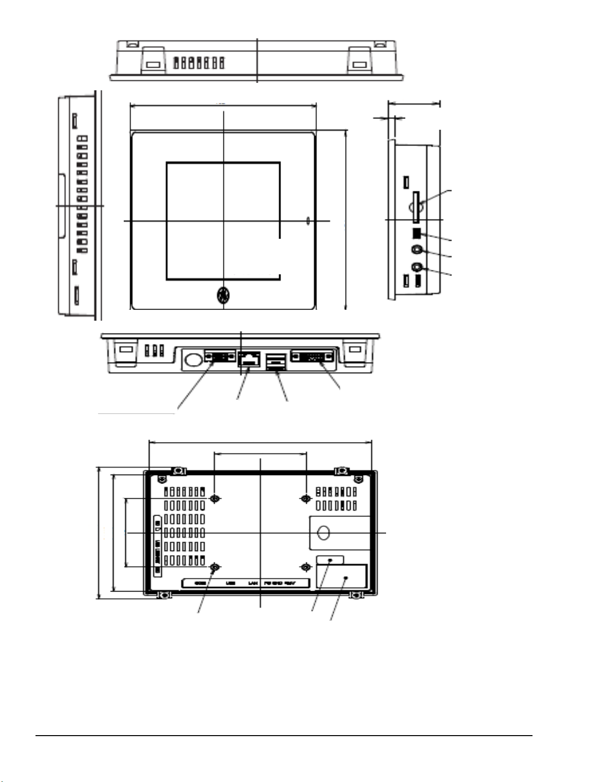
SD Card
USB Device
LINE OUT
MIC IN
Input Power
LAN
USB Host Ports
Serial Interface
LCD Active Area
115.2 x 86.4
(4.5 x 3.4 in)
115.2
(4.5 in)
192 (7.56 in) x 2
36 (1.42 in) x 2
137 (5.39 in) x 2
183.50 (7.22 in)
75 (2.95 in)
75 (2.95 in)
128.50 (5.06 in)
144.7 (5.70 in)
Effective Screw Depth 6 mm (0.24 in)
Product Nameplate
Battery Cover
License Label
IC755CxS06RDx Hardware Features
18 GFK-2847R QuickPanel⁺ Operator Interface User Manual
For public disclosure
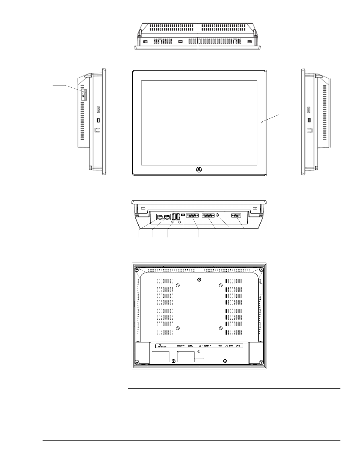
Page 19
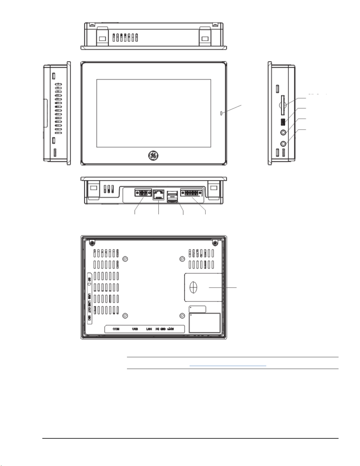
Battery
Cover
COM
USB Host
Ports
LAN
Input
Power
SD Card
MICRO USB
LINE OUT
MIC IN
Status
Indicator LED
Touchscreen
LCD
IC755CxW07CDx Hardware Features
Note Refer to the section IC755CxW07CDx Specifications for drawing dimensions.
Hardware GFK-2847R 19
For public disclosure
Page 20
Status
Indicator LED
Touchscreen
LCD
SD Card
USB
Host
Ports
MICRO
USB
LAN2
COM1LAN1
Input
Power
LINE
OUT
COM2
IC755CxS10CDx Hardware Features
Note Refer to the section IC755CxS10CDx Specifications for drawing dimensions.
20 GFK-2847R QuickPanel⁺ Operator Interface User Manual
For public disclosure
Page 21
!
!
IC755CxS12CDx Hardware Features
Note Refer to the section IC755CxS12CDx Specifications for drawing dimensions.
Hardware GFK-2847R 21
For public disclosure
Page 22
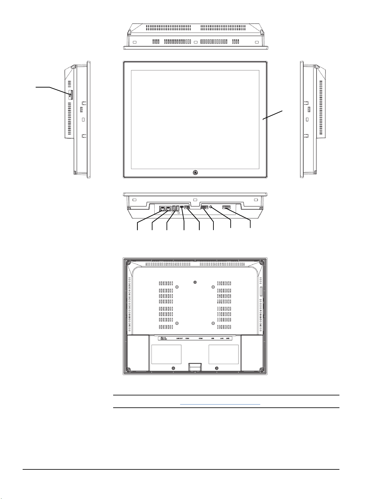
Touchscreen
LCD
Status
Indicator
LED
SD Card
Input
Power
LINE
OUT
USB
Host
Ports
MICRO
USB
COM2
LAN2
COM1
LAN1
IC755CxS15CDx Hardware Features
Note Refer to the section IC755CxS15CDx Specifications for drawing dimensions.
22 GFK-2847R QuickPanel⁺ Operator Interface User Manual
For public disclosure
Page 23
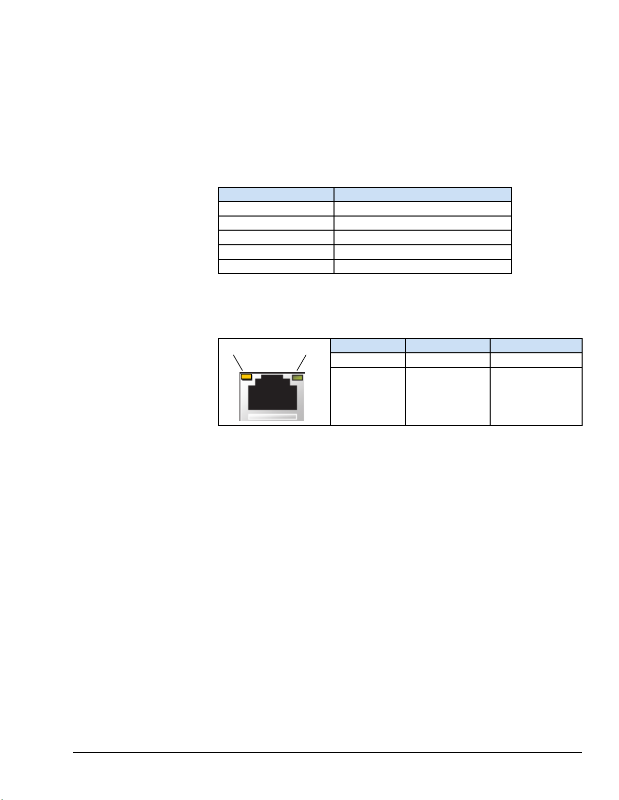
2.2 LED Indicators
Speed Link Activity
The QuickPanel+Operator Interface provides LED indication for the following:
• Operation status
• Ethernet Port operation
2.2.1 Operation Status LEDs
The QuickPanel+has one tri-color LED that provides visual operation status indication
for IC755CxS06RDx, IC755CxW07CDx, the and IC755CxSxxCDx units.
LED State
Amber, solid
Green, solid
Green, blinking Backlight off
Red, blinking Backlight failure
Off
QuickPanel
Operating system starting
Normal operating state
Power not applied to unit
+
State
2.2.2 Ethernet Port Operation LEDs
The Ethernet port has two LED indicators: Speed and Link Activity.
LED LED State
Speed
Link Activity
Yellow, on
Green, on
Operating State
10/100
Link status
Hardware GFK-2847R 23
For public disclosure
Page 24

Notes
24 GFK-2847R QuickPanel⁺ Operator Interface User Manual
For public disclosure
Page 25

3 Software
This chapter provides QuickPanel+software information and procedures to perform the
most common tasks.
3.1 Operating System
Refer to http://windows.
microsoft.com.
The QuickPanel+operating system (OS), Microsoft Windows Embedded Compact 7, is a
full 32-bit OS with graphical user interface (GUI). It is stored in flash memory and copied
to a block of DRAM for execution. The OS automatically starts following QuickPanel
unit powerup or reset.
3.2 Backup Utility
The QuickPanel
changes made to the Windows Registry or Desktop to Flash Memory. The Backup Utility
achieves the following:
• Stores the Windows Embedded Compact 7 registry (including any control panel
• Stores changes (or additions) made to the \Windows sub-tree of the file system in the
Attention
+
is not battery powered; therefore, a Backup Utility feature saves the
settings) in Flash memory
user block of flash memory
+
Run the Backup Utility after configuration changes
to the operating system or installing applications,
and before shutdown.
3.3 Storage Manager
Storage Manager is accessed
from the Control Panel folder.
Online help is available.
Software GFK-2847R 25
For public disclosure
Use Microsoft Storage Manager to repair or format lost or corrupted data volumes
existing in the SD Card, battery-backed SRAM (BBSRAM), or USB Flash Keys (thumb
drives).
Note Data volumes existing in the main flash file system of the QuickPanel+may not be
repaired by Storage Manager.
Page 26
3.4 Copy Project to SD Card
The custom utility Copy Project to SD Card transfers Proficy Machine Edition View and
Control projects between compatible QuickPanel
Caution
➢➢ To copy a Proficy Machine Edition project to an SD card
1. Verify that there is a blank SD card in the SD card port.
2. Double tap the Copy Project to SD Card icon on the desktop.
3. From the Copy Project Query confirmation window, tap Yes.
Caution
+
units using SD cards.
Before disconnecting power, verify that the copy or
update operation is complete (no busy message or
wait cursor).
Copying a project while Proficy Machine Edition
runtimes are active may cause an incomplete copy to
be created if the runtimes are also writing to files in
the project folders. If the utility detects this
situation, it will notify you to stop the runtimes
before making the backup. You will not be able to
create a backup while the runtimes are writing files.
3.5 Proficy Machine Edition Project Update
Update a Proficy Machine Edition (PME) application that is currently stored on the
+
QuickPanel
➢➢ To update a Machine Edition project
1. Insert the flash device containing an upgraded version of the Proficy Machine Edition
project into the appropriate port.
2. Restart the unit.
Note Depending on set options, the update may or may not be enabled, or may
update automatically. If there is more than one flash device with a valid project copy
present, a Select Media confirmation window displays, prompting you to choose with
which flash device to update Select the device from the list and click OK to continue.
When a valid project is found on the flash device, you will be prompted to install the
project or skip it. Tap OK to install or Cancel to skip the installation, and continue
to restart. If an invalid project is found, an error message displays. This window must
be closed before the unit will restart.
3. Remove the flash device from the port.
unit with a revision stored on a flash device, such as an SD card.
26 GFK-2847R QuickPanel⁺ Operator Interface User Manual
For public disclosure
Page 27

3.6 FTP Server
The File Transfer Protocol (FTP) server included with the QuickPanel+unit supports
standard (RFC 959). It does not support Secure File Transfer Protocol (SFTP) or implicit
FTPS, which uses different ports and is based on Secure Shell (SSH) rather than Secure
Sockets Layer (SSL).
The FTP server is configured with the Quick Panel
not enabled. Once enabled, a background program will run, waiting for clients to connect.
Up to ten connections are supported. Sessions that are idle for five minutes are terminated
by the server.
The server supports non-secure operation. All information including username, password,
and data is transmitted with no encryption and is susceptible to packet sniffing and
various FTP attacks.
Note If the server status is changed, the QuickPanel+must be restarted before changes
take effect.
+
Setup Tool. By default, the server is
3.6.1 Remote User Authentication
The FTP root directory is
available from the
QuickPanel
root of the flash device.
+
as \, and is the
The server only supports anonymous login with password requested (but not validated).
This may prevent some types of attacks and is required by some clients. Once connected,
the remote user is logged into the FTP root directory.
3.6.2 FTP with Removable Flash Devices
All removable flash devices remote-FTP users as directories off the FTP root directory.
Computer Flash card partitions display as directories such as \SDMemory and USB Flash
Keys display as directories such as \Hard Disk. Full access privileges are granted for the
client in these folders/devices.
Removable flash device directories are captured when a session is opened and are not
changed while the session exists. If you start without an installed SD Card, close your
session and log on again to view the SD Card directory. If the SD Card existed when you
logged on, and is removed and inserted, it will still work, provided the SD Card’s device
name did not change during reinsertion.
Software GFK-2847R 27
For public disclosure
Page 28

3.7 HTTP Server
3.8 SNTP Server
The HyperText Transfer Protocol (HTTP) server included with the QuickPanel+supports
standard (RFC 2616). The HTTP server is configured with the Quick Panel+ Setup Tool.
By default, the server is not enabled. Once enabled, a background program will run,
waiting for clients to connect. From the QuickPanel
page is located in \Windows\www\wwwpub.
The server supports non-secure port 80 operation.
Note If the server status is changed, the QuickPanel+must be restarted before changes
take effect.
The SNTP server included with the QuickPanel+supports SNTP Version 4 for IPv4, IPv6
and OSI. The SNTP server is configured with the Quick Panel+ Setup Tool. By default,
the server is not enabled. Once enabled, the server will refresh the time specified in the
setup tool configuration. Pressing the Update Now button immediately obtains the time
from the configured time server.
The SNTP server supports non-secure UDP port 123 operation.
+
Operator Interface, the default web
28 GFK-2847R QuickPanel⁺ Operator Interface User Manual
For public disclosure
Page 29

3.9 QuickPanel+OS Utilities Settings Tool
DIP switches are set in the
OFF position (default) in the
factory.
The DIP Switch feature is
designed as a security
measurement. However,
security requirements can also
be met using the gesture-based
feature.
Prior to the listed firmware
builds, these operations were
only supported using the DIP
Switch settings.
The QuickPanel+Operator Interface is equipped with DIP switches to perform control
functionality, as follows:
• DIP Switch 1 (SW2 Switch) enables firmware upgrade. Firmware upgrade is
allowed only after turning this switch in the ON position. It is highly recommended
to turn the switch position to OFF after firmware upgrade is completed as a security
measurement.
• DIP Switch 2 (SW2 Switch) controls Force Startup. Turning this switch to the ON
position forces the startup applications to run when the operating system is started.
Some operators find it difficult to use the DIP Switch settings to perform these functions
(such as removing the back plate of the device and adjusting the positions of DIP Switch
for each operation). As an alternative to using the DIP Switch settings, the QuickPanel
+
OS Utilities Settings tool contains finger gesture-based utilities to perform the same
operations. This functionality is available with the firmware builds listed in the following
table.
QuickPanel+OS Utilities Settings Tool Support
QuickPanel+Product
IC755CxS06RDx (6" Display) 01 (initial release)
IC755CxW07CDx (7” Display)
IC755CxS10CDx (10” Display)
IC755CxS12CDx (12” Display)
IC755CxS15CDx (15” Display)
Firmware Build
21
12
The tool operation buttons for each utility only respond to a double-tap finger gesture. It
will not accept any keyboard or mouse clicks, finger simulator-based inputs, or click
inputs from any remote touch-based device. The user can access the tool from the Start
menu by selecting Programs, System, and QuickPanel
+
OS Utilities Settings on
the device. The tool can be used to perform the following operations using the double-tap
feature, without adjusting the DIP Switch positions:
• Firmware Upgrade
• Bypass Startup Programs
• Reset Enhanced Security
• Enable/Disable SNMP Agent
For security, only permit these operations when the
operator is physically located near the QuickPanel
+
and require that users perform a physical action on
Attention
the device.
Software GFK-2847R 29
For public disclosure
Page 30

3.9.1 Firmware Upgrade
This utility operates similar to
the QuickPanel
+
Update Tool,
which comes with the OS
image upgrade binaries. The
operator can continue to use
the QuickPanel
+
Update Tool
to use the DIP Switch feature.
The Firmware Upgrade utility setting enables operators to upgrade the firmware.
Firmware updates are not supported over Ethernet or Serial interfaces. Insert the media
(SD Card) containing the required files for firmware upgrade and perform the following
procedure.
Note Make sure the copy of required binaries to the SD card is not within a folder.
Note The firmware package contains encrypted .nbo files. Use the PreUpdate.exe tool to
decrypt the .nbo files before using them for upgrade.
After a firmware upgrade, which refreshes the device fresh, the user must download the
project again and install their own tools (including third party tools) on the device.
Note It is recommended that the user back up any important data prior to firmware
upgrade so that they can replace the data after firmware upgrade if necessary.
If the current firmware build version on the
QuickPanel
+
is any of the following, refer to the
section Firmware Upgrade for Specific Build Version:
• Build 3 or below for IC755CxS06RDx
(6” Display)
• Build 23 or below for IC755CxW07CDx
(7” Display)
Attention
• Build 14 or below for IC755CxS10CDx
(10" Display), IC755CxS12CDx
(12” Display), and IC755CxS15CDx
(15” Display)
➢➢ To perform a firmware upgrade
1. From the Start menu, select Programs, System, and QuickPanel
Settings Tool to display the QuickPanel
2. Upgrade the firmware.
+
OS Utilities Settings window.
+
OS Utilities
30 GFK-2847R QuickPanel⁺ Operator Interface User Manual
For public disclosure
Page 31

From the QuickPanel+OS Utilities
Settings window, select Firmware
Upgrade, then double-tap Upgrade.
3. The operator interface guides the operator through the firmware upgrade process.
After successful upgrade, restart the device.
4. Download the project and install any site-specific tools, including third party tools,
on the device.
Software GFK-2847R 31
For public disclosure
Page 32

3.9.2 Firmware Upgrade for Specific Build Version
From the QuickPanel+ Update Tool dialog box, click Upgrade.
The following procedure is applicable to the following QuickPanel+display units:
• QuickPanel
• QuickPanel
• QuickPanel
+
IC755CxS06RDx (6” Display) with build 3 or below
+
IC755CxW07CDx (7” Display) with build 23 or below
+
IC755CxS10CDx (10" Display), IC755CxS12CDx (12” Display), and
IC755CxS15CDx (15” Display) with build 14 or below
➢➢ To perform a firmware upgrade for a specific firmware build version
1. Put the files in the firmware package on the SD Card.
2. Double-click QPPlusUpdate.exe and run the program.
3. Perform the firmware upgrade.
For a QuickPanel+7” inch Display unit, the
following message displays during the process of
firmware upgrade. You must re-run the
QPPlusUpdate.exe program after reboot, which
means you will run the QPPlusUpdate.exe program
Attention
QuickPanel+7” inch Display Reboot and Run Program Message
a total of two times to complete the upgrade process.
32 GFK-2847R QuickPanel⁺ Operator Interface User Manual
For public disclosure
Page 33

3.9.3 Bypass Startup Programs
From the QuickPanel+OS Utilities Settings
window, select Bypass Startup Programs.
To use the DIP Switch feature to perform this
operation, select Use DIP Switch.
To use the double-tap feature to perform
this operation, double-tap Enable.
This utility functions the same
as disabling or enabling the
Don’t startup Program
functionality using DIP Switch
Position 2.
The Bypass Startup Programs utility enables the operator to choose the gesture-based
feature or DIP Switch (Use DIP Switch) feature to perform the Force Startup operation.
➢➢ To bypass startup programs and force startup
1. From the Start menu, select Programs, System, and QuickPanel
Settings Tool to display the QuickPanel
+
OS Utilities Settings window.
+
OS Utilities
2. Enable or disable the bypass startup programs feature.
Software GFK-2847R 33
For public disclosure
Page 34

If Enable is double-tapped, the
startup window displays and all
startup programs are enabled to run .
If Disable is double-tapped, the startup
window displays. Click Don’t run
Startup programs to stop all startup
programs from running .
If Use DIP Switch is selected, Don’t run StartUp Programs displays on the startup
window based on the position of DIP Switch 2.
34 GFK-2847R QuickPanel⁺ Operator Interface User Manual
For public disclosure
Page 35

3.9.4 Reset Enhanced Security
From the QuickPanel+OS
Utilities Settings window, select
Reset Enhanced Security, then
double-tap Disable.
The QuickPanel+Operator Interface is configured using the Proficy Machine Edition
(PME) application. Using the PME Enhanced Security feature, users can specify
password protection for any network-connected QuickPanel
operations, such as the download operation. Every operation to connect to the device
requires a password.
If you forget or do not know your password, the Reset Enhanced Security feature enables
a QuickPanel
+
configuration download on the device by permitting the user to disable the
Enhanced Security feature using the double-tap feature.
Note Prior to support of the QuickPanel+OS Utilities Settings Tool, if the user forgot or
did not know their password, the only resolution was to contact Technical Support to reset
the password or upgrade the firmware on the device.
➢➢ To disable Enhanced Security
1. From the Start menu, select Programs, System, and QuickPanel
Settings Tool to display the QuickPanel
+
OS Utilities Settings window.
2. Disable the Enhanced Security setting.
+
device to perform certain
+
OS Utilities
Software GFK-2847R 35
For public disclosure
Page 36
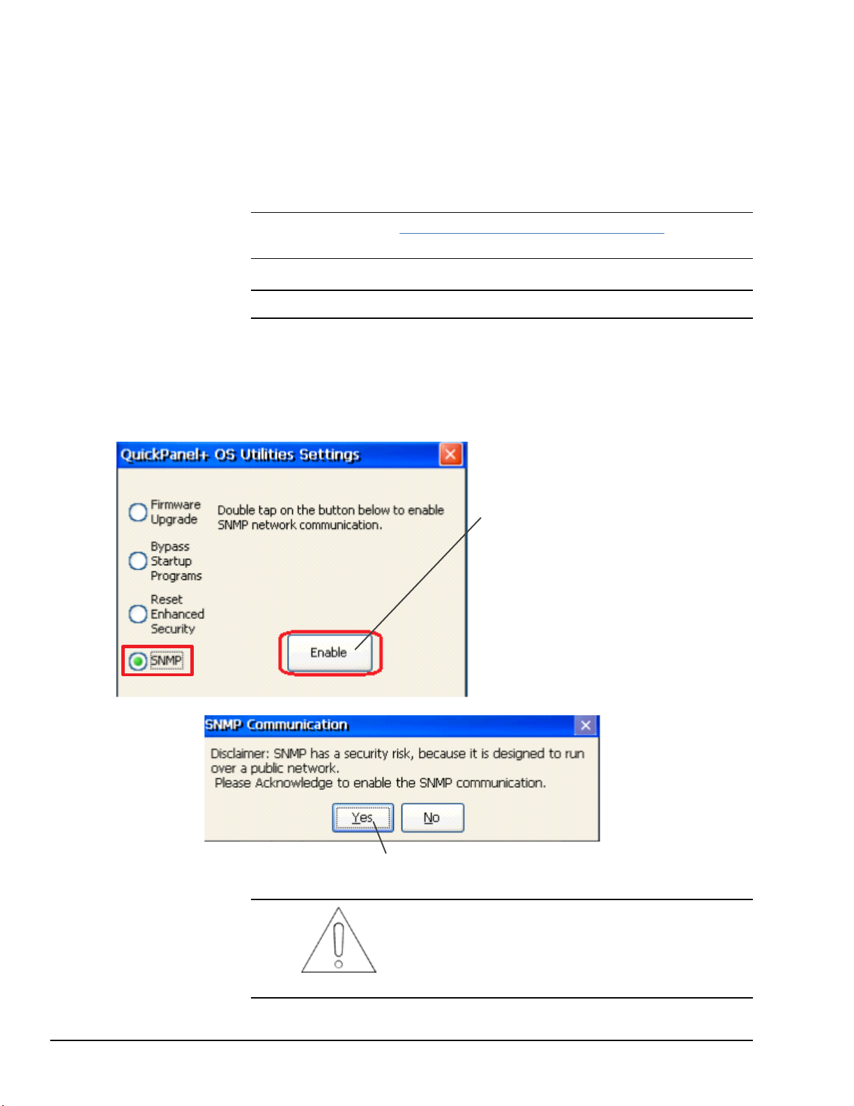
3.9.5 Enable or Disable SNMP Agent
From the QuickPanel+OS Utilities
Settings window, select SNMP.
Double-tap Enable to enable
SNMP communication.
Click Yes to acknowledge the security
risk and enable SNMP communication.
The QuickPanel+Operator Interface can be enabled as a Simple Network Management
Protocol (SNMP) Agent with the capability to communicate with SNMP Managers for
notification of Traps and responding to Query HMI Tag values.
Since it is designed to run over a public network, SNMP communication is disabled by
default on the QuickPanel
feature requires a tactile input gesture to enable and disable SNMP communication.
Note Refer to the section Simple Network Management Protocol (SNMP) for further
details.
Note Enabling or disabling SNMP communication is a one-time user configuration.
➢➢ To enable the SNMP Agent
1. From the Start menu, select Programs, System, and QuickPanel
Settings Tool to display the QuickPanel
2. Enable SNMP communication.
+
device for security reasons. As a security measure, the SNMP
+
OS Utilities
+
OS Utilities Settings window.
SNMP communication is enabled on the device only
when the user acknowledges this security dialog box
and clicks Yes.
Attention
36 GFK-2847R QuickPanel⁺ Operator Interface User Manual
For public disclosure
Page 37
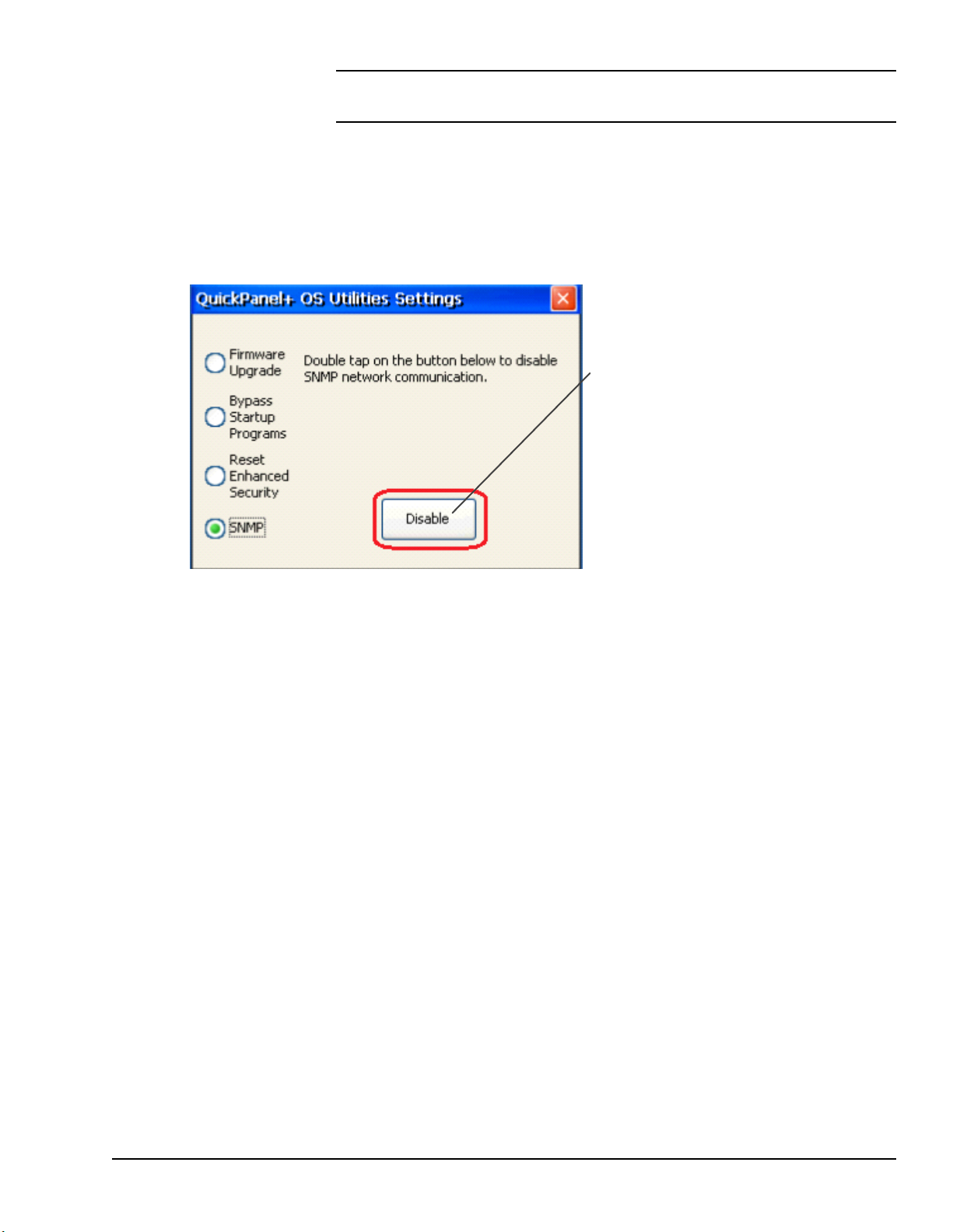
Note Any failure or errors while enabling or disabling the SNMP service would be
From the QuickPanel+OS Utilities
Settings window, select SNMP.
Double-tap Disable to disable
SNMP communication.
communicated to the user through a dialog box.
➢➢ To disable the SNMP Agent
1. From the Start menu, select Programs, System, and QuickPanel
Settings Tool to display the QuickPanel
+
OS Utilities Settings window.
+
OS Utilities
2. Disable SNMP communication.
Software GFK-2847R 37
For public disclosure
Page 38
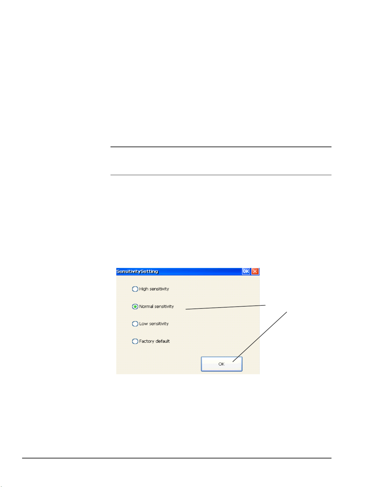
3.10 Display Screen Sensitivity Tool
Select the sensitivity
level and press OK.
The QuickPanel+7”, 10”, 12”, and 15” display units use capacitive screen technology that
is far more responsive than the previously used resistive touchscreen technology.
Resistive screens required the operator to firmly press down on the resistive overlay for a
response. Capacitive screens rely on the capacitive properties of the operators finger
pressing lightly on the screen.
If the operator is wearing gloves, this can affect the operation of the capacitive screens.
The thickness of the glove keeps the operator’s finger slightly further from the screen. To
accommodate gloved operation, the Sensitivity Tool allows the screen sensitivity to be set
to a higher level. Setting the screen sensitivity to High enables the QuickPanel
screen to operate with the user wearing most types of work gloves. For thicker gloves, the
user may need to press down more firmly to place the finger closer to the screen, which
causes the finger pad to spread out slightly to make a larger capacitive area.
Note Gloved operation works best when the operator is wearing gloves that fit. If the
fingers do not extend to the end of the glove, the empty space at the fingertip may make it
difficult to operate the display screen while wearing gloves.
Setting the screen sensitivity to Low enables the QuickPanel+operator actions to be slow
and deliberate as they were using resistive screens. With low sensitivity, the operator must
press firmly down on the display screen for a response.
+
display
➢➢ To modify the Sensitivity Tool
1. From the Start menu, select Programs, System, and Sensitivity Tool to display
the Sensitivity Setting window.
2. Set the sensitivity level.
38 GFK-2847R QuickPanel⁺ Operator Interface User Manual
For public disclosure
Page 39

3.11 Launch Application
From the Start menu,
select Programs, System,
and Launch Application.
From the Launch Application
window, tap an application icon
to start the application.
If the application is not listed,
select … to browse for and select
an application, then click to
open (start) the application.
The Launch application window contains the shortcuts to launch some of the major
QuickPanel
➢➢ To launch an application
+
Operator Interface applications.
Software GFK-2847R 39
For public disclosure
Page 40

3.12 VNC Server
From the Launch Application
window, tap the QP+VNC
Server application icon .
The VNC Server enables remote, visual connectivity to the QuickPanel+Operator
Interface from a laptop computer or a mobile device through the remote VNC Viewers.
User authentication of the VNC Server in the QuickPanel
+
is determined by the
configuration of the Enhanced Security feature on the device. If the Enhanced Security
feature is enabled for the device, a VNC Viewer can connect to the QuickPanel
+
on the
VNC Server. Connection is dependent upon user authentication with the correct
password. User password entry is validated with the Enhanced Security password. If the
Enhanced Security feature is disabled for the device, the VNC Server does not enforce
authentication of VNC Viewers.
The VNC Server is automatically launched during QuickPanel
+
startup. It can also be
launched manually from the Launch Application.
➢➢ To manually launch the VNC Server: from the Start menu, select Programs,
System, Launch Application and start the VNC Server application.
Note The VNC server starts approximately 40 sec after the QuickPanel+startup process
has completed.
40 GFK-2847R QuickPanel⁺ Operator Interface User Manual
For public disclosure
Page 41

3.13 Battery Life Prediction
Click OK and set the current date and time on the device.
The QuickPanel+Operator Interface provides an estimated lifespan of the battery in the
device. To display the battery life prediction, the current time on the QuickPanel
must be set. If a battery is not present, the QuickPanel
battery life prediction.
+
device
+
BatteryStatus tab cannot provide
➢➢ To display the battery life prediction: from the Start menu, select System,
open the QuickPanel
Battery Life Prediction Example
+
Setup tool, and select the BatteryStatus tab.
Note If the current time is not set on the device, the QuickPanel+Setup Tool dialog box
will not be capable of provide an accurate battery life prediction.
➢➢ To set the current time to display battery life prediction
1. If the current time is not set on the device, the QuickPanel
+
Setup Tool displays the
following message stating that the current date and time must be set on the device to
display the correct battery life prediction.
Software GFK-2847R 41
For public disclosure
Current Time Not Set Message
Page 42

2. After setting the current time, open the QuickPanel+Setup Tool, and select the
BatteryStatus tab to display the correct battery life prediction information.
Example of Battery Life Prediction Displayed After Current Time Set
3. If the battery was replaced or removed on the QuickPanel+, QuickPanel+Setup Tool
BatteryStatus displays two possible scenarios related to the battery.
(The battery life prediction is estimated based on this selection.)
Battery Status Options
42 GFK-2847R QuickPanel⁺ Operator Interface User Manual
For public disclosure
Page 43

4. If the option The battery is not present is selected, a message displays stating
Select the date from the calendar and click Next.
Select the current date and from the calendar and click Apply.
that battery life cannot be predicted without a battery installed on the device.
Battery is Not Present Message
5. If the option The battery was replaced is selected, enter the date of when the
battery was first used in a QuickPanel
first use in any QuickPanel
+
device, not just the current device.)
+
device. (This date should reflect the date of
6. Enter the current date.
Software GFK-2847R 43
For public disclosure
Page 44

7. Close and re-open the QuickPanel+Setup Tool dialog box to display the battery life
prediction information.
Close and Reopen Message
Battery Life Prediction Example after Battery Replacement
44 GFK-2847R QuickPanel⁺ Operator Interface User Manual
For public disclosure
Page 45

3.14 Simple Network Management Protocol (SNMP)
QuickPanel
+
Device
HMI Tags
Alarms
System Info
T
r
a
ps
/ A
l
a
r
m
s
(Por
t
1
62)
I
/O V
a
l
u
e
s
(
P
o
r
t
16
1)
U
D
P
SNMP
Manager
The SNMP is an application–layer protocol defined by the Internet Architecture Board
(IAB) in RFC1157 that is used for exchanging management information between network
devices. It is a part of the Transmission Control Protocol/Internet Protocol (TCP/IP) suite.
The QuickPanel
communicate with SNMP Managers (software tools run independently and are not part of
QuickPanel
• Send notification of HMI Alarms as Traps
• Provide live values for SNMP Manager’s GET/GETNEXT Query calls for HMI Tags
The following diagram illustrates the QuickPanel
communicate with a SNMP Manager for Traps notification and responding to Query HMI
Tag values.
+
Operator Interface is enabled as an SNMP Agent with the capability to
+
Operator Interface) for the following purposes:
+
operating as the SNMP Agent to
Software GFK-2847R 45
For public disclosure
QuickPanel+Management Information Base (MIB) Overview
The QuickPanel
parameters like HMI Tags, alarms, and such. The SNMP Manager uses the MIB to
request specific information for the SNMP Agent and translates the information as needed
for the SNMP Managers or Network Management System (NMS).
The MIB is a collection of information for managing network elements. It is a plain text
file, self-explanatory, and prepared based on the Structure of Management Information
(SMI), an adapted subset of Abstract Syntax Notation One (ASN.1) standard and
notation.
+
SNMP Agent maintains a MIB that describes the managed device
The QuickPanel+MIB is follows the SNMP V2c and
is also be compatible with SNMP V1 based on the
strictness of MIB compilers supported by SNMP
Managers.
Attention
The MIB is comprised of managed objects identified as Object Identifier (Object ID or
OID). Each Identifier is unique and denotes specific characteristics of a managed device.
When queried, the return value of each identifier may be different.
Page 46

The following figure displays the MIB tree structure and the private enterprise number
allocated by the Internet Assigned Numbers Authority (IANA) for the GE SNMP
products and OID for the QuickPanel
+
MIB:
OID for GEIP node: .1.3.6.1.4.1.24893
OID for qppMIB node: .1.3.6.1.4.1.24893.1.5.2.1.1
Attention
It is highly recommended that you pre-load GE
MIBs (GEIP-SMI.txt and GEIP-PRODUCTS-MIB.
txt in sequence) prior to loading the QuickPanelMIB.
mib file into SNMP Managers to avoid any MIB
compiler errors.
Contact technical support or download the MIBs
GEIP-SMI.txt and GEIP-PRODUCTS-MIB.txt
from the Support Site and QuickPanelMIB.mib can
be copied from the QuickPanel
+
device by
performing the procedure Export MIB to SD Card.
46 GFK-2847R QuickPanel⁺ Operator Interface User Manual
For public disclosure
Page 47

The following figure displays the HMI Alarms notification (TRAP information) with
alarm objects as part of the Alarm Record. The SNMP Manager is notified with the
TRAP information when alarms are generated on the HMI running on a QuickPanel
device.
OID for Alarm Trap: .1.3.6.1.4.1.24893.1.5.2.1.1.10
+
Software GFK-2847R 47
For public disclosure
Page 48

The following figure displays the list of HMI Tags that the SNMP Manager can query to
retrieve live values from the HMI running on a QuickPanel
+
device.
Note The list of all HMI tags are populated within the hmiTags node of MIB tree and the
HMI Tag access level is currently restricted to Read-only for the SNMP Manager.
OID for starting HMI Tag element (also called Index element):
.1.3.6.1.4.1.24893.1.5.2.1.1.50.1.1
If there are 40 HMI tags in total, the last OID would be
.1.3.6.1.4.1.24893.1.5.2.1.1.50.1.40
48 GFK-2847R QuickPanel⁺ Operator Interface User Manual
For public disclosure
Page 49
The following sections provide the procedures to enable and configure the QuickPanel
Enter the IP Address(es) of the SNMP Manager to which
Traps should be sent.
+
device to operate as a SNMP Agent and establish communication with a SNMP Manager.
• Configure Trap Destinations
• Enable or Disable SNMP Agent
• Export MIB to SD Card
• Load MIB into SNMP Manager
• Data Types Mapping between PME Project and SNMP
• Establish SNMP Communication
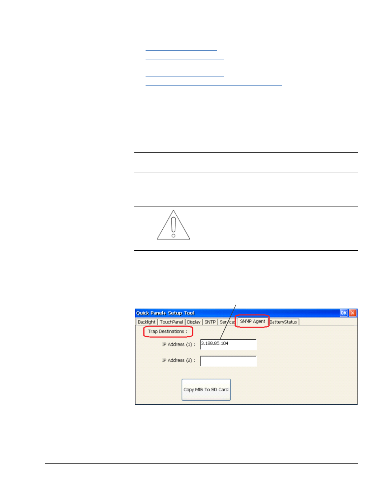
3.14.1 Configure Trap Destinations
TRAP Destinations are configured through the QuickPanel+Setup Tool by providing the
IP Address of the SNMP Manager to which Traps should be sent. The user can configure
two different Trap Destinations (IP Addresses).
Note If you do not want to be notified of Traps, you do not need to configure Trap
Destinations.
➢➢ To configure Trap Destinations
If Trap Destination(s) is/are configured after
enabling the SNMP Agent on the device, it is highly
recommended that you disable and then re-enable
the SNMP Agent service on the device.
Attention
1. From the Start menu, select System, open the QuickPanel
select the SNMP Agent tab.
2. Configure the Trap destination(s) of the SNMP Manager.
+
Setup Tool, and
3. Click OK to save the changes.
Close the QuickPanel
+
Setup Tool, then re-open the tool to view the configured Trap
Destination details from the SNMP Agent tab.
Software GFK-2847R 49
For public disclosure
Page 50

3.14.2 Enable or Disable SNMP Agent
Click Copy MIB To SD Card.
SNMP communication disabled by default on the QuickPanel+ device for security
purposes. To enable or disable SNMP communication using the QuickPanel
+
OS Utilities
Settings tool refer to the procedure Enable or Disable SNMP Agent.
Note Enabling or disabling SNMP communication is a one-time user configuration.
3.14.3 Export MIB to SD Card
With the SNMP Agent is enabled on the QuickPanel+device, export the QuickPanel
Management Information Base (MIB) QuickPanelMIB.mib file to a SD Card.
It is highly recommended that you pre-load GE
MIBs (GEIP-SMI.txt and GEIP-PRODUCTS-MIB.
txt in sequence) prior to loading the QuickPanelMIB.
mib file into SNMP Managers to avoid any MIB
compiler errors.
Contact technical support or download the MIBs
Attention
GEIP-SMI.txt and GEIP-PRODUCTS-MIB.txt
from the Support Site and QuickPanelMIB.mib can
be copied from the QuickPanel
+
device by
performing the following procedure.
+
➢➢ To export the MIB to a SD Card
1. Insert a working SD Card into the external card slot on the QuickPanel
2. From the Start menu, select System, open the QuickPanel
+
Setup Tool, and
select the SNMP Agent tab.
3. Copy the MIB file to the SD Card.
+
device.
50 GFK-2847R QuickPanel⁺ Operator Interface User Manual
For public disclosure
Page 51
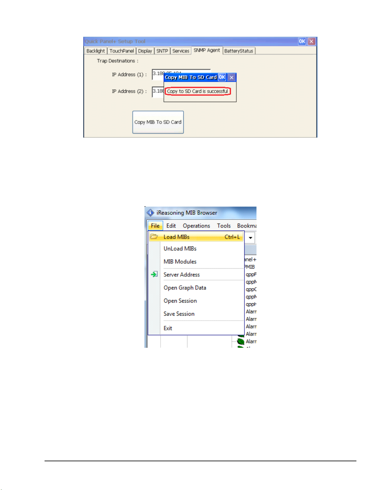
A dialog box displays when the copy is successful or if a failure occurs.
3.14.4 Load MIB into SNMP Manager
After successfully exporting the MIB to a SD Card, archive the QuickPanel+MIB file to a
folder on a machine running with SNMP Manager.
➢➢ To load the MIB into the SNMP Manager: from the SNMP Manager tool File
menu, select Load the MIBs.
Loading MIBs in 3rdParty SNMP Manager Tool
If there are no errors, the MIB will be loaded successfully and the SNMP Manager will be
ready for communication with QuickPanel
Software GFK-2847R 51
For public disclosure
+
device operating as a SNMP Agent.
Page 52

3.14.5 Data Types Mapping between PME Project and SNMP
When you configure HMI tags in a PME project and you would like to use them in SNMP
communication, all of the HMI tags are mapped to the corresponding data type in SNMP
as listed in the following table. To verify this, review the Sequence of HMI Tags object in
the MIB file.
PME VIEW Data Types SNMP Data Types
BOOL INTEGER
DINT INTEGER
LREAL DISPLAYSTRING
STRING DISPLAYSTRING
Note The PME VIEW LREAL data type is mapped to DISPLAYSTRING to retain the
data intact.
You can continue to use the data type override/suffix mechanism in PME for the LREAL
data type to represent a INT/DINT if you have configured the data type for driver
variables. This enables you to map to the DISPLAYSTRING data type in the SNMP
communication as well.
For example, for the GE SRTP driver, you can override the IO Address of LREAL
variable LREALVar data type as %R100[INT]. This maps LREALVar to
DISPLAYSTRING in the MIB file.
52 GFK-2847R QuickPanel⁺ Operator Interface User Manual
For public disclosure
Page 53

3.14.6 Establish SNMP Communication
SNMP communication requires that both the
+
device and the SNMP Manager
Attention
QuickPanel
running on a machine are connected on a valid
Ethernet network.
➢➢ To establish SNMP communication with the QuickPanel
1. Download the Project to the network connected QuickPanel
+
device
+
device and start
Runtime.
2. Configure the Trap Destinations with the IP Address of the SNMP Manager.
Note If you do not want to be notified of Traps, you do not need to configure Trap
Destinations.
3. Enable a SNMP Agent.
4. Export the MIB to a SD Card.
5. Auto-discover or connect the QuickPanel
+
SNMP Agent from the SNMP Manager.
Once connected, load the MIB to the SNMP Manager tool.
The SNMP Manager communicating with QuickPanel
Tags and receive Alarms/Trap notification from the QuickPanel
+
device can query values for HMI
+
device operating as a
SNMP Agent.
Tip � If you get out of sequence in the steps for configuring Traps and starting the
SNMP service to establish the SNMP communication, enable or disable the SNMP Agent
again using the QuickPanel
+
OS Utilities Setting tool.
Software GFK-2847R 53
For public disclosure
Page 54

Notes
54 GFK-2847R QuickPanel⁺ Operator Interface User Manual
For public disclosure
Page 55

4 Pre-installation Checks
This chapter provides information and procedures to perform pre-installation checks of
the QuickPanel
Before installing and using the QuickPanel
• Unpacking and Inspection
• Basic Setup
• Initial Startup
• Runtime Setup
• Firmware Updates
• Shutdown
4.1 Unpacking and Inspection
Upon receipt of the QuickPanel+Operator Interface, carefully inspect all shipping
containers for damage. If any part of the system is damaged, notify the carrier
immediately. Save the damaged shipping container for inspection by the carrier. It is the
consignee’s responsibility to register a claim with the carrier for damage incurred during
shipment.
+
Operator Interface.
+
, complete the following procedures:
For phone numbers and email
addresses, refer to the section,
Contact Information.
After unpacking the unit, record all serial numbers. These are needed to contact
Customer Care during the warranty period. Save all shipping containers and packing
material for future transport or shipping. Verify that all system components have been
received and agree with the order. If the system received does not agree with your order,
contact Customer Care.
Before initial powerup, inspect the unit for loose or damaged components. If damage is
found (such as bent component leads or loose components), contact GE Intelligent
Platforms for additional instructions.
Do not apply power to the unit if it has visible
damage. Applying power to a unit with damaged
components may cause additional damage.
Caution
Pre-installation Checks GFK-2847R 55
For public disclosure
Page 56
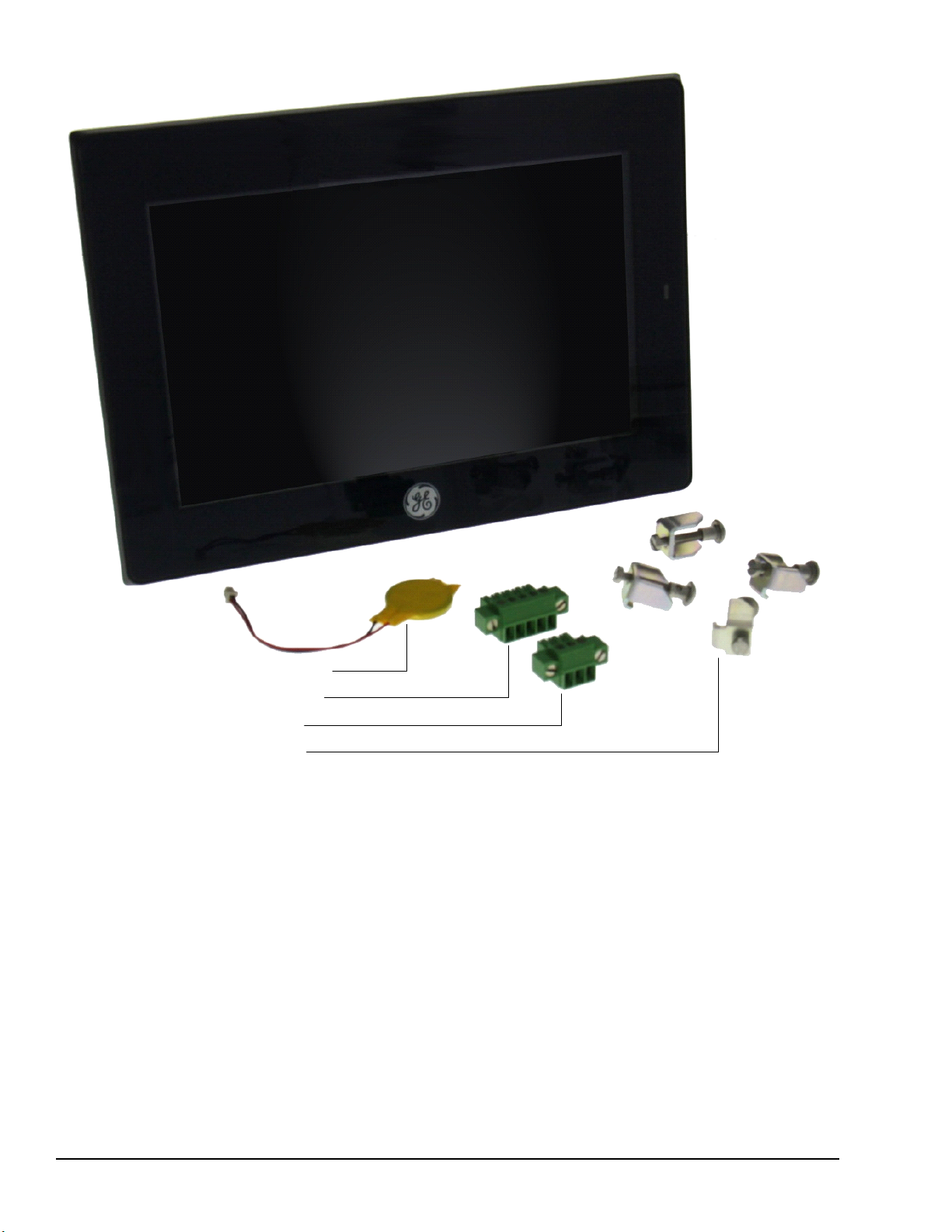
Battery (Qty 1) (pre-installed)
Serial Port Connector (Qty 1)
Power Connector (Qty 1)
Mounting Brackets (Qty 4)
Protective Sheet (Qty 1) (not shown)
Gasket (Qty 1) (not shown, pre-installed)
QuickPanel
+
Operator Interface
IC755CxWxxCDx Example Package Contents
56 GFK-2847R QuickPanel⁺ Operator Interface User Manual
For public disclosure
Page 57
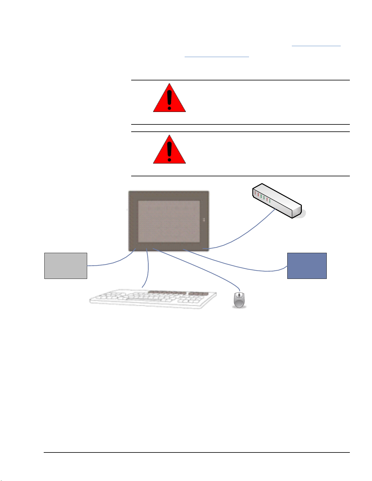
4.2 Basic Setup
Power Supply
Optional Ethernet
Connection
Optional USB Keyboard and Mouse
Serial I/O
Optional Serial I/O
The QuickPanel+Operator Interface is shipped ready for use after initial configuration.
To power up the unit, connect a dc power supply using the supplied quick-connect plug.
Depending on the application, you may also want to connect and configure optional input
devices, communications ports, and expansion adapters.
To avoid personal injury or damage to equipment,
ensure that the dc supply is disconnected from
power and the leads are not energized before
Warning
attaching them to the unit's power supply plug.
If this equipment is used in a manner not specified
by the manufacturer, equipment protection may be
impaired.
Warning
Basic Setup Diagram
Pre-installation Checks GFK-2847R 57
For public disclosure
Page 58

4.3 Initial Startup
M2.5
Mounting clamps
M2
Screw clamps
Power Connector
FG
GND +24 V dc
You will need the following:
• Safety Extra Low Voltage (SELV) and Limited Energy Circuit or SELVand Class 2
• The power terminal block is supplied with the product. For voltage and requirements,
• The mating power terminal block supports stranded 30 to 14 AWG
• At a minimum, the cable must be rated for 75°C (167 °F) or more.
• USB-compatible keyboard (optional)
• USB-compatible mouse (optional)
4.3.1 Connecting Input Power
➢➢ To connect input power
1. Verify that the power cable is not energized.
2. Loosen the screw clamps on the mating power
dc power supply.
refer to the Input Power specifications in the table, General Specifications.
(0.05 to 2.00 mm
2
) wires. The user calculates proper gauge wiring for current
carrying capacity and loss according to local regulations.
connector.
3. Strip the insulation from the power cables.
4. Secure the power cable to the mating connector,
noting polarity, and tighten the screw clamps. The
torque for the attaching screws is 0.3 Nm (2.66
in-lb).
5. Apply dc power to the unit. During normal startup
and operation, the QuickPanel
+
status LED indicator
displays as follows:
• Solid amber while the QuickPanel
+
is starting
up
• Solid green during normal operation
6. Once power is applied, the QuickPanel
+
begins
initializing. The splash screen is the initial display.
➢➢ To skip running any programs included in
the StartUp folder: tap Don’t run Startup
programs. The Microsoft Windows Embedded
Compact 7 operating system starts automatically.
58 GFK-2847R QuickPanel⁺ Operator Interface User Manual
For public disclosure
Page 59

4.3.2 Initial Configuration
From the
Date and Time
Perform the following procedure during initial startup.
➢➢ To configure the QuickPanel
1. Tap Start
2. Configure the system clock.
3. From the Control Panel, double-tap System to configure a Network Device Name.
Many applications, including Proficy Historian, require a unique Device Name.
, point to Settings, then tap Control Panel.
+
display
It is recommended to set a unique Device Name
for the QuickPanel
+
to avoid future conflicts.
4. From the Control Panel, double-tap Network and Dial-up Connections to
5. Run the Backup Utility to save the settings.
4.4 Runtime Setup
To download an application to a QuickPanel+Operator Interface, set up a data link
between the unit and the development workstation. Refer to the section, Ethernet for
IC755CxS06RDx, IC755CxWxxCDx and IC755CxSxxCDx, and the PME online help,
Downloading a Machine Edition Project.
Attention
configure network settings.
Pre-installation Checks GFK-2847R 59
For public disclosure
Page 60

4.5 Firmware Updates
Update the unit to the most recent released version of the firmware, with the latest feature
upgrades and issues addressed. Firmware updates for the QuickPanel
Support website.
Note The firmware update will remove the application and change the IP Address of the
QuickPanel
Note The firmware package contains encrypted .nbo files. Use the PreUpdate.exe tool to
decrypt the .nbo files before using them for upgrade.
4.6 Shutdown
There are no specific dangers associated with a power failure or other unplanned
shutdown of the QuickPanel
user data can be retained in BBSRAM. Some operating system settings are retained only
with user intervention. Perform the following procedure to properly shut down the
QuickPanel
+
Operator Interface.
+
unit.
+
are available on the
+
unit. In general, programs are retained in flash memory and
➢➢ To shut down the QuickPanel
+
unit
1. Quit any programs that are running and wait for all file operations to complete.
2. If you have not changed operating system settings (for example, brightness or
touchscreen sensitivity), or do not want to save the changes, remove ac power from
the dc supply.
3. Run the Backup Utility to save changes to operating system settings. When the
Backup window displays Completed Successfully, remove power from the dc power
supply connected to the QuickPanel
+
unit.
60 GFK-2847R QuickPanel⁺ Operator Interface User Manual
For public disclosure
Page 61

5 Mounting and Installation
This chapter provides the following procedures to mount and install the QuickPanel
Operator Interface:
• Protective Sheet Installation
• Mounting Location
• Panel Mounting
• VESA Arm Mounting
• Battery Installation and Replacement
• Connectors
5.1 Protective Sheet Installation
➢➢ To install the protective sheet
1. Remove the protective film from the QuickPanel
2. Wipe the display unit of any dust or fingerprints.
3. Peel back a corner of the clear side of the protective sheet.
4. Begin applying the corner to the display screen.
5. Slowly apply the rest of the protective sheet, smoothing out as you go.
6. Peel the green curing film from the protective sheet.
+
display screen.
+
Mounting and Installation GFK-2847R 61
For public disclosure
Page 62

5.2 Mounting Location
Refer to the section,
Environmental Specifications.
When mounting the QuickPanel+Operator Interface, make sure the mounting area allows
room to insert and remove the SD card, cables, and mounting brackets. Select a location
that allows natural convection air flow from bottom to top of the QuickPanel
Do not mount the QuickPanel
+
at an angle more than 30° from the vertical, as illustrated
+
enclosure.
in the following figure.
Mounting Angle
62 GFK-2847R QuickPanel⁺ Operator Interface User Manual
For public disclosure
Page 63

5.3 Panel Mounting
To mount the QuickPanel+in an enclosure, you will need the following equipment:
• One #2 Phillips head screwdriver
• Mounting brackets (supplied)
The mounting holes for IC755CxS06RDx, IC755CxW07CDx, and IC755CxS10CDx are
located on the top and bottom sides of the unit.
IC755CxS06RDx Mounting Holes
IC755CxW07CDx Mounting Holes
Mounting and Installation GFK-2847R 63
For public disclosure
Page 64

IC755CxS10CDx Mounting Holes
The IC755CxS12CDx and IC755CxS15CDx mounting holes are located on the top,
bottom, and sides of the unit.
IC755CxS12CDx Mounting Holes
64 GFK-2847R QuickPanel⁺ Operator Interface User Manual
For public disclosure
Page 65
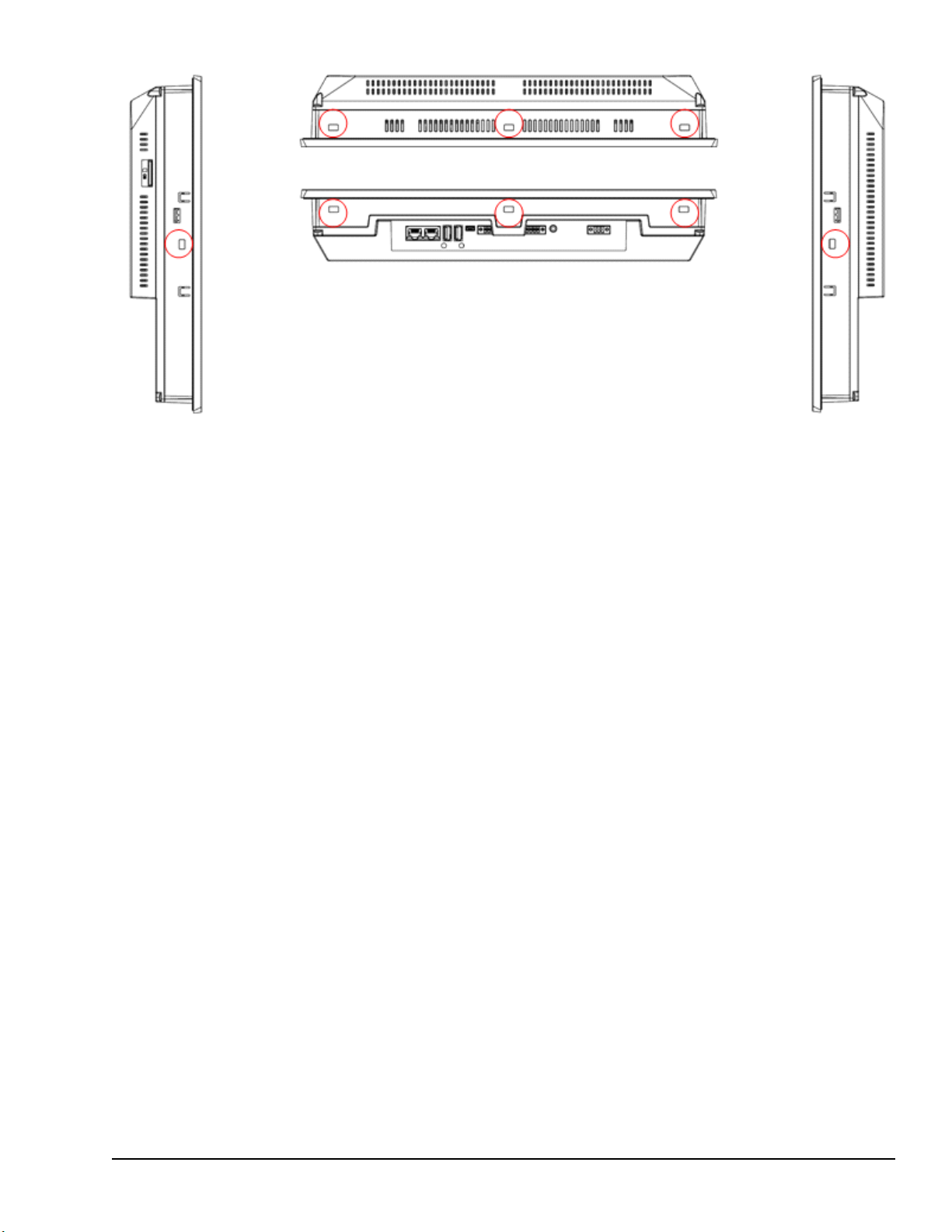
IC755CxS15CDx Mounting Holes
Mounting and Installation GFK-2847R 65
For public disclosure
Page 66

5.4 Mounting and Installation Procedure
Panel Thickness:
1.0 to 5.0 mm
(0.04 to 0.20 in)
128.50 mm (5.06 in)
183.50 mm (7.22 in)
Panel Thickness:
1.6 to 5.0 mm
(0.06 to 0.20 in)
266 mm (10.47 in)
210 mm (8.27 in)
Panel Thickness:
1.6 to 5.0 mm
(0.06 to 0.20 in)
228 mm (8.98 in)
302 mm (11.89 in)
Panel Thickness:
1.6 to 5.0 mm
(0.06 to 0.20 in)
379 mm (14.92 in)
305 mm (12.01 in)
Observe the following guidelines to properly mount and install the QuickPanel+Operator
Interface:
• The enclosure should be of metal material.
To order replacement gaskets,
refer to the part number listed
in Appendix B.
• The metal enclosure panel should ensure proper thickness and rigidity suitable to
minimize impact to the QuickPanel
• The recommended torque for the plastic back cover and interior metal cover for the
10, 12, and 15” QuickPanel
+
serial port DIP Switches is 0.5 Nm (4.4 in-lb).
• To avoid gasket degradation, limit repeated insertions or removals of the unit and
retightening of the mounting clips. For full protection, always use a fresh gasket.
• The unit will not fit through the cutout with any cables connected, or with the power
supply plug inserted in the socket.
Caution
+
unit.
display units that is accessed for panel updates and
When installing the QuickPanel+into the panel, pay
careful attention while handling the unit so it does
not drop and damage the unit.
➢➢ To install the QuickPanel
1. Cut an opening in the panel according to the specifications in the following figures.
Note Panel cutout tolerances are +0.50, –0.00 mm (+0.02, –0.00 in).
IC755CxSO6RDx or IC755CxW07CDx
Panel Cutout Dimensions
+
IC755CxS10CDx Panel Cutout Dimensions
66 GFK-2847R QuickPanel⁺ Operator Interface User Manual
For public disclosure
IC755CxS12CDx Panel Cutout Dimensions
IC755CxS15CDx Panel Cutout Dimensions
Page 67

2. Verify that the gasket is present and properly seated in the bezel channel located on
the sides of the unit.
3. Insert the QuickPanel
+
into the mounting panel cutout.
4. Insert the hook of the mounting bracket into the mounting hole as displayed in the
following figure.
5. Tighten the screws on the mounting bracket in a clock-wise direction.
Torque Range for Mounting Clamp Screws
Display Unit Torque Range
IC755CxS06RDx 0.3 Nm (2.66 in-lb)
IC755CxW07CDx 0.3 Nm (2.66 in-lb)
IC755CxS10CDx 0.7 Nm (6 in-lb)
IC755CxS12CDx 1.0 to 1.2 Nm (8.9 to 10.6 in-lb)
IC755CxS15CDx 1.0 to 1.2 Nm (8.9 to 10.6 in-lb)
Mounting and Installation GFK-2847R 67
For public disclosure
Page 68
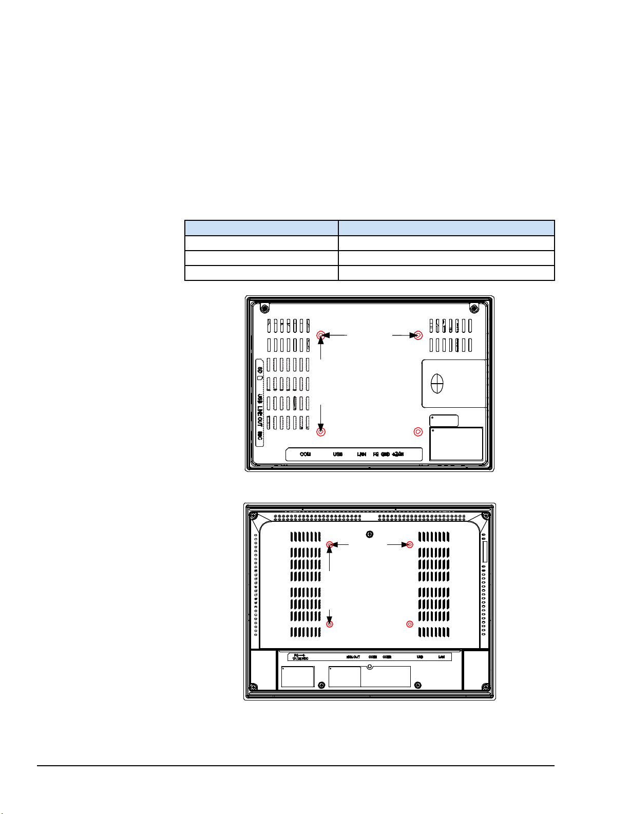
5.5 VESA Arm Mounting
75
m
m
7
5
m
m
75 mm
(2.95 in)
75 mm
(2.95 in)
100 mm
(3.94 in)
100 mm
(3.94 in)
The QuickPanel+unit can be installed on a commercially available Video Electronics
Standards Association (VESA) MIS-D arm, stand, or apparatus that complies with the
UL1678 standard.
Refer to the mounting arm
manual for instructions.
➢➢ To VESA mount the QuickPanel
back of the unit (displayed in the following figures).
The mounting holes for IC755CxS06RDx and IC755CxW07CDx attach with M4 screws
that are 6 mm (0.24 in) or less in length.
The mounting holes for IC755CxSxxCDx attach with M4 screws that are 8 mm (0.32 in)
or less in length.
Display Unit Torque Range
IC755CxS06RDx 0.7 to 0.8 Nm (6.2 to 7.1 in-lb)
IC755CxW07CDx 0.7 to 0.8 Nm (6.2 to 7.1 in-lb)
IC755CxSxxCDx 1.0 to 1.2 Nm (8.9 to 10.6 in-lb)
+
unit: use the mounting holes located on the
Torque Range for Mounting M4 Screws
IC755CxW07CDx or IC755CxS06RDx VESA Mounting Holes
68 GFK-2847R QuickPanel⁺ Operator Interface User Manual
For public disclosure
IC755CxSxxCDx VESA Mounting Holes
Page 69
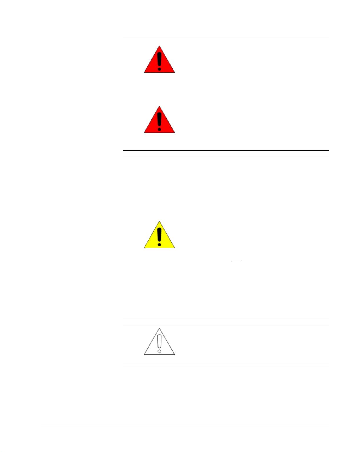
5.6 Battery Installation and Replacement
Batteries may present a risk of fire, explosion, or
chemical burn if mistreated. Do not crush,
disassemble, short-circuit, or dispose of in fire.
Use of batteries not specified for use with the
Warning
Warning
QuickPanel
explosion.
Do not recharge, disassemble, heat or incinerate
lithium batteries.
Dispose of lithium batteries in accordance with
federal, state, and local regulations. Be sure to
consult with the appropriate regulatory agencies
before disposing of batteries.
1) Replacing the battery should only be performed
by trained personnel and in a non-hazardous
location.
+
product may present a risk of fire or
Caution
Attention
2) If the QuickPanel
mounted, detach from the VESA arm when
replacing the battery.
3) The battery should only be replaced when the
unit is powered off.
4) Care should be taken to protect and insert the
battery with correct polarity.
5) Do not use any metallic item to remove the
battery (such as screwdrivers, knives, pliers, and so
forth).
6) Be careful to not drop the battery or any
associated screws into the unit.
7) Be careful of edges on internal sides of the
enclosure and frame.
The PC controller does not start automatically when
the battery is replaced in QuickPanel
Interface. After battery replacement, start the
controller using the #Command in the Proficy
Machine Edition (PME) runtime.
+
Operator Interface is VESA
+
Operator
Mounting and Installation GFK-2847R 69
For public disclosure
Page 70

5.6.1 IC755CxS06RDx
Battery Part Number
IC755ACCBATT
➢➢ To install or replace the battery for IC755CxS06RDx
Replace the battery for the IC755CxS06RDx only
with GE battery part number IC755ACCBATT.
Caution
1. Remove the battery cover by pressing down while sliding outward.
IC755CxS06RDx Battery Cover Removal
2. Connect the battery harness connector to the header, noting keyed orientation.
IC755CxS06RDx Battery Harness Connection
3. Verify that the positive (red) is down and negative (black) is up.
70 GFK-2847R QuickPanel⁺ Operator Interface User Manual
For public disclosure
Page 71
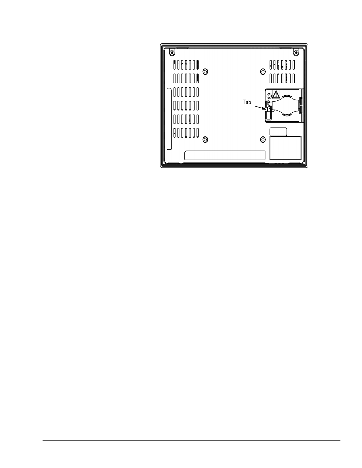
4. Wrap the harness connector around to match the following figure. Do not let the
harness connector go above the tab.
Harness Connector Orientation
5. Slide the battery cover into place, taking care not to pinch the harness connector.
Mounting and Installation GFK-2847R 71
For public disclosure
Page 72
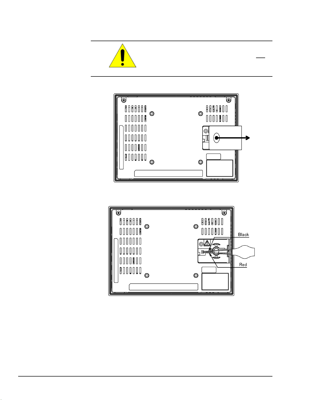
5.6.2 IC755CxW07CDx
Battery Part Number
IC755ACCBATT
➢➢ To install or replace the battery for the IC755CxW07CDx
Replace the battery for the IC755CxW07CDx only
with GE battery part number IC755ACCBATT.
Caution
1. Remove the battery cover by pressing down while sliding outward.
IC755CxW07CDx Battery Cover Removal
2. Connect the battery harness connector to the header, noting keyed orientation.
Battery Harness Connection
3. Verify that the positive (red) connection is down and the negative (black) connection
is up.
72 GFK-2847R QuickPanel⁺ Operator Interface User Manual
For public disclosure
Page 73
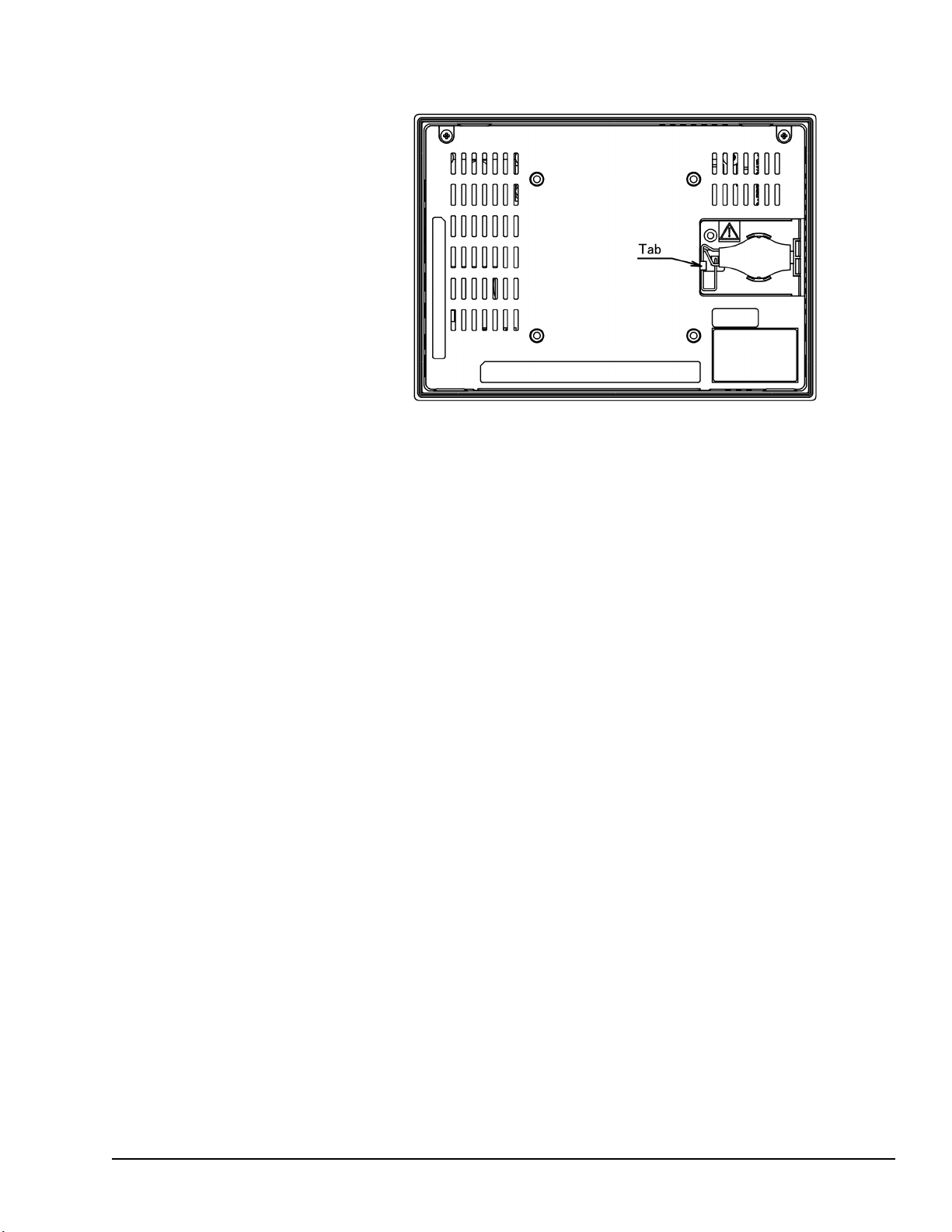
4. Wrap the harness connector around to match the following figure. Do not let the
harness connector go above the tab.
Harness Connector Orientation
5. Slide the battery cover into place, taking care not to pinch the harness connector.
Mounting and Installation GFK-2847R 73
For public disclosure
Page 74

5.6.3 IC755CxSxxCDx
➢➢ To install or replace the battery for the IC755CxSxxCDx
Replace the battery for the IC755CxSxxCDx only
with GE battery part number IC755ACCBATTNL.
Caution
1. Remove the screws (quantity 7) from the back cover.
IC755CxSxxCDx Screw Locations (Back Cover)
2. Gently press on either side tab to release the back cover.
Side Tab for Cover Release
3. Lift up and remove the back cover.
74 GFK-2847R QuickPanel⁺ Operator Interface User Manual
For public disclosure
Page 75

The battery will be exposed on the back of the unit.
Battery Part Number IC755ACCBATTNL
IC755CxSxxCDx Battery
4. Gently remove the coin battery and replace with a new one, noting the polarity of the
battery.
5. Replace the battery cover and tighten all screws to 0.5 Nm (4.4 in-lb).
Mounting and Installation GFK-2847R 75
For public disclosure
Page 76

5.7 Connectors
1 3
8 1
Yellow Green
5.7.1 Power Connector Pin-out for IC755CxS06RDx, IC755CxW07CDx, and IC755CxSxxCDx
Refer to the section Connecting
Input Power.
Refer to the section Ethernet
Port LED Operation.
Connector: Terminal Euro (Tyco Electronics 284539-3)
Mating Connector: (Tyco Electronics 284510-3)
Pin # Signal Name
1
2 GND
3 FG
†
IC755CxSxxCDx supports both +12 V dc or +24 V dc IN
+24 V dc
†
Pin-out
5.7.2 Ethernet for IC755CxS06RDx, IC755CxW07CDx, and IC755CxSxxCDx
The QuickPanel+display is equipped with 10Base-T/100-Base-TX Ethernet port(s).
Connect an Ethernet network cable (unshielded-twisted pair, CAT 5) to the unit through
the RJ-45 connector(s) on the bottom of the enclosure. LED indicators on the port
indicate channel status. The port can be accessed by Windows Embedded Compact 7
network communications or by your application.
5.7.2.1 Ethernet Port Details
Interface: Ethernet 10BASE-T/100BASE-TX
Pin #
1 TX+
2 TX3 RX+
4 NC
5 NC
6 RX7 NC
8 NC
Signal Name
Pin-out
Note Dual Ethernet ports are separate ports (only applicable to QuickPanel
IC755CxSxxCDx 10, 12, and 15" display units)
+
76 GFK-2847R QuickPanel⁺ Operator Interface User Manual
For public disclosure
Page 77

5.7.2.2 IP Address Setting
The QuickPanel+Operator Interface provides two methods to set an IP address:
• DHCP (Dynamic Host Configuration Protocol)
The network server assigns an IP address during QuickPanel
+
initialization. There
must be a DHCP server on the connected network for a valid IP address to be
assigned. Contact your network administrator to ensure correct DHCP server
configuration.
• Manual Method
Specify the numeric addresses obtained from your network administrator for the
QuickPanel
+
IP Address, Subnet Mask and Default Gateway (if applicable).
Note Run the Backup utility to save the settings.
Mounting and Installation GFK-2847R 77
For public disclosure
Page 78

5.7.3 Serial Port Details
Pin 1
Pin 5
5.7.3.1 IC755CxS06RDx
Adhere to the following guidelines:
• A terminal block is supplied with the unit.
• The mating terminal block supports stranded 30 to 14 AWG (0.05 to 2.00 mm
wires.
• At a minimum, the cable must be rated for 75°C (167 °F) or more.
• Secure the serial cable to the mating connector while noting signal orientation and
tighten the screw clamps.
• The torque for the attaching screws is 0.3 Nm (2.66 in-lb).
Connectors: Euro Terminal (Tyco Electronics 284539-5)
Mating Connectors: Tyco Electronics 284510-5
Serial Port COM1 Details
Interface: RS-232
COM1 Pin Details
Pin #
1 TXD
2 RXD
3 RTS
4 CTS
5 SGND
Signal Name
2
)
IC755CxS06RDx Serial Port COM1 Pin-out
78 GFK-2847R QuickPanel⁺ Operator Interface User Manual
For public disclosure
Page 79

5.7.3.2 IC755CxW07CDx
Pin 1
Pin 5
Adhere to the following guidelines:
• A terminal block is supplied with the unit.
• The mating terminal block supports stranded 30 to 14 AWG (0.05 to 2.00 mm
wires.
• At a minimum, the cable must be rated for 75°C (167 °F) or more.
• Secure the serial cable to the mating connector while noting signal orientation and
tighten the screw clamps.
• The torque for the attaching screws is 0.3 Nm (2.66 in-lb).
Serial Port COM1 Details
Interface: x1 RS-232
Connectors: Euro Terminal (Tyco Electronics 284539-5)
Mating Connector: (Tyco Electronics 284510-5)
COM1 Pin Details
Pin #
1 TXD
2 RXD
3 RTS
4 CTS
5 SGND
Signal Name
2
)
IC755CxW07CDx Serial Port COM1 Pin-out
Mounting and Installation GFK-2847R 79
For public disclosure
Page 80
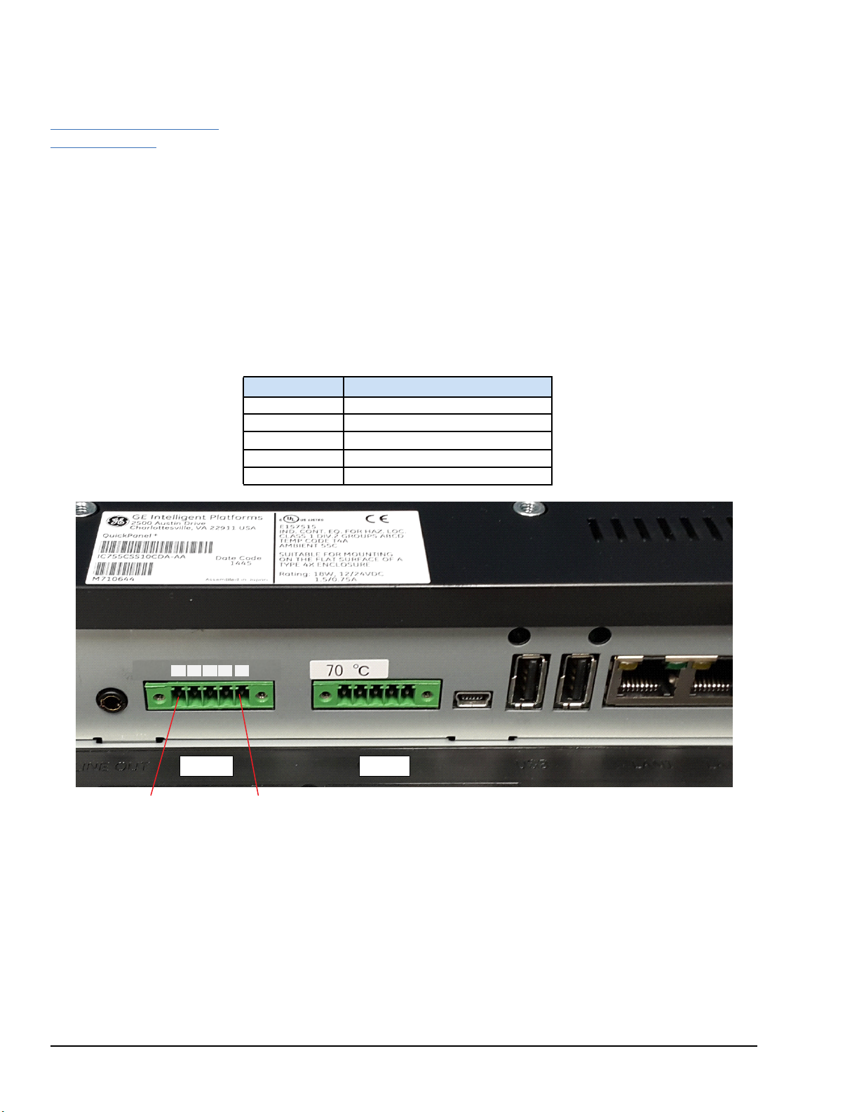
5.7.3.3 IC755CxSxxCDx
COM1 COM2
Pin 1 Pin 5
For an IC755CxS12CDA serial
port, refer to
Appendix C IC755CxS12CDA
Serial Port Details.
Adhere to the following guidelines:
• Terminal blocks are supplied.
• The mating terminal blocks support stranded 30 to 14 AWG (0.05 to 2.00 mm
2
)
wires.
• At a minimum, the cable must be rated for 75°C (167 °F) or more.
• Secure the serial cable to the mating connector while noting signal orientation and
tighten the screw clamps.
• The torque for the attaching screws is 0.3 Nm (2.66 in-lb).
Connectors: Euro Terminal (Tyco Electronics 284539-5)
Mating Connectors: Tyco Electronics 284510-5
Serial Port COM1 Details
Interface: RS-232C
COM1 Pin Details
Pin #
1 TXD
2 RXD
3 RTS
4 CTS
5 SGND
Signal Name
IC755CxSxxCDx Serial Port COM1 Pin-out
80 GFK-2847R QuickPanel⁺ Operator Interface User Manual
For public disclosure
Page 81

COM1 DIP Switch Setting for RS-232C
Pin 1 Pin 5
COM2
COM1
DIPSW Bit ON/OFF DIPSW Bit ON/OFF
1 OFF
1 OFF
2 OFF 2 OFF
3 OFF 3 OFF
SW2
4 OFF 4 OFF
5 ON 5 OFF
SW4
6 ON 6 OFF
7 OFF 7 OFF
8 ON 8 OFF
SW3
1 ON
2 ON 2 ON
3 OFF 3 ON
SW5
1 ON
4 OFF 4 ON
Serial Port COM2 Details
Interface: RS-232C/485 (default is RS-485 Half-duplex)
COM2 Pin Details
RS–232C RS–485
Pin #
Signal Name
Signal Name
(Full-duplex
†
)
1 TXD TXD+
2 RXD TXD-
3 RTS RXD+
4 CTS RXD5 SGND SG SG
†
Full-duplex RS–485 is backwards compatible to RS–422 mode.
‡
Pins 1-3 and 2-4 are connected internally.
Signal Name
(Half-duplex†)
‡
DATA+
‡
DATA-
‡
DATA+
‡
DATA-
IC755CxSxxCDx Serial Port COM2 Pin-out
Mounting and Installation GFK-2847R 81
For public disclosure
Page 82
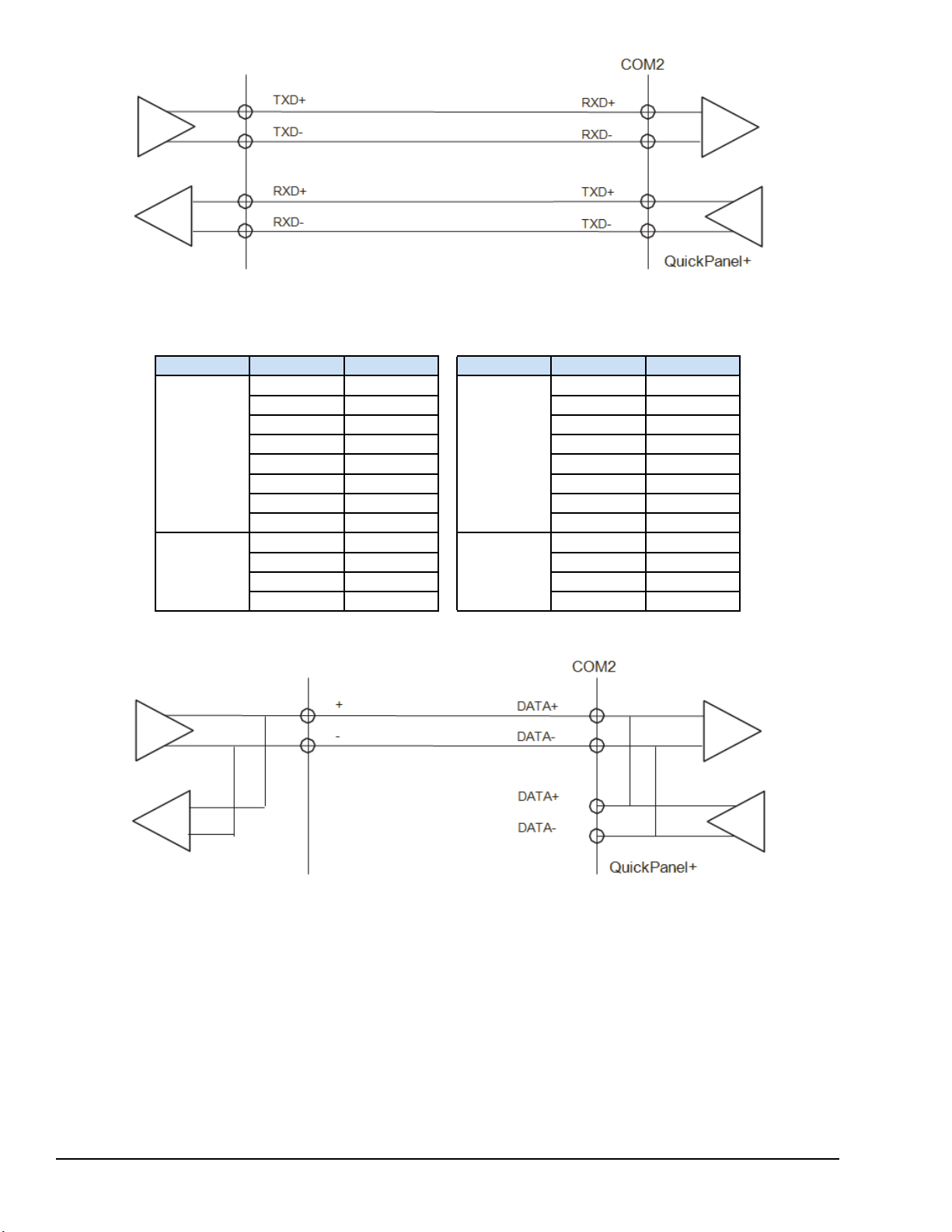
Example of Full-duplex (RS–422 Mode) Connection
COM2 DIP Switch Setting for RS–422
DIP SW Bit ON/OFF DIP SW Bit ON/OFF
1 OFF
1 ON
2 OFF 2 ON
3 OFF 3 OFF
SW2
4 OFF 4 OFF
5 ON 5 ON
SW4
6 ON 6 ON
7 OFF 7 OFF
8 ON 8 OFF
SW3
1 OFF
2 ON 2 OFF
3 OFF 3 OFF
SW5
1 OFF
4 OFF 4 OFF
Example of Half-duplex (RS–485 Mode) Connection
82 GFK-2847R QuickPanel⁺ Operator Interface User Manual
For public disclosure
Page 83
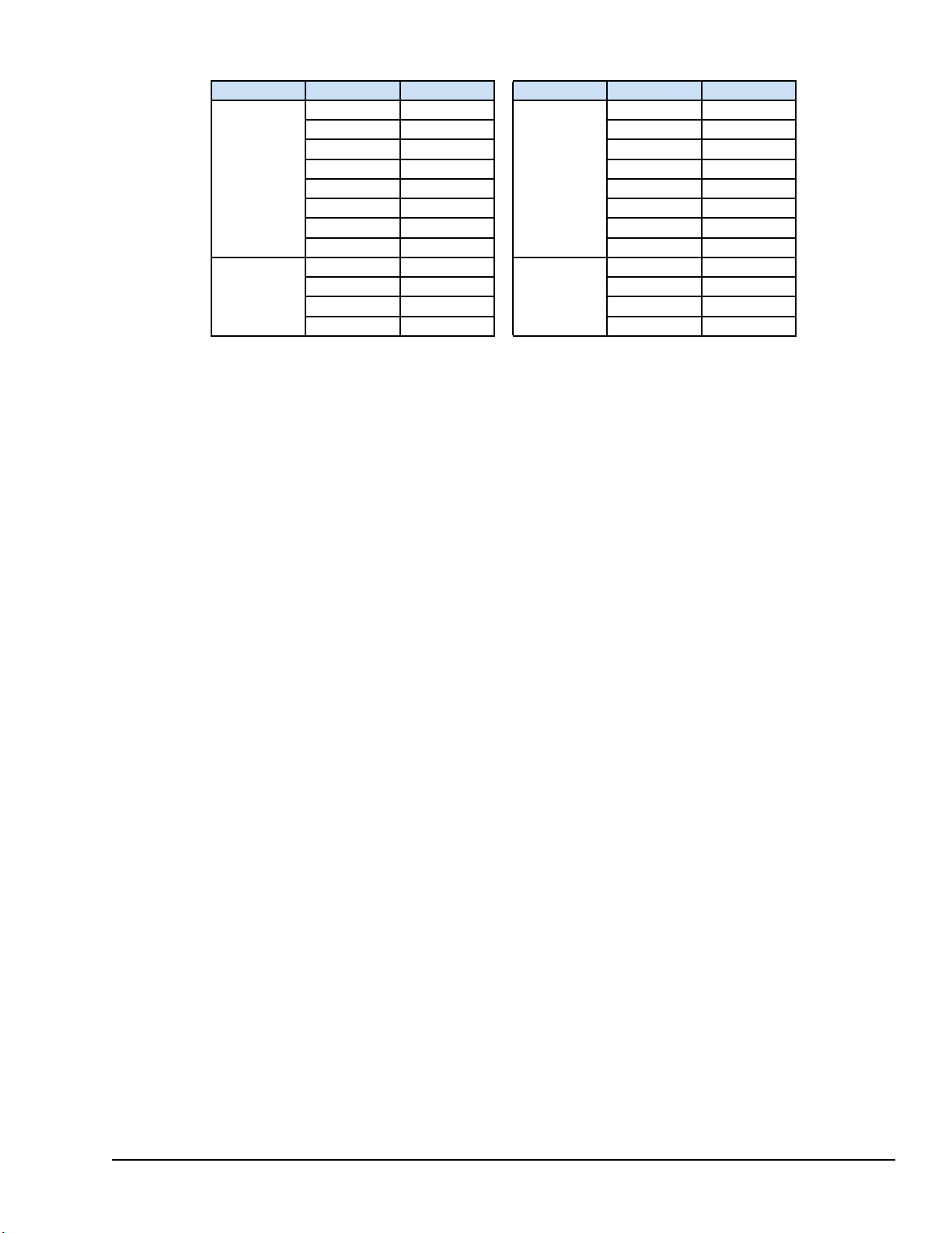
COM2 DIP Switch Setting for RS–485
DIPSW Bit ON/OFF DIPSW Bit ON/OFF
1 OFF
1 ON
2 OFF 2 ON
3 ON 3 ON
SW2
4 OFF 4 ON
5 ON 5 ON
SW4
6 ON 6 ON
7 OFF 7 OFF
8 ON 8 OFF
SW3
1 OFF
2 ON 2 OFF
3 OFF 3 OFF
SW5
1 OFF
4 ON 4 OFF
Mounting and Installation GFK-2847R 83
For public disclosure
Page 84
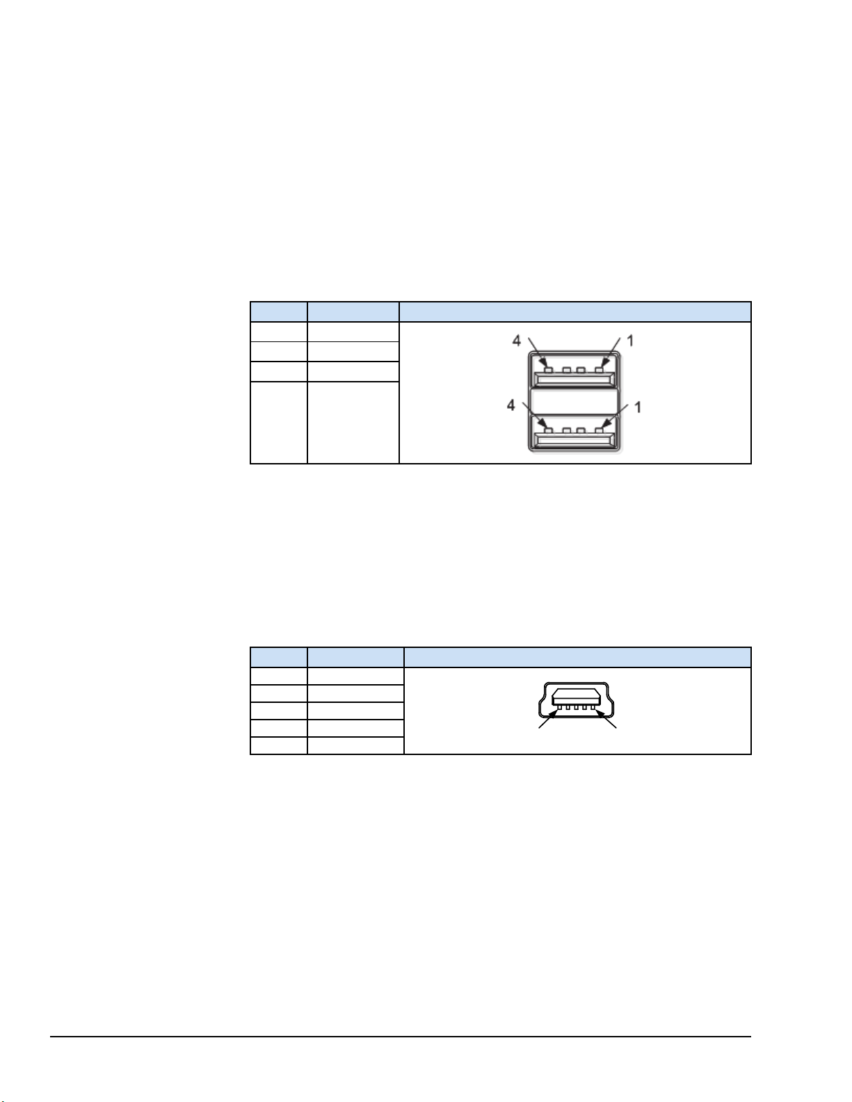
5.7.4 Universal Serial Bus (USB) Ports
5 1
5.7.4.1 USB Host Port Details for IC755CxS06RDx, IC755CxW07CDx, and IC755CxSxxCDx
The QuickPanel+has two full-speed USB 2.0 host ports. A variety of third party USB
peripheral devices are also available. Each connected USB device requires a specific
driver. The driver supplied with the QuickPanel
support; other devices require installation of the custom driver software.
Interface: USB 2.0
Number of Ports: Two
Connectors: Type-A connector
Maximum Supply Current: 0.5 A (per port)
+
is for optional keyboard or mouse
1
2
3
4
Signal Name
USB_VCC
USB_D-
USB_D+
USB_GND
Pin-out
Pin #
5.7.4.2 USB Device Port Details for IC755CxS06RDx, IC755CxW07CDx, and IC755CxSxxCDx
The USB device port allows the QuickPanel+Operator Interface to be used as Slave
device.
Interface: USB 2.0
Number of Ports: One
Connectors: Type-B Mini connector
Pin #
1 VCC
2 D3 D+
4 NC
5 GND
Signal Name
Pin-out
84 GFK-2847R QuickPanel⁺ Operator Interface User Manual
For public disclosure
Page 85
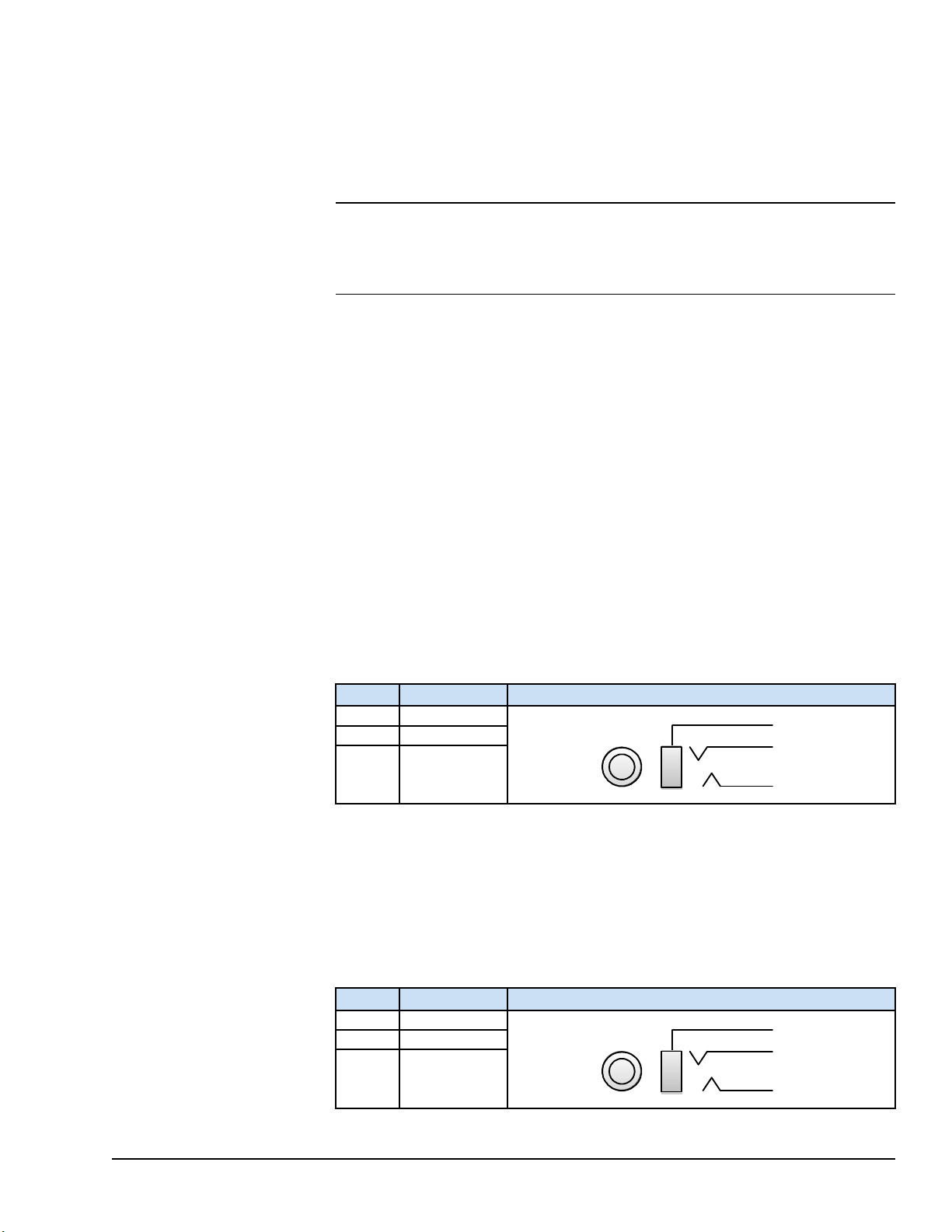
5.7.4.3 Serial USB and Ethernet USB Adapters for All Models
1
2
3
1
2
3
Using Adapters
Recommended adapters are as follows:
• Serial USB adapters based on FTDI chipset
• Ethernet USB adapters based on ASIX AX88179 or AX88772B
Note For serial USB adapters (USB to RS-485 and such), configure the correct COM
port depicted in the System Info tool and configure the same port in the Driver
configuration. In the System Info tool, the USB ports shown (COM3, COM4) are based
on the USB connection sequence on the device, and need to be configured accordingly.
5.7.4.4 Wi-Fi Support for All Models Using Adapters
Recommended USB wifi adapters based on the Ralink chipset are as follows:
• RT–2070
• RT–2870
• RT–3070
• RT–3071
• RT– 3072
5.7.5 Audio (LINE OUT) Details for IC755CxS06RDx, IC755CxW07CDx, and IC755CxSxxCDx
Interface: LINE OUT (stereo)
Number of Ports: One
Connectors: φ3.5 mm jack
Maximum output level: 1 Vrms
Pin #
1 GND
2 Lineout R
3 Lineout L
Signal Name
Pin-out
5.7.6 Audio (MIC IN) Details (Only Applicable to IC755CxS06RDx and IC755CxW07CDx)
Interface: MIC IN (monaural)
Number of Ports: One
Connectors: φ3.5 mm jack
Maximum output level: 250 mVrms
Pin #
1 GND
2 Lineout R
3 Lineout L
Mounting and Installation GFK-2847R 85
For public disclosure
Signal Name
Pin-out
Page 86
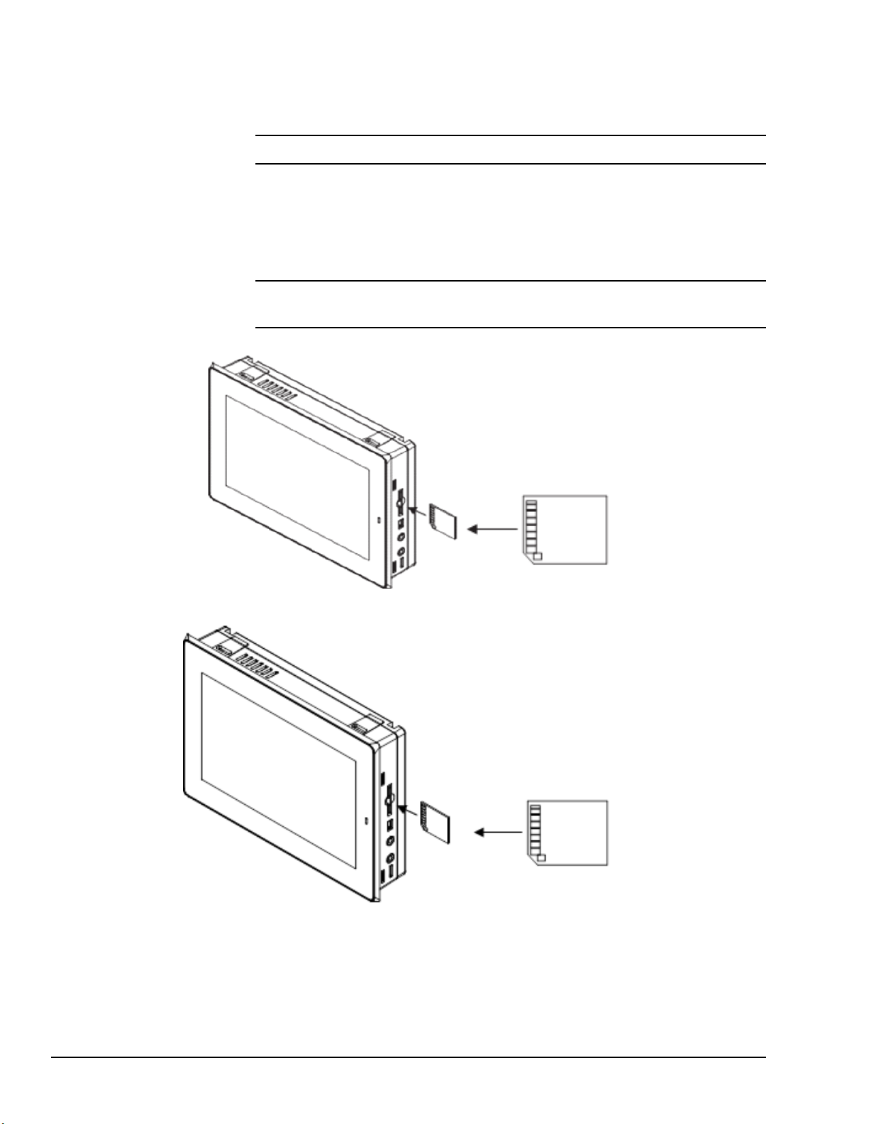
5.7.7 SD Card Slot and Storage
The QuickPanel+is equipped with one standard SD Card port. SD/SDHC memory cards
are supported. The SD card slot is spring-loaded for easy insertion and removal.
Note Micro SD slot is not supported on the 6” display unit (IC755CxS06RDx).
Connectors: SD card slot (push in-push out method)
Card support: SD/SDHC memory card
Maximum capacity: 32 GB
Note During insertion, observe the orientation of the SD card as displayed in the
following figures.
IC755CxS06RDx SD Card Location
IC755CxW07CDx SD Card Location
86 GFK-2847R QuickPanel⁺ Operator Interface User Manual
For public disclosure
Page 87
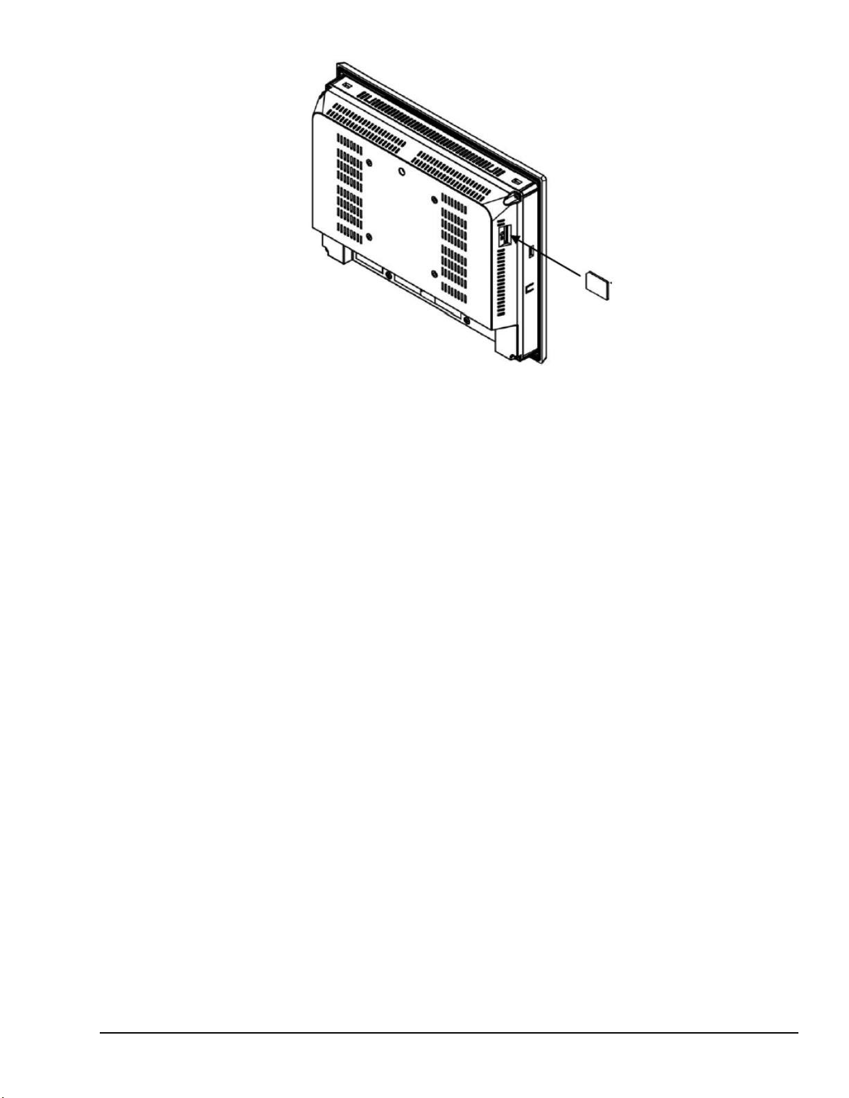
IC755CxSxxCDx SD Card Location
Mounting and Installation GFK-2847R 87
For public disclosure
Page 88

Notes
88 GFK-2847R QuickPanel⁺ Operator Interface User Manual
For public disclosure
Page 89

6 Operation
From the Setting backlight
brightness drop-down
menu, select a value
between 1 (lowest setting)
and 16 (highest setting).
6.1 Touchscreen Display
The QuickPanel+Operator Interface features a LED Backlight LCD touchscreen display
with two-point touch technology. The touch technology is based on projected capacitance
that allows finger tracking without pressured contact. It is conducive to smooth scrolling
and multi-touch gesturing capability. Display brightness and backlight operation can be
configured using the QuickPanel
Caution
Note IC755CxS06RDx (6” display) is an Analog Resistive touch display that does not
support two-point touch capability. Single point gestures such as swipe, pan, and
double-tap are supported.
+
Setup tool available in the program system menu.
Although we recommend the use of the protective
sheet, do not operate the touchscreen with any hard
materials, such as a screwdriver. This could damage
the touchscreen display.
6.1.1 Display Brightness Adjustment
➢➢ To adjust the brightness of the display
1. Open the QuickPanel
Backlight Display Properties window.
2. Set the backlight brightness value.
3. Tap OK to exit the QuickPanel+Setup Tool.
4. Run the Backup Utility to save the settings.
+
Setup Tool and select the Backlight tab to display the
Operation GFK-2847R 89
For public disclosure
Page 90

6.1.2 Display Backlight Configuration
Select Automatically turn
off the backlight. From the
drop-down menu, select a
time between 15 sec to 2 hr.
➢➢ To configure the display backlight
1. Open the QuickPanel
Backlight Display Properties window.
2. Set the backlight to automatically turn off in a specific amount of time.
3. Tap OK to exit the QuickPanel+Setup Tool.
4. Run the Backup Utility to save the settings.
+
Setup Tool and select the Backlight tab to display the
90 GFK-2847R QuickPanel⁺ Operator Interface User Manual
For public disclosure
Page 91

6.1.3 Touchscreen Re-calibration
Battery
Cover
Switch
The QuickPanel+touchscreen is shipped pre-calibrated. However, if there are any issues
with touchscreen responsiveness, it may need to be re-calibrated.
➢➢ To re-calibrate the touchscreen
1. Open the QuickPanel
2. Select the TouchPanel tab.
3. Select Recalibrate Touch Screen.
4. Select Recalibrate Touch Sensor.
Note During IC755CxS06RDx or IC755CxW07CDx touchscreen sensor
re-calibration, the user is prompted to activate a switch located in the battery
compartment. This is not applicable to any other display units.
5. Remove the battery cover and press the switch.
+
Setup tool.
Touchscreen Sensor Calibration Switch
6. Replace the battery cover.
Operation GFK-2847R 91
For public disclosure
Page 92

6.2 Keyboard Configuration
The QuickPanel+Operator Interface can be configured to use either or both a hardware
keyboard and a software emulation keyboard as operator data input devices. Typically, an
optional external hardware keyboard is used when in development mode, while the
included Soft Input Panel (SIP) is more applicable in an operational environment.
6.2.1 External Keyboard (Optional)
Any USB-compatible keyboard may be used as an input device for the unit. The USB
driver for the keyboard is included with the operating system and no configuration is
required. To use an external keyboard, connect the keyboard to the unit using the USB
cable.
6.2.2 Soft Input Panel
The Soft Input Panel (SIP) is a touchscreen keyboard that may be used in place of a
standard hardware keyboard. An icon in the system tray enables the user to view or hide
the SIP.
➢➢ To show or hide the SIP: from the system tray located on the task bar, tap the
icon and select Hide Input Panel.
6.3 Mouse
Note When visible, the SIP can be moved around the screen by dragging the title bar to
reveal parts of the screen that would be obstructed from view by the SIP.
Any USB-compatible mouse may be used as an input device for the unit. The USB driver
for the mouse is included with the operating system and no configuration is required. To
use an external mouse, plug it into the appropriate port.
92 GFK-2847R QuickPanel⁺ Operator Interface User Manual
For public disclosure
Page 93

6.4 Printing
Warning
USB-connected printers will violate the electrical
compliance ratings. They can only be used for
maintenance and are not supported as a standard
service.
The QuickPanel
inkjet printers. The printer can be connected by either USB (on models with USB ports)
or by a network shared printer over Ethernet. The control panel applet Printers is used to
configure the port connection and other general printing options.
For the fastest printing performance, select draft mode and portrait orientation, and
disable color for print settings. These settings also minimize the amount of memory
needed to print a document.
The built-in driver has a document spooling function to improve GUI performance. This
spooler supports only one document at a time. However, on an Ethernet connected printer,
the print server usually supports multiple documents in its queue. Windows Embedded
Compact 7 does not support the ability to observe which documents are queued up at the
printer.
For a list of printers that are compatible with that QuickPanel
the document Third Party Device Compatibility (KB8259).
+
Operator Interface supports printing with PCL v5 compatible laser and
+
Operator Interface, refer to
Operation GFK-2847R 93
For public disclosure
Page 94

6.5 Memory
6.5.1 DRAM Memory
The QuickPanel+Operator Interface is equipped with Dynamic RAM (DRAM). Part of
the DRAM is reserved for the Windows operating system and is not accessible by user
applications. The remaining memory is split between two functions: an object store for
temporary file storage and the main memory for running programs.
Typically, compressed programs stored in flash memory are expanded and moved to
DRAM for execution. Temporary storage of program variables or data files is also
provided by DRAM. Any data stored in DRAM is not retained through a power cycle or
restart.
The split between program memory and storage memory can be adjusted as necessary to
make more room for one or the other, depending on specific application needs. For
example, if an application is short of memory, alter the DRAM memory allocation from
the System Properties window.
Setting the Program Memory too low may prevent
additional applications from starting, or may cause
currently running applications to fail due to lack of
memory.
Caution
Setting the Storage Memory too low may prevent
the saving of files into the object store portion of the
file system, which may also cause application
failures.
For the QuickPanel
Storage Memory too high or to extreme limit may
make the device become unresponsive to launch any
applications or windows and it may also require a
power cycle. It is recommended that the Storage
Memory is set to a valid limit.
+
6” display unit, setting the
94 GFK-2847R QuickPanel⁺ Operator Interface User Manual
For public disclosure
Page 95

6.5.2 Memory Allocation Modification
➢➢ To change the memory allocation
1. From the Control Panel, double-tap System to display the System Properties
window.
2. From the Memory tab, drag the slider bar to divide into Storage and Program
memory. The amount of memory allocated to and used by each area is displayed in
the window. The blue slider bar indicates the current amount of unallocated SDRAM
and determines the boundaries within which the slider can move.
System Memory Slider Bar
Note Storage memory is limited to a maximum of 128 MB. Using the slider bar to
increase storage memory will provide more RAM-based storage in the folder \Object
Store.
3. Tap OK to apply the new setting.
4. Run the Backup Utility to save the settings.
Operation GFK-2847R 95
For public disclosure
Page 96

Notes
96 GFK-2847R QuickPanel⁺ Operator Interface User Manual
For public disclosure
Page 97
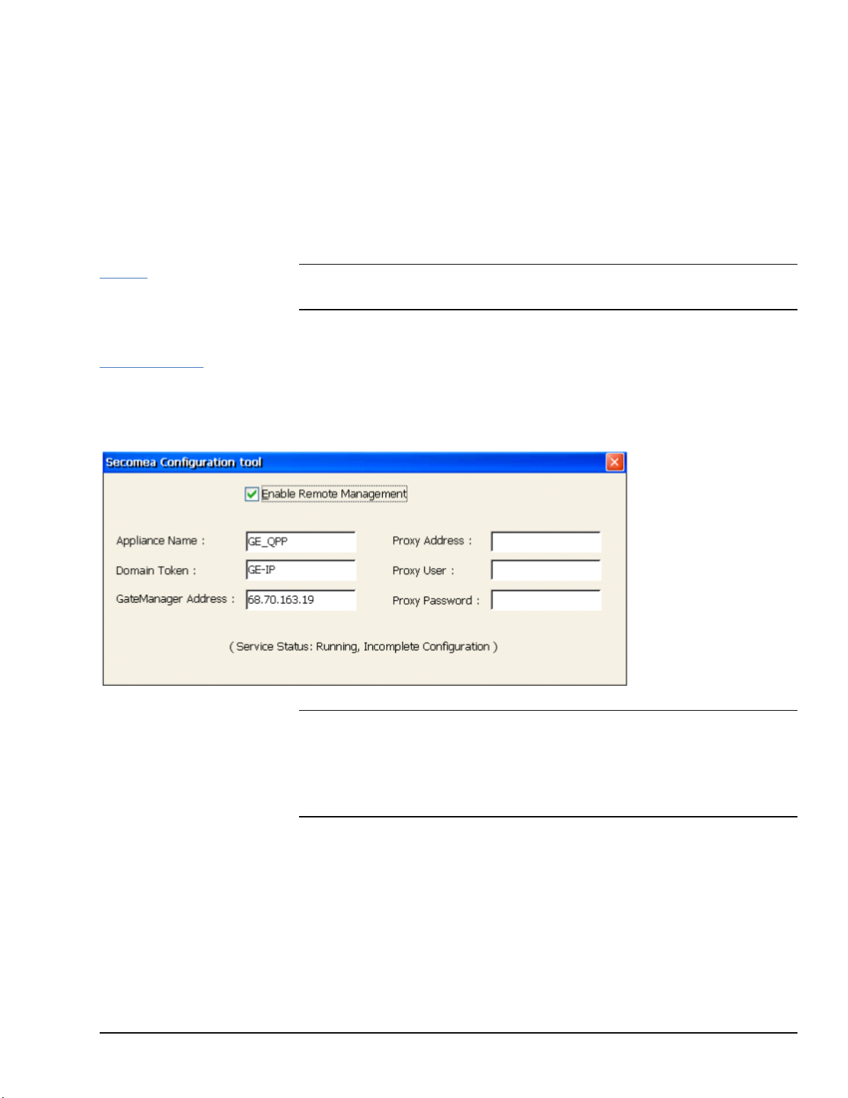
7 Secomea Security (Optional)
Select Enable Remote
Management and enter
the values provided to you
by the Secomea team.
7.1 Secomea Configuration Tool
The SiteManager™and its
and
Mobile
™
,
related GateManager
LinkManager
LinkManager
™
™
products are licensed, sold,
and supported by Secomea and
Secomea’s licensed
distributors. Additional
information, is available at
www.secomea.com.
Secomea SiteManager software (also known as the Secomea Configuration tool) is
+
installed on QuickPanel
configure and enable the QuickPanel
products. The Secomea Configuration tool enables the user to
+
device on the Secomea network.
Note It is recommended to have a Network Architect on-site and working with Secomea
team to enable this functionality.
➢➢ To access the Secomea Configuration tool and enable the QuickPanel
+
on the Secomea network
1. From the QuickPanel
+
Start menu, select Programs to display the Secomea
Configuration tool window.
2. Enable the QuickPanel
+
device on the Secomea network.
Note The Appliance Name can be any name but should be unique so that Secomea
network can identify the device.
Proxy Address allows the user to connect from their local network with firewall enabled
and blocking ports 80, 443, and 11444. The SiteManager will attempt to establish a
connection with and without proxy.
Secomea Security (Optional) GFK-2847R 97
For public disclosure
Page 98

7.2 Secomea Products
Activation and deployment of
the Secomea product features
is optional. SiteManager,
GateManager, and
LinkManager products are
licensed, sold, and supported
by Secomea and Secomea’s
licensed distributors.
QuickPanel
+
customers
wanting to activate licenses for
Secomea products can do so at
www.secomea.com.
+
The available Secomea SiteManager (embedded on QuickPanel
), GateManager, and
LinkManager products are described as follows:
SiteManager is a device-monitoring front-end feature for multiple industrial devices on
a location. Working with GateManager and LinkManager, it ensures uninterrupted and
secure access to remote devices over the Internet or a private Wide-area Network (WAN)
for all users.
LinkManager is an off-the-shelf software component in Remote Device Management
Solutions from Secomea that provides security for external programming and monitoring
applications. LinkManager Mobile provides similar functionality for mobile devices.
GateManager is the central component of Secomea’s Industry solution. The
GateManager M2M Server operates as a termination point for all LinkManagers and
SiteManagers. All connections and the encrypted traffic between LinkManagers and
devices controlled by SiteManagers are handled by the GateManager, where all events are
also logged.
Note The GateManager is typically offered as a service hosted by Secomea. Users will
receive an isolated domain on the GateManager and benefit from central hosting and
back-up by Secomea. Or, the user can host their own GateManager.
Additionally, other devices such as PLCs and PCs (in addition to the QuickPanel+) can be
added as new agents on the Secomea network to be part of Secured Communication using
the Add Agents feature in the SiteManager GUI. This can be achieved using extended
license feature from Secomea.
Note Secomea products installed throughout the application as suggested by the
following figure do not intrinsically provide the level of security associated with
firewalls. The network architect needs to satisfy himself or herself that the security level
required by the application is present in the overall implementation.
98 GFK-2847R QuickPanel⁺ Operator Interface User Manual
For public disclosure
Page 99
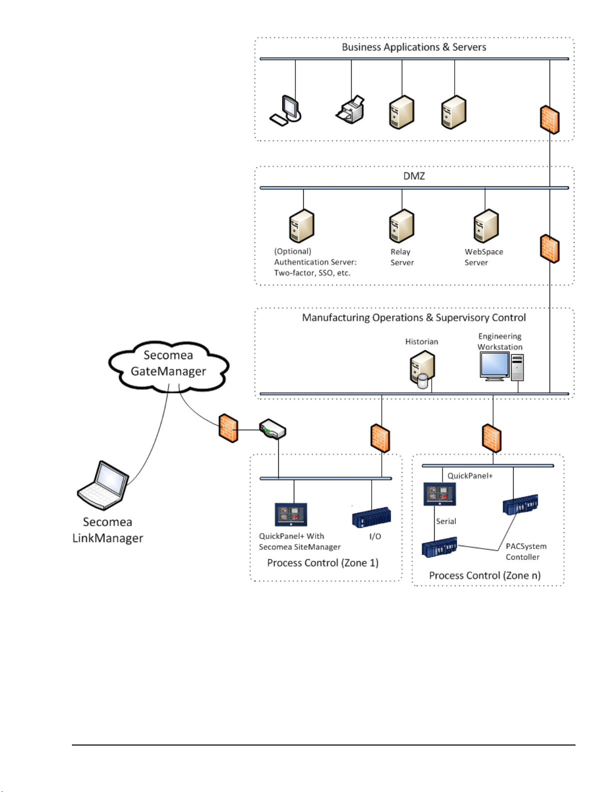
Secomea Products used with QuickPanel+in Application
Secomea Security (Optional) GFK-2847R 99
For public disclosure
Page 100

Notes
100 GFK-2847R QuickPanel⁺ Operator Interface User Manual
For public disclosure
 Loading...