

GE GTUP270EMWW, GTUP270GMWW, GTUP240EMWWGTUP240GMWW, GTUP240EMWW, GTUP240GMWW Service Manual
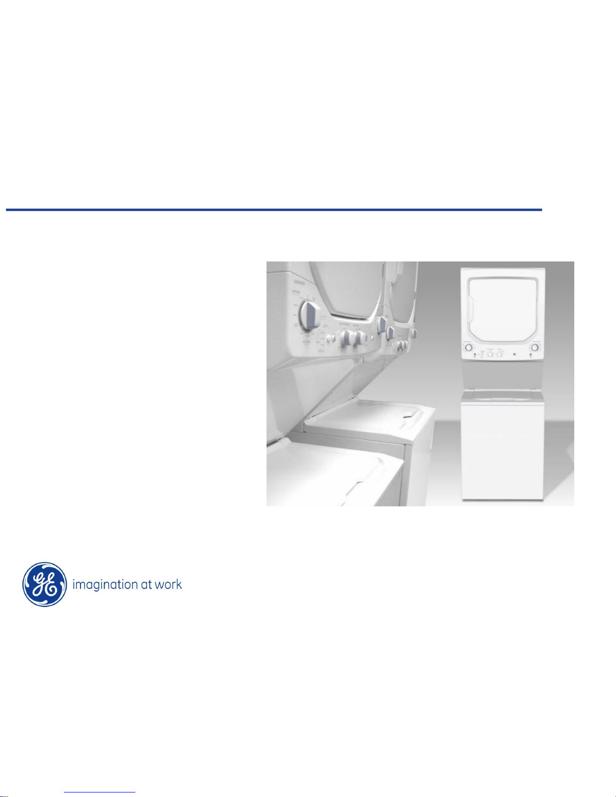
24” & 27” Unitized Laundry Centers
GTUP270EMWW
GTUP270GMWW
GTUP240EMWW
GTUP240GMWW

IMPORTANT SAFETY NOTICE
The information in this presentation is intended for use by individuals
possessing adequate backgrounds of electrical, electronic, &
mechanical experience. Any attempt to repair a major appliance may
result in personal injury & property damage. The manufacturer or seller
cannot be responsible for the interpretation of this information, nor can it
assume any liability in connection with its use.
WARNING
To avoid personal injury, disconnect power before servicing this product.
If electrical power is required for diagnosis or test purposes, disconnect
the power immediately after performing the necessary checks.
RECONNECT ALL GROUNDING DEVICES
If grounding wires, screws, straps, clips, nuts, or washers used to
complete a path to ground are removed for service, they must be
returned to their original position & properly fastened.

Copyright General Electric 2010
GE Factory Service Employees are required to use safety glasses with side
shields, safety gloves & steel toe shoes for all repairs.
Dyneema® Cut
Resistant Glove
Safety Glasses
must be
compliant with
ANSI Z87.1-2003
Prescription Safety Glasses
Plano Safety Glasses
Steel Toe Shoes
VR Gloves – provide shock protection
Copyright General Electric 2010
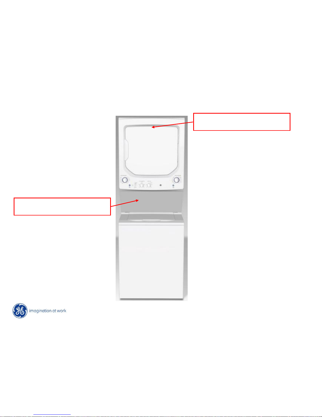
Model/Serial Tag
Located inside dryer on front panel
Mini-Manual
Taped on the inside of the service panel
Product Information

Copyright General Electric 2010
• Drum capacity 5.9 ft3
• Drum access area: 303 in
2
• Heater power : 5400W
• 4 drying cycles (Timed, Auto
Cottons, Easy care, Delicate)
• Auto cottons cycle available
• Wrinkle care option
• Exhaust max. length: 48 ft
• Drum capacity 5.7 ft3
• Drum access area: 234 in2
• Heater power : 4500W
• 3 drying cycles (Timed,
Permanent press, Delicate)
• No auto cottons cycle available
• No wrinkle care option
• Exhaust max. length: 48 ft
New 27” Old 27”
DRYER 27’’ Design Differences
Unitized Laundry Center
Product Weight 240 Lbs

Copyright General Electric 2010
• Capacity 3.18 ft
3
• Index rinse(w/basket spin) & Deep
rinse
• Adaptive fill and Manual Fill
capability
• ATC temperature control
• Washer Electronic Control
• LED status indicators
• Quick Release Lid Lock
• Capacity 2.7 ft
3
• Deep rinse only
• Manual fill capability
• Discrete water temperatures
• Washer Electromechanical
Timer
• Cycle indicator thru timer
• Slow release Lid Lock (ptc)
New 27” Old 27”
27” Washer Design Differences
Unitized Laundry Center

Copyright General Electric 2010
• Capacity 4.4 cu. ft .
• Drum access area: 150 in2
• 4 Heat levels available
• Delicate cycle available
• Lint filter in the door
• Front serviceable as per spec.
• EOC removed
• Height 3” taller
• Capacity 3.4 cu. ft .
• Drum access area: 133 in2
• 3 Heat levels available.
• No delicate cycle available
• Lint filter at the rear of the
drum
• Some parts require rear access
to service
• EOC signal
New 24”
Old 24”
DRYER 24’’ Design Differences
Unitized Laundry Center
Product Weight 214 Lbs
“End Of Cycle Signal”

Copyright General Electric 2010
24” Washer Design Diferences
• Capacity 1.87 ft
3
• Index rinse(w/basket spin) & Deep
rinse
• Adaptive fill and Manual Fill
capability
• ATC temperature control
• Washer Electronic Control
• LED status indicators
• Quick Release Lid Lock
• Capacity 1.75 ft3
• Deep rinse only
• Manual fill capability
• Discrete water temperatures
• Washer Electromechanical Timer
• Cycle indicator thru timer
• Mechanical Brake
• Transmission + I Motor
New 24” Old 24”
Unitized Laundry Center
Copyright General Electric 2010
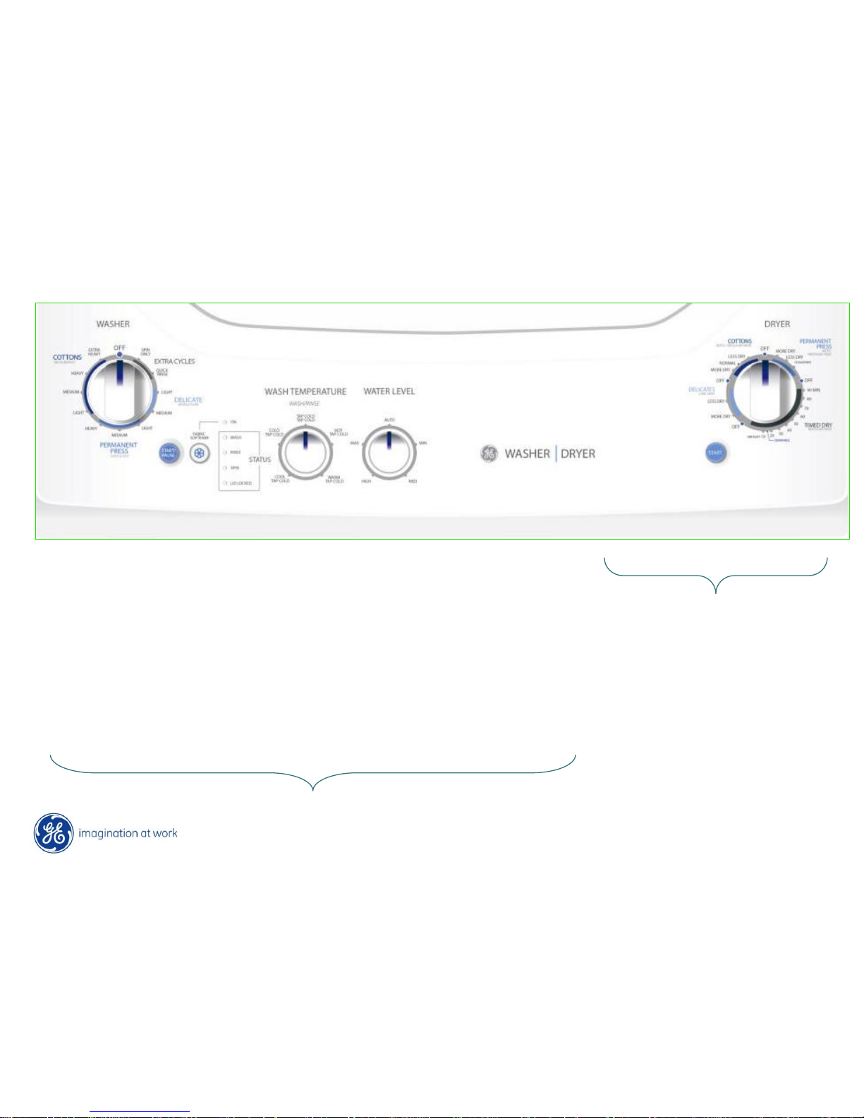
Water Level
• Automatic
(if Adaptive
Fill is needed)
• Minimum
• Medium
• High
• Maximum
T Board
2 buttons
• Start / Pause
• Options
5 Leds
• “Shower Rinse”
• “Deep Rinse”
• Wash (Indicator)
• Rinse (Indicator)
• Spin (Indicator)
Temperature
• Cold - 60
• Cool - 70
• Warm – 80
• Hot – 110
Programs
• OFF
• Heavy duty
• Whites
• Colors
• Easy care
• Delicates
• Speed Cycle
• Extra Spin
Start Button Timer
Product Controls
Washer Controls
Dryer Controls
Copyright General Electric 2010
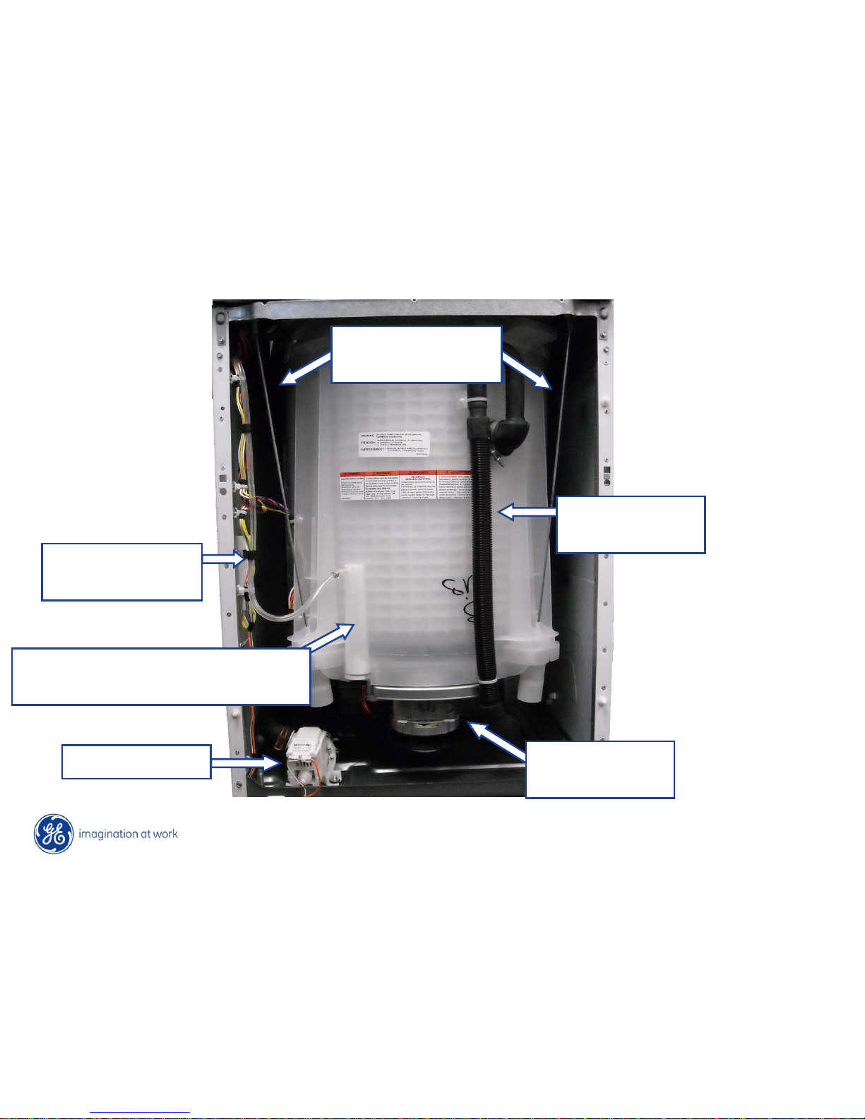
Washer Components
Over flow
pipe
Motor &
Transmission
Drain Pump
Motor
Capacitor
Suspension
Rods
Pressure Switch Dome & Hose
Copyright General Electric 2010
Gas Dryer Components
Motor &
Blower Assy
Gas Valve
Flame Detector
High Limit
Thermostat
Safety
Thermostat
Control Inlet
Thermostat
Outlet
Thermostat
Copyright General Electric 2010
Electric Dryer Components
Safety
Thermostat
High Limit
Thermostat
Control Inlet
Thermostat
Inner Heater
Coils
Outer Heater Coil
Copyright General Electric 2010
Control Panel Access
To access the service panel; remove the two Phillips screws at the top left and right of
the panel. Lift up on the panel and pull forward to release the panel from the cabinet.
The mini manual is taped to the backside of the service panel.
Mini
Manual
Copyright General Electric 2010
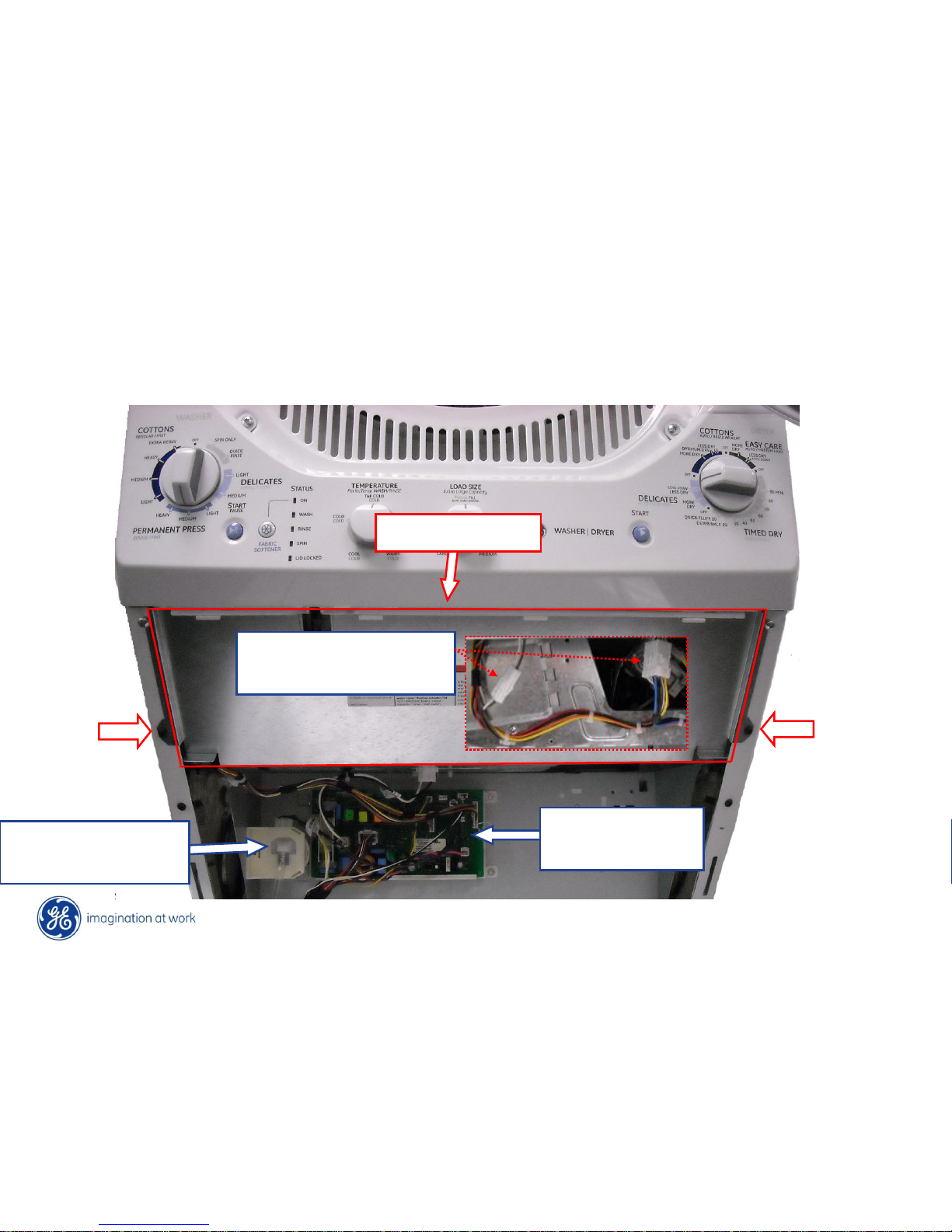
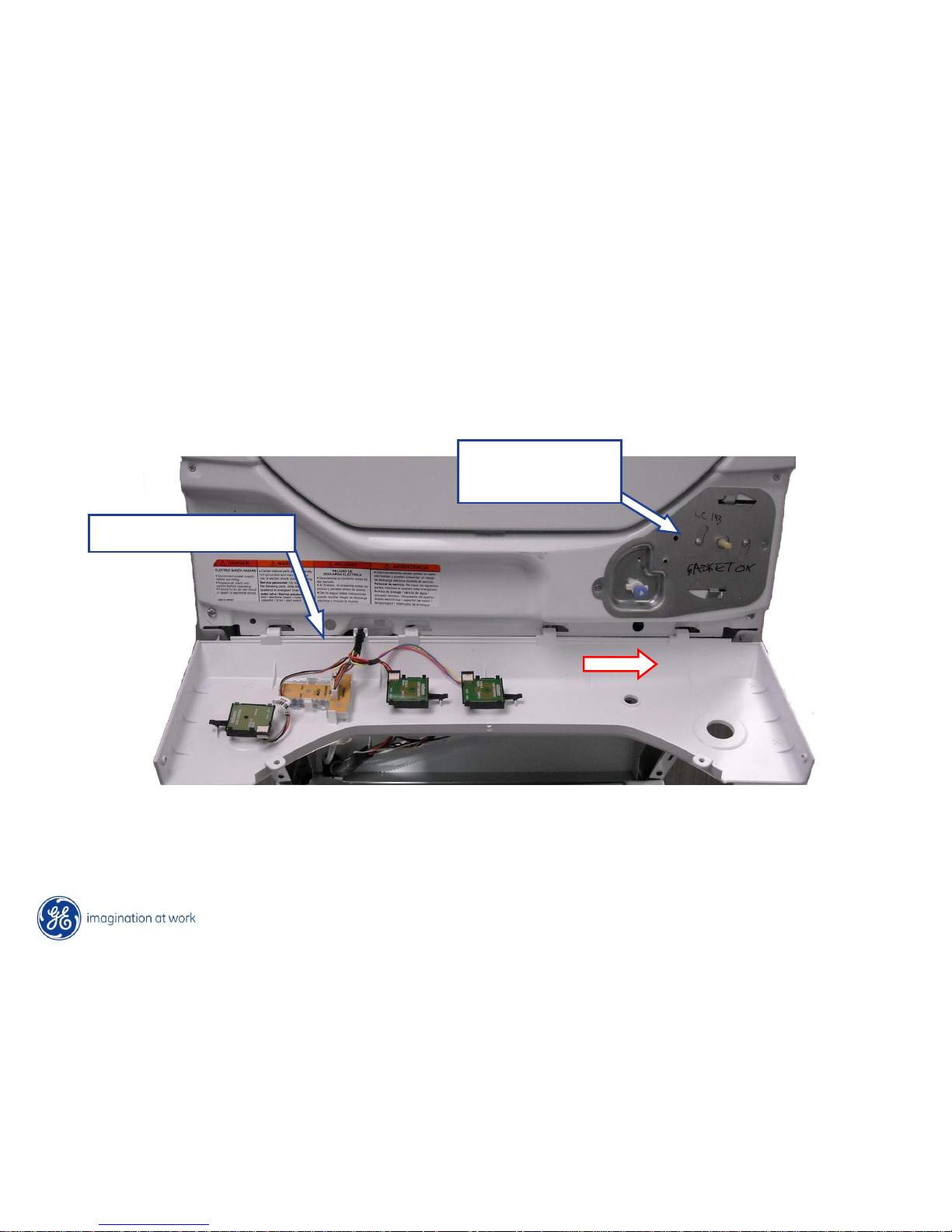
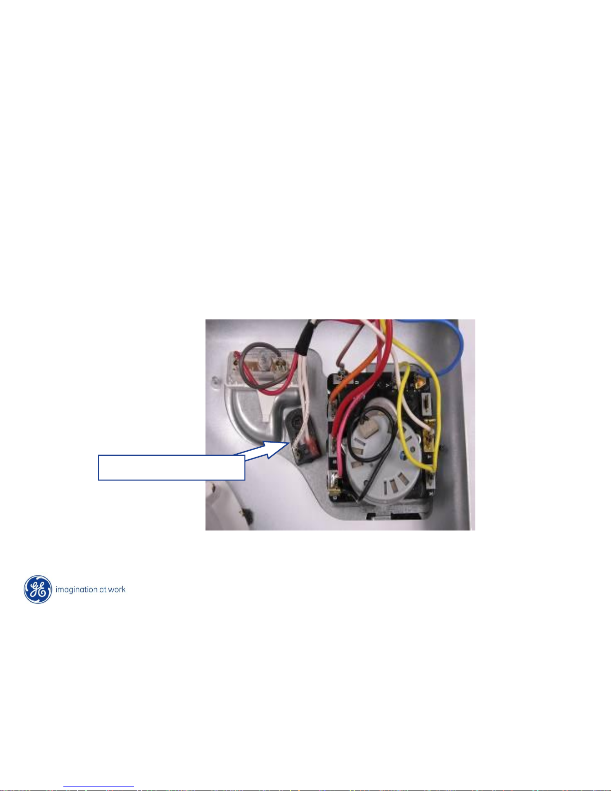
Control Panel Access
The washer control and pressure switch are accessible after removing the service panel.
To access the dryer harness wiring connectors; remove two Phillips screws from the
heat shield and pull the shield forward to remove.
Washer
Control Board
Water Pressure
Sensor
Dryer Harness
Connectors
Heat Shield

Copyright General Electric 2010
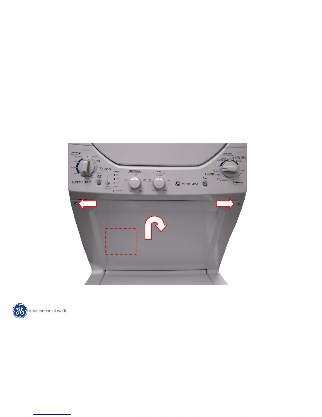
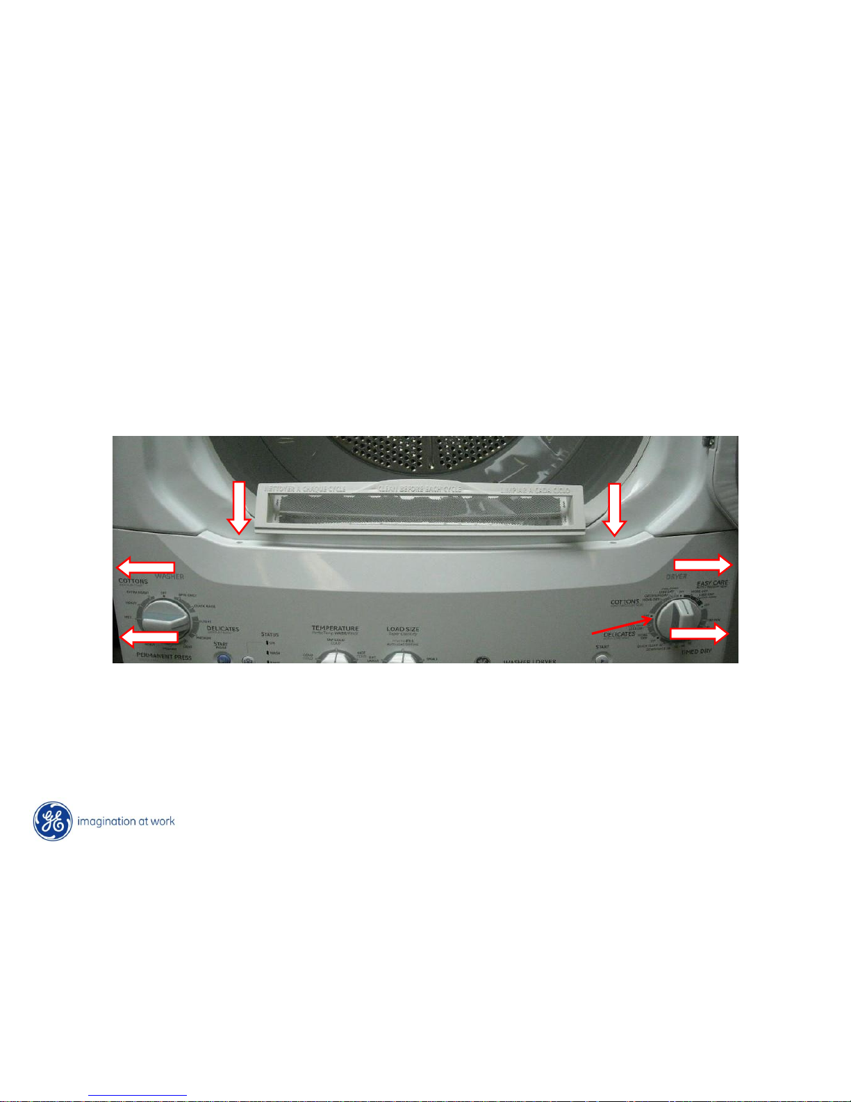
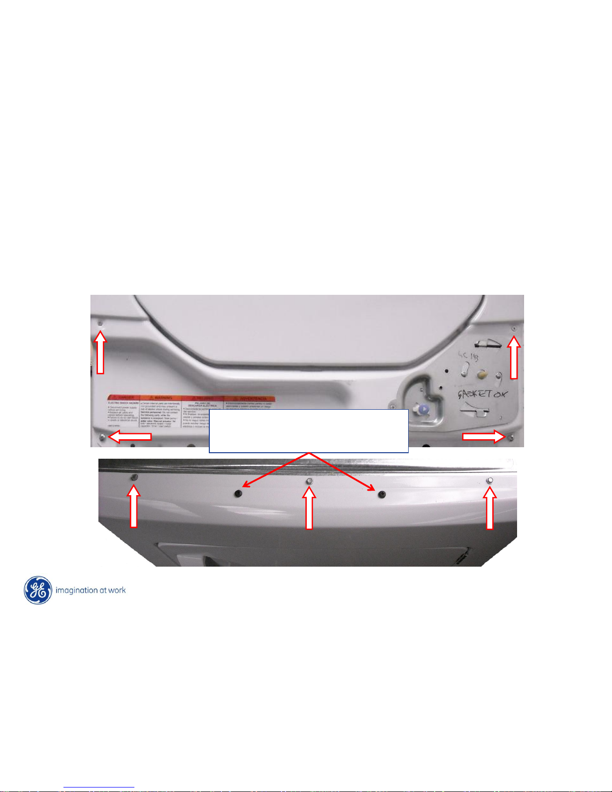
24” Control Panel Access
To access the washer/dryer controls; remove five Phillips screws, one on each side of
the control panel and three on the front opening. Remove the dryer control knob and tilt
the panel forward.
Copyright General Electric 2010
27” Control Panel Access
To access the washer/dryer controls; remove six Phillips screws, two on each side of the
control panel and two on the front bottom door opening. Remove the dryer control knob
and tilt the panel forward.
Copyright General Electric 2010
Control Panel
Washer Controls
Dryer Timer &
Start Switch
To remove the control panel from the cabinet; slide the panel to the right to release the
locking tabs from the slots. The washer controls are installed on the control panel, dryer
timer and start switch remain on the dryer front panel.
Copyright General Electric 2010
Control Panel
To replace any of the washer controls; remove the selection knob from the front, lift the
locking lever and rotate the control to the left to release from the control panel.
Copyright General Electric 2010
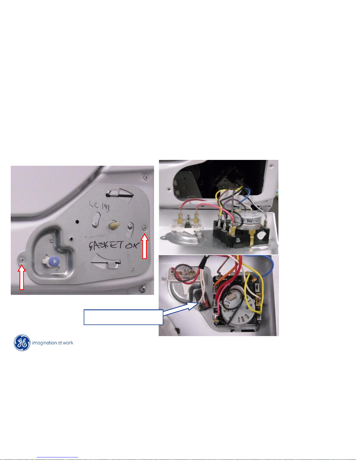
Control Panel
To replace the dryer timer or start switch (Timer motor dropping resistor EL); remove two
Phillips screws from the control bracket and remove the bracket from the front panel.
Both the dryer timer and start switch are twist lock connected to the control bracket.
Gas Model
Electric Model
Dropping Resistor
Copyright General Electric 2010
Control Panel
The timer dropping resistor (on electric models) controls the run time during automatic
cycles. This 4500 ohm resistor is in series with the timer motor, when the thermostat
trips turning off the heat – the resistor drops the 240 vac heater circuit to 120 vac to run
the timer motor. The resistor is held in place on the bracket with a single Phillips screw.
Dropping Resistor
Copyright General Electric 2010
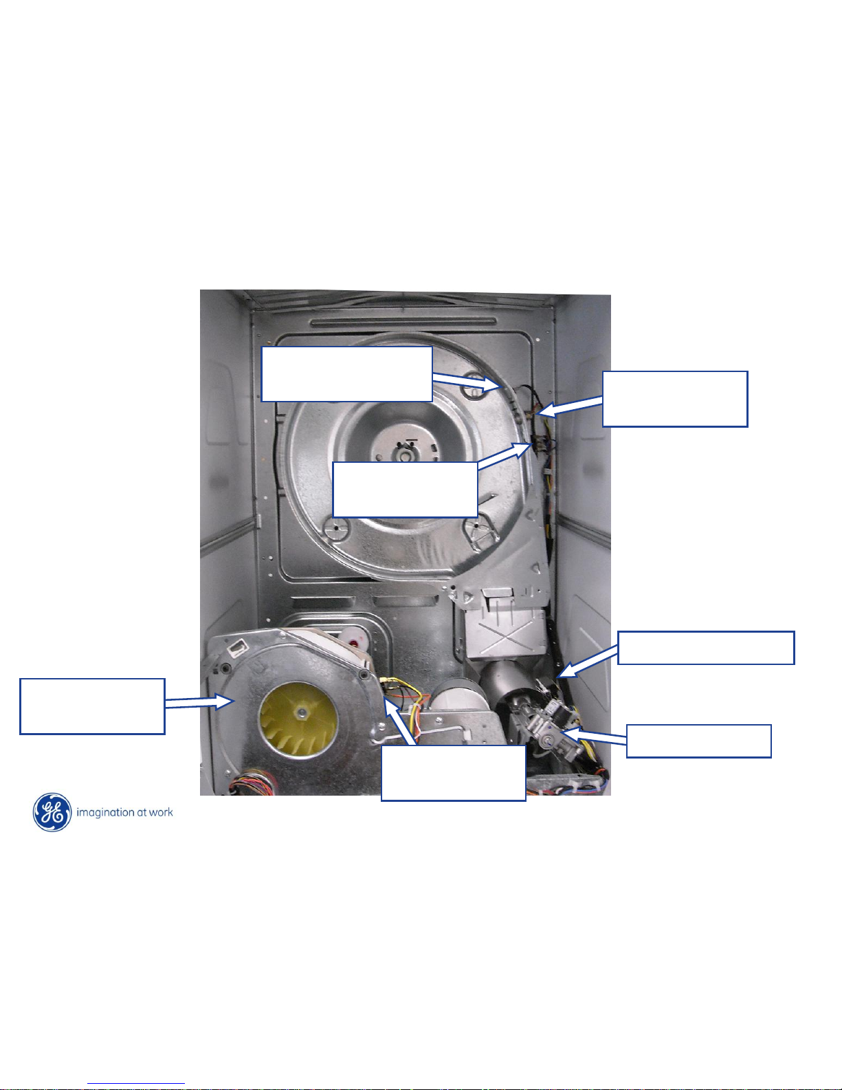
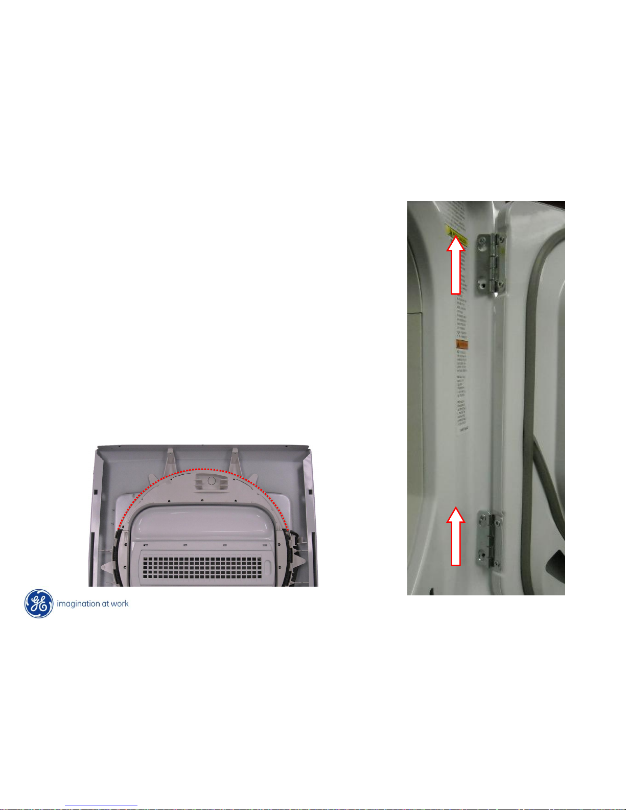
Dryer Front Panel Removal
To remove the dryer front panel; unplug the harness connectors behind the heat shield.
Remove the four Phillips screws from the front of the panel and three ¼” hex head
screws from the panel top. Pull out on the bottom of the panel and lift to release the
panel from the dryer drum.
Top Drum Bearing Screws
Do Not Remove
Copyright General Electric 2010
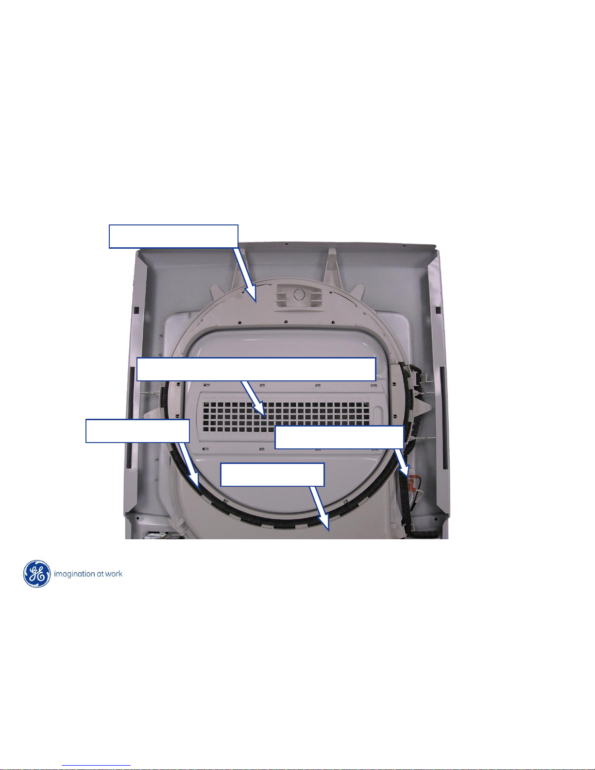
Lint Filter – not on 27” models
Door Switch
Drum Bearing
Drum Felt
24” Dryer Front Panel
Air Duct
Copyright General Electric 2010
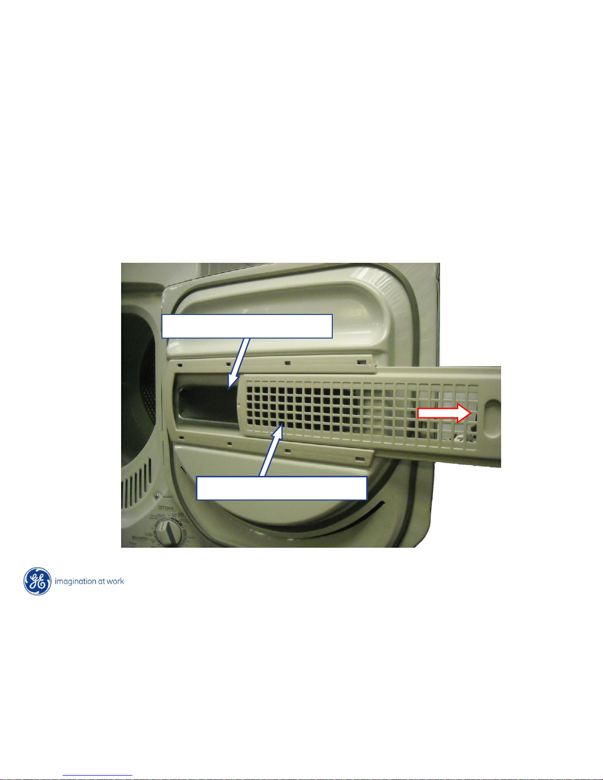
24” Dryer Front Panel
Screen Mesh Lint Filter
The lint filter is housed in the dryer door. To clean the lint filter, slide the cover from the
screen mesh filter and wipe off the lint from the mesh screen after each cycle.
Lint Filter Cover
Copyright General Electric 2010
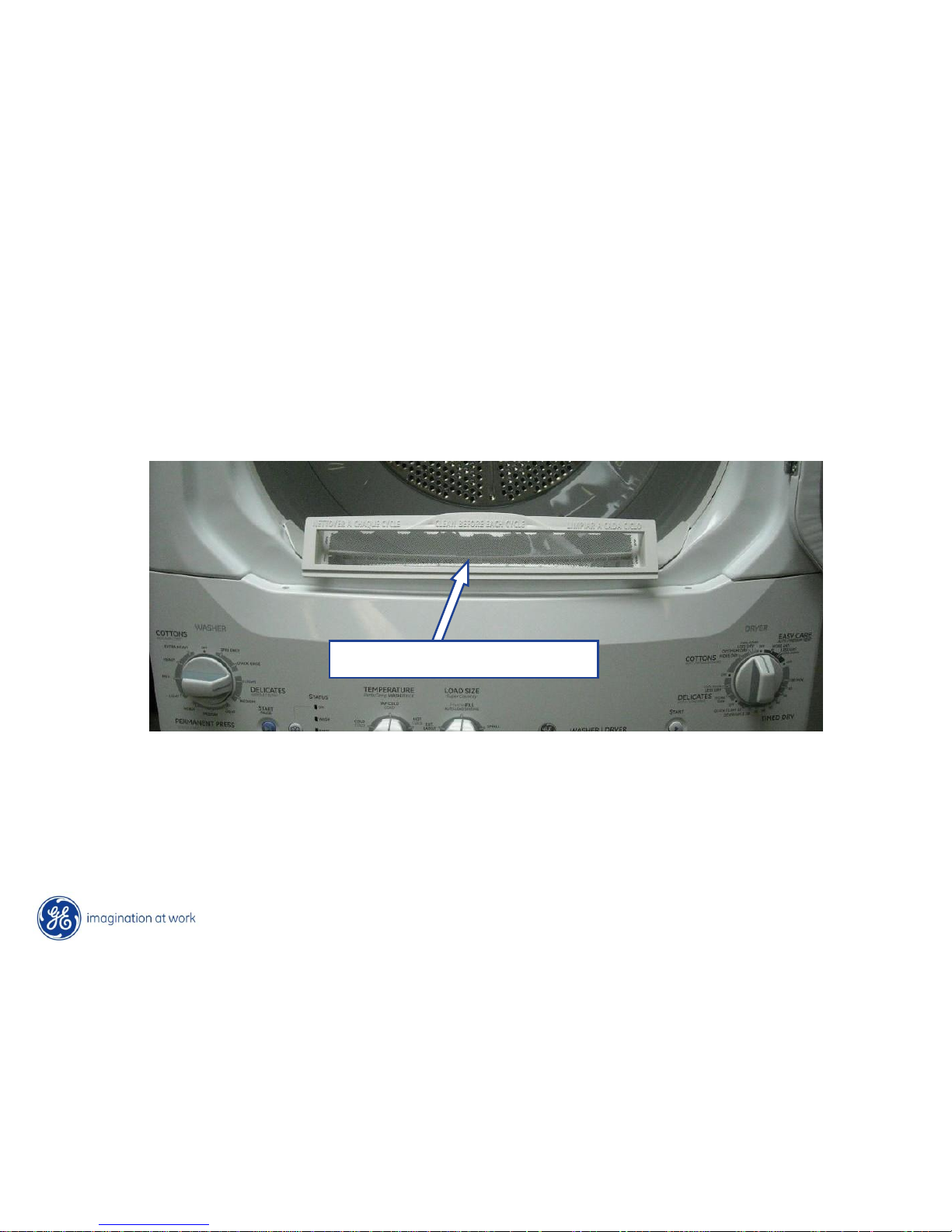
27” Dryer Front Panel
The lint filter is housed in the dryer front. To clean the lint filter, slide the filter up from the
front panel and wipe off the lint screen after each cycle.
Standard Lint Filter
Copyright General Electric 2010
Dryer Front Panel Installation
When removing or re-installing the dryer front panel;
remove the dryer door. Remove the bottom screw
from each hinge and loosen the second screw, lift the
door off of the dryer front.
Removing the dryer door allows for easier
manipulation of the dryer front as you place the dryer
front on the top of the cabinet and reach through the
door opening to push up on the dryer drum for
placement on the front top bearing.
Copyright General Electric 2010
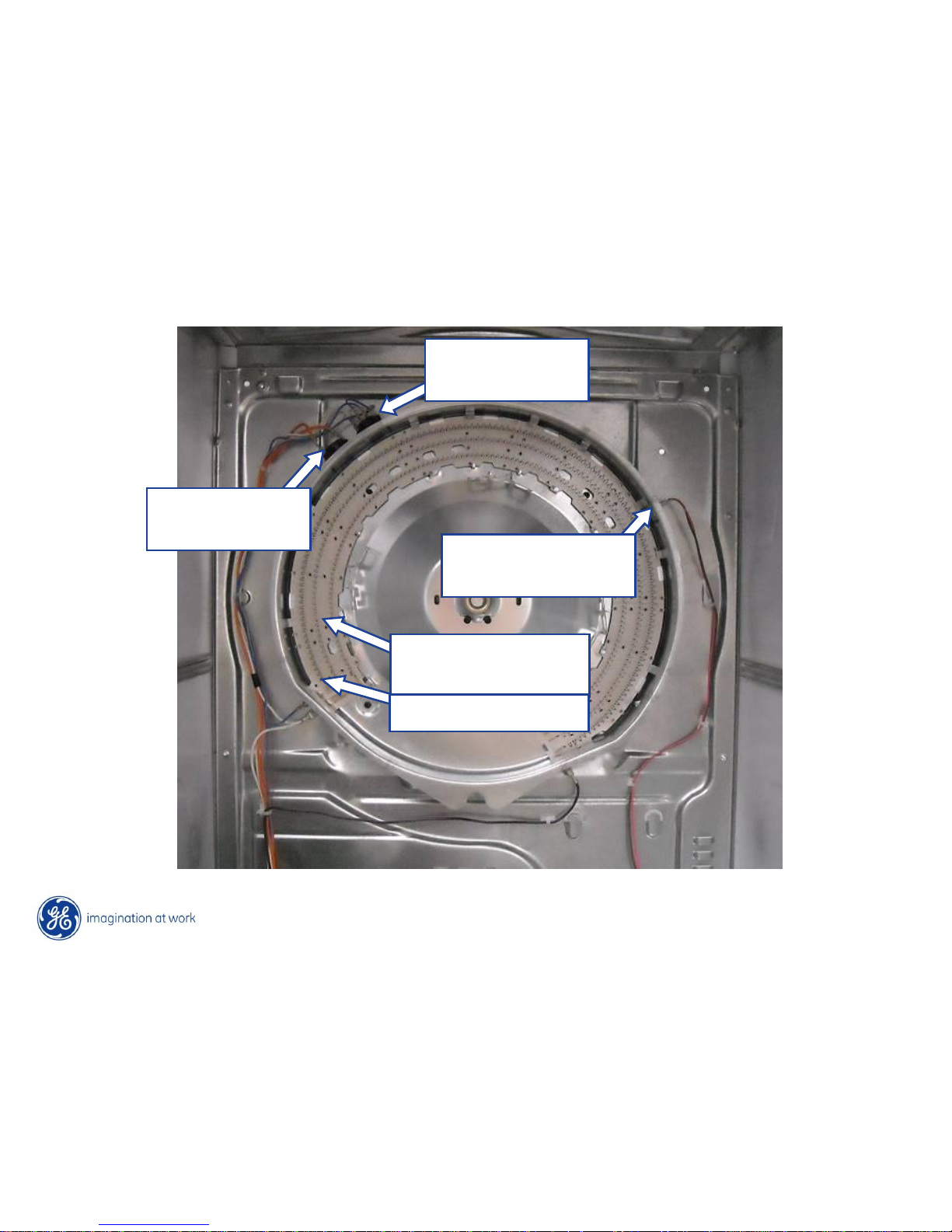
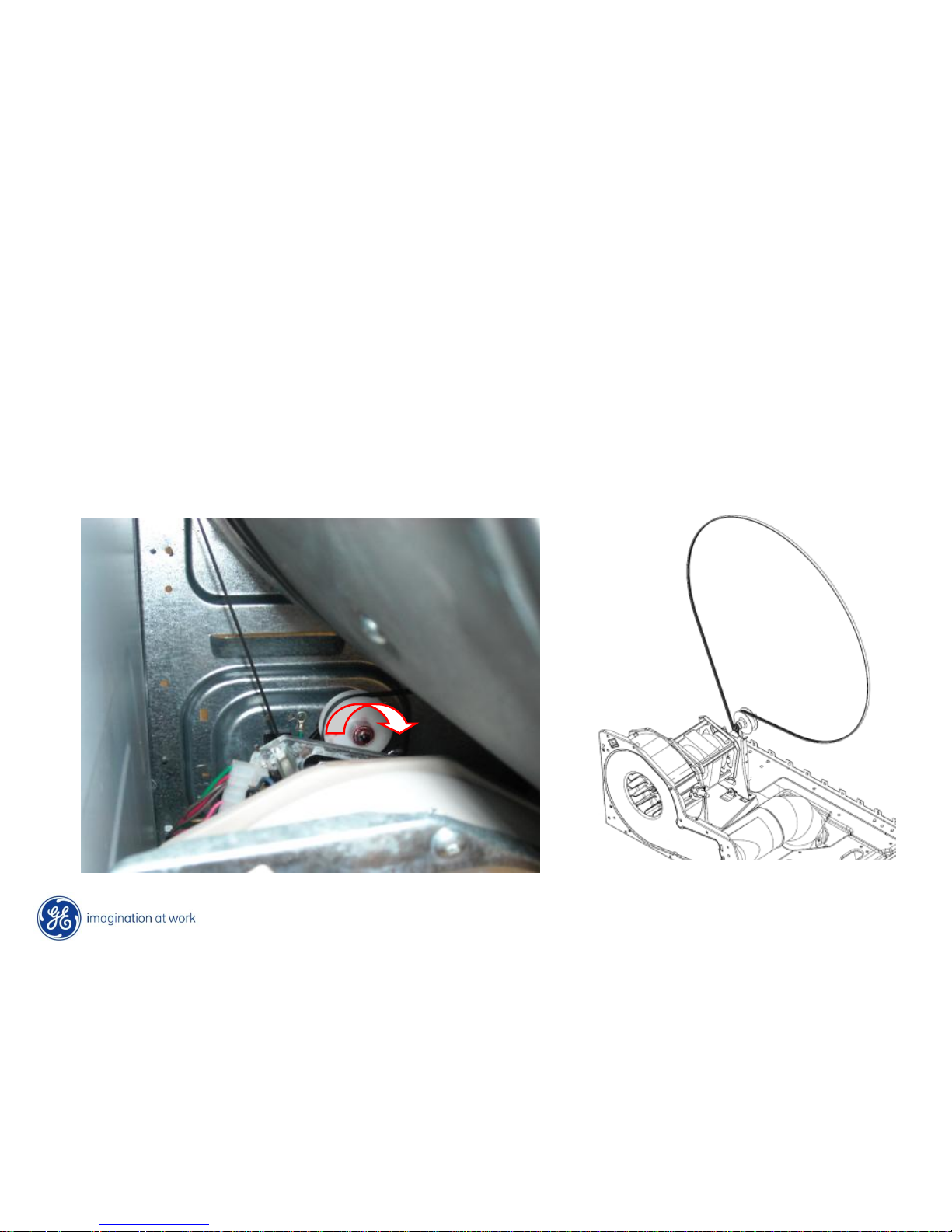
Dryer Drum Removal
To remove the dryer drum; lift up on the drum and push the idler pulley to the right
locking it onto the motor bracket, releasing tension on the belt for removal. The dryer
drum can then be removed from the dryer by pulling it forward. When re-installing the
dryer belt, position the belt on the drum and pulleys and unlock the idler to tension the
belt. Rotate the drum by hand CCW several times to ensure proper belt alignment.
Copyright General Electric 2010
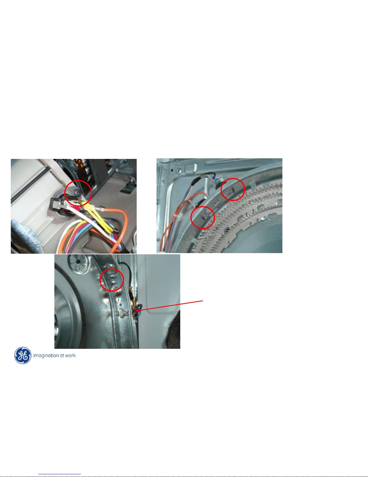
Dryer Thermostats
The dryer thermostats can be replaced by removing a single Phillips screw and
removing the stat from a locking tab.
The control inlet thermostat on
gas models utilize two locking
tabs instead of a Phillips screw.

Copyright General Electric 2010
Motor & Blower
The blower wheel is mounted to the motor shaft with an integral threaded nut. To
remove the blower wheel; lock the motor shaft and turn the blower nut CCW with a
15/16” (24mm) socket.
Copyright General Electric 2010
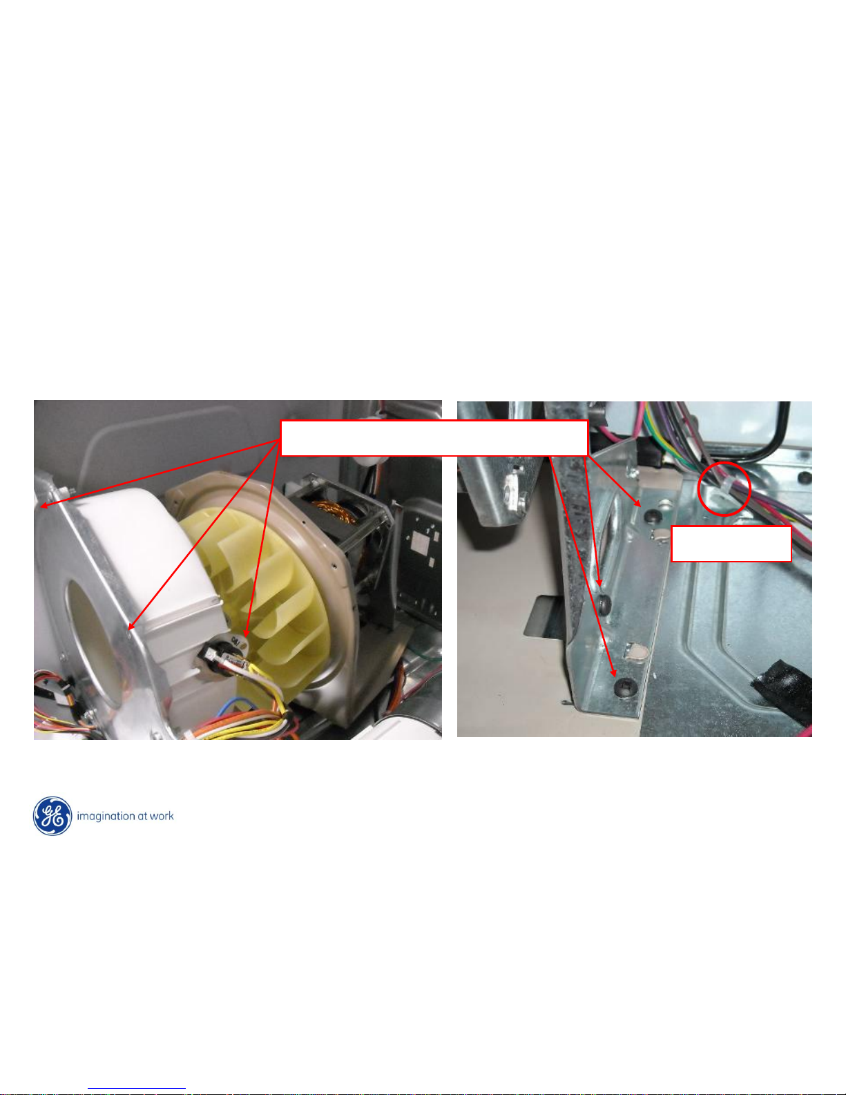
Motor & Blower
To remove the motor/blower assembly; remove three Phillips screws from the front
blower housing and the control thermostat. Remove three Phillips screws from the
rear motor bracket, disconnect the motor harness wire tie and move the assembly
to the rear of the dryer.
Six Phillips Screws
Wire Tie
Copyright General Electric 2010
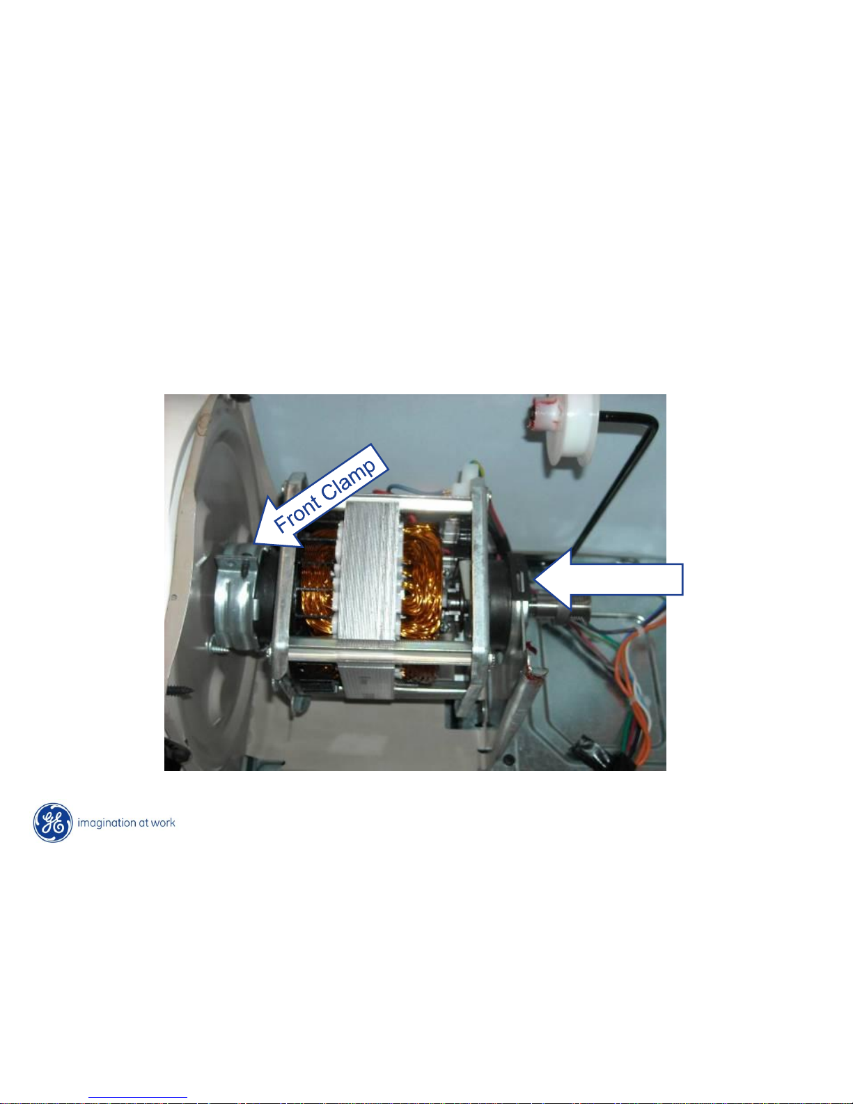
Motor & Blower
To replace the drive motor; you can pull the assembly as previously mentioned or,
loosen the front motor clamp and compress the rear clamp to unsnap it from the
rear motor bracket. Remember to unscrew the blower wheel.
Rear Clamp
 Loading...