

Page 1
PRINTED : Mar’2009 REF NO. SM7709033-00_11
Page : 1
SERVICE MANUAL Refrigerator FOR EXPORT 2009
1 Specifications
1-1) Specific parts for specific countries
Item
No.
Model Destination
Power Source
(Voltage-ac / Hz)
Power Cord
Internal Volume (Litre)
(by ISO 8561;1995)
1. GTU150PAXR AUSTRALIA (AU) 240 / 50 O3 Australia plug 440
Page 2
PRINTED : Mar’2009 REF NO. SM7709033-00_11
Page : 2
1-2) Product
Model GTU150PAXR
Classification 2 Doors No Frost
Temperature Control Thermostat Electronic
Defrost System Automatic
Drain Automatic (Heat by transfer from the Condenser)
Evaporator Aluminum Coil With Bond
Condenser Copper Tube Inside
Cabinet Rigid Polyurethane Foam (Cyclopentane)
Freezer Door Rigid Polyurethane Foam (Cyclopentane)
Insulation
Refrigerator Door Rigid Polyurethane Foam (Cyclopentane)
Refrigerant HFC-134a
Refrigerant Charge (g.) 150
Overall Dimension (WxDxH (mm.)) 727 x 711 x 1715
Packing Dimension (WxDxH (mm.)) 773 x 790 x 1813
Net Weight (kg.) 80.0
Gross Weight (kg.) 88.0
1-3) Characteristic of Thermostat
Operating Temperature (°C) 1013hPa (mb)
Model MM1-8053
Dial Position ON OFF
WARM
°C
-18.4 -21.7
NORMAL
°C -21 ± 1.5 -24.5 ± 1.5
Temperature
Control
COLD
°C
-26.7 -30.9
1-4) Electrical Parts
1-4-1) MODEL GTU150PAXR
Model C-BF175L5Z
Compressor
Power Supply Range
220-240 V / 50 Hz
Starting Relay PTH7M330MD2
Overload Protector 4TM276RHBYY-53
Starting Capacitor -
Running Capacitor
4.0µF / 400 VAC
Interior Light 240 V / 10 W
Page 3
PRINTED : Mar’2009 REF NO. SM7709033-00_11
Page : 3
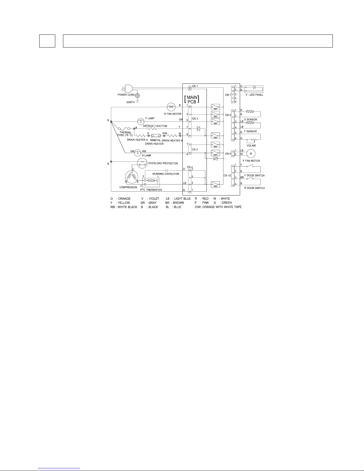
2 Wiring Diagram
Model : GTU150PAXR
Page 4
PRINTED : Mar’2009 REF NO. SM7709033-00_11
Page : 4
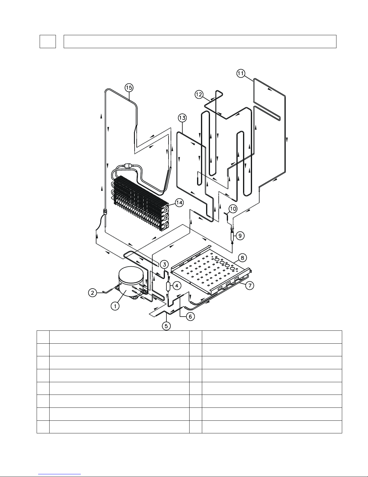
3 Refrigerant Circuit
Model : GTU150PAXR
1 COMPRESSOR 9 DRYER ASS’Y
2 TUBE CHARGE 10 TUBE DISCHARGE
3 TUBE CONNECT 139 11 TUBE FRAME
4 ACCUMULATOR / MUFFER 12 TUBE CREST
5 TUBE CONNECT 145 13 TUBE CREST S
6 TUBE CONNECT 143 14 EVAPORATOR ASS’Y
7 CONDENSER PIPE 15 SUCTION TUBE ASS’Y
8 CONDENSER PLATE
Page 5
PRINTED : Mar’2009 REF NO. SM7709033-00_11
Page : 5
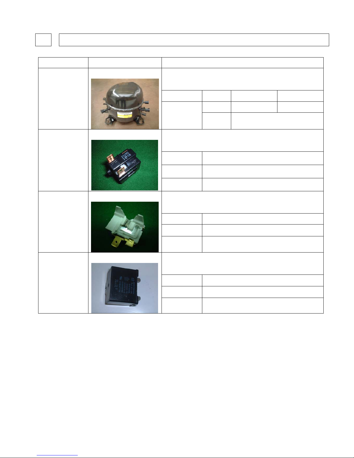
4 Trouble Shooting
4-1) MODEL GTU150PAXR
Part Name Picture Check Method and Criterion
Measure the resistance with a tester.
(Ambient temperature : Room temperature 25°C)
Model Main Wiring Auxiliary Wiring
Normal
11.60 Ω (Approx.) 17.34 Ω (Approx.)
Compressor
C-BF175 L5Z
Abnormal
Open(∞ Ω) or Short Circuited (0 Ω)
Measure the resistance with a tester.
(Ambient temperature : Room temperature 25°C)
Model PTH7M330MD2
Normal
33 Ω ± 20% (Approx.)
Starting Relay
Abnormal
Open(∞Ω) or Short Circuited (0Ω)
Measure the resistance with a tester.
(Ambient temperature : Room temperature 25°C)
Model 4TM276RHBYY-53
Normal
Less than 1 Ω (Approx.)
Overload Protector
Abnormal
Open(∞Ω) or Short Circuited (0Ω)
Measure the resistance with a tester.
(Ambient temperature : Room temperature 25°C)
Model
4.0 µF / 400 VAC
Normal
Open(∞Ω)
Running Capacitor
Abnormal
Short Circuited (0Ω)
Page 6
PRINTED : Mar’2009 REF NO. SM7709033-00_11
Page : 6
5 Replacement of Parts
• Unplug the power cord before servicing.
1. Model : GTU150PAXR
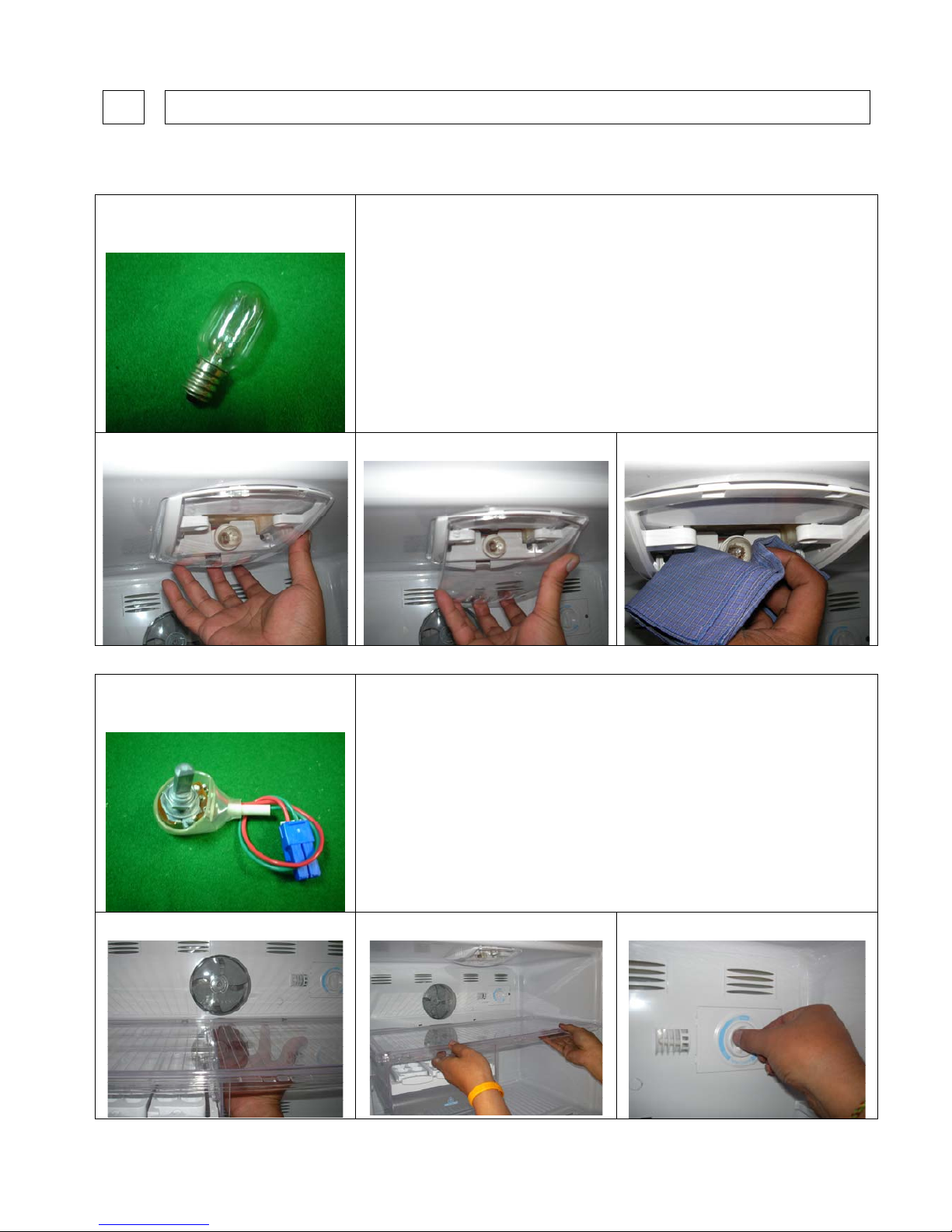
Part Name
Lamp
Operating Procedure
1. Release Freezer Shield Light lock. 2. Remove Freezer Shield Light. 3. Turn Lamp counterclockwise to remove.
4. After replacing Lamp, reverse the steps above.
Part Name
Volume Ass’y
Operating Procedure
* Freezer Corner reassembling.
1. Release Freezer Corner lock. 2. Remove Freezer Corner. 3.Turn Knob Thermo F to “Min” position.
Page 7
PRINTED : Mar’2009 REF NO. SM7709033-00_11
Page : 7
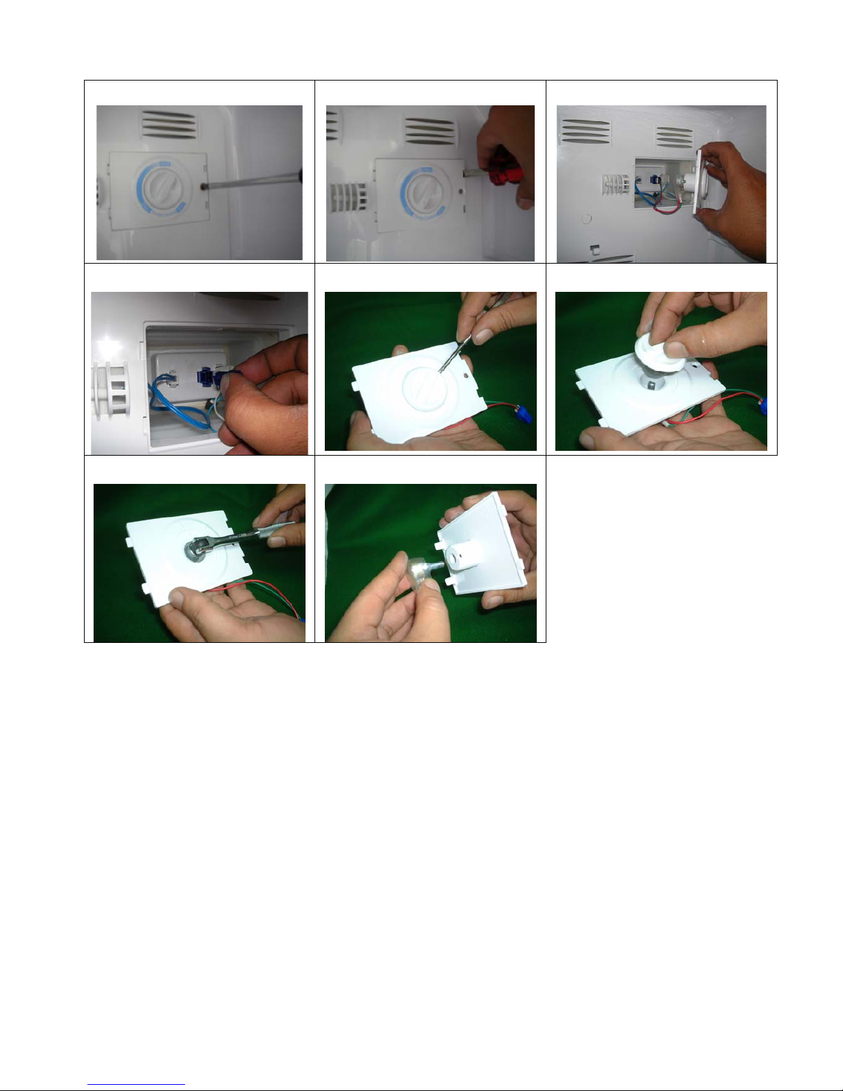
4. Release screw form Cover. 5. Dig Cover out. 6. Pull out Cover from FF.Cover.
7. Pull out Socket of Volume Ass’y.
8. Dig Knob Thermo F out. 9. Pull out Knob Thermo F from Cover.
10. Release Nut from Volume Ass’y.
11. Remove Volume Ass’y .
12. After replacing Volume Ass’y,
reverse the steps above.
Page 8
PRINTED : Mar’2009 REF NO. SM7709033-00_11
Page : 8
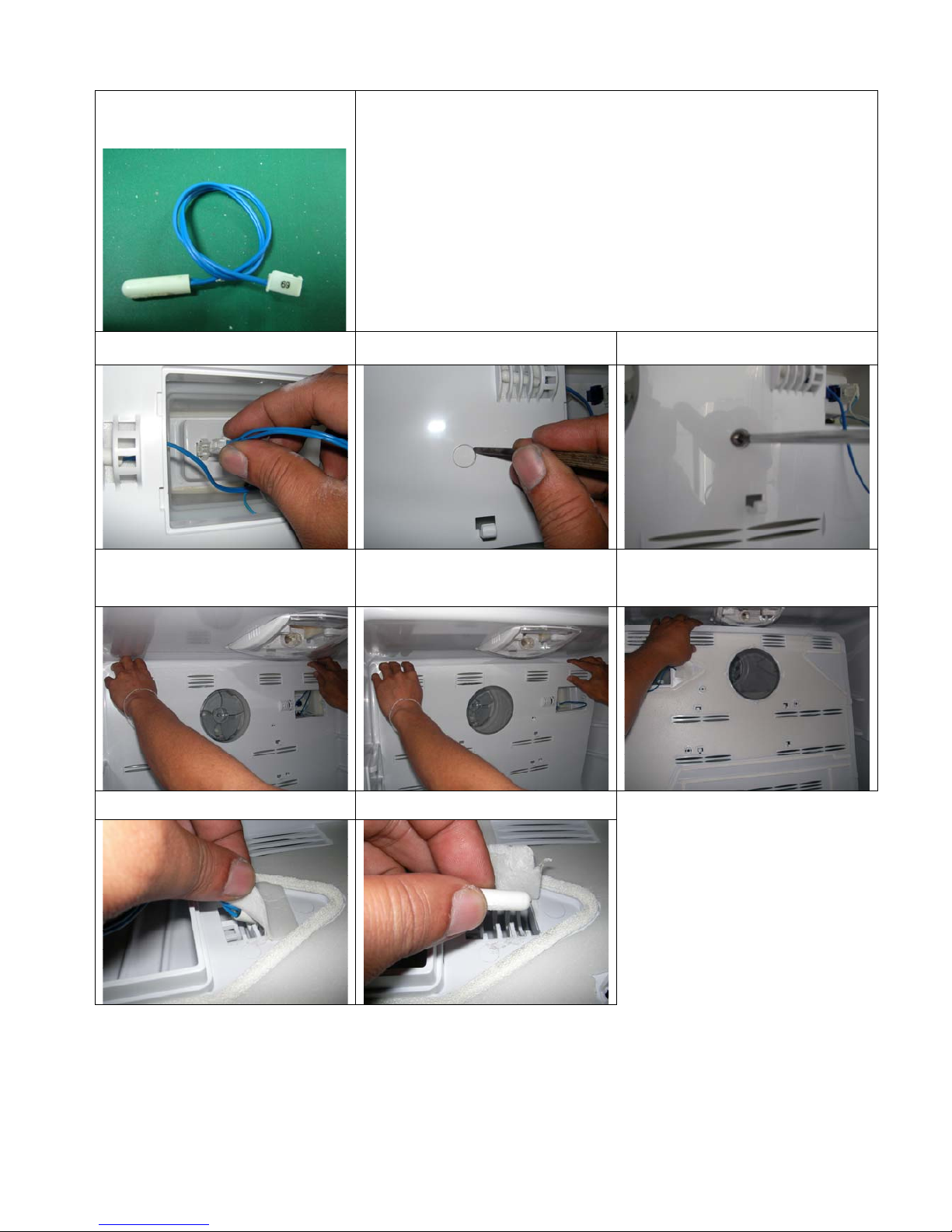
Part Name
Sensor Ass’y
Operating Procedure
- Follow step 1-7 of replacing Volume Ass’y.
1. Pull out Socket of Sensor Ass’y.
2. Dig Cover Cap out. 3. Release screw form FF.Cover.
4. Press FF.Cover to remove lock. 5. Lift FF.Cover out. 6. Return the FF.Cover to show behind
side.
7. Remove Seal from FF.Cover. 8. Pull out Sensor Ass’y from FF.Cover.
9. After replacing Sensor Ass’y, reverse
the steps above.
Page 9

PRINTED : Mar’2009 REF NO. SM7709033-00_11
Page : 9
Part Name
Fan Blade F.
Operating Procedure
- Follow step 1-7 of replacing Volume Ass’y.
- Follow step 1-5 of replacing Sensor Ass’y.
1. Use Pliers to catch at Fan Ring. 2. Pull out Fan Blade F from Plate MTG
Motor.
3. Pull out Fan Ring from Fan Blade F.
4. After replacing Fan Blade F, reverse the steps above.
Page 10

PRINTED : Mar’2009 REF NO. SM7709033-00_11
Page : 10
Part Name
Fan Motor F.
Operating Procedure
- Follow step 1-7 replacing Volume Ass’y.
- Follow step 1-5 replacing Sensor Ass’y.
- Follow step 1-3 replacing Fan Blade F.
1. Release screw form Plate MTG.
Motor.
2. Press Plate MTG. Motor to remove
lock.
3. Lift Plate MTG. Motor out.
4. Release screw form Cover Fan Motor. 5. Pull out Cover Fan Motor form Plate
MTG. Motor.
6. Lift Fan Motor F out.
7. Pull out Socket .
8. After replacing Fan Motor F, reverse the steps above.
Page 11

PRINTED : Mar’2009 REF NO. SM7709033-00_11
Page : 11
Part Name
Heater
Operating Procedure
- Follow step 1-7 replacing Volume Ass’y.
- Follow step 1-5 replacing Sensor Ass’y.
- Follow step 1-3 replacing Fan Blade F.
- Follow step 1-3 replacing Fan Motor F.
1. Pull out Socket of Heater. 2. Pull out Socket of Heater.
3.
Hold firmly and life Evaporator Ass’y up.
4. Remove Aluminium tape that cover
electrical wire.
5. Lift up Heater set form its lock.
6. After replacing Heater, reverse the
steps above.
Page 12

PRINTED : Mar’2009 REF NO. SM7709033-00_11
Page : 12
Part Name
Thermal Fuse Ass’y
Operating Procedure
- Follow step 1-7 replacing Volume Ass’y.
- Follow step 1-5 replacing Sensor Ass’y.
- Follow step 1-3 replacing Fan Motor F.
- Follow step 3 replacing Heater.
1. Pull out Socket of Thermal Fuse
Ass’y.
2. Cut out Cable Tie from Evaporator
tube.
3. Cut out Cable Tie from Evaporator
tube.
4. Remove Thermal Fuse Ass’y.
5. After replacing Thermal Fuse Ass’y, reverse the steps above.
Page 13

PRINTED : Mar’2009 REF NO. SM7709033-00_11
Page : 13
Part Name
D Sensor Ass’y
Operating Procedure
- Follow step 1-7 replacing Volume Ass’y.
- Follow step 1-5 replacing Sensor Ass’y.
- Follow step 1-3 replacing Fan Motor F.
- Follow step 3 replacing Heater.
1. Pull out Socket of D Sensor Ass’y. 2. Cut out Cable Tie from Evaporator
tube.
3. Remove Aluminium tape that cover D
Sensor Ass’y.
1. After replacing D Sensor Ass’y, reverse the steps above.
Part Name
Door Switch.
Operating Procedure
* Use a small flatten screwdriver to prize Door Switch.
1. Dig Door Switch out. 2. Pull Door Switch form Inner Box. 3. Hold recept Socket.
4. After replacing Door Switch, reverse the steps above.
Page 14

PRINTED : Mar’2009 REF NO. SM7709033-00_11
Page : 14
Part Name
Lamp.
Operating Procedure
1. Pull out Tray Chiller. 2. Unlock Shield Light R out. 3. Remove Shield Light R from Duct.
4. Turn Lamp counterclockwise to
remove.
5. Remove Lamp from Lamp socket.
6. After Replacing Lamp, Reverse steps
above.
Page 15

PRINTED : Mar’2009 REF NO. SM7709033-00_11
Page : 15
Part Name
Fan Blade R
Operating Procedure
1. Remove Tray Chiller. 2. Release Door. 3. Remove Tray Chiller.
4. Unlock Fan Cover out. 5. Remove R Fan Cover from Cover
Thermo.
6. Dig Fan Ring.
4. Pull Fan Blade R from Cover Thermo. 5. After Replacing Fan Blade R, Reverse steps above.
Page 16

PRINTED : Mar’2009 REF NO. SM7709033-00_11
Page : 16
Part Name
Damper Thermostat
Operating Procedure
1. Remove Tray Chiller. 2. Release Door. 3. Remove Tray Chiller.
4. Dig Cover Cap out. 5. Release screw from Cover Thermo. 6. Dig Knob Thermo R.
7. Pull out Knob Thermo R from Cover
Thermo.
8. Lift out Cover Thermo. 9. Lift out Insulation.
Page 17

PRINTED : Mar’2009 REF NO. SM7709033-00_11
Page : 17
10. Remove paper tape from Insulation. 11. Remove Seal from Insulation. 12. Remove paper tape from Damper
Thermostat.
13. Straighten Damper Thermostat
sensing tube.
14. Separate Insulation from each other. 15. Pull Case Damper from Insulation.
16. Release screws that hold Damper
Thermostat and Case Damper.
17. Pull Damper Thermostat from Case
Damper.
18. After Replacing Damper Thermostat,
Reverse steps above.
Page 18

PRINTED : Mar’2009 REF NO. SM7709033-00_11
Page : 18
Part Name
UV-PCB.
Operating Procedure
- Follow stop 1-9 of replacing Damper Thermostat.
1. Release screws form Duct. 2. Lift out Duct and Insulation L-R. 3. Release screws form Plate MTG.
4. Lift out Plate MTG. 5. Pull out Socket. 6. Release screws form Plate MTG.
7. Lift out Plate MTG. 8. Press UV-PCB to remove lock. 9. Lift out UV-PCB.
10. After replacing UV-PCB, reverse the steps above.
Page 19

PRINTED : Mar’2009 REF NO. SM7709033-00_11
Page : 19
Part Name
Lamp Socket.
Operating Procedure
- Follow stop 1-9 of replacing Damper Thermostat.
- Follow stop 1-5 of replacing UV-PCB.
1. Remove paper tape form Plate MTG
008.
2. Press R Lamp Socket to remove lock. 3. Lift out R Lamp Socket.
2. After replacing R Lamp Socket, reverse the steps above.
Page 20

PRINTED : Mar’2009 REF NO. SM7709033-00_11
Page : 20
Part Name
Fan Motor R.
Operating Procedure
- Follow stop 1-9 of replacing Damper Thermostat.
- Follow stop 1-5 of replacing UV-PCB.
1. Release screws form PLT MTG Fan
Motor.
2. Lift out PLT MTG Fan Motor. 3. Lift out Fan Motor R.
4. Pull out Terminal.
5. After replacing Fan Motor R, reverse the steps above.
Page 21

PRINTED : Mar’2009 REF NO. SM7709033-00_11
Page : 21
Part Name
Running Capacitor.
Operating Procedure
* Open Cover Case Elec. Must be release screw ( 1 piece ) then remove the lock
between Case Elec. and Cover Case Elec.
1. Release screw form Case Elec. 2. Lift out Case Elec. 3. Pull out Case Elec. Form Cover Case
Elec.
4. Release screw form Running
Capacitor.
5. Pull out Terminal form Running
Capacitor.
6. After Replacing Running Capacitor,
Reverse steps above.
Page 22

PRINTED : Mar’2009 REF NO. SM7709033-00_11
Page : 22
Part Name
Main PCB.
Operating Procedure
- Follow stop 1-5 of replacing Running Capacitor.
1. Press Main PCB to remove lock. 2. Lift out Main PCB. 3. Pull out Socket Main PCB.
4. After Replacing Main PCB, Reverse steps above.
Page 23

PRINTED : Mar’2009 REF NO. SM7709033-00_11
Page : 23
Part Name
Starting Relay.
Operating Procedure
- Follow stop 1-2 of replacing Running Capacitor.
1. Release Relay Cover Fixing Clip. 2. Remove Relay Cover. 3. Remove Starting Relay.
4. Hold Recept Terminal then pull
electical wires from Starting Relay.
5. After Replacing Starting Relay, Reverse steps above.
Page 24

PRINTED : Mar’2009 REF NO. SM7709033-00_11
Page : 24
Part Name
Overload Protector
Operating Procedure
- Follow stop 1-2 of replacing Running Capacitor.
- Follow stop 1-3 of replacing Starting Relay.
1. Remove Overload Protector. 2. Pull off Overload Protector. 3. Hold Recept Terminal then pull
electical wires from Overload Protector.
4. After Replacing Overload Protector, Reverse steps above.
 Loading...