

Page 1
www.GEAppliances.ca
Safety Instructions 2-5
Installation Instructions 6-20
Electric Dryer
Gas Dryer
Reversing the Door
Operating Instructions 21-25
Control Panel
Control Settings
Dryer Features
Loading and Using the Dryer 25
Troubleshooting Tips 26 , 27
Consumer Support 29, 30
Consumer Support
Warranty
Dryers
• • • • • • • • • • • • • •
• • • • • • • • • • • • • • • • •
• • • • • • •
• • • • • • • • • • • • • • •
• • • • • • • • • • • • •
• • • • • • • • • • • • • •
• • • • • • • • • •
• • • • • • • • • • • • • • • • • • •
6-12
13-19
20
21, 22
23
24
30
29
Use and Care
With Installation Instructions.
Note to Consumer:
This product was veried to be
in excellent condition when it left
our manufacturing facility. If it
has been damaged during transit
or installation, please report that
damage immediately to the Retail
Outlet where it was purchased.
Although your warranty covers
manufacturing defects in material
or workmanship, it does not
include coverage for delivery
damage. Please refer to your
warranty section for specic
information about warranty terms
and conditions.
Write the model and serial
numbers here:
Model#
Serial #
They are on the label on the
front of the dryer behind the
door.
500A292P014 Rev.0
Page 2

IMPORTANT SAFETY INFORMATION
READ ALL INSTRUCTIONS BEFORE USING
WARNING!
For your safety, the information in this manual must be followed to minimize the risk
of re or explosion, electric shock, or to prevent property damage, personal injury, or
Safety Instructions
death.
Do not store or use gasoline or other
ammable vapors and liquids in the
vicinity of this or any other appliance.
Installation and service must be
performed by a qualied installer,
service agency or the gas supplier.
WHAT TO DO IF YOU SMELL GAS:
Do not try to light a match, or cigarette,
1
or turn on any gas or electrical
appliance.
Do not touch any electrical switch; do
2
not use any phone in your building.
Clear the room, building or area of all
3
occupants.
Immediately call your gas supplier
4
from a neighbor’s phone. Follow the
gas supplier’s instructions carefully.
If you cannot reach your gas supplier,
5
call the re department.
Operating Instructions Installation InstructionsTroubleshooting Tips
Consumer Support
2
Page 3

www.GEAppliances.ca
PROPER INSTALLATION
This dryer must be properly installed and located in accordance with the Installation Instructions before
it is used, present in this manual.
Safety Instructions
Properly ground dryer to conform to all governing
codes and ordinances. Follow details in
Installation Instructions section.
Install or store where it will not be exposed to
temperatures below freezing or exposed to the
weather.
Connect to a properly rated, protected and sized
power supply circuit to avoid electrical overload.
Remove the protective lm from both the control
panel and the door.
Remove all sharp packing items and dispose of all
shipping materials properly.
Do not remove the vent protector from the back
of the dryer. Pull the protector out and down to its
lowest position and connect the exhaust duct to
the dryer. The lowered protector will prevent the
duct from getting crushed.
Exhaust/Ducting:
Dryers MUST be exhausted to the outside to
1
prevent large amounts of moisture and lint from
being blown into the room.
Use only rigid metal or exible metal 10 cm (4”)
2
diameter ductwork inside for exhausting to the
outside.
USE OF PLASTIC OR OTHER COMBUSTIBLE
DUCTWORK CAN CAUSE A FIRE. PUNCTURED
DUCTWORK CAN CAUSE A FIRE IF IT COLLAPSES
OR BECOMES OTHERWISE RESTRICTED IN USE
OR DURING INSTALLATION.
For complete details, follow the Installation
Instructions.
Installation Instructions
Operating Instructions
Troubleshooting Tips
Consumer Support
3
Page 4

IMPORTANT SAFETY INFORMATION
READ ALL INSTRUCTIONS BEFORE USING
WARNING!
YOUR LAUNDRY AREA
Keep the area underneath and around your
Safety Instructions
appliances free of combustible materials (lint,
paper, rags, etc), gasoline, chemicals, and other
ammable vapors and liquids.
Keep the oor around your appliances clean and
dry to reduce the possibility of slipping.
Close supervision is necessary if this appliance is
used near children. Do not allow children to play
on, with or inside this or any other appliance.
WHEN USING YOUR DRYER
Never reach into the dryer while the drum is
moving. Before loading, unloading or adding
clothes, wait until the drum has completely
stopped.
Clean the lint lter before each load to prevent
lint accumulation inside the dryer or in the room.
DO NOT OPERATE THE DRYER WITHOUT THE LINT
FILTER IN PLACE.
Do not wash or dry articles that have been
cleaned in, washed in, soaked in or spotted with
combustible or explosive substances (such as
wax, oil, paint, gasoline, degreasers, dry-cleaning
solvents, kerosene, etc.) which may ignite or
Operating Instructions Installation InstructionsTroubleshooting Tips
explode. Do not add these substances to the
wash water. Do not use or place these substances
around your washer or dryer during operation.
Do not place items exposed to cooking oils in your
dryer. Items contaminated with cooking oils may
contribute to a chemical reaction that could cause
a clothes load to catch re.
Any article on which you have used a cleaning
solvent or that contains ammable materials (such
as cleaning cloths, mops, towels used in beauty
salons, restaurants or barber shops, etc.) must not
be placed in or near the dryer. There are many
highly ammable items used in homes such as
acetone, denatured alcohol, gasoline, kerosene,
some household cleaners, some spot removers,
turpentines, waxes, wax removers and products
containing petroleum distillates.
Keep all laundry aids (such as detergents,
bleaches, etc.) out of the reach of children,
preferably in a locked cabinet. Observe all
warnings on container labels to avoid injury.
Never climb on or stand on the dryer top.
The laundry process can reduce the ame
retardancy of fabrics. To avoid such a result,
carefully follow the garment manufacturer’s care
instructions.
Do not dry articles containing rubber, plastic,
foam or similar materials such as padded bras,
tennis shoes, galoshes, bath mats, rugs, bibs, baby
pants, plastic bags, pillows, etc., that may melt
or burn. Some rubber materials, when heated,
can under certain circumstances produce re by
spontaneous combustion.
Do not store plastic, paper or clothing that may
burn or melt on top of the dryer during operation.
Garments labeled Dry Away from Heat or Do not
Tumble Dry (such as life jackets containing kapok)
must not be put in your dryer.
Do not dry berglass articles in your dryer. Skin
irritation could result from the remaining particles
that may be picked up by clothing during
subsequent dryer uses.
To minimize the possibility of electric shock,
unplug this appliance from the power supply or
disconnect the dryer at the building’s distribution
panel by removing the fuse or switching off
the circuit breaker before attempting any
maintenance or cleaning (except the removal
and cleaning of the lint lter). NOTE: Pressing
START, PAUSE or POWER does NOT disconnect the
appliance from the power supply.
Consumer Support
4
Page 5

WHEN USING YOUR DRYER (cont.)
Safety Instructions
www.GEAppliances.ca
Never attempt to operate this appliance if it is
damaged, malfunctioning, partially disassembled,
or has missing or broken parts, including a
damaged cord or plug.
The interior of the machine and the exhaust duct
connection inside the dryer should be cleaned at
least once a year by a qualied technician. See the
Loading and Using the Dryer section.
If yours is a gas dryer, it is equipped with an
automatic electric ignition and does not have a
pilot light. DO NOT ATTEMPT TO LIGHT WITH A
MATCH. Burns may result from having your hand
in the vicinity of the burner when the automatic
ignition turns on.
WHEN NOT USING YOUR DRYER
Grasp the plug rmly when disconnecting this
appliance to avoid damage to the cord while
pulling. Place the cord away from trafc areas so
it will not be stepped on, tripped over or subjected
to damage.
You may wish to soften your laundered fabrics
or reduce the static electricity in them by using
a dryer-applied fabric softener or an anti-static
conditioner. We recommend you use either a
fabric softener in the wash cycle, according
to the manufacturer’s instructions for those
products, or try a dryer-added product for which
the manufacturer gives written assurance on
the package that their product can be safely
used in your dryer. Service or performance
problems caused by use of these products are
the responsibility of the manufacturers of those
products and are not covered under the warranty
to this appliance.
Before discarding a dryer, or removing it from
service, remove the dryer door to prevent children
from hiding inside.
Do not tamper with controls.
Installation Instructions
Operating Instructions
Do not attempt to repair or replace any part of
this appliance or attempt any servicing unless
specically recommended in this Owner’s Manual
or in published user-repair instructions that you
understand and have the skills to carry out.
READ AND FOLLOW THIS SAFETY INFORMATION CAREFULLY.
SAVE THESE INSTRUCTIONS
Troubleshooting Tips
Consumer Support
5
Page 6
Electric Dryer
Safety Instructions
BEFORE YOU BEGIN:
Read these instructions completely and carefully.
IMPORTANT - Save these instructions for local
inspector’s use.
IMPORTANT - Observe all governing codes and
ordinances.
Note to Installer - Be sure to leave these instructions with the
customer.
Note to Customer - Keep these instructions with your Use
and Care Book for future reference.
Before the old dryer is removed from service or discarded,
remove the dryer door.
Service information and the wiring diagram are located in the
control console.
Install the dryer where the temperature is above 10° C (50°F)
for satisfactory operation of the dryer control system.
NOTE: Installation and service of this dryer requires basic mechanical and electrical skills. It is your responsibility to contact a
qualied installer to make the electrical connections.
WARNING!
FOR YOUR SAFETY:
Use only rigid metal or exible metal 4-in. diameter
ductwork for exhausting to the outdoors. Never use plastic
or other combustible, easy-to-puncture ductwork.
This appliance must be properly grounded and installed as
described in these instructions.
Do not install or store appliance in an area where it will be
exposed to water and/or weather.
This dryer must be exhausted to the outdoors.
Inspect the dryer exhaust outlet and straighten the outlet
walls if they are bent.
Do not allow children on or in the appliance. Close
supervision of children is necessary when the appliance is
used near children.
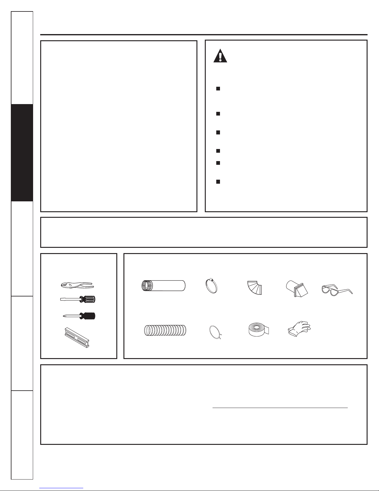
TOOLS YOU
WILL NEED
Operating Instructions Installation InstructionsTroubleshooting Tips
SLIP JOINT PLIERS
FLAT BLADE SCREWDRIVER
PHILLIPS SCREWDRIVER
LEVEL
Step 1 Prepare the area and exhaust for installation of
new dryer (see section 1).
Step 2 Check and ensure the existing external exhaust is
clean (see section 1) and meets attached
installation specications (see section 3).
Step 3 Remove the foam shipping pads (see section 1).
Step 4 Move the dryer to the desired location.
Step 5 Connect the power supply (see section 2).
Step 6 Connect the external exhaust (see section 4).
Step 7 Level your dryer (see section 5).
1O cm (4 in.) DIA.
METAL DUCT (RECOMMENDED)
1O cm (4 in.) DIA. FLEXIBLE METAL
DUCT (IF NEEDED)
MATERIALS YOU
WILL NEED
1O cm (4 in.) DUCT
CLAMPS (2)
OR
10 cm (4 in.) SPRING
CLAMPS (2)
Step 8 Check the operation of the power supply and
venting.
Step 9 Place the owners Use and Care in a location
where it will be noticed by the owner.
For alcove or closet installation, see section 6.
For bathroom or bedroom installation, see section 7.
For mobile or manufactured home see, section 8.
For side or bottom exhaust, see section 9.
1O cm (4 in.)
METAL ELBOW
DUCT TAPE
EXHAUST
HOOD
GLOVES
SAFETY GLASSES
Consumer Support
6
Page 7

Electric Dryer
www.GEAppliances.ca
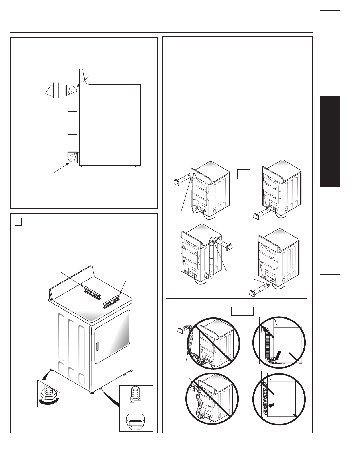
Minimum Clearance Other Than Alcove or Closet Installation
Minimum clearance to combustible surfaces and for air opening are: 0 cm (0 in.) clearance both sides and 2.5 cm (1 in.) rear.
Consideration must be given to provide adequate clearance for installation and service.
1 2
PREPARING FOR INSTALLATION
OF NEW DRYER
ELECTRICAL CONNECTION
INFORMATION
Safety Instructions
EXTERNAL
DUCT
OPENING
DUCT TAPE OR
DUCT CLAMP
10 cm (4 in.)
METAL DUCT
VENT
PROTECTION
BRACKET
TIP: Install your dryer before installing your washer.
This will allow better access when installing dryer exhaust.
DISCONTINUITY
ON DUCT
DUCT TAPE OR
DUCT CLAMP
Pull the vent protection bracket
out until it stops, and let it rest on
the oor. The bracket prevents
the unit from moving too close
to the wall and crushing the
rear vent. Prolong by adding a
DASHED FLEXIBLE duct.
REMOVING LINT FROM WALL EXHAUST
OPENING & FOAM REMOVAL FROM
DRYER LEGS
WALL
WARNING - TO REDUCE THE RISK
OF FIRE, ELECTRICAL SHOCK AND
PERSONAL INJURY:
DO NOT USE AN EXTENSION CORD OR AND
ADAPTER PLUG WITH THIS APPLIANCE.
Dryer must be electrically grounded in accordance
with local codes and ordinances. Installation must be
in accordance with the current CSA C22.1 Canadian
Electrical code part 1. Improper connection of the
equipment-grounding conductor can result in an electric
shock. Check with a qualied electrician or service
representative or personnel if you are in doubt as to
whether the appliance is properly grounded.
Do not modify the plug provided with the appliance: if it
will not t the outlet, have a proper outlet installed by a
qualied electrician.
ELECTRICAL REQUIREMENTS
This dryer must be connected to an individual branch
circuit, protected by the required time-delay fuses or
circuit breakers. The power supply must be of 120/240
volts, 60 Hz circuit with the wall receptacle as shown
below:
Installation Instructions
Operating Instructions
Troubleshooting Tips
INTERNAL DUCT
OPENING
CHECK THAT EXHAUST HOOD
DAMPER OPENS AND CLOSES
FREELY.
Tilt the dryer sideways
and remove the foam
shipping pads by
pulling at the sides
and breaking them
away from the dryer
legs. Be sure to
remove all of the
foam pieces around
the legs.
TYPICAL 30 AMP
RECEPTACLE FOR DRYER
The power supply must be protected with 30 Amp fuses or
breakers. It must be well grounded and conform to local
codes.
GROUNDING INSTRUCTIONS
This appliance must be grounded. In the event of malfunction
or breakdown, grounding will reduce the risk of electrical
shock by providing a path of least resistance for electrical
current. This appliance is equipped with a cord having an
equipment-grounding conductor and a grounding plug.
The plug must be plugged into an appropriate outlet that is
properly installed and grounded in accordance with all local
codes and ordinances.
Consumer Support
7
Page 8

Electric Dryer
3 4
EXHAUST INFORMATION
WARNING - USE ONLY METAL 10 cm (4”)
DUCT. DO NOT USE DUCT LONGER THAN
SPECIFIED IN THE EXHAUST LENGTH TABLE.
Using exhaust longer than specied length will:
Safety Instructions
• Increase the drying times and the energy cost.
• Reduce the dryer life.
• Accumulate lint, creating a potential re hazard.
The correct exhaust installation is YOUR RESPONSIBILITY.
Problems due to incorrect installation are not covered by
the warranty.
The MAXIMUM ALLOWABLE length of the exhaust system
depends upon the type of duct, number of turns, the type of
exhaust hood (wall cap), and all conditions noted below. Both
rigid and exible metal duct are shown in the table below.
EXHAUST CONNECTION
WARNING - TO REDUCE THE RISK
OF FIRE OR PERSONAL INJURY:
This dryer must be exhausted to the outdoors.
• Use only metal duct.
• Do not terminate exhaust in a chimney, any gas
vent, under an enclosed oor (crawl space), or into
an attic. The accumulated lint could create a re
hazard.
• Provide an access for inspection and cleaning of
the exhaust system, especially at turns. Inspect and
clean at least once a year.
• Never terminate the exhaust into a common duct
with a kitchen exhaust. A combination of lint and
grease could create a re hazard.
• Do not obstruct incoming or exhausted air.
THIS DRYER COMES READY FOR REAR
EXHAUSTING. IF SPACE IS LIMITED, USE THE
INSTRUCTIONS IN SECTION 9 TO EXHAUST
DIRECTLY FROM THE SIDES OR BOTTOM OF
THE CABINET.
If using exible metal duct, please refer to page 10.
EXHAUST SYSTEM CHECKLIST
HOOD OR WALLCAP
Operating Instructions Installation InstructionsTroubleshooting Tips
• Terminate in a manner to prevent back drafts or entry of birds or other
wildlife.
• Termination should present minimal resistance to the exhaust air ow
and should require little or no maintenance to prevent clogging.
• Never install a screen in or over the exhaust duct. This could cause lint
build up, thus creating a re hazard.
• Wall caps must be installed at least 30 cm (12 in.) above ground level or
any other obstruction with the opening pointed down.
• If roof vents or louvered plenums are used, they must be equivalent to
a 10 cm (4 in. ) dampened wall cap in regard to resistance to air ow,
prevention of back drafts, and maintenance required to prevent clogging.
SEPARATION OF TURNS
For best performance, separate all turns by at least 1.2 m (4 ft.) of straight
duct, including distance between last turn and exhaust hood.
TURNS OTHER THAN 90º
• One turn of 45º or less may be ignored.
• Two 45º turns should be treated as one 90º turn.
• Each turn over 45º should be treated as one 90º turn.
SEALING OF JOINTS
• All joints should be tight to avoid leaks. The male end of each section of
duct must point away from the dryer.
• Do not assemble the ductwork with fasteners that extend into the duct.
They will serve as a collection point for lint.
• Duct joints should be made air and moisture-tight by wrapping the
overlapped joints with duct tape.
• Horizontal runs should slope down toward the outdoors 1.2cm (1/2 in.) /ft.
INSULATION
Duct work that runs through an unheated area or is near air conditioning
should be insulated to reduce condensation and lint build-up.
Consumer Support
8
STANDARD REAR EXHAUST
(Vented at oor level)
For straight
line installation,
connect the dryer
exhaust to the
external exhaust
hood using duct
tape or clamp.
NOTE: WE STRONGLY RECOMMEND SOLID METAL EXHAUST
DUCTING. HOWEVER, IF FLEXIBLE DUCTING IS USED IT MUST BE
METAL NOT PLASTIC.
CUT THE METAL EXHAUST DUCT
(NOT SUPPLIED) TO THE PROPER
LENGTH.
Page 9
Electric Dryer
Safety Instructions
www.GEAppliances.ca
STANDARD REAR EXHAUST
(Vented above oor level)
ELBOW HIGHLY
RECOMMENDED
RECOMMENDED
CONFIGURATION
TO MINIMIZE
EXHAUST
BLOCKAGE.
ELBOW HIGHLY
RECOMMENDED
NOTE: ELBOWS WILL PREVENT DUCT
KINKING AND COLLAPSING.
USING FLEXIBLE METAL DUCTS
If rigid all-metal duct cannot be used, then exible all-metal
ducting can be used, but it will reduce the maximum
recommended duct length. In special installations when it is
impossible to use only metal ducting, then UL-listed clothes dryer
exible metal transition duct may be used as transition venting
between the dryer and wall connection only. The use of this
ducting will affect dry time.
If exible transition duct is necessary, the following directions
must be followed.
• Use the shortest length possible.
• Stretch the duct to its maximum length to avoid kinks.
• Do not crush or collapse the duct.
• Extend vent protection bracket as described in step 1.
Never use transition duct inside the wall or inside the
•
dryer on page 2.
• Avoid resting the duct on sharp objects.
• Venting must conform to local building codes.
DO
Installation Instructions
Operating Instructions
5
LEVELING AND STABILIZING YOUR
DRYER
Stand the dryer upright near the nal location and
adjust the 4 leveling legs, at the corners, to ensure that
the dryer is level from side to side and front to rear.
LEVEL
FRONT-TO-BACK
4 LEVELING
LEGS
LEVEL
SIDE-TO-SIDE
ELBOW HIGHLY
RECOMMENDED
DO NOT USE
EXCESSIVE
EXHAUST
LENGTH
ELBOW HIGHLY
RECOMMENDED
DON’T
Troubleshooting Tips
DO NOT SIT
DRYER ON
FLEXIBLE
EXHAUST
Consumer Support
DO NOT
CRUSH
FLEXIBLE
EXHAUST
AGAINST
WALL
9
Page 10
Electric Dryer
EXHAUSTING
A CLOTHES DRYER PRODUCES COMBUSTIBLE LINT. FOR
ALL INSTALLATIONS, THE DRYER MUST BE CONNECTED
TO AN EXHAUST TO THE OUTDOORS.
Safety Instructions
NOTE: MOBILE HOME, BEDROOM, BATHROOM, ALCOVE
OR CLOSET INSTALLATIONS MUST BE EXHAUSTED TO
THE OUTDOORS.
6
• If your dryer is approved for installation in an alcove or closet,
• The dryer MUST be vented to the outdoors. See the EXHAUST
• Minimum clearance between dryer cabinet and adjacent walls
0 in. either side
7.6 cm (3 in.) front and rear
• Minimum vertical space from oor to overhead cabinets,
• Closet doors must be louvered or otherwise ventilated and
NOTE: WHEN THE EXHAUST DUCT IS LOCATED AT THE
REAR OF THE DRYER, MINIMUM CLEARANCE FROM THE
WALL IS 14 cm (5.5 IN.)
ALCOVE OR CLOSET INSTALLATION
it will be stated on a label on the dryer back.
INFORMATION sections 3 & 4.
or other surfaces is:
ceiling, etc. is 109 cm (43 in.) without pedestal, 140 cm (55 in.)
with pedestal.
must contain a minimum of 387 sq. cm (60 sq. in.) of open area
equally distributed. If the closet contains both a washer and
a dryer, doors must contain a minimum of 774 sq. cm (120 sq.
in.) of open area equally distributed.
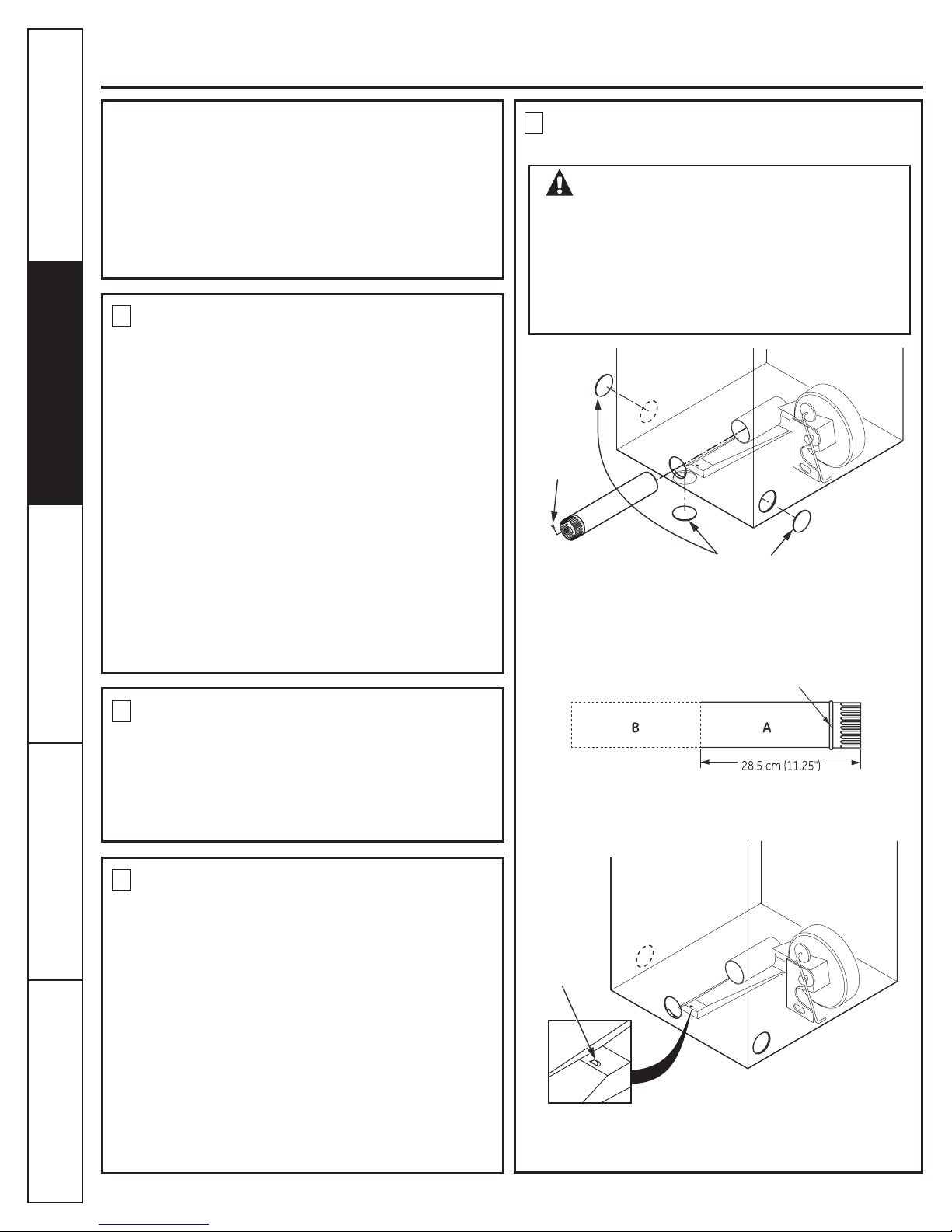
9
DRYER EXHAUST TO RIGHT, LEFT OR
BOTTOM CABINET
WARNING - BEFORE PERFORMING
THIS EXHAUST INSTALLATION, BE SURE
TO DISCONNECT THE DRYER FROM ITS
ELECTRICAL SUPPLY. PROTECT YOUR
HANDS AND ARMS FROM SHARP EDGES
WHEN WORKING INSIDE THE CABINET.
BE SURE TO WEAR GLOVES.
REMOVE
SCREW
AND SAVE.
REMOVE
DESIRED
KNOCKOUT
(ONE ONLY).
Detach and remove the bottom, right or left side knockout as
desired. Remove the screw inside the dryer exhaust duct and
save. Pull the duct out of the dryer.
FIXING HOLE
7
Operating Instructions Installation InstructionsTroubleshooting Tips
BATHROOM OR BEDROOM
INSTALLATION
• The dryer MUST be vented to the outdoors. See EXHAUST
INFORMATION section 3 & 4.
• The installation must conform with local codes or, in the
absence of local codes, with the current CSA C22.1 Canadian
Electrical code part 1.
8
MOBILE OR MANUFACTURED HOME
INSTALLATION
• Installation must conform to the current CAN/CSA Z240 MH
series Mobile Home Installation Codes.
• The dryer MUST be vented to the outdoors with the
termination securely fastened to the mobile home structure.
(See EXHAUST INFORMATION section 3 & 4.)
• The vent MUST NOT be terminated beneath a mobile or
manufactured home.
• The vent duct material MUST BE METAL.
• Do not use sheet metal screws or other fastening devices
which extend into the interior of the exhaust vent.
• See section 2 for electrical connection information.
Consumer Support
10
Cut the duct as shown and keep portion A.
TAB LOCATION
BEND TAB
UP 45º
Through the rear opening, locate the tab in the middle of the
appliance base. Lift the tab to about 45º using a at blade
screwdriver.
Page 11

Electric Dryer
Safety Instructions
www.GEAppliances.ca
ADDING NEW DUCT
FIXING
HOLE
PORTION “A”
RIGHT OR
LEFT SIDE
EXHAUST
Reconnect the cut portion (A) of the duct to the blower housing.
Make sure that the shortened duct is aligned with the tab in the
base. Use the screw saved previously to secure the duct in place
through the tab on the appliance base.
ADDING ELBOW AND DUCT FOR EXHAUST
TO LEFT OR RIGHT SIDE OF CABINET
• Preassemble 10 cm (4”) elbow with 10 cm (4”) duct. Wrap duct
tape around joint.
• Insert duct assembly, elbow rst , through the side opening and
connect the elbow to the dryer internal duct.
DRYER EXHAUST TO RIGHT, LEFT OR
BOTTOM CABINET
• Insert the elbow through the rear opening and connect it to the
dryer internal duct.
• Apply duct tape on the joint between the dryer internal duct
and elbow, as shown on page 11.
CAUTION:
Internal duct joints must be secured with tape,
otherwise they may separate and cause a
safety hazard.
ADDING COVER PLATE TO REAR OF
CABINET (SIDES AND BOTTOM EXHAUST)
Installation Instructions
Operating Instructions
CAUTION: Be sure not to pull or damage the
electrical wires inside the dryer when
inserting the duct.
EXHAUST CAN BE
ADDED TO LEFT OR
RIGHT SIDE
• Apply duct tape as shown on the joint between the dryer
internal duct and the elbow.
DUCT
TAPE
CAUTION:
Internal duct joints must be
secured with tape, otherwise
they may separate and cause
a safety hazard.
PLATE
(KIT WE1M454)
Connect standard metal elbows and ducts to complete the
exhaust system. Cover back opening with a plate (Kit
WE1M454) available from your local service provider. Place
dryer in nal location.
WARNING - NEVER LEAVE THE BACK
OPENING WITHOUT THE PLATE. (Kit WE1M454)
10
SERVICING
WARNING - LABEL ALL WIRES PRIOR
TO DISCONNECTING WHEN SERVICING
CONTROLS. WIRING ERRORS CAN CAUSE
IMPROPER AND DANGEROUS OPERATION
AFTER SERVICING/INSTALLATION.
For servicing phone numbers for replacement parts, and other
information, refer to Owner’s Manual or visit our Web site.
Troubleshooting Tips
Consumer Support
11
Page 12

Gas Dryer
Safety Instructions
BEFORE YOU BEGIN:
Read these instructions completely and carefully.
IMPORTANT - Save these instructions for local
inspector’s use.
IMPORTANT - Observe all governing codes and
ordinances.
Note to Installer - Be sure to leave these instructions with the
customer.
Note to Customer - Keep these instructions with your Use
and Care Book for future reference.
Before the old dryer is removed from service or discarded,
remove the dryer door.
Service information and the wiring diagram are located in the
control console.
Install the dryer where the temperature is above 10° C (50°F)
for satisfactory operation of the dryer control system.
NOTE: Installation and service of this dryer requires basic mechanical and electrical skills. It is your responsibility to contact a
qualied installer to make the electrical connections.
WARNING!
FOR YOUR SAFETY:
Use only rigid metal or exible metal 4-in. diameter
ductwork for exhausting to the outdoors. Never use plastic
or other combustible, easy-to-puncture ductwork.
This appliance must be properly grounded and installed as
described in these instructions.
Do not install or store appliance in an area where it will be
exposed to water and/or weather.
This dryer must be exhausted to the outdoors.
Inspect the dryer exhaust outlet and straighten the outlet
walls if they are bent.
Do not allow children on or in the appliance. Close
supervision of children is necessary when the appliance is
used near children.
TOOLS YOU
WILL NEED
Operating Instructions Installation InstructionsTroubleshooting Tips
10 in. ADJUSTABLE WRENCHES (2)
8 in. PIPE WRENCH
Step 1 Verify your gas installation (see section2).
Step 2 Prepare the area and exhaust for installation of
new dryer (see section 1).
Step 3 Check and ensure the existing external exhaust is
clean (see section 1) and meets attached
installation specications (see section 6).
Step 4 Remove the foam shipping pads (see section 1).
Step 5 Move the dryer to the desired location.
Step 6 Level your dryer (see section 8).
Step 7 Connect the gas supply (see section 3) and check
for leaks (see section 4)
SLIP JOINT PLIERS
LEVEL
FLAT BLADE SCREWDRIVER
1O cm (4 in.)
METAL ELBOW
PIPE COMPOUND
FLEXIBLE GAS LINE CONNECTOR
METAL DUCT (RECOMMENDED)
1O cm (4 in.) DIA. FLEXIBLE METAL
Step 8 Connect the external exhaust (see section 7).
Step 9 Connect the power supply (see section 5).
Step 10 Check the operation of the power supply, gas
connections and venting.
Step 11 Place the Use and Care in a location where
it will be noticed by the owner.
For alcove or closet installation, see section 9.
For bathroom or bedroom installation, see section 10.
For mobile or manufactured home see, section 11.
MATERIALS YOU
WILL NEED
1O cm (4 in.) DIA.
DUCT (IF NEEDED)
GLOVES
1O cm (4
in.) DUCT
CLAMPS (2)
SAFETY GLASSES
SOAP SOLUTION FOR
LEAK DETECTION
EXHAUST HOOD
DUCT TAPE
Consumer Support
12
Page 13

Gas Dryer
www.GEAppliances.ca
Minimum Clearance Other Than Alcove or Closet Installation
Minimum clearance to combustible surfaces and for air opening are: 0 cm (0 in.) clearance both sides and 2.5 cm (1 in.) rear.
Consideration must be given to provide adequate clearance for installation and service.
Safety Instructions
1
PREPARING FOR INSTALLATION
OF NEW DRYER
CSA (AGA) APPROVED
NEW FLEXIBLE GAS
LINE CONNECTOR
EXTERNAL
DUCT
OPENING
DUCT
TAPE
10 cm (4 in.) METAL DUCT
VENT
PROTECTION
BRACKET
GAS
INLET
PIPE
DUCT
TAPE
Pull the vent protection bracket
out until it stops, and let it rest on
the oor. The bracket prevents
the unit from moving too close
to the wall and crushing the
rear vent. Prolong by adding a
DASHED FLEXIBLE duct.
TIP: Install your dryer before installing your washer.
This will allow better access when installing dryer exhaust.
DISCONNECTING GAS
TURN GAS
SHUT-OFF
VALVE TO THE
OFF POSITION.
DISCONNECT AND DISCARD OLD
FLEXIBLE GAS CONNECTOR AND
OLD DUCTING MATERIAL
Tilt the dryer sideways
and remove the foam
shipping pads by pulling
at the sides and breaking
them away from the
dryer legs. Be sure to
remove all of the foam
pieces around the legs.
2
GAS REQUIREMENTS
WARNING!
• Installation must conform to local codes and ordinances,
or in their absence, the NCAN/CGA-B149, Natural Gas,
Installation.
• This gas dryer is equipped with a Valve & Burner Assembly
for use only with natural gas. Using conversion kit
WE25M43, your local service organization can convert this
dryer for use with propane (LP) gas. ALL CONVERSIONS
MUST BE MADE BY PROPERLY TRAINED AND QUALIFIED
PERSONNEL AND IN ACCORDANCE WITH LOCAL
CODES AND ORDINANCE REQUIREMENTS OF THE CAN/
CGA-B149.1 AND B149.2 INSTALLATION CODE.
• The dryer must be disconnected from the gas supply
piping system during any pressure testing of that system
at a test pressure in excess of 0.5 PSI (3.4 KPa).
• The dryer must be isolated from the gas supply piping
system by closing the equipment shut-off valve during any
pressure testing of the gas supply piping of test pressure
equal to or less than 0.5 PSI (3.4 KPa).
DRYER GAS SUPPLY CONNECTION
5 cm (2")
Installation Instructions
Operating Instructions
Troubleshooting Tips
WARNING - NEVER REUSE OLD
FLEXIBLE CONNECTORS.
The use of old exible connectors can cause leaks and
personal injury. Always use new exible connectors when
installing gas appliances.
REMOVING LINT FROM WALL EXHAUST
OPENING
WALL
INTERNAL DUCT
OPENING
CHECK THAT EXHAUST HOOD
DAMPER OPENS AND CLOSES
FREELY.
6.6 cm (2-5/8")
0.9 cm (3/8")
NOTE: Add to vertical dimension
the distance between cabinet
bottom to oor.
NPT MALE THREAD GAS SUPPLY
GAS SUPPLY
• A 0.3 cm (1/8-in.) National Pipe Taper thread plugged tapping,
accessible for test gauge connection, must be installed
immediately upstream of the gas supply connection to
the dryer. Contact your local gas utility should you have
questions on the installation of the plugged tapping.
• Supply line is to be 1.2 cm (1/2-in.) rigid pipe and equipped
with an accessible shut-off within 2 m (6 ft.) of, and in the
same room with, the dryer.
• Use pipe thread sealer compound appropriate for natural or
LP gas or use Teon tape.
• You must use with this dryer a exible metal connector listed
connector ANSI Z21.24 / CSA 6.10.
• Connect exible metal connector to dryer and gas supply.
• Open shut-off valve.
Consumer Support
13
Page 14
Gas Dryer
3
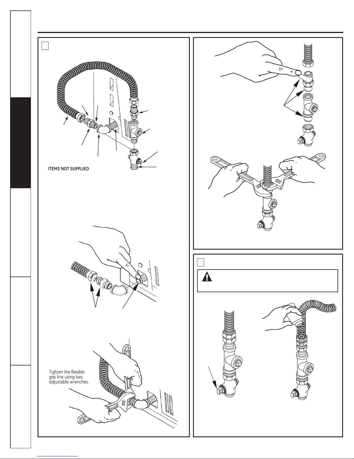
Listed connector ANSIZ21.24 / CSA 6.10
Safety Instructions
RECONNECTING GAS
FLARE
NEW METAL
FLEXIBLE GAS LINE
CONNECTOR
ADAPTER
Note: The connector and ttings are designed for use only on the
original installation and are not to be reused for another appliance or
at another location. Keep are end of adapter free of grease, oil and
thread sealant.
Caution: Use adapters as shown. Connector nuts must not be
connected directly to pipe threads.
Operating Instructions Installation InstructionsTroubleshooting Tips
NPT
ELBOW
0.9 cm
(3/8") NPT
ADAPTER
0.3 cm (1/8") NPT
PIPE PLUG FOR
CHECKING GAS
INLET PRESSURE
SHUT-OFF
VALVE
PIPE SIZE
AT LEAST
1.2 cm (1/2")
APPLY PIPE COMPOUND
TO ALL MALE THREADS.
Tighten all connections using two adjustable wrenches.
Do not overtorque gas connections!
4
LEAK TEST
WARNING - NEVER USE AN OPEN
FLAME TO TEST FOR GAS LEAKS.
APPLY PIPE COMPOUND
TO THE ADAPTER AND
DRYER GAS INLET.
Consumer Support
14
OPEN GAS
VALVE.
Check all connections for leaks with soapy solution or equivalent.
Apply soap solution. Leak test solution must not contain ammonia
which could cause damage to the brass ttings. If leaks are
found, close valve, retighten the joint, and repeat the soap test .
Page 15

Gas Dryer
Safety Instructions
www.GEAppliances.ca
5
ELECTRICAL CONNECTION
INFORMATION
WARNING - TO REDUCE THE RISK OF FIRE,
ELECTRICAL SHOCK AND PERSONAL INJURY:
DO NOT USE AN EXTENSION CORD OR AN
ADAPTER PLUG WITH THIS APPLIANCE.
Dryer must be electrically grounded in accordance with local
codes and ordinances, or in the absence of local codes, in
accordance with the current CSA C22.1 Canadian Electrical
code part 1. Improper connection of the equipment-grounding
conductor can result in an electric shock. Check with a
qualied electrician or service representative or personnel
if you are in doubt as to whether the appliance is properly
grounded.
Do not modify the plug provided with the appliance: if it will
not t the outlet, have a proper outlet installed by a qualied
electrician.
ELECTRICAL REQUIREMENTS
This appliance must be supplied with 120V, 60Hz, and connected
to a properly grounded branch circuit, protected by a 15- or 20amp circuit breaker or time-delay fuse. If electrical supply provided
does not meet the above specications, it is recommended that a
licensed electrician install an approved outlet.
WARNING - THIS DRYER IS EQUIPPED
WITH A THREE-PRONG (GROUNDING) PLUG FOR
YOUR PROTECTION AGAINST SHOCK HAZARD AND
SHOULD BE PLUGGED DIRECTLY INTO A PROPERLY
GROUNDED THREE-PRONG RECEPTACLE. DO NOT
CUT OR REMOVE THE GROUNDING PRONG FROM
THIS PLUG. INSTALLATION MUST BE IN ACCORDANCE
WITH THE CURRENT CSA C22.1 CANADIAN
ELECTRICAL CODE PART 1 AND/OR LOCAL CODES.
IF LOCAL CODES PERMIT, AN EXTERNAL
GROUND WIRE (NOT PROVIDED), WHICH MEETS
LOCAL CODES, MAY BE ADDED BY ATTACHING TO THE GREEN
GROUND SCREW ON THE REAR OF THE DRYER, AND TO A GROUNDED
METAL COLD WATER PIPE OR OTHER ESTABLISHED GROUND.
6
EXHAUST INFORMATION
WARNING - USE ONLY METAL 10 cm (4in.)
DUCT. DO NOT USE DUCT LONGER THAN
SPECIFIED IN THE EXHAUST LENGTH TABLE.
Using exhaust longer than specied length will:
• Increase the drying times and the energy cost.
• Reduce the dryer life.
• Accumulate lint, creating a potential re hazard.
The correct exhaust installation is YOUR RESPONSIBILITY.
Problems due to incorrect installation are not covered by
the warranty.
The MAXIMUM ALLOWABLE length of the exhaust system
depends upon the type of duct, number of turns, the type of
exhaust hood (wall cap), and all conditions noted below. Both
rigid and exible metal duct are shown in the table below.
EXHAUST LENGTH
If using exible metal duct, please refer to page 18.
EXHAUST SYSTEM CHECKLIST
HOOD OR WALLCAP
• Terminate in a manner to prevent back drafts or entry of birds or other
wildlife.
• Termination should present minimal resistance to the exhaust air ow
and should require little or no maintenance to prevent clogging.
• Never install a screen in or over the exhaust duct.
• Wall caps must be installed at least 30 cm (12 in.) above ground level or
any other obstruction with the opening pointed down.
• If roof vents or louvered plenums are used, they must be equivalent to
a 10 cm (4 in. ) dampened wall cap in regard to resistance to air ow,
prevention of back drafts, and maintenance required to prevent clogging.
SEPARATION OF TURNS
For best performance, separate all turns by at least 1.2 m (4 ft.) of straight
duct, including distance between last turn and dampened wall cap.
TURNS OTHER THAN 90º
• One turn of 45º or less may be ignored.
• Two 45º turns should be treated as one 90º turn.
• Each turn over 45º should be treated as one 90º turn.
SEALING OF JOINTS
• All joints should be tight to avoid leaks. The male end of each section of
duct must point away from the dryer.
• Do not assemble the ductwork with fasteners that extend into the duct.
They will serve as a collection point for lint.
• Duct joints should be made air- and moisture-tight by wrapping the
overlapped joints with duct tape.
• Horizontal runs should slope down toward the outdoors 1.2cm (1/2 in.) /ft.
INSULATION
Duct work that runs through an unheated area or is near air conditioning
should be insulated to reduce condensation and lint build-up.
Installation Instructions
Operating Instructions
Troubleshooting Tips
Consumer Support
15
Page 16

Gas Dryer
7
OF FIRE OR PERSONAL INJURY:
This dryer must be exhausted to the outdoors.
Safety Instructions
• Use only metal duct.
• Do not terminate exhaust in a chimney, any gas
• Provide an access for inspection and cleaning of
• Never terminate the exhaust into a common duct
• Do not obstruct incoming or exhausted air.
WE RECOMMEND THAT YOU INSTALL YOUR DRYER BEFORE
YOUR WASHER. THIS WILL PERMIT DIRECT ACCESS FOR
EASIER EXHAUST CONNECTION.
EXHAUST CONNECTION
WARNING - TO REDUCE THE RISK
vent, under an enclosed oor (crawl space), or into
an attic. The accumulated lint could create a re
hazard.
the exhaust system, especially at turns. Inspect and
clean at least once a year.
with a kitchen exhaust. A combination of lint and
grease could create a re hazard.
ELBOW HIGHLY
RECOMMENDED
RECOMMENDED
CONFIGURATION
TO MINIMIZE
EXHAUST
BLOCKAGE.
ELBOW HIGHLY
RECOMMENDED
THIS DRYER COMES READY FOR REAR EXHAUSTING. IF
SPACE IS LIMITED, USE THE INSTRUCTIONS IN SECTION 12 TO
EXHAUST DIRECTLY FROM THE LEFT SIDE OR BOTTOM OF THE
CABINET.
STANDARD REAR EXHAUST
Operating Instructions Installation InstructionsTroubleshooting Tips
NOTE: ELBOWS WILL PREVENT DUCT KINKING
AND COLLAPSING.
8
LEVELING DRYER
Stand the dryer upright near the nal location and
adjust the 4 leveling legs to match the height of your
washer.
LEVEL
FRONT-TO-BACK
LEVEL
SIDE-TO-SIDE
WE STRONGLY RECOMMEND THE USE OF
RIGID METAL EXHAUST DUCT. IF USING
FLEXIBLE METAL DUCT, CUT IT TO THE
PROPER LENGTH AND AVOID BUNCHING
OF THE DUCT BEHIND THE DRYER.
Consumer Support
16
4 LEVELING
LEGS
Page 17

Gas Dryer
USING FLEXIBLE METAL DUCTS EXHAUSTING
If rigid all-metal duct cannot be used, then exible all-metal
venting can be used, but it will reduce the maximum
recommended duct length. In special installations when it is
impossible to use only metal ducting, then UL-listed clothes dryer
exible metal transition duct may be used as transition venting
between the dryer and wall connection only. The use of this
ducting will affect dry time.
If exible transition duct is necessary, the following directions
must be followed.
• Use the shortest length possible.
• Stretch the duct to its maximum length to avoid kinks.
• Do not crush or collapse the duct.
• Extend vent protection bracket as described in step 1 on
page 2.
• Never use transition duct inside the wall or inside the dryer.
• Avoid resting the duct on sharp objects.
• Venting must conform to local building codes.
DO
ELBOW HIGHLY
RECOMMENDED
A CLOTHES DRYER PRODUCES COMBUSTIBLE LINT. FOR
ALL INSTALLATIONS, THE DRYER MUST BE CONNECTED
TO AN EXHAUST TO THE OUTDOORS.
NOTE: MOBILE HOME, BEDROOM, BATHROOM, ALCOVE
OR CLOSET INSTALLATIONS MUST BE EXHAUSTED TO
THE OUTDOORS.
9
ALCOVE OR CLOSET INSTALLATION
• If your dryer is approved for installation in an alcove or closet,
it will be stated on a label on the dryer back.
• The dryer MUST be vented to the outdoors. See the EXHAUST
INFORMATION sections 3 & 4.
• Minimum clearance between dryer cabinet and adjacent walls
or other surfaces is:
0 in. either side
7.6 cm (3 in.) front and rear
• Minimum vertical space from oor to overhead cabinets,
ceiling, etc. is 109 cm (43 in.) without pedestal, 140 cm (55 in.)
with pedestal.
• Closet doors must be louvered or otherwise ventilated and
must contain a minimum of 387 sq. cm (60 sq. in.) of open area
equally distributed. If the closet contains both a washer and
a dryer, doors must contain a minimum of 774 sq. cm (120 sq.
in.) of open area equally distributed.
• The closet should be vented to the outdoors to prevent gas
pocketing in case of a gas leak in the supply line.
• No other fuel-burning appliance shall be installed in the same
closet with the dryer.
NOTE: WHEN THE EXHAUST DUCT IS LOCATED AT THE
REAR OF THE DRYER, MINIMUM CLEARANCE FROM THE
WALL IS 14 cm (5.5 IN.)
Safety Instructions
www.GEAppliances.ca
Installation Instructions
Operating Instructions
DO NOT USE
EXCESSIVE
EXHAUST
LENGTH
ELBOW HIGHLY
RECOMMENDED
DON’T
DO NOT SIT
DRYER ON
FLEXIBLE
EXHAUST
DO NOT
CRUSH
FLEXIBLE
EXHAUST
AGAINST
WALL
10
BATHROOM OR BEDROOM
INSTALLATION
• The dryer MUST be vented to the outdoors. See EXHAUST
INFORMATION section 6.
• The installation must conform with local codes or, in the
absence of local codes, with the current CSA C22.1 Canadian
Electrical code part 1.
11
MOBILE OR MANUFACTURED HOME
INSTALLATION
• Installation must conform to the current CAN/CSA Z240 MH
series Mobile Home Installation Codes.
• The dryer MUST be vented to the outdoors with the
termination securely fastened to the mobile home structure.
(See EXHAUST INFORMATION section 6.)
• The vent MUST NOT be terminated beneath a mobile or
manufactured home.
• The vent duct material MUST BE METAL.
• KIT 14-D346-33 MUST be used to attach the dryer securely to
the structure.
• The vent MUST NOT be connected to any other duct, vent, or
chimney.
• Do not use sheet metal screws or other fastening devices
which extend into the interior of the exhaust vent.
• Provide an opening with a free area of at least 161 cm sq. (25
sq. in.) for introduction of outside air into the dryer room.
Troubleshooting Tips
Consumer Support
17
Page 18
Gas Dryer
12
RESIDENTIAL GARAGE INSTALLATION
Dryers installed in residential garages must be elevated 18 inches
(46cm) above the oor.
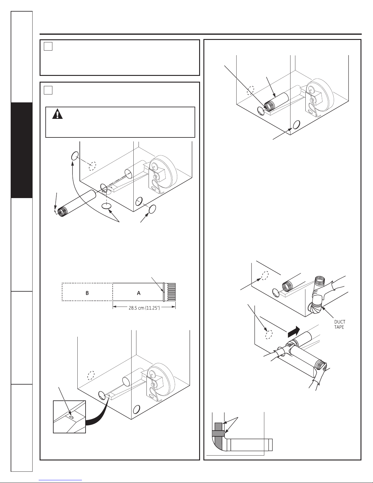
ADDING NEW DUCT
FIXING
HOLE
PORTION “A”
Safety Instructions
13
REMOVE
SCREW
AND SAVE.
Detach and remove the bottom, right or left side knockout as desired.
Remove the screw inside the dryer exhaust duct and save. Pull the
duct out of the dryer. Protect sharp edges around the knockout and
exhaust opening with the tape.
DRYER EXHAUST TO LEFT OR BOTTOM
CABINET
WARNING - PROTECT YOUR
HANDS AND ARMS FROM SHARP EDGES
WHEN WORKING INSIDE THE CABINET.
REMOVE
DESIRED
KNOCKOUT
(ONE ONLY).
FIXING HOLE
RIGHT OR
LEFT SIDE
EXHAUST
Reconnect the cut portion (A) of the duct to the blower housing.
Make sure that the xing hole is aligned with the tab in the
base. Use the screw saved previously to secure the duct in place
through the tab on the appliance base.
ADDING ELBOW AND DUCT FOR EXHAUST
TO RIGHT SIDE OF CABINET
• Preassemble 10 cm (4”) elbow with 10 cm (4”) duct. Wrap duct
tape around joint.
• Insert duct assembly, elbow rst , through the side opening and
connect the elbow to the dryer internal duct.
CAUTION: Be sure not to pull or damage the
electrical wires inside the dryer when
inserting the duct.
Operating Instructions Installation InstructionsTroubleshooting Tips
Cut the duct as shown and keep portion A.
TAB LOCATION
BEND TAB
UP 45º
Through the rear opening, locate the tab in the middle of the
appliance base. Lift the tab to about 45º using a at blade
screwdriver.
Consumer Support
18
EXHAUST CAN BE
ADDED TO LEFT OR
RIGHT SIDE
• Apply duct tape as shown on the joint between the dryer
internal duct and the elbow.
DUCT
TAPE
CAUTION:
Internal duct joints must be
secured with tape, otherwise
they may separate and cause
a safety hazard.
Page 19

Gas Dryer
ADDING ELBOW FOR EXHAUST
THROUGH BOTTOM OF CABINET
• Insert the elbow through the rear opening and connect it to the
dryer internal duct.
• Apply duct tape on the joint between the dryer internal duct
and elbow, as shown on page 7.
CAUTION:
Internal duct joints must be secured with tape,
otherwise they may separate and cause a
safety hazard.
www.GEAppliances.ca
14
SERVICING
WARNING - LABEL ALL WIRES PRIOR
TO DISCONNECTING WHEN SERVICING
CONTROLS. WIRING ERRORS CAN CAUSE
IMPROPER AND DANGEROUS OPERATION
AFTER SERVICING/INSTALLATION.
For servicing phone numbers for replacement parts, and other
information, refer to Owner’s Manual or visit our Web site.
Safety Instructions
Installation Instructions
Operating Instructions
ADDING COVER PLATE TO REAR OF
CABINET
PLATE
(KIT WE1M454)
Connect standard metal elbows and ducts to complete the
exhaust system. Cover back opening with a plate (Kit
WE1M454) available from your local service provider. Place
dryer in nal location.
WARNING - NEVER LEAVE THE BACK
OPENING WITHOUT THE PLATE. (Kit WE1M454)
Troubleshooting Tips
Consumer Support
19
Page 20

Reversing the door
Tools needed:
Safety Instructions
Phillips screwdriver
1. Open the door and remove the filler plugs opposite the hinges. With the
door completely open, remove the bottom screw from each hinge on the
dryer face. Insert these screws about half way into the TOP holes, for each
hinge, on the opposite side (where you removed the filler plugs). Apply firm
pressure to get the screw started in new holes.
2. Loosen the top screw from each hinge on the dryer face half way. With one
hand holding the top of the door and the other hand holding the bottom,
remove the door from the dryer by lifting it UP and OUT.
Tape-tipped
putty knife
Operating Instructions Installation InstructionsTroubleshooting Tips
3. Rotate the door 180°. Insert it on the opposite side of the opening by moving
the door IN and DOWN until the top hinge and the bottom hinge are resting
on the top screws inserted in step 1.
4. Remove the remaining screws from the side of the opening from which the
door was removed. With these screws, secure each hinge at the bottom.
Tighten the two top screws of each hinge. Reinsert the plastic plugs on the
side from which the door was removed.
Consumer Support
20
Page 21

About the dryer control panel
You can locate your model number on the label on the front of the dryer behind the door. Throughout
this manual, features and appearance may vary from your model.
Model MTMX100EM
www.GEAppliances.ca
Safety Instructions
Installation Instructions
3
Model HTMX100EM
3
Models GTMX100EM
GTMX100GM
1
2
Operating Instructions
1
2
Troubleshooting Tips
3
1
Models GTMP200EM
GTMP200GM
3
1
2
Consumer Support
2
21
Page 22

About the dryer control panel
You can locate your model number on the label on the front of the dryer behind the door. Throughout
this manual, features and appearance may vary from your model.
Models GTMP400EM
GTMP400GM
Safety Instructions
1
2
Models GTMN500EM
GTMN500GM
3
Operating Instructions Installation InstructionsTroubleshooting Tips
3
1
2
NOTE: Drying times will vary according to the type of heat used (Electric,
Natural or LP gas), size of load, types of fabrics, wetness of clothes and
condition of exhaust ducts.
Consumer Support
22
Page 23

About the control settings
Important: Clean the lint lter each time you use the dryer.
Fabric Care/Temperature (on some models)
1
REGULAR
or COTTONS
REG. HEAT
For regular to heavy cottons.
Safety Instructions
www.GEAppliances.ca
MEDIUM,
EASY CARE
MED. HEAT,
EASY CARE
or PERMA PRESS
MED. HEAT
DELICATES
LOW HEAT
FLUFF
NO HEAT
Automatic cycles automatically determine fabric dryness. Select LESS DRY if you want your clothes slightly
damp at the end of the drying cycle. Select MORE DRY if you want them to feel drier. Timed cycles run for a
selected time.
Drying Cycles
2
COTTONS
EASY CARE/
PERMANENT PRESS
DELICATES
For synthetics, blends, delicates and items labeled permanent press.
On some models. For delicates, synthetics and items labeled tumble dry low.
For ufng items without heat. Use the TIMED DRY cycle.
For cottons and most linens. For most loads, select OPTIMUM DRY (on some models) or select the
Preferred Regular Setting marked with an *.
For wrinkle-free, permanent press and delicate items, and knits.
For delicate items, special-care fabrics and knits.
Installation Instructions
Operating Instructions
TIMED DRY
DAMP DRY
DEWRINKLE
QUICK FLUFF
Start — Close the dryer door. Select START. Opening the door during operation will stop the dryer. To
3
restart the dryer, close the door and select START to complete the cycle.
Set the Cycle Selector at the desired drying time.
For leaving items partially damp.
For removing wrinkles from items that are clean and dry or that are very lightly damp.
For freshening or ufng up already dry clothing, fabrics, linens and pillows. Use with FLUFF NO
HE AT. Provides 10 minutes of no heat tumbling.
Color Logic (on some models)
Select the correct FABRIC CARE setting.
Match the particular color below the words
with the same color on the Cycle Dial.
Example: Drying a load of clothing labeled
permanent press.
Choose the FABRIC CARE setting—for
1
this load it would be the EASY CARE MED.
HE AT (which is a particular color).
Turn the Cycle Dial to the area that has
2
the same color as the FABRIC CARE
setting you have chosen—for this load it
would be the EASY CARE AUTOMATIC.
Troubleshooting Tips
Consumer Support
23
Page 24

About the dryer features
Wrinkle Care (on some models)
Safety Instructions
Use this option to minimize the wrinkles
in clothes. It provides approximately
15 minutes of no-heat tumbling after
the clothes are dry.
This option can only be used with the
COTTONS and
EASY CARE cycles.
Cycle Signal Option (on some models)
This signal will sound just before the end
of the cycle to remind you to remove the
clothes. On some models, the signal sound
level cannot be adjusted.
If you selected the WRINKLE CARE option,
the signal will sound at the end of the drying
time and will sound several times during the
WRINKLE CARE cycle. This will remind you
that it is time to remove the clothes.
If you are using the CYCLE SIGNAL knob
and you select the WRINKLE CARE option,
a signal will sound at the end of the drying time
and several times during the WRINKLE CARE
cycle. This will remind you that it is time to
remove the clothes.
If WRINKLE CARE is not on, the dryer
will stop once the timer reaches the
WRINKLE CARE mark on the cycle dial.
NOTE:
Remove garments promptly at the sound
of the signal. Place clothes on hangers so
wrinkles won’t set in.
Use the Cycle Signal especially when
drying fabrics like polyester knits and
permanent press. These fabrics should
be removed so wrinkles won’t set in.
Operating Instructions Installation InstructionsTroubleshooting Tips
Automatic Cycle Signal (on some models)
At the end of each cycle, there is
approximately 15 minutes of no-heat
tumbling after the laundry is dry.
A reminder signal will sound periodically
during this time to remind you to
remove the laundry.
Drum Lamp
Before replacing the light bulb, be sure to unplug the dryer power cord or disconnect
the dryer at the household distribution panel by removing the fuse or switching off the
circuit breaker. Reach above dryer opening from inside the drum. Remove the bulb and
replace with the same size bulb.
Stainless Steel Drum
The stainless steel used to make the dryer drum provides the highest reliability
available in a GE dryer. If the dryer drum should be scratched or dented during normal
use, the drum will not rust or corrode. These surface blemishes will not affect the
function or durability of the drum.
(on some models)
Consumer Support
24
Page 25

Loading and using the dryer
Always follow the fabric manufacturer’s care label when laundering.
Sorting and Loading Hints
Safety Instructions
www.GEAppliances.ca
As a general rule, if clothes are sorted properly for
the washer, they are sorted properly for the dryer.
Try also to sort items according to size. For example,
do not dry a sheet with socks or other
small items.
Do not add fabric softener sheets once the load
has become warm. They may cause fabric softener
stains. Bounce
been approved for use in all GE Dryers when used
in accordance with the manufacturer’s instructions.
®
Fabric Conditioner Dryer Sheets have
Care and Cleaning of the Dryer
The Exterior: Wipe or dust any spills or washing
compounds with a damp cloth. Dryer control
panel and nishes may be damaged by some
laundry pretreatment soil and stain remover
products. Apply these products away from the
dryer. The fabric may then be washed and dried
normally. Damage to your dryer caused by
these products is not covered by your warranty.
The Lint Filter: Clean the
lint lter before each use.
Pull out the lint lter.
Moisten your ngers and
remove the captured lint.
Once clean, slide the lter
back into position. Have a
qualied technician vacuum
the lint from the dryer once a year.
Do not overload. This wastes energy and causes
wrinkling.
Do not dry the following items: berglass items,
woolens, rubber-coated items, plastics, items with
plastic trim and foam-lled items.
Stainless Steel: To clean stainless steel surfaces,
use a damp cloth with a mild, non-abrasive cleaner
suitable for stainless steel surfaces. Remove the
cleaner residue, and then dry with a clean cloth.
The Exhaust Duct: Inspect and clean the exhaust
ducting at least once a year to prevent clogging.
A partially clogged exhaust can lengthen the
drying time.
Follow these steps:
Turn off electrical supply by disconnecting
1
the plug from the wall socket.
Disconnect the duct from the dryer.
2
Vacuum the duct with the hose attachment
and reconnect the duct.
3
The Exhaust Hood: Check with a mirror that
the inside aps of the hood move freely when
operating. Make sure that there is no wildlife
(birds, insects, etc.) nesting inside the duct or hood.
Installation Instructions
Operating Instructions
Troubleshooting Tips
Consumer Support
25
Page 26

Before you call for service...
Troubleshooting Tips
Save time and money! Review the charts on the following
pages, or visit GEAppliances.ca. You may not need to call
for service.
PROBLEM Possible Causes What To Do
Safety Instructions
Dryer doesn’t start
Dryer doesn’t heat
Dryer shakes or
makes noise
Greasy spots on clothes
Lint on clothes
Dryer is unplugged
Fuse is blown/circuit breaker
is tripped
Fuse is blown/circuit breaker
is tripped; the dryer may
tumble but not heat
Gas service is off
Some shaking/noise is normal.
Dryer may be sitting unevenly
Improper use of fabric softener
Drying dirty items with clean
ones
Clothes were not completely
clean
Lint lter is full
• Make sure the dryer plug is pushed completely into the
outlet.
• Check the building’s fuse/circuit breaker box and replace
fuse or reset breaker. NOTE: Most electric dryers use two
fuses or breakers.
• Check the building’s fuse/circuit breaker box and replace
both fuses or reset both breakers. Your dryer may tumble if
only one fuse is blown or one breaker tripped.
• Make sure gas shutoff at dryer and main shutoff are fully
open.
• Move dryer to an even oor space, or adjust leveling legs as
necessary until even.
• Follow directions on fabric softener package.
• Use your dryer to dry only clean items. Dirty items can
stain clean items and the dryer
• Sometimes stains which cannot be seen when the
clothes are wet appear after drying. Use proper washing
procedures before drying.
• Clean lint screen before each load.
Operating Instructions Installation InstructionsTroubleshooting Tips
Static occurs
Inconsistent drying
times
Consumer Support
26
Improper sorting
Static electricity can attract lint
Overloading
Paper, tissue, etc., left in pockets
No fabric softener was used
Overdrying
Synthetics, permanent press
and blends can cause static
Type of heat
• Sort lint producers (like chenille) from lint collectors (like
corduroy).
• See suggestions in this section under STATIC.
• Separate large loads into smaller ones.
• Empty all pockets before laundering clothes.
• Try a fabric softener.
®
• Bounce
approved for use in all GE Dryers when used in accordance
with the manufacturer’s instructions.
• Try a fabric softener.
• Adjust setting to LESS DRY or DAMP.
• Try a fabric softener.
• Automatic drying times will vary according to the type of
heat used. If you recently changed from an electric to a gas
(natural or LP) dryer, or vice versa, the drying time could be
different.
Fabric Conditioner Dryer Sheets have been
Page 27

Before you call for service...
PROBLEM Possible Causes What To Do
Safety Instructions
www.GEAppliances.ca
Clothes take too long to
dry
Clothes are wrinkled
Improper or obstructed ducting
Improper sorting
Large loads of heavy fabrics
(like beach towels)
Controls improperly set
Lint lter is full
Blown fuses or tripped circuit
breaker
Overloading/combining loads
Underloading
Overdrying
• Check the Installation Instructions to make sure the dryer
venting is correct.
• Make sure ducting is clean, free of kinks and unobstructed.
• Check to see if outside wall damper operates easily.
• Separate heavy items from lightweight items (generally, a
well-sorted washer load is a well-sorted dryer load).
• Large, heavy fabrics contain more moisture and take
longer to dry. Separate large, heavy fabrics into smaller
loads to speed drying time.
• Match control settings to the load you are drying.
• Clean lint lter before every load.
• Replace fuses or reset circuit breakers. Since most dryers
use 2 fuses/breakers, make sure both are operating.
• Do not put more than one washer load in the dryer at a
time.
• If you are drying only one or two items, add a few items to
ensure proper tumbling.
• Select a shorter drying time.
• Remove items while they still hold a slight amount of
moisture. Select a LESS DRY or DAMP setting.
Installation Instructions
Operating Instructions
Clothes shrink
Letting items sit in dryer after
cycle ends
Overloading
Some fabrics will naturally
shrink when washed. Others
can be safely washed, but will
shrink in the dryer
• Remove items when cycle ends and fold or hang
immediately.
• Separate large loads into smaller ones.
• To avoid shrinkage, follow garment care labels exactly.
• Some items may be pressed back into shape after drying.
• If you are concerned about shrinkage in a particular item,
do not machine wash or tumble dry it.
Troubleshooting Tips
Consumer Support
27
Page 28

Notes
Safety Instructions
Operating Instructions Installation Instructions
Troubleshooting Tips
Consumer Support
28
Page 29

GE Dryer Warranty (For customers in Canada)
Safety Instructions
www.GEAppliances.ca
All warranty service provided by our Factory Service
Centers, or an authorized Customer Care
schedule service, call 1-800-561-3344, 24 hours a day, 7
days a week.
For The Period Of:
One Year
From the date of the
original purchase
We Will Replace:
Any part of the dryer which fails due to a defect in materials or workmanship. During this
full one-year warranty, Mabe will also provide, free of charge, all labor and related service
costs to replace the defective part.
What Is Not Covered:
Service trips to your home to teach you how to
use the product.
Improper installation, delivery or maintenance.
Failure of the product if it is abused, misused or
used for other than the intended purpose or used
commercially.
Replacement of house fuses or resetting of
circuit breakers.
Staple your receipt here.
®
technician. To
Damage to the product caused by accident, re,
oods or acts of God.
Incidental or consequential damage caused by
possible defects with this appliance.
Damage caused after delivery.
Proof of the original purchase
date is needed to obtain service
under the warranty.
Installation Instructions
Operating Instructions
This warranty is extended to the original purchaser and any succeeding owner for products purchased
for home use within Canada. In-home warranty service will be provided in areas where it is available and deemed
reasonable by Mabe to provide.
Warrantor: Mabe Canada Inc., Burlington, ON L7R 5B6
Troubleshooting Tips
Consumer Support
29
Page 30

Consumer Support
GE Appliances Website
Have a question or need assistance with your appliance? Try the GE Appliances Website 24 hours a day, any
day of the year! For greater convenience and faster service, you can now download Owner’s Manuals, order
parts, catalogs, or even schedule service on-line. You can also “Ask Our Team of Experts™ “ your questions
and so much more...
Schedule Service
Expert Mabe repair sevice is only one step away from your door. Get on-line and schedule your service at
your convenience 24 hours any day of the year! Call 1.800.561.3344 during normal business hours.
1.800.561.3344 or GEAppliances.ca
GEAppliances.ca
Real Life Design Studio
GE supports the Universal Design concept---products, services and environments that can be used by
people of all ages, sizes and capabilities. We recognize the need to design for a wide range of physical and
mental abilities and impairments. For details of GE’s Universal Design applications, including kitchen design
ideas for people with disabilities, check out our Website today.
In Canada, contact: Director, Consumer Relations, Mabe Canada Inc.
Suite 310, 1 Factory Lane
Moncton, N.B. E1C 9M3
Extended Warranties
1.888.261.2133 or GEAppliances.ca
Purchase a Mabe extended warranty and learn about special discounts that are available while your
warranty is still in effect. You can purchase it on-line anytime, or call 1.888.261.2133 during normal business
hours. Mabe Consumer Service will still be there after your warranty expires.
Parts and Accessories
Individuals qualied to service their own appliances can have parts or accessories sent directly to their
homes (VISA, MasterCard and Discover cards are accepted). Order on-line today, 24 hours every day or
by phone at 1.800.661.1616 during normal business hours.
Instructions contained in this manual cover procedures to be performed by any user. Other servicing
generally should be referred to qualied service personnel. Caution must be exercised, since improper
servicing may cause unsafe operation.
Contact Us
If you are not satised with the service you receive from GE, contact us on our Website with all the details
including your phone number, or write to:
Director, Consumer Relations, Mabe Canada Inc.
Suite 310, 1 Factory Lane
Moncton, N.B. E1C 9M3
Register Your Appliance
1.800.661.1616 or GEAppliances.ca
GEAppliances.ca
GEAppliances.ca
Register your new appliance on-line—at your convenience! Timely product registration will allow for
enhanced communication and prompt service under the terms of your warranty, should the need arise.
You may also mail in the pre-printed registration card included in the packing material.
Consumer Support
30
Printed in Mexico
Page 31

www.electromenagersge.ca
Mesures de sécurité 2-5
Directives d’installation 6-21
Sécheuse électrique
Sécheuse à gaz
Inversion de la porte
Directives de fonctionnement 21-25
Tableau de commande
Options et programmes
Chargement et utilisation de la
sécheuse
Conseils de dépannage 26-27
Service à la clientèle 29-30
Garantie
Service à la clientèle
• • • • • • • • • • • • • • • • • • • • • • • • • •
• • • • • • • • • • • • • • • • • • • • • • • • • •
• • • • • • • • • • • • • • • •
• • • • • • • • • • • • • • • • • • • •
• • • • • • • • • • • • • • • • •
• • • • • • • • • • • • •
• • • • • • • • • • • •
• • • • • • • • • • • • • • •
6-11
12-19
20
21-22
23-24
25
29
30
Guide d’utilisation
et d’entretien
avec directives d’installation
Note au consommateur :
Ce produit était en excellent état
à sa sortie de l’usine. S’il a été
endommagé pendant son transport
ou son installation, veuillez signaler
ces dommages immédiatement
au magasin où vous l’avez acheté.
Votre garantie couvre les défauts
des matériaux et de la fabrication,
mais pas les dommages causés
lors de la livraison. Pour plus de
renseignements sur les conditions
Sécheuses
de la garantie, consultez ce guide.
Transcrivez les numéros de
modèle et de série ci-dessous :
N° de modèle :
N° de série :
Vous les trouverez sur l’étiquette
apposée à l’avant de la sécheuse,
derrière la porte.
500A292P014 Rev.0
Page 32

MESURES DE SÉCURITÉ IMPORTANTES
LISEZ D’ABORD TOUTES LES DIRECTIVES
AVERTISSEMENT!
Pour votre sécurité, suivez les directives fournies dans le présent manuel an de
réduire au minimum les risques d’incendie, d’explosion et de chocs électriques, et de
Mesures de sécurité
prévenir les dommages matériels ainsi que les blessures graves ou mortelles.
N’entreposez pas ou n’utilisez pas
d’essence autres liquides ou vapeurs
inammables à proximité de cet appareil
ou de tout autre électroménager.
SI VOUS REMARQUEZ UNE ODEUR DE GAZ :
N’allumez pas d’allumette ou de
1
cigarette. Ne faites pas fonctionner
Directives d’installationConseils de dépannage
d’appareil à gaz ou électrique.
N’actionnez aucun interrupteur ;
2
n’utilisez aucun téléphone dans votre
édice.
Évacuez la pièce, l’édice ou les
3
environs.
L’installation et les réparations doivent
être effectuées par un installateur ou
un service de réparation qualié ou
par votre fournisseur de gaz.
Appelez immédiatement votre
4
fournisseur de gaz en utilisant
le téléphone d’un voisin. Suivez
attentivement les directives qu’il vous
donnera.
Si vous ne pouvez joindre votre
5
fournisseur de gaz, appelez les
pompiers (911).
Directives de fonctionnement
Service à la clientèle
2
Page 33

www.electromenagersge.ca
INSTALLATION ADÉQUATE
Avant d’utiliser votre sécheuse, assurez-vous qu’elle a été adéquatement installée, conformément aux
directives d’installation, présentes dans ce guide.
Mesures de sécurité
La sécheuse doit être correctement mise à la terre,
conformément à tous les codes et règlements en
vigueur. Suivez les directives d’installation.
Installez ou entreposez l’appareil à l’abri du gel et
des intempéries.
Branchez l’appareil sur un circuit protégé et de
capacité appropriée an d’éviter toute surcharge
électrique.
Retirez la pellicule protectrice de couleur sur le
tableau de commande et la porte.
Retirez tout le matériel d’emballage tranchant et
jetez tous les matériaux de transport de façon
appropriée.
Ne retirez pas le support de protection du conduit
d’évacuation à l’arrière de la sécheuse.
Tirez sur le support de protection et placez-le
à sa position la plus basse, puis raccordez le
conduit d’évacuation à la sécheuse. Le support de
protection ainsi abaissé empêchera l’écrasement
du conduit d’évacuation.
Conduit d’évacuation :
L’air de cette sécheuse DOIT être évacué à
1
l’extérieur an d’éviter l’accumulation dans la pièce
d’une grande quantité d’humidité et de charpie.
N’utilisez qu’un conduit métallique rigide de 10
2
cm (4 po) de diamètre pour l’évacuation vers
l’extérieur.
L’UTILISATION D’UN CONDUIT EN PLASTIQUE
OU FABRIQUÉ AVEC TOUT AUTRE MATÉRIAU
COMBUSTIBLE PEUT CAUSER UN INCENDIE.
LORSQU’UN CONDUIT EST PERFORÉ OU DEVIENT
OBSTRUÉ AU COURS DE L’UTILISATION OU
DE L’INSTALLATION, IL PEUT PROVOQUER UN
INCENDIE.
Pour des détails complets, suivez les directives
d’installation.
Directives d’installation Conseils de dépannage
Directives de fonctionnement
Service à la clientèle
3
Page 34

MESURES DE SÉCURITÉ IMPORTANTES
LISEZ D’ABORD TOUTES LES DIRECTIVES
AVERTISSEMENT!
AUTOUR DE VOTRE SÉCHEUSE
Ne laissez pas s’accumuler de matériaux
Mesures de sécurité
combustibles (charpie, papier, chiffons, etc.), de
l’essence, des produits chimiques et autres liquides
ou vapeurs inammables autour et au-dessous de
vos électroménagers.
Gardez le sol propre et sec à proximité de vos
électroménagers an de ne pas glisser.
Exercez une étroite surveillance lorsque vous faites
fonctionner cet appareil en présence d’enfants. Ne
les laissez pas jouer sur, avec ou dans cet appareil
ou tout autre électroménager.
LORSQUE VOUS UTILISEZ LA SÉCHEUSE
Directives d’installationConseils de dépannage
Directives de fonctionnement
Service à la clientèle
4
Ne vous penchez jamais dans la sécheuse pendant
que le tambour tourne. Avant de charger ou de
décharger la sécheuse, attendez que le tambour se
soit complètement arrêté.
Avant chaque utilisation, nettoyez le ltre à
charpie an de prévenir l’accumulation de charpie
à l’intérieur de la sécheuse ou dans la pièce. NE
FAITES PAS FONCTIONNER LA SÉCHEUSE SANS LE
FILTRE À CHARPIE.
Ne lavez pas ou ne faites pas sécher des articles
qui ont été lavés avec des produits combustibles
ou explosifs, qui ont été trempés dans ces produits
ou qui en sont tachés (cire, peinture, huile, essence,
dégraissants, solvants pour le nettoyage à sec,
kérozène, etc.), car ils risquent de s’enammer ou
d’exploser. Ne versez pas ces substances dans
l’eau de la laveuse. N’utilisez pas ces substances à
proximité de votre laveuse ou de votre sécheuse
pendant qu’elles fonctionnent.
Ne placez pas dans votre sécheuse des articles
qui ont été en contact avec des huiles de cuisson;
ceux-ci peuvent provoquer une réaction chimique
susceptible de faire s’enammer vos vêtements.
Il ne faut pas mettre dans la sécheuse , ou à
proximité de celle-ci, des articles ayant été utilisés
avec un solvant dégraissant ou contenant une
substance inammable (comme des chiffons de
nettoyage, des vadrouilles, des serviettes utilisées
dans les salons de coiffure, etc.). On utilise à la
maison de nombreux produits inammables :
acétone, alcool dénaturé, essence, kérozène,
nettoyants ménagers, détachants, térébenthine,
cire, décapants et produits contenants du distillat
de pétrole.
La lessive peut atténuer les propriétés ignifugeantes
des tissus. Pour éviter cette situation, suivez à la
lettre les directives données par le fabricant du
vêtement.
Gardez tous les produits pour la lessive (comme les
détergents, les javellisants, etc.) hors de la portée
des enfants, de préférence dans une armoire
fermée à clé. Suivez toutes les mises en garde sur
les étiquettes pour éviter des blessures.
Ne montez jamais sur le dessus de la sécheuse.
Ne faites pas sécher des articles contenant
du caoutchouc, du plastique, de la mousse ou
autres matériaux similaires (comme des soutiensgorges préformés, des chaussures de tennis, des
caoutchoucs, des tapis de bain, des carpettes,
des bavoirs, des culottes de bébé, des sacs de
plastique, des oreillers, etc.), car ces matériaux
peuvent fondre ou brûler. De plus, dans certaines
circonstances, certains matériaux de caoutchouc
peuvent causer un incendie par combustion
spontannée lorsqu’ils sont chauffés.
Ne rangez pas des articles qui peuvent fondre
ou brûler, comme du plastique, du papier ou des
vêtements, sur le dessus de la sécheuse pendant
qu’elle fonctionne.
Les vêtements portant la mention «faire sécher
loin de la chaleur» ou « ne pas faire sécher par
culbutage » (comme les gilets de sauvetage
contenant du Kapok) ne doivent pas être séchés
dans votre sécheuse.
Ne faites pas sécher d’articles en bre de verre
dans votre sécheuse. Les particules qui restent
dans la sécheuse et qui pourraient être recueillies
par les vêtements lors d’un séchage subséquent
risquent de causer des irritations cutanées.
Pour réduire les risques de chocs électriques,
débranchez toujours l’appareil ou coupez
l’alimentation électrique de la sécheuse au
panneau de distribution en enlevant le fusible ou
en déclenchant le disjoncteur avant la réparation
ou le nettoyage (sauf pour enlever ou nettoyer le
ltre à charpie). REMARQUE : Vous ne coupez PAS
l’alimentation électrique de la sécheuse lorsque
vous appuyez sur DÉPART, PAUSE ou sur le bouton
d’ALIMENTATION.
Page 35

www.electromenagersge.ca
LORSQUE VOUS UTILISEZ LA SÉCHEUSE (suite)
Mesures de sécurité
Ne faites pas fonctionner l’appareil s’il est
endommagé, défectueux ou partiellement
démonté, si des pièces sont manquantes ou
défectueuses, ou si le cordon d’alimentation ou la
che sont endommagés.
L’intérieur de l’appareil et le raccord du conduit
d’évacuation à l’intérieur de la sécheuse doivent
être néttoyés une fois par an par une personne
qualiée. Reportez-vous à la section "Chargement
et utilisation de la sécheuse".
Si votre sécheuse fonctionne au gaz, elle est
pourvue d’un système d’allumage électrique
automatique et ne possède pas de veilleuse.
N’ESSAYEZ PAS D’ALLUMER LA FLAMME AVEC
UNE ALLUMETTE. Vous risquez de vous brûler si
vous approchez votre main du brûleur et que le
dispositif d’allumage automatique s’allume.
Il est possible que vous désirez assouplir votre
lessive ou réduire le collement électrostatique
en utilisant un assouplissant textile dans votre
sécheuse ou un produit antistatique. Nous vous
recommandons d’utiliser un assouplissant
liquide au cours du programme de lavage,
conformément aux directives du fabricant
de ce type de produit, ou de faire l’essai d’un
assouplissant textile pour la sécheuse, pour lequel
le fabricant certie sur l’emballage que son produit
peut être utilisé en toute sécurité dans la sécheuse.
La responsabilité des problèmes de rendement ou
de fonctionnement qui ne sont pas couverts par la
garantie de cet appareil et qui sont attribuables à
l’utilisation de ces produits relève du fabricant de
ces produits.
LORSQUE LA SÉCHEUSE N’EST PAS UTILISÉE
Lorsque vous débranchez l’appareil, tirez
sur la che et non sur le cordon an d’éviter
d’endommager le cordon d’alimentation. Installez
le cordon de sorte que personne ne marche ou ne
trébuche dessus, ou qu’il ne soit pas exposé à des
dommages.
Avant de jeter ou d’entreposer une sécheuse,
enlever toujours la porte an d’empêcher les
enfants de se cacher à l’intérieur.
Ne traquez pas les commandes de l’appareil.
Directives d’installation Conseils de dépannage
Directives de fonctionnement
Ne réparez ou ne remplacez aucune pièce de cet
appareil, à moins que cela ne soit spéciquement
recommandé dans le présent manuel ou dans
des directives de réparation que vous comprenez
et pour lesquelles vous avez les compétences
nécessaires.
VEUILLEZ LIRE ET SUIVRE ATTENTIVEMENT CES MESURES DE SÉCURITÉ
CONSERVEZ CES DIRECTIVES
Service à la clientèle
5
Page 36

Sécheuse électrique
AVANT DE COMMENCER
Veuillez lire attentivement toutes les directives qui suivent.
Mesures de sécurité
utilisation éventuelle par l’inspecteur local.
IMPORTANT -
Conservez ces directives pour une
IMPORTANT - Respectez tous les codes et
règlements en vigueur.
Note à l’installateur - Assurez-vous de laisser ces
directives au consommateur.
Note au consommateur - Gardez ces directives
avec votre guide d’utilisation et d’entretien pour une
consultation éventuelle.
Avant d’entreposer ou de jeter votre vieille sécheuse,
retirez la porte de l’appareil.
Directives d’installationConseils de dépannage
Le schéma de câblage et les renseignements concernant
la réparation se trouvent à l’intérieur du tableau de
commande.
Installez la sécheuse dans une pièce où la température
est supérieure à 10 °C (50 °F) pour assurer le bon
fonctionnement des commandes de l’appareil.
AVERTISSEMENT!
POUR VOTRE SÉCURITÉ :
N’utilisez qu’un conduit métallique rigide ou souple de 10
cm (4 po) de diamètre pour l’évacuation vers l’extérieur.
N’utilisez jamais un conduit en plastique ou fabriqué avec
tout autre matériau combustible facile à perforer.
Cet appareil doit être adéquatement mis à la terre et
installé conformément aux présentes directives.
N’installez pas ou n’entreposez pas l’appareil à un endroit
où il sera exposé à l’eau et (ou) aux intempéries.
L’air de cette sécheuse doit être évacué à l’extérieur.
Inspectez la sortie d’évacuation de la sécheuse et
redressez l’évent mural s’il est déformé.
Ne laissez pas les enfants grimper sur l’appareil ou à
l’intérieur de celui-ci. Il faut exercer une étroite surveillance
lorsque vous faites fonctionner cet appareil en présence
d’enfants.
REMARQUE : l’installation et la réparation de cette
sécheuse exigent des connaissances de base en
mécanique et en électricité.
OUTILS
NÉCESSAIRES
PINCE À JOINT COULISSANT
Directives de fonctionnement
TOURNEVIS À EMBOUT PLAT
TOURNEVIS PHILLIPS
NIVEAU
Étape 1 Préparez l’emplacement et l’évacuation pour
l’installation de la nouvelle sécheuse (voir la section 1).
Étape 2 Assurez-vous que le conduit d’évacuation externe en
place est propre (voir la section 1) et qu’il répond aux
exigences des directives d’installation qui suivent (voir la
section 3).
Étape 3 Enlever les coussins d’expédition en mousse (voir la
section 1).
Étape 4 Amener la sécheuse à l’endroit désiré.
Étape 5 Branchez le cordon d’alimentation (voir la section 2).
Étape 6 Raccordez le système d’évacuation vers l’extérieur (voir
la section 4).
CONDUIT MÉTALLIQUE DE
1O CM (4 PO) DE DIA.
(RECOMMANDÉ)
CONDUIT EN MÉTAL 1OCM (4 PO)
DE DIA. (SI NÉCESSAIRE)
COMPOSANTES
NÉCESSAIRES
2 COLLIERS POUR
CONDUIT DE 1O CM
(4 PO) OU 2 BRIDES À
RESSORT DE
10 CM (4 PO)
Étape 7 Mettez votre sécheuse de niveau (voir la section 5).
Étape 8 Vériez le bon fonctionnement de l’alimentation
Étape 9 Rangez le guide d’utilisation et d’entretien et les
Pour une installation dans un placard ou un alcôve, voir la
section 6.
Pour une installation dans une chambre à coucher ou une salle
de bain, voir la section 7.
Pour une installation dans une maison mobile ou préfabriquée,
voir la section 8.
Pour l’évacuation par le côté ou le dessous, voir la section 9.
COUDE EN MÉTAL
DE 10 CM (4 PO)
DE DIA.
RUBAN POUR
CONDUIT
électrique et de l’évacuation.
directives d’installation à un endroit où le propriétaire
pourra facilement les trouver.
ÉVENT
GANTS
LUNETTES DE
SÉCURITÉ
Service à la clientèle
6
Page 37

Mesures de sécurité
Sécheuse électrique
www.electromenagersge.ca
Dégagements minimums pour les installations autres que dans une alcôve ou un placard.
Les dégagements minimums par rapport aux surfaces combustibles et pour l’ouverture d’aération sont les suivants : 0 cm (0 po) des
deux côtés et 2,5 cm (1 po) à l’arrière. Il faut prévoir un dégagement adéquat pour l’installation et la réparation.
PRÉPARATION POUR L’INSTALLATION DE
1 2
RACCORDEMENT ÉLECTRIQUE
LA NOUVELLE SÉCHEUSE
AVERTISSEMENT – POUR RÉDUIRE
OUVERTURE DU
CONDUIT VERS
L’EXTÉRIEUR
RUBAN POUR
CONDUIT OU
COLLIER
CONDUIT EN MÉTAL
1OCM (4 PO)
RUBAN POUR CONDUIT
OU COLLIER
Tirez sur le support de protection
du conduit d’évacuation jusqu’à
ce qu’il bloque, puis laissez-le
SUPPORT DE
PROTECTION
DU CONDUIT
D’ÉVACUATION
reposer sur le sol. Ce support
empêche l’appareil d’être poussé
trop près du mur, ce qui pourrait
écraser le conduit d’évacuation à
l’arrière.
CONSEIL : installez votre sécheuse avant d’installer votre
laveuse. Cela facilitera l’accès pour l’installation du conduit
d’évacuation de la sécheuse.
ENLÈVEMENT DE LA CHARPIE DANS
L’OUVERTURE DU CONDUIT D’ÉVACUATION
& DES COUSSINS D’EXPÉDITION
MUR
OUVERTURE DU
CONDUIT DANS
LA RÉSIDENCE
ASSUREZ-VOUS QUE LE VOLET
DE L’ÉVENT S’OUVRE ET SE
FERME LIBREMENT
LES RISQUES D’INCENDIE, DE CHOCS
ÉLECTRIQUES ET DE BLESSURES :
N’UTILISEZ PAS DE RALLONGE ÉLECTRIQUE
OU DE FICHE D’ADAPTATION AVEC CET
APPAREIL.
La sécheuse doit être mise à la terre en conformité avec
les codes et règlements locaux en vigueur. L’installation
doit être conforme à la norme C22.1 de l’ACNOR, à la
partie 1 du Code canadien de l’électricité. Une connection
incorrecte de l’équipement de mise à la terre peut causer
un choc électrique. Vériez avec un électricien autorisé,
ou un représentant du service en cas de doute sur la mise
à la terre de votre appareil.
Ne modiez pas la prise fournie avec l’appareil. Si cette
prise n’est pas compatible avec le récepteur, veuillez vous
en faire installer un par un électricien autorisé.
ALIMENTATION ÉLECTRIQUE
Cette sécheuse doit être branchée à un circuit individuel
protégé par des fusibles à retardement ou des disjoncteurs.
Le circuit électrique doit:
1-Être de 120/240 volts ou 120/208 volts, de 60 Hz , doté
d’une prise murale comme celle ci-dessous:
PRISE TYPIQUE 30 AMP
POUR SÉCHEUSE
Directives d’installation Conseils de dépannage
Directives de fonctionnement
Inclinez la sécheuse
d’un côté et enlevez les
coussins d’expédition en
mousse en les saisissant
par les côtés et en les
cassant. Assurez-vous
d’enlever toutes les
particules de mousse
autour des pieds.
2-Être protégé par un disjoncteur ou des fusibles de 30A.
3-Être convenablement mis à la terre.
MISE À LA TERRE
Cet appareil doit être mis à la terre. Dans l’événement d’une
malfonction ou bris, la mise à la terre réduirait le risque de
choc électrique en fournissant une voie de faible résistance
électrique pour le courant.
Cet appareil est muni d’un cordon électrique équipé d’un
conducteur et prise servant à le mettre à la terre. La prise
doit être connectée à un récepteur compatible, conforme aux
exigences et normes locales.
Service à la clientèle
7
Page 38

Sécheuse électrique
3 4
ÉVACUATION DE L’AIR
AVERTISSEMENT – N’UTILISEZ QU’UN CONDUIT
EN MÉTAL DE 10 CM (4 PO) SEULEMENT. N’UTILISEZ PAS
UN CONDUIT PLUS LONG QUE CELUI INDIQUÉ DANS LE
TABLEAU DE LA LONGUEUR DES CONDUITS D’ÉVACUATION.
Mesures de sécurité
Directives d’installationConseils de dépannage
Directives de fonctionnement
Service à la clientèle
L’utilisation d’un conduit plus long que celui recommandé :
• Augmentera la durée du séchage et les frais d’énergie.
• Réduira la durée de vie utile de la sécheuse.
• Favorisera l’accumulation de charpie, créant un risque d’incendie.
VOUS AVEZ LA RESPONSABILITÉ d’installer le conduit d’évacuation
approprié. Les problèmes attribuables à une installation
incorrecte ne sont pas couverts par la garantie.
La longueur MAXIMALE PERMISE du conduit d’évacuation dépend
du type de conduit, du nombre de coudes, du type d’évent mural
employé et de toutes les conditions indiquées ci-dessous. Le tableau
qui suit indique les longueurs recommandées pour les conduits en
métal souple et rigide.
LONGUEUR DES CONDUITS D’ÉVACUATION
LONGUEUR MAXIMALE RECOMMANDÉE
Recommandé
Nombre de
coudes de 90º
Si vous utilisez un conduit souple en métal, reportez-vous à la page 10.
Rigide en
métal
27,4 m (90 pi)
18,3 m (60 pi)
13,7 m (45 pi)
10,7 m (35 pi)
7,6 m (25 pi)
Types d’évent
Souple en
métal
16,8 m (55 pi)
12,2 m (40 pi)
9,1 m (30 pi)
6,1 m (20 pi)
4,6 m (15 pi)
Utilisation pour les
conduits courts seulement
Rigide en
métal
18,3 m (60 pi)
13,7 m (45 pi)
10,7 m (35 pi)
7,6 m (25 pi)
4,6 m (15 pi)
LISTE DE CONTRÔLE DU SYSTÈME D’ÉVACUATION
ÉVENT MURAL
• Installez un évent de manière à empêcher les retours d’air dans l’appareil ou
l’entrée d’oiseaux ou autres animaux.
• L’évent utilisé doit offrir une résistance minimale à l’air évacué et n’exiger qu’un
minimum d’entretien pour empêcher l’obstruction.
• N’installez jamais une grille à l’intérieur ou par-dessus le conduit d’évacuation,
augmentant le risque de feu. La grille pourrait provoquer l’accumulation de
charpie.
• L’évent mural doit être installé à au moins 30 cm (12 po) du sol ou de tout autre
obstacle lorsque l’ouverture est orientée vers le bas.
• Si vous utilisez un évent de toiture ou à volets, il doit présenter des caractéristiques
équivalentes à celles d’un évent mural à volet de 10 cm (4 po) en ce qui concerne
la résistance à la circulation d’air, la prévention des retours d’air et l’entretien exigé
pour éviter les obstructions.
LONGUEUR DE CONDUIT ENTRE LES COUDES
Pour un rendement optimum, prévoyez une longueur de conduit droit de 1,2 m (4 pi)
entre chaque coude, y compris entre le dernier coude et l’évent mural.
AUTRES TYPES DE COUDES
• Ne tenez pas compte d’un coude de 45° moins.
• 2 coudes de 45° équivalent à un coude de 90°.
• Chaque coude de plus de 45° équivaut à un coude de 90°.
SCELLEMENT DES JOINTS
• Tous les joints doivent être étanches pour éviter les fuites d’air. L’extrémité mâle
de chaque section de conduit doit être orientée en sens contraire par rapport à la
sécheuse.
• N’assemblez pas les sections de conduit avec des vis qui dépassent à l’intérieur du
conduit. Celles-ci risquent de créer des points d’accumulation de charpie.
• Assurez l’étanchéité à l’air et à l’humidité des conduits en recouvrant les joints de
ruban gommé pour conduit.
• Les longueurs horizontales de conduit doivent avoir une pente descendante vers
l’extérieur, à raison de 1,2 cm (1/2 po) par 30 cm (12 po).
ISOLATION
• Les conduits qui traversent une zone non chauffée ou qui se trouvent à proximité
d’un conduit de climatisation doivent être isolés an de réduire la condensation et
l’accumulation de charpie.
8
6,3 cm (2-1/2”)
Souple en
métal
13,7 m (45 pi)
9,1 m (30 pi)
6,1 m (20 pi)
4,6 m (15 pi)
3,0 m (10 pi)
RACCORDEMENT DU CONDUIT
D’ÉVACUATION
AVERTISSEMENT – POUR RÉDUIRE LES
RISQUES D’INCENDIE OU DE BLESSURES :
• L’air de cette sécheuse doit être évacué à l’extérieur.
• N’utilisez qu’un conduit en métal seulement.
Ne faites pas évacuer l’air de la sécheuse dans une
•
cheminée, dans un conduit d’évacuation des gaz brûlés,
sous un plancher (vide sanitaire) ou dans un grenier.
L’accumulation de charpie pourrait présenter un risque
d’incendie.
• Prévoyez un accès pour l’inspection et le nettoyage du
système d’évacuation, plus particulièrement au niveau des
coudes. Inspectez et nettoyez le système au moins une fois
par année.
• Ne faites jamais évacuer l’air de la sécheuse dans le conduit
d’évacuation d’une hotte de cuisine. Le mélange de charpie
et de graisse pourrait présenter un risque d’incendie.
• N’entravez pas la circulation de l’air qui entre dans la
sécheuse ou qui en est évacué.
CETTE SÉCHEUSE A ÉTÉ PRÉPARÉE EN VUE
D’UNE ÉVACUATION PAR L’ARRIÈRE. SI
L’ESPACE EST LIMITÉ, SUIVEZ LES DIRECTIVES
DE LA SECTION 9 POUR EFFECTUER
L’ÉVACUATION PAR L’UN DES CÔTÉS OU LE
DESSOUS DE L’APPAREIL.
ÉVACUATION STANDARD PAR L’ARRIÈRE
(au niveau du sol)
Pour installer le
conduit en ligne
droite, raccordez le
conduit d’évacuation
de la sécheuse à
l’évent extérieur à
l’aide de ruban pour
conduit ou d’un
collier.
COUPEZ LE CONDUIT D’ÉVACUATION EN
MÉTAL (NON FOURNI) À LA LONGUEUR
APPROPRIÉE
REMARQUE : NOUS VOUS RECOMMANDONS FORTEMENT
D’UTILISER UN CONDUIT D’ÉVACUATION EN MÉTAL RIGIDE.
CEPENDANT, SI VOUS UTILISEZ UN CONDUIT SOUPLE, CELUI-CI
DOIT ÊTRE EN MÉTAL, ET NON EN PLASTIQUE.
Page 39

Mesures de sécurité
Sécheuse électrique
ÉVACUATION STANDARD PAR L’ARRIÈRE
(au-dessus du sol)
COUDE FORTEMENT
RECOMMANDÉ
CONFIGURATION
RECOMMANDÉE
POUR RÉDUIRE
AU MINIMUM
LE BLOCAGE
DU CONDUIT
D’ÉVACUATION
COUDE
FORTEMENT
RECOMMANDÉ
REMARQUE : LES COUDES EMPÊCHENT
L’ÉCRASEMENT ET L’AFFAISSEMENT DU
CONDUIT.
www.electromenagersge.ca
UTILISATION D’UN CONDUIT SOUPLE EN MÉTAL
Si vous ne pouvez pas utiliser un conduit rigide entièrement en métal,
vous pouvez alors employer un conduit souple entièrement en métal,
mais cela aura pour effet de diminuer la longueur maximale de conduit
recommandée. Dans le cas d’installations spéciales, lorsqu’il est impossible
d’utiliser un conduit entièrement en métal, vous pouvez employer
un conduit de transition souple en métal homologué par UL pour les
sécheuses entre la sécheuse et le raccord au mur seulement. L’utilisation
de ce type de conduit allongera les durées de séchage.
Si vous devez utiliser un conduit de transition souple en métal, suivez les
directives ci-dessous.
• Utilisez la longueur la plus courte possible.
• Étirez le conduit à sa longueur maximale an d’éviter la formation de plis.
• Évitez d’écraser le conduit.
• Sortez le support de protection du conduit d’évacuation, comme
expliqué à l’étape 1.
• N’installez jamais un conduit de transition à l’intérieur du mur ou de la
sécheuse.
• Évitez de placer le conduit sur des objets tranchants.
• Le système d’évacuation doit être conforme aux codes du bâtiment locaux.
OUI
Directives d’installation Conseils de dépannage
Directives de fonctionnement
5
MISE À NIVEAU ET STABILISATION DE
VOTRE SÉCHEUSE
Placez la sécheuse à proximité de son emplacement
nal, et réglez les 4 pieds de nivellement dans les 4
coins pour vous assurer que la sécheuse est de niveau
de la gauche vers la droite, et de l’avant vers l’arrière.
MISE DE NIVEAU
DE L’AVANT
VERS L’ARRIÈRE
MISE DE NIVEAU
DE LA GAUCHE
VERS LA DROITE
COUDE FORTEMENT
RECOMMANDÉ
N’UTILISEZ PAS
UNE LONGUEUR
EXCESSIVE
DE CONDUIT
COUDE FORTEMENT
RECOMMANDÉ
NON
NE PLACEZ PAS
LA SÉCHEUSE
SUR UN
CONDUIT
SOUPLE
Service à la clientèle
N’ÉCRASEZ
PAS UN
CONDUIT
SOUPLE
CONTRE LE
MUR
4 PIEDS DE
NIVELLEMENT
9
Page 40

Sécheuse électrique
ÉVACUATION
UNE SÉCHEUSE PRODUIT DE LA CHARPIE COMBUSTIBLE.
DANS TOUS LES CAS, LA SÉCHEUSE DOIT ÊTRE
RACCORDÉE À UN CONDUIT D’ÉVACUATION
DONNANT SUR L’EXTÉRIEUR.
Mesures de sécurité
REMARQUE : L’AIR D’UNE SÉCHEUSE INSTALLÉE DANS
UNE MAISON MOBILE, UNE CHAMBRE À COUCHER, UNE
SALLE DE BAIN, UNE ALCÔVE OU UN PLACARD DOIT
ÊTRE ÉVACUÉ À L’EXTÉRIEUR.
INSTALLATION DANS UNE ALCÔVE OU
6
UN PLACARD
• Si votre sécheuse est conçue pour être installée dans une alcôve ou un
placard, cela sera indiqué sur une étiquette apposée sur le panneau
arrière de la sécheuse.
• L’air de la sécheuse DOIT être évacué à l’extérieur. Reportez-vous aux
points 3 et 4 de la section ÉVACUATION DE L’AIR.
• Les dégagements minimums entre la sécheuse et les murs adjacents
Directives d’installationConseils de dépannage
ou autres surfaces sont les suivants :
0 cm (0 po) de chaque côté
7,6 cm (3 po) à l’avant et à l’arrière
• Le dégagement vertical minimum entre le plancher et les armoires, le
plafond, etc., doit être de 109 cm (43 po) sans socle, et de 140 cm (55
po) avec socle.
• Les portes du placard doivent être pourvues de persiennes ou autre
dispositif d’aération équivalant à une ouverture de 387 cm² (60 po²)
répartie de façon égale. Si une sécheuse et une laveuse sont installées
dans le placard, les portes doivent être pourvues d’un dispositif
d’aération équivalant à une ouverture de 774 cm² (120 po²) répartie de
façon égale.
LORSQUE LE CONDUIT D’ÉVACUATION EST INSTALLÉ À
L’ARRIÈRE DE LA SÉCHEUSE, IL FAUT PRÉVOIR UN
DÉGAGEMENT MINIMUM DE 14 CM (5,5 PO) ENTRE
L’APPAREIL ET LE MUR.
9
ÉVACUATION PAR LE CÔTÉ GAUCHE
OU DROIT OU PAR LE DESSOUS DE LA
SÉCHEUSE
AVERTISSEMENT – AVANT D’EFFECTUER
L’INSTALLATION DE CE SYSTÈME D’ÉVACUATION,
ASSUREZ-VOUS DE COUPER L’ALIMENTATION
ÉLECTRIQUE DE LA SÉCHEUSE. PROTÉGEZ VOS
MAINS ET VOS BRAS DES BORDS TRANCHANTS
LORSQUE VOUS TRAVAILLEZ À L’INTÉRIEUR DE
L’APPAREIL. PORTEZ DES GANTS.
RETIREZ LA VIS
ET CONSERVEZ-LA
ENLEVEZ LA
DÉBOUCHURE
DÉSIRÉE
(UNE SEULEMENT)
Défoncez et enlevez la débouchure inférieure, droite ou gauche.
Retirez la vis à l’intérieur du conduit d’évacuation de la sécheuse
et conservez-la. Tirez sur le conduit pour le sortir de la sécheuse.
TROU DE FIXATION
Directives de fonctionnement
7
INSTALLATION DANS UNE SALLE DE
BAIN OU UNE CHAMBRE À COUCHER
• L’air de la sécheuse DOIT être évacué à l’extérieur. Reportez-vous aux
points 3 et 4 de la section ÉVACUATION DE L’AIR.
• L’installation doit être conforme à tous les codes locaux en vigueur
ou, en l’absence de codes locaux, à la norme C22.1 de l’ACNOR et à la
partie 1 du Code canadien de l’électricité.
8
INSTALLATION DANS UNE MAISON
MOBILE OU PRÉ-FABRIQUÉE
• L’installation doit être conforme aux Codes d’installation dans les
maisons mobiles CAN/CSA série Z240 MH.
• L’air de la sécheuse DOIT être évacué à l’extérieur au moyen d’un
évent solidement xé à la structure de la maison mobile (reportez-vous
aux points 3 et 4 de la section ÉVACUATION DE L’AIR).
• L’air de la sécheuse NE DOIT PAS être évacué sous une maison mobile
ou pré-fabriquée.
• Le conduit de l’évent DOIT être fabriqué en MÉTAL.
• N’utilisez pas de vis à métaux ou autres dispositifs similaires qui
pénètrent à l’intérieur du conduit d’évacuation.
• Reportez-vous à la section 2 pour effectuer le raccordement
électrique.
Service à la clientèle
10
28,5 cm (11,25")
Coupez le conduit de la façon illustrée, et conservez la section A.
EMPLACEMENT DE LA LANGUETTE
REPLIEZ LA
LANGUETTE VERS
LE HAUT À 45°
Par l’ouverture arrière, repérez la languette au milieu de la base
de la sécheuse. Repliez la languette vers le haut à 45° environ à
l’aide d’un tournevis à embout plat.
Page 41
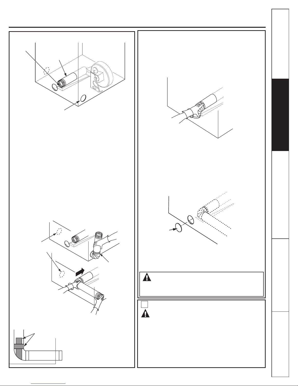
Mesures de sécurité
Sécheuse électrique
AJOUT D’UNE SECTION DE CONDUIT
TROU DE
FIXATION
SECTION «A»
ÉVACUATION
PAR LE CÔTÉ
GAUCHE OU
DROIT
Raccordez la section coupée du conduit (A) au boîtier du
ventilateur. Assurez-vous que la section du conduit est placée
vis-à-vis de la languette dans la base de l’appareil. À l’aide de la
vis que vous avez conservée, xez le conduit en place en vissant
la vis dans la languette de la base de la sécheuse.
AJOUT D’UN COUDE ET D’UNE SECTION DE
CONDUIT POUR L’ÉVACUATION PAR LE CÔTÉ
GAUCHE OU DROIT DE LA SÉCHEUSE
• Assemblez au préalable une section de conduit de 10 cm (4
po) à un coude de 10 cm (4 po). Scellez le joint à l’aide de ruban
gommé pour conduit.
• Insérez le conduit assemblé, le coude en premier, dans
l’ouverture latérale et raccordez le coude au conduit interne de
la sécheuse.
ATTENTION : faites attention à ne pas tirer ou
endommager les ls électriques à l’intérieur de la
sécheuse lorsque vous insérez le conduit.
www.electromenagersge.ca
ÉVACUATION PAR LE CÔTÉ GAUCHE
OU DROIT OU PAR LE DESSOUS DE LA
SÉCHEUSE
• Insérez le coude par l’ouverture à l’arrière de l’appareil, et
raccordez-le au conduit interne de la sécheuse.
• Appliquez du ruban gommé pour conduit sur le joint entre le
conduit interne de la sécheuse et le coude, comme illustré à la
page 11.
ATTENTION :
Les joints du conduit interne doivent être scellés au
moyen de ruban gommé pour conduit. Sinon, ils peuvent
se séparer et présenter un risque pour la sécurité.
INSTALLATION D’UNE PLAQUE
D’OBTURATION À L’ARRIÈRE DE
L’APPAREIL (ÉVACUATION PAR LES
CÔTÉS ET LE DESSOUS)
Directives d’installation Conseils de dépannage
Directives de fonctionnement
LE CONDUIT PEUT
ÊTRE INSTALLÉ DU
CÔTÉ GAUCHE OU
DROIT
RUBAN POUR
CONDUIT
• Appliquez du ruban gommé pour conduit, comme indiqué dans
l’illustration, sur le joint entre le conduit interne et le coude.
RUBAN POUR
DUCT
CONDUIT
TAPE
ATTENTION :
Les joints du conduit interne
doivent être scellés à l’aide
de ruban gommé. Sinon, ils
peuvent se séparer et présenter
un risque pour la sécurité.
PLAQUE
(ENSEMBLE
WE1M454)
Raccordez les coudes et les conduits en métal pour terminer
le système d’évacuation. Recouvrez l’ouverture à l’arrière à
l’aide d’une plaque d’obturation (ensemble WE1M454) que vous
pouvez vous procurer auprès de votre réparateur. Installez la
sécheuse à son emplacement nal.
AVERTISSEMENT – NE LAISSEZ JAMAIS
L’OUVERTURE NON RECOUVERTE À
L’ARRIÈRE DE L’APPAREIL. (ENSEMBLE WE1M454)
10
RÉPARATION
AVERTISSEMENT – IDENTIFIEZ TOUS
LES FILS AVANT DE LES DÉBRANCHER
POUR RÉPARER LES COMMANDES
DE L’APPAREIL. UNE ERREUR DE
BRANCHEMENT DES FILS PEUT
PROVOQUER UN FONCTIONNEMENT
INADÉQUAT ET DANGEREUX APRÈS LA
RÉPARATION OU L’INSTALLATION.
Service à la clientèle
11
Page 42

Sécheuse à gaz
AVANT DE COMMENCER
Veuillez lire attentivement toutes les directives qui suivent.
Mesures de sécurité
IMPORTANT -
utilisation éventuelle par l’inspecteur local.
Conservez ces directives pour une
IMPORTANT - Respectez tous les codes et
règlements en vigueur.
Note à l’installateur - Assurez-vous de laisser ces
directives au consommateur.
Note au consommateur - Gardez ces directives
avec votre guide d’utilisation et d’entretien pour une
consultation éventuelle.
Avant d’entreposer ou de jeter votre vieille sécheuse,
retirez la porte de l’appareil.
Directives d’installationConseils de dépannage
Le schéma de câblage et les renseignements concernant
la réparation se trouvent à l’intérieur du tableau de
commande.
Installez la sécheuse dans une pièce où la température
est supérieure à 10 °C (50 °F) pour assurer le bon
fonctionnement des commandes de l’appareil.
AVERTISSEMENT!
POUR VOTRE SÉCURITÉ :
N’utilisez qu’un conduit métallique rigide ou souple de 10
cm (4 po) de diamètre pour l’évacuation vers l’extérieur.
N’utilisez jamais un conduit en plastique ou fabriqué avec
tout autre matériau combustible facile à perforer.
Cet appareil doit être adéquatement mis à la terre et
installé conformément aux présentes directives.
N’installez pas ou n’entreposez pas l’appareil à un endroit
où il sera exposé à l’eau et (ou) aux intempéries.
L’air de cette sécheuse doit être évacué à l’extérieur.
Inspectez la sortie d’évacuation de la sécheuse et
redressez l’évent mural s’il est déformé.
Ne laissez pas les enfants grimper sur l’appareil ou à
l’intérieur de celui-ci. Il faut exercer une étroite surveillance
lorsque vous faites fonctionner cet appareil en présence
d’enfants.
REMARQUE : l’installation et la réparation de cette
sécheuse exigent des connaissances de base en
mécanique et en électricité.
OUTILS NÉCESSAIRES
Directives de fonctionnement
CLÉ À MOLETTE
DE 10 PO (2)
CLÉ À TUYAUX
DE 8 PO
Étape 1 Vériez votre installation de gaz (voir la section 2).
Étape 2 Préparez l’emplacement et l’évacuation pour l’installation
de la nouvelle sécheuse (voir la section 1).
Étape 3 Assurez-vous que le conduit d’évacuation externe en
place est propre (voir la section 1) et qu’il répond aux
exigences des directives d’installation qui suivent (voir la
section 6).
Étape 4 Enlevez les coussins d’expédition en mousse (voir la
section 1).
Étape 5 Amenez la sécheuse à l’endroit désiré.
Étape 6 Mettez votre sécheuse de niveau (voir la section 8).
Étape 7 Raccordez l’alimentation en gaz (voir la section 3) et
vériez si elle présente des fuites (voir la section 4).
Étape 8 Raccordez le système d’évacuation vers l’extérieur (voir la
section 7).
Service à la clientèle
12
PINCE À JOINT
COULISSANT
NIVEAU
TOURNEVIS À
EMBOUT PLAT
COMPOSANTES NÉCESSAIRES
COUDE EN MÉTAL DE
10 CM (4 PO) DE DIA.
PÂTE À JOINTS
RACCORD SOUPLE POUR
CONDUITE DE GAZ
Étape 9 Branchez le cordon d’alimentation (voir la section 5).
Étape 10 Vériez le bon fonctionnement de l’alimentation
Étape 11 Rangez le guide d’utilisation et d’entretien et les
Pour une installation dans un placard ou une alcôve, voir la
section 9.
Pour une installation dans une chambre à coucher ou une salle
de bain, voir la section 10.
Pour une installation dans une maison mobile ou préfabriquée,
voir la section 11.
CONDUIT MÉTALLIQUE DE 10 CM
(4 PO) DE DIA. (RECOMMANDÉ)
CONDUIT EN MÉTAL SOUPLE DE 10
CM (4 PO), DE DIA. (SI NÉCESSAIRE)
GANTS
électrique, du système d’alimentation en gaz et de
l’évacuation.
directives d’installation à un endroit où le propriétaire
pourra facilement les trouver.
2 COLLIERS
POUR CONDUIT
DE 10 CM (4 PO)
LUNETTES DE SÉCURITÉ
SOLUTION SAVONNEUSE
POUR DÉTECTION DES
FUITES
ÉVENT
RUBAN POUR
CONDUIT
Page 43

Mesures de sécurité
Sécheuse à gaz
www.electromenagersge.ca
Dégagements minimums pour les installations autres que dans une alcôve ou un placard.
Les dégagements minimums par rapport aux surfaces combustibles et pour l’ouverture d’aération sont les suivants : 0 cm (0 po)
des deux côtés et 2,5 cm (1 po) à l’arrière. Il faut prévoir un dégagement adéquat pour l’installation et la réparation.
1
PRÉPARATION POUR L’INSTALLATION
DE LA NOUVELLE SÉCHEUSE
RACCORD SOUPLE
POUR CONDUITE DE
GAZ APPROUVÉ PAR
CONDUITE
D’ALIMENTATION
EN GAZ
OUVERTURE DU
CONDUIT VERS
L’EXTÉRIEUR
LA CSA (AGA)
2
ALIMENTATION EN GAZ
Inclinez la sécheuse d’un
côté et enlevez les coussins
d’expédition en mousse en
les saisissant par les côtés
et en les cassant. Assurezvous d’enlever toutes les
particules de mousse
autour des pieds.
AVERTISSEMENT
RUBAN POUR
CONDUIT
CONDUIT EN
MÉTAL DE 10
CM (4 PO)
SUPPORT DE
PROTECTION
DU CONDUIT
D’ÉVACUATION
RUBAN POUR
CONDUIT
Tirez sur le support de protection du
conduit d’évacuation jusqu’à ce qu’il
bloque, puis laissez-le reposer sur le
sol. Ce support empêche l’appareil
d’être poussé trop près du mur,
ce qui pourrait écraser le conduit
d’évacuation à l’arrière.
CONSEIL : installez votre sécheuse avant d’installer votre
laveuse. Cela facilitera l’accès pour l’installation du conduit
d’évacuation de la sécheuse.
COUPURE DE L’ALIMENTATION EN GAZ
• L’installation doit être conforme aux codes locaux et avec le code
CAN/CGA-B149, Code d’Installation au Gaz Naturel.
• Cette sécheuse à gaz est pourvue d’une électrovanne et d’un
brûleur pour utilisation avec le gaz naturel seulement. À l’aide
de la trousse de conversion WE25M43, votre réparateur peut
transformer cette sécheuse en vue d’une alimentation au gaz
propane.
TOUTES LES CONVERSIONS DOIVENT ÊTRE EFFECTUÉES PAR
UNE PERSONNE FORMÉE ET QUALIFIÉE, ET CONFORMÉMENT À
TOUS, OU EN ABSENCE DE CODES LOCAUX, AU CODE CAN/CGAB149, CODE D’INSTALLATION AU GAZ NATUREL LES CODES ET
RÈGLEMENTS LOCAUX EN VIGUEUR.
• La sécheuse doit être isolée du système d’alimentation en gaz
pendant toute vérication de pression du système d’alimentation
en gaz lorsqu’on utilise une pression supérieure à 0,5 lb/po_ (3,4
kPa).
RACCORDEMENT À L’ALIMENTATION
EN GAZ DE LA SÉCHEUSE
Directives d’installation Conseils de dépannage
Directives de fonctionnement
FERMEZ LE
ROBINET
D’ALIMENTATION
EN GAZ.
DÉBRANCHEZ ET JETEZ L’ANCIEN
RACCORD SOUPLE ET L’ANCIEN
CONDUIT EN MÉTAL.
AVERTISSEMENT – NE RÉUTILISEZ
JAMAIS D’ANCIENS RACCORDS SOUPLES.
L’utilisation d’anciens raccords souples peut provoquer des
fuites et causer des blessures. Utilisez toujours des raccords
souples neufs lorsque vous installez des électroménagers à gaz.
ENLÈVEMENT DE LA CHARPIE DANS
L’OUVERTURE DU CONDUIT D’ÉVACUATION
MUR
OUVERTURE DU
CONDUIT DANS LA
RÉSIDENCE
ASSUREZ-VOUS QUE LE VOLET
DE L’ÉVENT S’OUVRE ET SE
FERME LIBREMENT
5 cm (2")
6,6 cm (2-5/8")
0,9 cm (3/8")
REMARQUE : Ajoutez à la dimension verticale la
distance entre le dessous de la sécheuse et le sol.
RACCORD FILETÉ MLE NPT DE 0,9 CM (3/8
PO) POUR L’ALIMENTATION EN GAZ
ALIMENTATION EN GAZ
• Un robinet à letage conique standard américain NPT de 0,3 cm
(1/8 po), accessible pour le raccordement d’un manomètre, doit être
installé en amont du raccord de la conduite de gaz à la sécheuse.
Si vous avez des questions concernant l’installation du robinet,
communiquez avec votre fournisseur de gaz.
• La conduite d’alimentation en gaz doit être constituée d’un tuyau
rigide de 1,2 cm (1/2 po) pourvu d’un robinet accessible à moins de
2 m (6 pi) de la sécheuse et se trouvant dans la même pièce que la
sécheuse.
• Appliquez de la pâte lubriante ou du ruban en Téon conçus pour le
gaz naturel ou propane.
• Vous devez utiliser avec cette sécheuse un connecteur certié
selon la norme ANSI Z21.24 / CSA 6.10.
• Branchez le raccord souple en métal à la sécheuse et à la conduite
d’alimentation en gaz.
• Ouvrez le robinet de la conduite.
13
Service à la clientèle
Page 44

Sécheuse à gaz
3
RÉTABLISSEMENT DE L’ALIMENTATION
EN GAZ
Raccord enregistré ANSI Z21.24 / CSA 6.10
Mesures de sécurité
FLARE
NOUVEAU RACCORD
SOUPLE EN MÉTAL POUR
L’ALIMENTATION EN GAZ
ADAPTATEUR
Directives d’installationConseils de dépannage
Note: Utiliser des nouveaux connecteurs seulement. Ne pas réutiliser
des connecteurs d’un autre appareil ou d’une ancienne installation.
Attention : Ne pas utiliser les écrous du connecteur exibles directement
sur les lets du tuyaux de la sécheuse et de la maison. Utiliser toujours
des adaptateurs appropriés et approuvés soit évasés - let à tuyaux
(are-NPT). Tenir les parties coniques des adaptateurs propres et libres
de toutes saletés, traces de graisse, d’huile ou de pâte d’étanchéité
pour lets.
NPT
COUDE
RACCORD
À FILETAGE
NPT DE 0,9
CM (3/8 PO)
ADAPTATEUR
BOUCHON DE
TUYAU À FILETAGE
NPT DE 0,3 CM
(1/8 PO) POUR
VÉRIFICATION DE LA
PRESSION DU GAZ
ROBINET
TUYAU D’AU
MOINS 1,2
CM (1/2 PO)
APPLIQUEZ DE LA PÂTE
LUBRIFIANTE SUR
TOUS LES FILETS MÂLES
Serrez tous les raccords à l’aide de deux clés à molette.
Ne serrez pas les raccords de façon excessive!
4
VÉRIFICATION DES FUITES
Directives de fonctionnement
APPLIQUEZ DE LA PÂTE LUBRIFIANTE
SUR L’ADAPTATEUR ET L’ENTRÉE DE LA
CONDUITE D’ALIMENTATION EN GAZ DE
LA SÉCHEUSE.
Serrez la
conduite souple
d’alimentation en
gaz à l’aide de deux
clés à molette.
Service à la clientèle
14
AVERTISSEMENT – N’UTILISEZ JAMAIS
UNE FLAMME NUE POUR VÉRIFIER LES
FUITES DE GAZ.
OUVREZ LE
ROBINET
Vériez tous les raccords à l’aide d’une solution savonneuse ou
l’équivalent pour voir s’ils présentent des fuites. Les solutions utilisées
pour la vérication des fuites ne doivent pas contenir d’ammoniaque
qui pourrait endommager les raccords ou les tuyaux en laiton. Si
vous constatez une fuite, fermez le robinet, resserrez le raccord et
effectuez à nouveau la vérication à l’aide de la solution savonneuse.
Page 45

Mesures de sécurité
Sécheuse à gaz
5
RACCORDEMENT ÉLECTRIQUE
AVERTISSEMENT – POUR RÉDUIRE LES
RISQUES D’INCENDIE, DE CHOCS ÉLECTRIQUES
ET DE BLESSURES :
N’UTILISEZ PAS DE RALLONGE ÉLECTRIQUE
OU DE FICHE D’ADAPTATION AVEC CET
APPAREIL.
La sécheuse doit être mise à la terre en conformité avec les
codes et règlements locaux en vigueur ou, en l’absence de
codes locaux, en conformité avec la norme C22.1 de l’ACNOR, à
la Partie 1 du Code canadien de l’électricité.
ALIMENTATION ÉLECTRIQUE
Cette sécheuse doit être branchée à un circuit adéquatement
mis à la terre de 120 V et 60 Hz, protégé par un disjoncteur ou
un fusible à retardement de 15 ou 20 ampères. Si l’alimentation
électrique ne répond pas à ces conditions, nous vous
recommandons de faire installer une prise de courant approuvée
par un électricien agréé.
AVERTISSEMENT – CETTE SÉCHEUSE
POSSÈDE UNE FICHE À TROIS BROCHES (MISE À LA
TERRE) POUR PLUS DE PROTECTION CONTRE LES
CHOCS ÉLECTRIQUES. ELLE DOIT ÊTRE BRANCHÉE
DIRECTEMENT DANS UNE PRISE DE COURANT
À TROIS ALVÉOLES, ADÉQUATEMENT MISE À LA
TERRE. L’INSTALLATION DOIT ÊTRE CONFORME
À LA NORME C22.1 DE L’ACNOR, À LA PARTIE 1
DU CODE CANADIEN DE L’ÉLECTRICITÉ OU AUX
CODES LOCAUX EN VIGUEUR. NE COUPEZ PAS OU
N’ENLEVEZ PAS LA BROCHE RONDE DE MISE À LA
TERRE DE CETTE FICHE.
AVANT DE BRANCHER LA
FICHE, ASSUREZ-VOUS QUE
LA MISE À LA TERRE EST
APPROPRIÉE.
SI LES CODES LOCAUX LE PERMETTENT, VOUS
POUVEZ BRANCHER UN FIL EXTERNE DE MISE
À LA TERRE (NON FOURNI), RÉPONDANT AUX EXIGENCES DES CODES
LOCAUX, ENTRE LA VIS VERTE DE MISE À LA TERRE À L’ARRIÈRE DE
LA SÉCHEUSE ET UNE CONDUITE MÉTALLIQUE D’EAU FROIDE MISE À LA
TERRE OU TOUT AUTRE SYSTÈME DE MISE À LA TERRE ÉTABLI.
www.electromenagersge.ca
6
ÉVACUATION DE L’AIR
AVERTISSEMENT – N’UTILISEZ QU’UN CONDUIT
EN MÉTAL DE 10 CM (4 PO) SEULEMENT. N’UTILISEZ PAS
UN CONDUIT PLUS LONG QUE CELUI INDIQUÉ DANS LE
TABLEAU DE LA LONGUEUR DES CONDUITS D’ÉVACUATION.
L’utilisation d’un conduit plus long que celui recommandé :
• Augmentera la durée du séchage et les frais d’énergie.
• Réduira la durée de vie utile de la sécheuse.
• Favorisera l’accumulation de charpie, créant un risque d’incendie.
VOUS AVEZ LA RESPONSABILITÉ d’installer le conduit d’évacuation
approprié. Les problèmes attribuables à une installation
incorrecte ne sont pas couverts par la garantie.
La longueur MAXIMALE PERMISE du conduit d’évacuation dépend
du type de conduit, du nombre de coudes, du type d’évent mural
employé et de toutes les conditions indiquées ci-dessous. Le tableau
qui suit indique les longueurs recommandées pour les conduits en
métal souple et rigide.
LONGUEUR DES CONDUITS D’ÉVACUATION
LONGUEUR MAXIMALE RECOMMANDÉE
Recommandé
Nombre de
coudes de 90º
Si vous utilisez un conduit souple en métal, reportez-vous à la page 18.
ÉVENT MURAL
• Installez un évent de manière à empêcher les retours d’air dans l’appareil ou
l’entrée d’oiseaux ou autres animaux.
• L’évent utilisé doit offrir une résistance minimale à l’air évacué et n’exiger qu’un
minimum d’entretien pour empêcher l’obstruction.
• N’installez jamais une grille à l’intérieur ou par-dessus le conduit d’évacuation,
augmentant le risque de feu. La grille pourrait provoquer l’accumulation de
charpie.
• L’évent mural doit être installé à au moins 30 cm (12 po) du sol ou de tout autre
obstacle lorsque l’ouverture est orientée vers le bas.
• Si vous utilisez un évent de toiture ou à volets, il doit présenter des caractéristiques
équivalentes à celles d’un évent mural à volet de 10 cm (4 po) en ce qui concerne
la résistance à la circulation d’air, la prévention des retours d’air et l’entretien exigé
pour éviter les obstructions.
LONGUEUR DE CONDUIT ENTRE LES COUDES
Pour un rendement optimum, prévoyez une longueur de conduit droit de 1,2 m (4 pi)
entre chaque coude, y compris entre le dernier coude et l’évent mural.
AUTRES TYPES DE COUDES
• Ne tenez pas compte d’un coude de 45° moins.
• 2 coudes de 45° équivalent à un coude de 90°.
• Chaque coude de plus de 45° équivaut à un coude de 90°.
SCELLEMENT DES JOINTS
• Tous les joints doivent être étanches pour éviter les fuites d’air. L’extrémité mâle
de chaque section de conduit doit être orientée en sens contraire par rapport à la
sécheuse.
• N’assemblez pas les sections de conduit avec des vis qui dépassent à l’intérieur du
conduit. Celles-ci risquent de créer des points d’accumulation de charpie.
• Assurez l’étanchéité à l’air et à l’humidité des conduits en recouvrant les joints de
ruban gommé pour conduit.
• Les longueurs horizontales de conduit doivent avoir une pente descendante vers
l’extérieur, à raison de 1,2 cm (1/2 po) par 30 cm (12 po).
ISOLATION
• Les conduits qui traversent une zone non chauffée ou qui se trouvent à proximité
d’un conduit de climatisation doivent être isolés an de réduire la condensation et
l’accumulation de charpie.
Rigide en
métal
27,4 m (90 pi)
18,3 m (60 pi)
13,7 m (45 pi)
10,7 m (35 pi)
7,6 m (25 pi)
LISTE DE CONTRÔLE DU SYSTÈME D’ÉVACUATION
Types d’évent
Souple en
métal
16,8 m (55 pi)
12,2 m (40 pi)
9,1 m (30 pi)
6,1 m (20 pi)
4,6 m (15 pi)
Utilisation pour les
conduits courts seulement
6,3 cm (2-1/2”)
Rigide en
métal
18,3 m (60 pi)
13,7 m (45 pi)
10,7 m (35 pi)
7,6 m (25 pi)
4,6 m (15 pi)
Souple en
métal
13,7 m (45 pi)
9,1 m (30 pi)
6,1 m (20 pi)
4,6 m (15 pi)
3,0 m (10 pi)
15
Directives d’installation Conseils de dépannage
Directives de fonctionnement
Service à la clientèle
Page 46

Sécheuse à gaz
7
RACCORDEMENT DU CONDUIT
D’ÉVACUATION
AVERTISSEMENT – POUR RÉDUIRE LES
RISQUES D’INCENDIE OU DE BLESSURES :
Mesures de sécurité
Directives d’installationConseils de dépannage
Directives de fonctionnement
• L’air de cette sécheuse doit être évacué à l’extérieur.
• N’utilisez qu’un conduit en métal seulement.
• Ne faites pas évacuer l’air de la sécheuse dans une
cheminée, dans un conduit d’évacuation des gaz brûlés,
sous un plancher (vide sanitaire) ou dans un grenier.
L’accumulation de charpie pourrait présenter un risque
d’incendie.
• Prévoyez un accès pour l’inspection et le nettoyage du
système d’évacuation, plus particulièrement au niveau des
coudes. Inspectez et nettoyez le système au moins une fois
par année.
• Ne faites jamais évacuer l’air de la sécheuse dans le conduit
d’évacuation d’une hotte de cuisine. Le mélange de charpie
et de graisse pourrait présenter un risque d’incendie.
• N’entravez pas la circulation de l’air qui entre dans la
sécheuse ou qui en est évacué.
NOUS VOUS RECOMMANDONS D’INSTALLER VOTRE SÉCHEUSE
AVANT VOTRE LAVEUSE AFIN DE FACILITER L’ACCÈS POUR LE
RACCORDEMENT DU CONDUIT D’ÉVACUATION.
CETTE SÉCHEUSE A ÉTÉ PRÉPARÉE EN VUE D’UNE ÉVACUATION PAR
L’ARRIÈRE. SI L’ESPACE EST LIMITÉ, SUIVEZ LES DIRECTIVES DE LA
SECTION 12 POUR EFFECTUER L’ÉVACUATION PAR L’UN DES CÔTÉS OU
LE DESSOUS DE L’APPAREIL.
ÉVACUATION STANDARD PAR L’ARRIÈRE
Pour installer le
conduit en ligne
droite, raccordez le
conduit d’évacuation
de la sécheuse à
l’évent extérieur à
l’aide de ruban pour
conduit ou d’un
collier.
Pour installer le conduit en
ligne droite, raccordez le
conduit d’évacuation de la
sécheuse à l’évent
extérieur à l’aide de ruban
pour conduit.
COUDE FORTEMENT
RECOMMANDÉ
CONFIGURATION
RECOMMANDÉE
POUR RÉDUIRE
MISE À NIVEAU
DE L’AVANT
VERS L’ARRIÈRE
COUDE
FORTEMENT
RECOMMANDÉ
REMARQUE : LES COUDES EMPÊCHENT L’ÉCRASEMENT ET
L’AFFAISSEMENT DU CONDUIT.
8
MISE À NIVEAU ET STABILISATION DE
AU MINIMUM
LE BLOCAGE
DU CONDUIT
D’ÉVACUATION
VOTRE SÉCHEUSE
Placez la sécheuse à proximité de son emplacement
nal, et réglez les 4 pieds de nivellement dans les 4
coins pour vous assurer que la sécheuse est à niveau
de la gauche vers la droite, et de l’avant vers l’arrière.
MISE À NIVEAU
DE L’AVANT
VERS L’ARRIÈRE
MISE À NIVEAU
DE LA GAUCHE
VERS LA DROITE
REMARQUE : NOUS VOUS RECOMMANDONS
FORTEMENT D’UTILISER UN CONDUIT
D’ÉVACUATION EN MÉTAL RIGIDE. CEPENDANT,
SI VOUS UTILISEZ UN CONDUIT SOUPLE,
COUPEZ-LE À LA LONGUEUR APPROPRIÉE ET
ÉVITEZ D’ÉCRASER LE CONDUIT À L’ARRIÈRE DE
LA SÉCHEUSE.
Service à la clientèle
16
4 PIEDS DE
NIVELLEMENT
Page 47

Mesures de sécurité
Sécheuse à gaz
UTILISATION D’UN CONDUIT SOUPLE EN MÉTAL ÉVACUATION
Si vous ne pouvez pas utiliser un conduit rigide entièrement en métal,
vous pouvez alors employer un conduit souple entièrement en métal,
mais cela aura pour effet de diminuer la longueur maximale de conduit
recommandée. Dans le cas d’installations spéciales, lorsqu’il est impossible
d’utiliser un conduit entièrement en métal, vous pouvez employer
un conduit de transition souple en métal homologué par UL pour les
sécheuses entre la sécheuse et le raccord au mur seulement. L’utilisation
de ce type de conduit allongera les durées de séchage.
Si vous devez utiliser un conduit de transition souple en métal, suivez les
directives ci-dessous.
• Utilisez la longueur la plus courte possible.
• Étirez le conduit à sa longueur maximale an d’éviter la formation de plis.
• Évitez d’écraser le conduit.
• Sortez le support de protection du conduit d’évacuation, comme
expliqué à l’étape 1.
• N’installez jamais un conduit de transition à l’intérieur du mur ou de la
sécheuse.
• Évitez de placer le conduit sur des objets tranchants.
• Le système d’évacuation doit être conforme aux codes du bâtiment locaux.
OUI
COUDE FORTEMENT
RECOMMANDÉ
UNE SÉCHEUSE PRODUIT DE LA CHARPIE COMBUSTIBLE.
DANS TOUS LES CAS, LA SÉCHEUSE DOIT ÊTRE
RACCORDÉE À UN CONDUIT D’ÉVACUATION
DONNANT SUR L’EXTÉRIEUR.
REMARQUE : L’AIR D’UNE SÉCHEUSE INSTALLÉE DANS
UNE MAISON MOBILE, UNE CHAMBRE À COUCHER, UNE
SALLE DE BAIN, UNE ALCÔVE OU UN PLACARD DOIT
ÊTRE ÉVACUÉ À L’EXTÉRIEUR.
INSTALLATION DANS UNE ALCÔVE OU
9
UN PLACARD
• Si votre sécheuse est conçue pour être installée dans une alcôve ou un
placard, cela sera indiqué sur une étiquette apposée sur le panneau
arrière de la sécheuse.
• L’air de la sécheuse DOIT être évacué à l’extérieur. Reportez-vous aux
points 3 et 4 de la section ÉVACUATION DE L’AIR.
• Les dégagements minimums entre la sécheuse et les murs adjacents
ou autres surfaces sont les suivants :
0 cm (0 po) de chaque côté
7,6 cm (3 po) à l’avant et à l’arrière
• Le dégagement vertical minimum entre le plancher et les armoires, le
plafond, etc., doit être de 109 cm (43 po) sans socle, et de 140 cm (55
po) avec socle.
• Les portes du placard doivent être pourvues de persiennes ou autre
dispositif d’aération équivalant à une ouverture de 387 cm² (60 po²)
répartie de façon égale. Si une sécheuse et une laveuse sont installées
dans le placard, les portes doivent être pourvues d’un dispositif
d’aération équivalant à une ouverture de 774 cm² (120 po²) répartie de
façon égale.
LORSQUE LE CONDUIT D’ÉVACUATION EST INSTALLÉ À
L’ARRIÈRE DE LA SÉCHEUSE, IL FAUT PRÉVOIR UN
DÉGAGEMENT MINIMUM DE 14 CM (5,5 PO) ENTRE
L’APPAREIL ET LE MUR.
www.electromenagersge.ca
Directives d’installation Conseils de dépannage
Directives de fonctionnement
N’UTILISEZ PAS
UNE LONGUEUR
EXCESSIVE
DE CONDUIT
COUDE FORTEMENT
RECOMMANDÉ
NON
NE PLACEZ PAS
LA SÉCHEUSE
SUR UN
CONDUIT
SOUPLE
N’ÉCRASEZ
PAS UN
CONDUIT
SOUPLE
CONTRE LE
MUR
10
INSTALLATION DANS UNE SALLE DE
BAIN OU UNE CHAMBRE À COUCHER
• L’air de la sécheuse DOIT être évacué à l’extérieur. Reportez-vous aux
points 3 et 4 de la section ÉVACUATION DE L’AIR.
• L’installation doit être conforme à tous les codes locaux en vigueur ou,
en l’absence de codes locaux, au CODE NATIONAL DE L’ÉLECTRICITÉ,
ANSI/NFPA n° 70.
11
INSTALLATION DANS UNE MAISON
MOBILE OU PRÉ-FABRIQUÉE
• L’installation doit être conforme aux codes d’installation dans les
maisons mobiles CAN/CSA série Z240 MH.
• L’air de la sécheuse DOIT être évacué à l’extérieur au moyen d’un évent
solidement xé à la structure de la maison mobile (reportez-vous au
points 6 de la section ÉVACUATION DE L’AIR).
• L’air de la sécheuse NE DOIT PAS être évacué sous une maison mobile
ou pré-fabriquée.
• Le conduit de l’évent DOIT être fabriqué en MÉTAL.
• Il FAUT utiliser l’ENSEMBLE 14-D346-33 pour xer solidement la
sécheuse à la structure de la maison.
• Le conduit d’évacuation NE DOIT PAS être raccordé à un autre conduit,
à un système de ventilation ou à une cheminée.
• N’utilisez pas de vis à métaux ou autres dispositifs similaires qui
pénètrent à l’intérieur du conduit d’évacuation.
• Prévoyez une ouverture et une zone libre d’au moins 161 cm² (25 po²)
pour l’arrivée du conduit d’évacuation vers l’extérieur dans la pièce de
la sécheuse.
Service à la clientèle
17
Page 48

Sécheuse à gaz
12
INSTALLATION DANS UN GARAGE
RÉSIDENTIEL
Une sécheuse installée dans un garage résidentiel doit être
élevée à 46 cm (18 pouces) au-dessus du sol.
13
Mesures de sécurité
Directives d’installationConseils de dépannage
ÉVACUATION PAR LE CÔTÉ GAUCHE
OU DROIT OU PAR LE DESSOUS DE LA
SÉCHEUSE
AVERTISSEMENT – PROTÉGEZ VOS
MAINS ET VOS BRAS DES BORDS TRANCHANTS
LORSQUE VOUS TRAVAILLEZ À L’INTÉRIEUR DE
L’APPAREIL. PORTEZ DES GANTS.
RETIREZ LA VIS
ET CONSERVEZ-LA
Défoncez et enlevez la débouchure inférieure, droite ou gauche.
Retirez la vis à l’intérieur du conduit d’évacuation de la sécheuse
et conservez-la. Tirez sur le conduit pour le sortir de la sécheuse.
Recouvrez les bords tranchants autour de l’entrée défonçable et
de l’ouverture d’évacuation avec du ruban gommé.
ENLEVEZ LA DÉBOUCHURE DÉSIRÉE
(UNE SEULEMENT)
TROU DE FIXATION
AJOUT D’UNE SECTION DE CONDUIT
TROU DE
FIXATION
SECTION «A»
ÉVACUATION
PAR LE CÔTÉ
GAUCHE OU
DROIT
Raccordez la section coupée du conduit (A) au boîtier du
ventilateur. Assurez-vous que la section du conduit est placée
vis-à-vis de la languette dans la base de l’appareil. À l’aide de la
vis que vous avez conservée, xez le conduit en place en vissant
la vis dans la languette de la base de la sécheuse.
AJOUT D’UN COUDE ET D’UNE SECTION DE
CONDUIT POUR L’ÉVACUATION PAR LE CÔTÉ
GAUCHE OU DROIT DE LA SÉCHEUSE
• Assemblez au préalable une section du conduit de 10 cm (4
po) à un coude de 10 cm (4 po). Scellez le joint à l’aide de ruban
gommé pour conduit.
• Insérez le conduit assemblé, le coude en premier, dans
l’ouverture latérale et raccordez le coude au conduit interne de
la sécheuse.
ATTENTION : faites attention à ne pas tirer ou
endommager les ls électriques à l’intérieur de la
sécheuse lorsque vous insérez le conduit.
Directives de fonctionnement
Coupez le conduit de la façon illustrée, et conservez la section A.
EMPLACEMENT DE LA LANGUETTE
REPLIEZ LA
LANGUETTE VERS
LE HAUT À 45°
Par l’ouverture arrière, repérez la languette au milieu de la base
de la sécheuse. Repliez la languette vers le haut à 45° environ à
l’aide d’un tournevis à embout plat.
Service à la clientèle
18
LE CONDUIT PEUT
ÊTRE INSTALLÉ DU
CÔTÉ GAUCHE OU
DROIT
RUBAN POUR
CONDUIT
• Appliquez du ruban gommé pour conduit, comme indiqué
dans l’illustration, sur le joint entre le conduit interne et le
coude.
RUBAN POUR
DUCT
CONDUIT
TAPE
ATTENTION :
Les joints du conduit interne
doivent être scellés à l’aide
de ruban gommé. Sinon, ils
peuvent se séparer et présenter
un risque pour la sécurité.
Page 49

Mesures de sécurité
Sécheuse à gaz
ÉVACUATION PAR LE CÔTÉ GAUCHE
OU DROIT OU PAR LE DESSOUS DE LA
SÉCHEUSE
• Insérez le coude par l’ouverture à l’arrière de l’appareil, et
raccordez-le au conduit interne de la sécheuse.
• Appliquez du ruban gommé pour conduit sur le joint entre le
conduit interne de la sécheuse et le coude, comme illustré à la
page 7.
ATTENTION :
Les joints du conduit interne doivent être scellés au
moyen de ruban gommé pour conduit. Sinon, ils peuvent
se séparer et présenter un risque pour la sécurité.
www.electromenagersge.ca
14
RÉPARATION
AVERTISSEMENT – IDENTIFIEZ TOUS
LES FILS AVANT DE LES DÉBRANCHER
POUR RÉPARER LES COMMANDES
DE L’APPAREIL. UNE ERREUR DE
BRANCHEMENT DES FILS PEUT
PROVOQUER UN FONCTIONNEMENT
INADÉQUAT ET DANGEREUX APRÈS LA
RÉPARATION OU L’INSTALLATION.
Pour connaître les numéros de téléphone pour obtenir des
pièces de rechange ou autres renseignements, consultez la
section du Service à la clientèle.
Directives d’installation Conseils de dépannage
Directives de fonctionnement
INSTALLATION D’UNE PLAQUE
D’OBTURATION À L’ARRIÈRE DE
L’APPAREIL (ÉVACUATION PAR LES
CÔTÉS ET LE DESSOUS)
PLAQUE
(ENSEMBLE
WE1M454)
Raccordez les coudes et les conduits en métal pour terminer
le système d’évacuation. Recouvrez l’ouverture à l’arrière à
l’aide d’une plaque d’obturation (ensemble WE1M454) que vous
pouvez vous procurer auprès de votre réparateur. Installez la
sécheuse à son emplacement nal.
AVERTISSEMENT – NE LAISSEZ JAMAIS
L’OUVERTURE NON RECOUVERTE À
L’ARRIÈRE DE L’APPAREIL. (ENSEMBLE WE1M454)
Service à la clientèle
19
Page 50

Inversion de l’ouverture de la porte
Outils nécessaires :
Mesures de sécurité
Directives d’installationConseils de dépannage
Tournevis Phillips
1. À l’aide d’un couteau à mastic ou d’un autre outil plat, retirez les capuchons
de vis en plastique situés sur le côté opposé des charnières. En gardant la
porte complètement ouverte, enlevez les vis du bas de chaque charnière.
Pour chaque charnière, insérez ces vis partiellement dans les trous du HAUT,
sur le côté opposé (où vous aurez retiré les capuchons de vis).
Appuyez fermement lors de l’insersion des vis dans les nouveaux trous.
2. Desserez partiellement les vis supérieures de chaque charnière. En
soutenant le HAUT de la porte avec une main et le bas avec l’autre main,
retirez la porte de la sécheuse en le soulevant et en la tirant vers l’extérieur.
Couteau à mastic
revêtu de ruban adhésif
Directives de fonctionnement
Service à la clientèle
20
3. Pivotez la porte du 180°. Insérez-la sur les vis du côté opposé et appuyez
vers le bas jusqu’à ce que les charnières reposent sur les vis supérieures
insérées à l’étape 1.
4. Enlevez les vis restantes du côté où la porte a été démonté. Insérez celles-ci
dans les trous du bas des charnières. Serrez les vis supérieures. Réinsérez
les capuchons de vis en plastique dans les trous où se trouvaient les vis
initialement.
Page 51

Mesures de sécurité
Le tableau de commande de votre sécheuse
Votre numéro de modèle est indiqué dans le haut, à l’intérieur de la porte.
Modèle MTMX100EM
3
Modèle HTMX100EM
1
www.electromenagersge.ca
Directives d’installation Conseils de dépannage
2
Directives de fonctionnement
3
Modèles GTMX100EM
GTMX100GM
3
Modèles GTMP200EM
GTMP200GM
1
2
1
2
Service à la clientèle
3
1
2
21
Page 52

Le tableau de commande de votre sécheuse
Votre numéro de modèle est indiqué dans le haut, à l’intérieur de la porte.
Modèles GTMP400EM
GTMP400GM
Mesures de sécurité
1
Modèles GTMN500EM
GTMN500GM
Directives d’installationConseils de dépannage
3
2
Directives de fonctionnement
3
1
2
Service à la clientèle
22
Page 53

Mesures de sécurité
Les options de votre sécheuse
IMPORTANT: nettoyez le ltre à charpie avant chaque utilisation.
Température
1
COTONS
PERMA PRESS
DÉLICATS
AIR FRAIS
sans chaleur
Programmes de séchage
2
Les programmes automatiques déterminent seuls le niveau de séchage du tissu. Pour obtenir des articles
légèrement humides, sélectionnez MOINS SEC. Sélectionnez PLUS SEC pour les sécher davantage.
COTONS
PERMA PRESS
DÉLICATS
SÉCHAGE MINUTÉ
Pour le coton.
Pour les tissus synthétiques, mixtes, délicats et articles étiquetés pour le pressage permanent.
(certains modèles) Pour tissus délicats, synthétiques et articles étiquetés pour le séchage par
culbutage à faible température.
Pour faire culbuter les articles sans chaleur. Réglez le temps de séchage avec MINUTÉ.
Pour les cotons et la plupart des draps. Pour la plupart des brassées, sélectionnez OPTIMUM
(certains modèles) ou l’option recommendée identiée avec un
Pour les articles infroissables, à pressage permanent et délicats, ainsi que les tricots.
Pour les articles délicats, les tissus exigeant un entretien particulier et les tricots.
Pour régler la durée de séchage désirée.
www.electromenagersge.ca
Directives d’installation Conseils de dépannage
*.
Directives de fonctionnement
HUMIDE
DÉFROISSEMENT
AIR FRAIS
Départ
3
Fermez la porte de la sécheuse. Sélectionnez
Pour obtenir des articles légèrement humides.
Pour éliminer les faux plis des articles qui sont secs ou légèrement humides.
Pour rafraîchir des vêtements, tissus, draps et oreillers qui sont déjà secs. À utiliser avec AIR
FRAIS SANS CHALEUR. Fournit 10 minutes de culbutage à faible température.
DÉPART pour lancer le cycle de séchage. Si vous ouvrez la porte
pendant le fonctionnement de la sécheuse, celle-ci s’arrêtera. Pour le recommencer, fermez la porte et
sélectionnez DÉPART de nouveau.
Logique des couleurs (sur certains modèles)
Sélectionnez le programme de TEMPERATURE
désiré. Associez la couleur en-dessous
des mots avec la couleur sur le bouton de
sélection des programmes.
Par exemple: sécher une brassée de
vêtements étiquetés pour le pressage
permanent.
Sélectionnez le programme de
1
TEMPERATURE désiré. Dans ce cas, le
programme serait PERMA PRESS MEDIUM
(qui est d’une certaine couleur).
Tournez le bouton de sélection jusqu’à
2
atteindre la même couleur que le
programme de TEMPERATURE que vous
avez choisi. Dans ce cas, l’option serait
PERMA PRESS.
Anti-froissage
Utilisez cette option pour minimiser
les froissements. La sécheuse
continue à culbuter sans chaleur pour
approximativement 15 minutes après que
les vêtements soient secs.
Cette option peut être utilisée uniquement
avec les programmes COTONS et PERMA
PRESS.
(sur certains modèles)
Si vous utilisez le bouton SIGNAL et
sélectionnez l’option ANTI-FROISSAGE, un
signal sonore se fera entendre à la n du
temps de séchage et à plusieurs reprises
pendant le cycle ANTI-FROISSAGE. Cela vous
rappelera de retirer les vêtements.
Si vous sélectionnez ARRÊT, la sécheuse
arrêtera quand la minuterie atteindra
l’indication ANTI-FROISSAGE.
Service à la clientèle
23
Page 54

Les options de votre sécheuse
Signal (sur certains modèles)
Mesures de sécurité
Directives d’installationConseils de dépannage
Un signal sonore se fera entendre vers la n
du temps de séchage pour vous rappeler de
retirer les vêtements. Sur certains modèles,
le niveau de son ne peut pas être ajusté.
Si vous avez sélectionné l’option ANTI-
FROISSAGE, le signal sonore se fera
entendre à la n du temps de séchage et
à plusieurs reprises pendant le cycle ANTIFROISSAGE. Cela vous rappelera de retirer
les vêtements.
NOTE :
Retirez les vêtements lorsque le signal
sonore se fait entendre an d’éviter les
plis.
Utilisez le SIGNAL surtout quand vous
séchez des tissus tels que des tricots et
ceux exigeant un pressage permanent.
Ces articles devraient être retirés an
d’éviter les plis.
Signal automatique (sur certains modèles)
À la n de chaque brassée, il y a
approximativement 15 minutes de
culbutage sans chaleur après que les
vêtements sont secs.
Un rappel sonore se fera entendre
occasionellement pendant cette
période pour vous rappeler de retirer les
vêtements.
Lampe de tambour (sur certains modèles)
Avant de remplacer l’ampoule, assurez-vous de débrancher le cordon d’alimentation
de la sécheuse ou de couper l’alimentation électrique en enlevant le fusible ou en
déclenchant le disjoncteur dans le panneau de distribution de la résidence. Penchezvous à l’intérieur de l’ouverture du tambour. Enlevez l’ampoule et remplacez la par une
ampoule identique.
Directives de fonctionnement
Service à la clientèle
24
Tambour en acier inoxydable (sur certains modèles)
Pour nettoyer les surfaces en acier inoxydable, utilisez un chiffon humide et un
détergent doux non abrasif convenant aux surfaces en acier inoxydable. Retirez les
résidus de produit nettoyant, puis séchez-les avec un chiffon propre.
L’acier inoxydable utilisé pour la fabrication du tambour de la sécheuse vous offre la
meilleure abilité possible dans une sécheuse GE. Si le tambour de la sécheuse venait
à être marqué ou rayé en cours d’usage normal, il ne rouillerait pas. Ses dommages
superciels n’affecteront pas sa durabilité ni son fonctionnement.
Page 55

Mesures de sécurité
Chargement et utilisation de la sécheuse
www.electromenagersge.ca
Pour le lavage, suivez toujours les directives indiquées sur les étiquettes d’entretien des tissus du fabricant.
Conseils pour le tri et le chargement
En règle générale, lorsque les vêtements sont
correctement triés pour le lavage, ils le sont aussi
pour le séchage. Triez les articles en fonction de leurs
dimensions. Par exemple, ne faites pas sécher un
drap avec des chaussettes ou d’autres petits articles.
N’ajoutez pas votre feuille d’assouplissant textile
lorsque la brassée a commencé à chauffer, car
elle risque de tacher vos vêtements. Les feuilles
d’assouplissant de tissus Bounce
été approuvées pour toutes les sécheuses GE si
MD
pour sécheuses ont
elles sont utilisées conformément aux directives du
fabricant.
Ne surchargez pas la sécheuse car c’est une perte
d’énergie et cela peut provoquer des faux plis.
Ne faites pas sécher les articles suivants dans la
sécheuse : articles en bre de verre, lainages, articles
recouverts de caoutchouc, plastiques, articles dotés
d’une garniture en plastique, articles remplis de
mousse de caoutchouc.
Entretien et nettoyage de la sécheuse
Extérieur: essuyez les produits de lessive renversés
et enlevez la poussière avec un linge humide. Le
ni et le tableau de commande de la sécheuse
peuvent être endommagés par certains produits de
traitement préliminaire et détachants. Appliquez ces
produits loin de la sécheuse. Vous pouvez ensuite
laver et faire sécher les vêtements normalement. Les
dommages causés à votre sécheuse par ces produits
ne sont pas couverts par votre garantie.
Filtre à charpie: nettoyez le ltre à charpie avant
chaque utilisation.
Tirez le ltre à charpie vers le
haut. Mouillez vos doigts et
enlever la charpie. Remettez
ensuite le ltre en place. Une
fois par année, faites nettoyer
la charpie accumulée dans la
sécheuse par un technicien
qualié.
Évent mural : Assurez-vous à l’aide d’un miroir que le
volet à l’intérieur de l’évent bouge facilement quand la
sécheuse fonctionne. Assurez-vous qu’il n’y a pas de
nid (d’oiseaux, d’insectes, etc.) à l’intérieur du conduit
d’évacuation ou de l’évent.
Acier inoxydable : Pour nettoyer les surfaces en acier
inoxydable, utilisez un chiffon humide et un détergent
doux non abrasif convenant aux surfaces en acier
inoxydable. Retirez les résidus de produit nettoyant, puis
séchez-les avec un chiffon propre.
L'acier inoxydable utilisé pour la fabrication du tambour
de la sécheuse vous offre la meilleure fiabilité possible
dans une sécheuse GE. Si le tambour de la sécheuse
venait à être marqué ou rayé en cours d'usage
normal, il ne rouillerait pas. Ces dommages superficiels
n'affecteront pas sa durabilité ni son fonctionnement.
Conduit d’évacuation : inspectez et nettoyez au
moins une fois par année le conduit d’évacuation de
la sécheuse an d’éviter qu’il ne se bloque. Lorsque
le conduit d’évacuation est partiellement obstrué,
cela a pour effet d’allonger la durée de séchage.
Suivez ces étapes :
Coupez l’alimentation électrique en débranchant
1
le cordon d’alimentation de la prise murale.
Débranchez le conduit d’évacuation de la
2
sécheuse.
Passez le tuyau de l’aspirateur dans le conduit
3
d’évacuation, et rebranchez le conduit
d’évacuation à la sécheuse.
Directives d’installation Conseils de dépannage
Directives de fonctionnement
Service à la clientèle
25
Page 56

Avant d’appeler un réparateur…
Conseils de dépannage
Économisez du temps et de l’argent! Consultez d’abord
les tableaux qui suivent ou visitez le site GEAppliances.ca.
Vous pourriez éviter un appel de service.
Mesures de sécurité
PROBLÈME Causes Possibles Correctifs
La sécheuse ne se met
pas en marche
La sécheuse ne
chauffe pas
Directives d’installationConseils de dépannage
La sécheuse est
bruyante ou vibre
Taches de graisse sur les
vêtements
Directives de fonctionnement
La sécheuse est débranchée
Un fusible est grillé ou un
disjoncteur est déclenché
Un fusible est grillé ou un disjoncteur
est déclenché ; le tambour peut tourner
mais il n’y a pas de chaleur
L’alimentation en gaz est coupée
Un peu de vibration ou de bruit
est normal. Il est possible que la
sécheuse ne repose pas solidement
sur le plancher
Utilisation inadéquate
d’assouplissant
Séchage d’articles sales avec des
articles propres
Nettoyage insufsant des
vêtements
• Assurez-vous que la che de la sécheuse est complètement
insérée dans la prise de courant.
• Vériez le fusible ou le disjoncteur dans le tableau de
distribution, et remplacez le fusible ou réenclenchez le
disjoncteur. REMARQUE : les sécheuses électriques sont
protégées par deux fusibles ou disjoncteurs.
• Vériez les fusibles et les disjoncteurs dans le tableau de
distribution de la résidence, et remplacez les deux fusibles
ou réenclenchez les deux disjoncteurs. Il est possible que
le tambour tourne si un seul fusible est grillé ou si un seul
disjoncteur est déclenché.
• Assurez-vous que le robinet d’arrêt de la sécheuse et le robinet
d’arrêt principal sont complètement ouverts.
• Installez la sécheuse sur un plancher uniforme ou réglez les
pieds de nivellement an que la sécheuse soit de niveau.
• Suivez les directives inscrites sur l’emballage de l’assouplissant.
• Ne faites sécher que des articles propres dans votre sécheuse.
Les articles sales peuvent tacher les articles propres et la
sécheuse.
• Parfois, les taches qui sont invisibles lorsque les articles sont
mouillés apparaissent après le séchage. Utilisez le procédé de
lavage approprié avant de sécher les articles.
Charpie sur les vêtements
Électricité statique
Service à la clientèle
26
Filtre à charpie plein
Tri incorrect
Charpie attirée par l’électricité
statique
Surcharge
Papier, papier-mouchoir, etc.,
oubliés dans les poches
Aucun produit assouplissant
utilisé
Séchage excessif
Les mélanges, les tissus
synthétiques et sans repassage
peuvent causer de l’électricité
statique
• Nettoyez le ltre à charpie avant chaque utilisation.
• Séparez les tissus qui produisent de la charpie de ceux qui la
recueillent.
• Voir les suggestions données à la section ÉLECTRICITÉ
STATIQUE ci-dessous.
• Divisez les grosses brassées en brassées plus petites.
• Videz toutes les poches avant de laver les vêtements.
• Utilisez un produit assouplissant.
• Les feuilles d’assouplissant de tissus Bounce
ont été approuvées pour toutes les sécheuses GE si elles sont
utilisées conformément aux instructions du fabricant.
MD
pour sécheuse
• Utilisez un produit assouplissant.
• Utilisez les options –SEC ou HUMIDE.
• Utilisez un produit assouplissant.
Page 57

Mesures de sécurité
Avant d’appeler un réparateur…
PROBLÈME Causes Possibles Correctifs
Durées de séchage
irrégulières
Les vêtements prennent
trop de temps à sécher
Type de chaleur
Type de brassée et conditions de
séchage
Conduit d’évacuation inadéquat ou
obstrué
Tri incorrect
Grosses brassées d’articles épais
(comme des serviettes de plage)
Commandes mal réglées
Filtre à charpie plein
Fusibles grillés ou disjoncteurs
déclenchés
Surcharge/brassées mixtes
• Les durées de séchage varient selon le type d’énergie utilisé.
Si vous avez dernièrement remplacé un modèle électrique par
une sécheuse à gaz (naturel ou propane) ou l’inverse, il est
possible que les durées de séchage soient différentes.
• La grosseur de la brassée, les types de tissus, le degré
d’humidité des vêtements, ainsi que la longueur et l’état du
système d’évacuation ont une inuence sur les durées de
séchage.
• Vériez les directives d’installation pour vous assurer que
l’évacuation de la sécheuse est adéquate.
• Assurez-vous que le conduit est propre, qu’il n’est pas plié ni
obstrué.
• Vériez si le volet de l’évent mural bouge librement.
• Séparer les articles épais des articles légers (en général,
lorsque la brassée est bien triée pour le lavage, elle l’est aussi
pour le séchage).
• Les gros articles épais retiennent davantage d’humidité et
prennent plus de temps à sécher. Faites sécher de plus petites
brassées pour accélérer le séchage.
• Réglez les commandes en fonction de la brassée que vous
faites sécher.
• Nettoyez le ltre à charpie avant chaque utilisation.
• Remplacez les fusibles ou réenclenchez les disjoncteurs.
Comme la plupart des sécheuses nécessitent deux fusibles/
disjoncteurs, assurez-vous que les deux sont en bon état.
• Ne mettez dans la sécheuse qu’une brassée de linge à la fois.
www.electromenagersge.ca
Directives d’installation Conseils de dépannage
Directives de fonctionnement
Les vêtements sont
froissés
Les vêtements
rétrécissent
Brassées trop petite
Séchage excessif
Articles laissés dans la sécheuse
après la n du programme
Surcharge
Certains tissus rétrécissent au
lavage. D’autres peuvent être
lavés en toute sécurité, mais
rétrécissent au séchage
• Lorsque vous ne faites sécher qu’un ou deux articles, ajoutez
quelques vêtements pour assurer un culbutage adéquat.
• Choisissez une durée de séchage plus courte.
• Retirez les vêtements de la sécheuse lorsqu’ils sont encore
légèrement humides. Choisissez l’option – SEC ou HUMIDE.
• Retirez les articles de la sécheuse lorsque le programme
est terminé. Pliez-les ou suspendez-les immédiatement, ou
choisissez l’option CULBUTAGE +.
• Divisez les grosses brassées en brassées plus petites.
• Pour éviter tout rétrécissement, suivez à la lettre les directives
sur l’étiquette d’entretien des vêtements.
• Certains articles peuvent retrouver leur forme d’origine après le
séchage grâce à un pressage.
• Lorsque vous ne savez pas si un article rétrécit ou non, ne le
lavez pas ou ne le faites pas sécher à la machine.
Service à la clientèle
27
Page 58

Notes
Mesures de sécurité
Directives d’installation
Directives de fonctionnement
Conseils de dépannage
Service à la clientèle
28
Page 59

Garantie de votre sécheuse GE (pour les clients au Canada seulement)
Mesures de sécurité
Toutes les réparations sous garantie seront effectuées par
nos centres de réparation ou par un technicien Customer
CareMD autorisé. Pour prendre un rendez-vous, composez le
1-800-561-3344 24 heures sur 24, 7 jours par semaine.
Période :
Un an
À compter de la date
d’achat d’origine
Nous remplacerons :
Toute pièce de la sécheuse qui se révèle défectueuse en raison d’un vice de matières ou de
fabrication. Pendant cette garantie complète d’un an, Mabe assumera également tous les
frais de main-d’œuvre et les frais connexes de service pour remplacer la pièce défectueuse.
Ce qui n’est pas couvert :
Toute visite à votre domicile pour vous expliquer
le fonctionnement de l’appareil.
Une installation, une livraison ou un entretien
inadéquats.
Toute défectuosité du produit lorsqu’il est utilisé
de façon abusive, à des ns commerciales ou
à toute autre n que celle pour laquelle il a été
conçu.
Agrafez votre facture ici. Pour
bénécier de réparation sous
garantie, il est nécessaire de
présenter une preuve de la date
d’achat d’origine.
Tout dommage du produit attribuable à un
accident, un incendie, une innondation ou un cas
de force majeure.
Tout dommage direct ou indirect causé par une
défectuosité éventuelle de l’appareil.
Tout dommage causé après la livraison.
Directives d’installation Conseils de dépannage
Directives de fonctionnement
Le remplacement des fusibles ou le
réenclenchement des disjoncteurs du panneau
de distribution.
La présente garantie est accordée à l’acheteur d’origine et à tout propriétaire subséquent du produit acheté pour
utilisation domestique au Canada. Le service de réparation à domicile sous garantie est offert dans les régions où
Mabe est raisonnablement en mesure de l’offrir.
Garant : Mabe Canada Inc., Burlington, ON L7R 5B6
Service à la clientèle
29
Page 60

Service à la clientèle
Site Web des électroménagers GE
Vous avez une question ou vous avez besoin d’aide pour votre appareil électroménager? Contactez-nous par
Internet via le site electromenagersge.ca 24 heures par jour, tous les jours de l’année.
Service de réparation
Le service de réparation Mabe est tout près de chez vous.
Composez le 1.800.561.3344.
1.800.561.3344 ou electromenagersge.ca
electromenagersge.ca
Studio de conception réaliste
Sur demande, GE peut fournir une brochure sur l’aménagement d’une cuisine pour les personnes à mobilité
réduite.
Au Canada
Bureau 310, 1 Factory Lane
Moncton, N.B. E1C 9M3
Prolongation de garantie
Achetez un contrat d’entretien Mabe et bénéciez d’un rabais substantiel pendant que votre garantie est
encore en vigueur. Ainsi le service après-vente Mabe sera toujours là après expiration de la garantie.
Visitez notre site Web ou appelez-nous au 1.888.261.2133.
, écrivez à l’adresse suivante : Directeur, Relations avec les consommateurs, Mabe Canada Inc.
1.888.261.2133 ou electromenagersge.ca
Pièces et accessoires
Les gens qui désirent réparer eux-mêmes leurs électroménagers peuvent recevoir des pièces et des
accessoires directement à la maison (cartes VISA, MasterCard et Discover acceptées). Veuillez composer le
1.800.661.1616 ou communiquez avec la succursale Mabe de votre région.
Les directives données dans le présent manuel peuvent être effectuées par n’importe quel utilisateur. Les
autres réparations doivent être généralement conées à un technicien qualié. Il faut faire preuve de
prudence car une réparation inadéquate peut affecter le fonctionnement sécuritaire de l’appareil.
Contactez-nous
Si vous n’êtes pas satisfait du service après-vente dont vous avez bénécié :
PREMIÈREMENT, communiquez avec les gens qui ont réparé votre appareil.
ENSUITE, si vous n’êtes toujours pas satisfait, écrivez à l’adresse suivante, en fournissant tous les détails, y compris
votre numéro de téléphone :
Directeur, Relations avec les consommateurs, Mabe Canada Inc.
Bureau 310, 1 Factory Lane
Moncton, N.B. E1C 9M3
Dans toute correspondance, veuillez fournir tous les détails, comme les numéros de modèle et de série, la date
d’achat, ainsi que votre numéro de téléphone.
Inscrivez votre appareil électroménager
1.800.661.1616 ou electromenagersge.ca
electromenagersge.ca
electromenagersge.ca
Inscrivez votre appareil électroménager en direct, aussitôt que possible. Cela améliorera nos
communications et notre service après-vente. Vous pouvez également nous envoyer par la poste le
formulaire d’inscription joint à votre documentation.
30
Imprimé au Mexique
 Loading...