

Page 1
ge.com
Refrigerators
Top-Freezer
197D7733P001 49-60505-1 07-07 JR
Safety Instructions . . . . . . . . . . .2–4
Operating Instructions
Automatic Icemaker . . . . . . . . . . . .9
Controls . . . . . . . . . . . . . . . . . . . . . .5
Crispers and Pans . . . . . . . . . . . .7, 8
Shelves and Bins . . . . . . . . . . . . . . .6
Care and Cleaning
Care and Cleaning . . . . . . . . . .10, 11
Replacing the Light Bulb . . . . . . .11
Installation Instructions
Icemaker Installation . . . . . . . .13–16
Preparing to Install
the Refrigerator . . . . . . . . . . . . . . .12
Reversing the Door Swing . . . .21–25
Water Line Installation . . . . . .17–21
Troubleshooting Tips . . . . . . .26–29
Normal Operating Sounds . . . . . .26
Consumer Support
Consumer Support . . . . .Back Cover
Product Registration
for Canadian Customers . . . . .33, 34
Product Registration
for U.S. Customers . . . . . . . . .31, 32
Warranty for
Canadian Customers . . . . . . . . . . .35
Warranty for U.S. Customers . . . . .36
Réfrigérateurs
Congélateur supérieur
Refrigeradores
Congelador superior
Models GTH21 and GTL21
Manuel d’utilisation
et d’installation
Owner’s Manual and
Installation Instructions
Manual del propietario
e instalación
La section française commence à la page 37
La sección en español empieza en la página 73
Note to Installer – Be sure to leave
these instructions with the Consumer.
Note to Consumer – Keep these
instructions for future reference.
Note à l’installateur – Assurez-vous
de laisser ces instructions au
consommateur.
Note au consommateur –
Conservez ces instructions pour
référence future.
Nota al instalador – Asegúrese
de dejar estas instrucciones con el
consumidor.
Nota al consumidor – Conserve
estas instrucciones para referencia futura.
Write the model and serial numbers here:
Model # __________________________
Serial # __________________________
Find these numbers on the gray label
on the left side, near the top of the
refrigerator compartment.
Page 2

IMPORTANT SAFETY INFORMATION.
READ ALL INSTRUCTIONS BEFORE USING.
WARNING!
Use this appliance only for its intended purpose as described in this Owner’s Manual.
SAFETY PRECAUTIONS
When using electrical appliances, basic safety precautions should be followed, including the following:
■
■ This refrigerator must be properly installed
and located in accordance with the Installation
Instructions before it is used.
■
■ Do not allow children to climb, stand or hang
on the shelves in the refrigerator. They could
damage the refrigerator and seriously injure
themselves.
■
■ Do not touch the cold surfaces in the freezer
compartment when hands are damp or wet.
Skin may stick to these extremely cold surfaces.
■
■ Do not store or use gasoline or other flammable
vapors and liquids in the vicinity of this or any
other appliance.
■
■ In refrigerators with automatic icemakers,
avoid contact with the moving parts of the
ejector mechanism, or with the heating element
located on the bottom of the icemaker. Do not
place fingers or hands on the automatic
icemaking mechanism while the refrigerator
is plugged in.
■
■ Keep fingers out of the “pinch point” areas;
clearances between the doors and between the
doors and cabinet are necessarily small. Be careful
closing doors when children are in the area.
■
■ Unplug the refrigerator before cleaning and
making repairs.
NOTE: We strongly recommend that any servicing be
performed by a qualified individual.
■
■ Setting either or both controls (some models only
have one control) to the 1 (off) position does not
remove power to the light circuit.
■
■ Do not refreeze frozen foods which have
thawed completely.
Consumer Support Troubleshooting Tips
Operating Instructions Safety InstructionsInstallation Instructions
2
Page 3
3
Consumer SupportTroubleshooting TipsOperating InstructionsSafety Instructions Installation Instructions
ge.com
USE OF EXTENSION CORDS
Because of potential safety hazards under certain conditions, we strongly recommend against the
use of an extension cord.
However, if you must use an extension cord, it is absolutely necessary that it be a UL-listed (in the United
States) or a CSA-listed (in Canada), 3-wire grounding type appliance extension cord having a grounding
type plug and outlet and that the electrical rating of the cord be 15 amperes (minimum) and 120 volts.
DANGER! RISK OF CHILD ENTRAPMENT
PROPER DISPOSAL OF THE REFRIGERATOR
Child entrapment and suffocation are not
problems of the past. Junked or abandoned
refrigerators are still dangerous…even if they will
sit for “just a few days.” If you are getting rid of
your old refrigerator, please follow the instructions
below to help prevent accidents.
Before You Throw Away Your Old
Refrigerator or Freezer:
■ Take off the doors.
■ Leave the shelves in place so that children
may not easily climb inside.
Refrigerants
All refrigeration products contain refrigerants,
which under federal law must be removed prior
to product disposal. If you are getting rid of an
old refrigeration product, check with the company
handling the disposal about what to do.
Page 4
4
Consumer Support Troubleshooting Tips
Operating Instructions Safety InstructionsInstallation Instructions
IMPORTANT SAFETY INFORMATION.
READ ALL INSTRUCTIONS BEFORE USING.
WARNING!
HOW TO CONNECT ELECTRICITY
Do not, under any circumstances, cut or remove the third (ground) prong from the power cord.
For personal safety, this appliance must be properly grounded.
The power cord of this appliance is equipped with
a 3-prong (grounding) plug which mates with a
standard 3-prong (grounding) wall outlet to
minimize the possibility of electric shock hazard
from this appliance.
Have the wall outlet and circuit checked by a
qualified electrician to make sure the outlet is
properly grounded.
Where a standard 2-prong wall outlet is
encountered, it is your personal responsibility and
obligation to have it replaced with a properly
grounded 3-prong wall outlet.
The refrigerator should always be plugged into its
own individual electrical outlet which has a voltage
rating that matches the rating plate.
This provides the best performance and also
prevents overloading house wiring circuits which
could cause a fire hazard from overheated wires.
Never unplug your refrigerator by pulling on the
power cord. Always grip plug firmly and pull
straight out from the outlet.
Repair or replace immediately all power cords that
have become frayed or otherwise damaged. Do not
use a cord that shows cracks or abrasion damage
along its length or at either end.
When moving the refrigerator away from the
wall, be careful not to roll over or damage the
power cord.
READ AND FOLLOW THIS SAFETY INFORMATION CAREFULLY.
SAVE THESE INSTRUCTIONS
Page 5
Consumer SupportTroubleshooting TipsOperating Instructions
Safety Instructions
Installation Instructions
5
About the controls on the refrigerator. ge.com
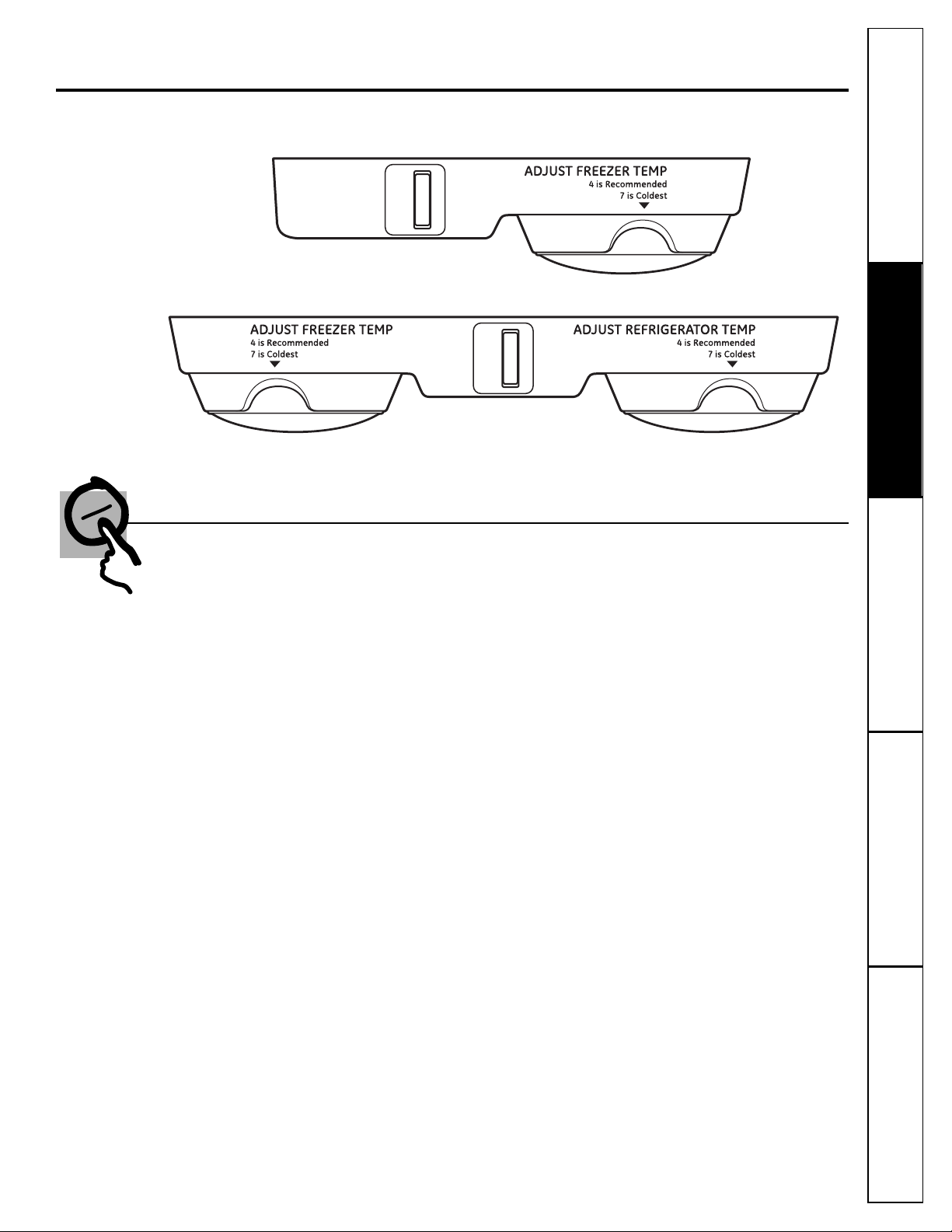
Control Settings
Initially, set the control(s) at 4. Allow 24 hours for the temperature to stabilize.
Several adjustments may be required. Adjust the control(s) one increment at a time and
allow 12 hours after each adjustment for the refrigerator to reach the temperature you
have set.
Setting the refrigerator control to 1 stops cooling in both the freezer and refrigerator
compartments but does not shut off electrical power to the refrigerator. The freezer
control (on some models) has no effect on electrical power to the refrigerator.
Control settings will vary based on personal preferences, usage and operating conditions,
and may require more than one adjustment. Factors that affect temperature include the
amount of food in the refrigerator or freezer, the frequency of door opening and the
temperature of food when it is placed in the refrigerator.
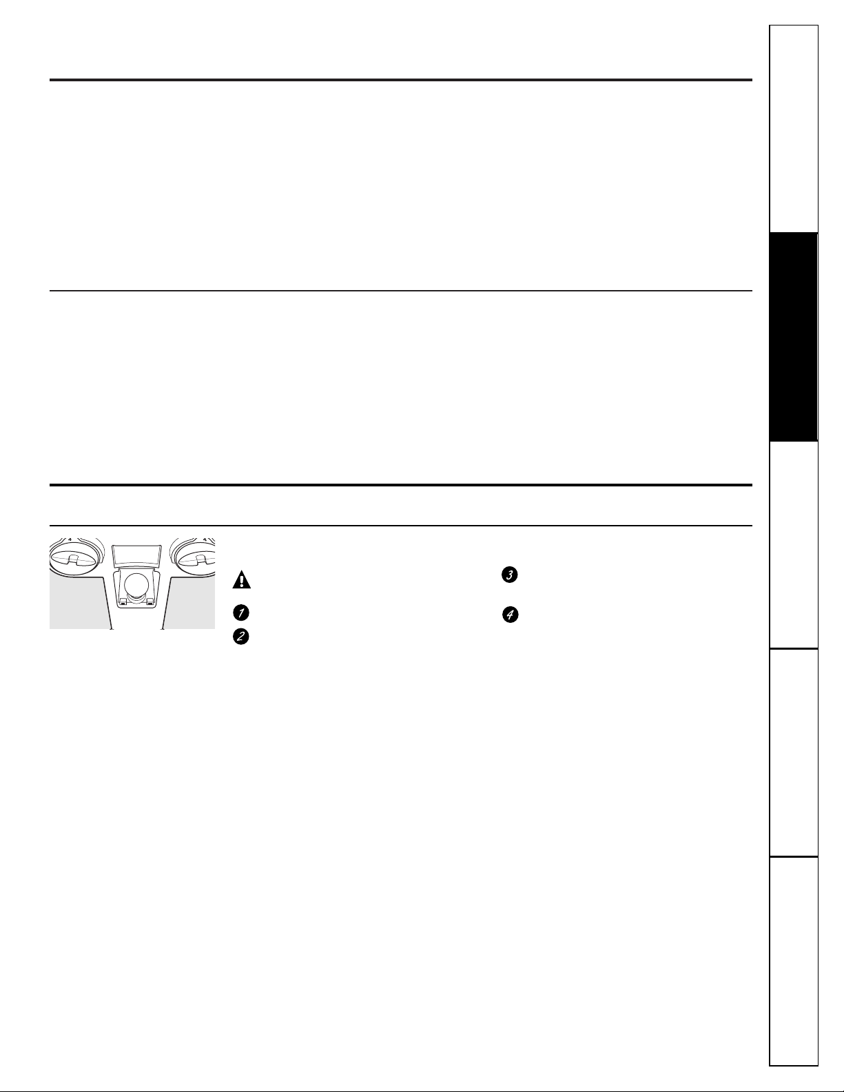
The controls on your refrigerator will look like one of the following:
4
44
Page 6
6
Consumer Support Troubleshooting Tips
Operating Instructions Safety InstructionsInstallation Instructions
About the shelves and bins.
Not all features are on all models.
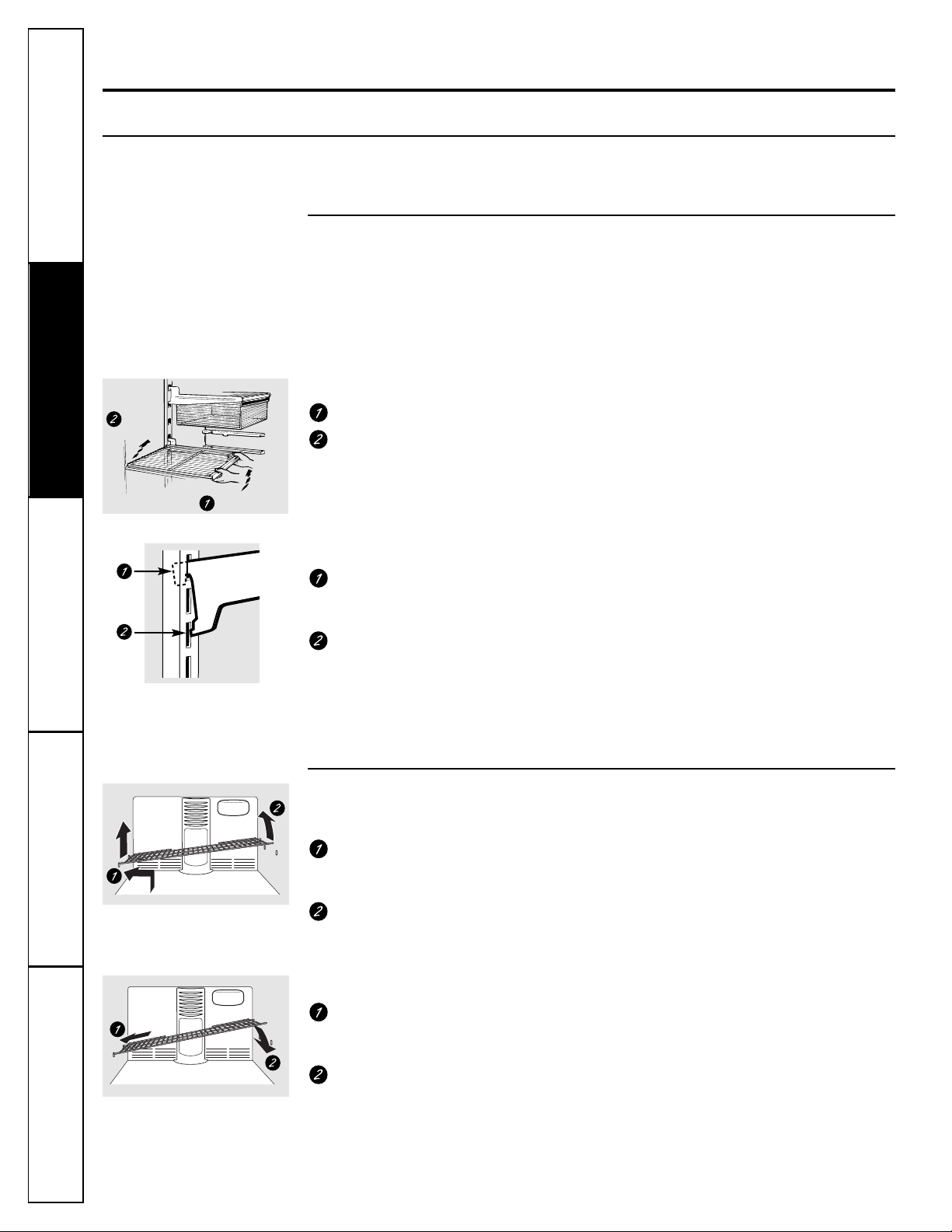
Rearranging the Shelves
Shelves in the refrigerator and freezer compartments are adjustable.
Refrigerator Compartment
Half-Width Shelves
One end of the shelf rests on a
molded side-wall support; a bracket
on the other end hooks into a track
on the rear cabinet wall.
To remove:
Tilt the shelf up at the front.
Lift the support off and out of the track.
To replace:
While tilting the shelf up, insert the top
hook at the back of the shelf in a slot
on the track.
Lower the front of the shelf until the
bottom of the shelf locks into place.
NOTE: The shelf to the right of the track is
designed to hook into the right-hand slot; the
shelf to the left is designed to hook into the
left-hand slot.
Freezer Compartment
To remove:
Lift up the left side of the shelf and
slide it left into the center of the shelf
supports.
Rotate the right side of the shelf up and
out of the shelf supports.
To replace:
Holding the shelf diagonally, insert the
left end of the shelf into the center of
the shelf supports on the side wall.
Insert the right end of the shelf into
the shelf supports on the side wall.
Rest each end of the shelf on the
bottom of the shelf supports.
Lift up
and out
Tilt up
Page 7
7
Consumer SupportTroubleshooting TipsOperating Instructions
Safety Instructions
Installation Instructions
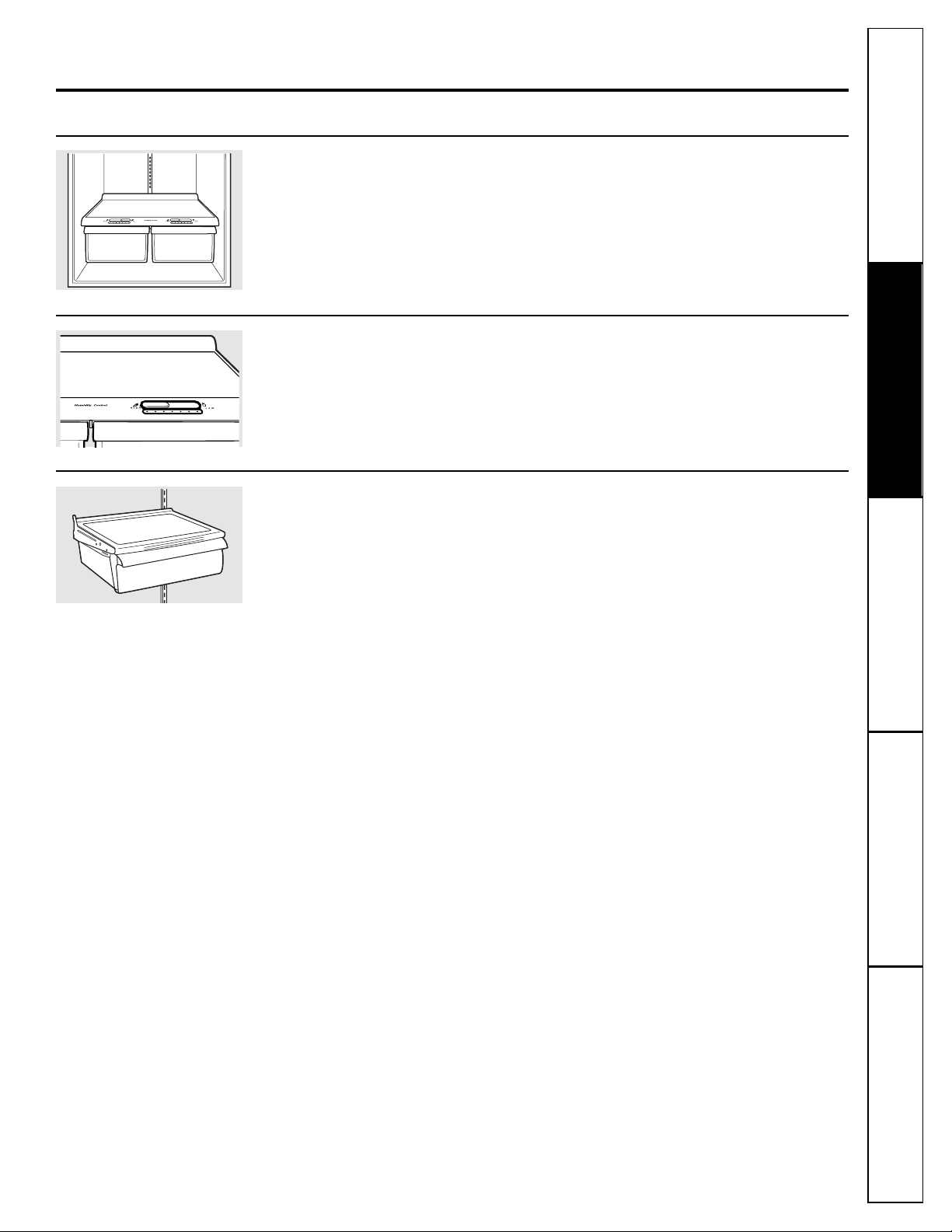
Adjustable Humidity Crisper
Slide the control all the way to the
HIGH setting to provide high humidity
recommended for most vegetables.
Slide the control all the way to the LOW
setting to provide lower humidity levels
recommended for most fruits.
Snack Pan
This pan can be moved to the most useful
location for your family’s needs.
To remove, slide the pan out to the stop
position, lift the pan up and past the stop
position, and lift out.
About the crispers and pans. ge.com
Not all features are on all models.
Fruit and Vegetable Crispers
Excess water that may accumulate in the
bottom of the drawers or under the drawers
should be wiped dry.
Page 8
8
Consumer Support Troubleshooting Tips
Operating Instructions Safety InstructionsInstallation Instructions
Removing the glass cover
Removing the frame
About crisper removal.
Not all features are on all models.
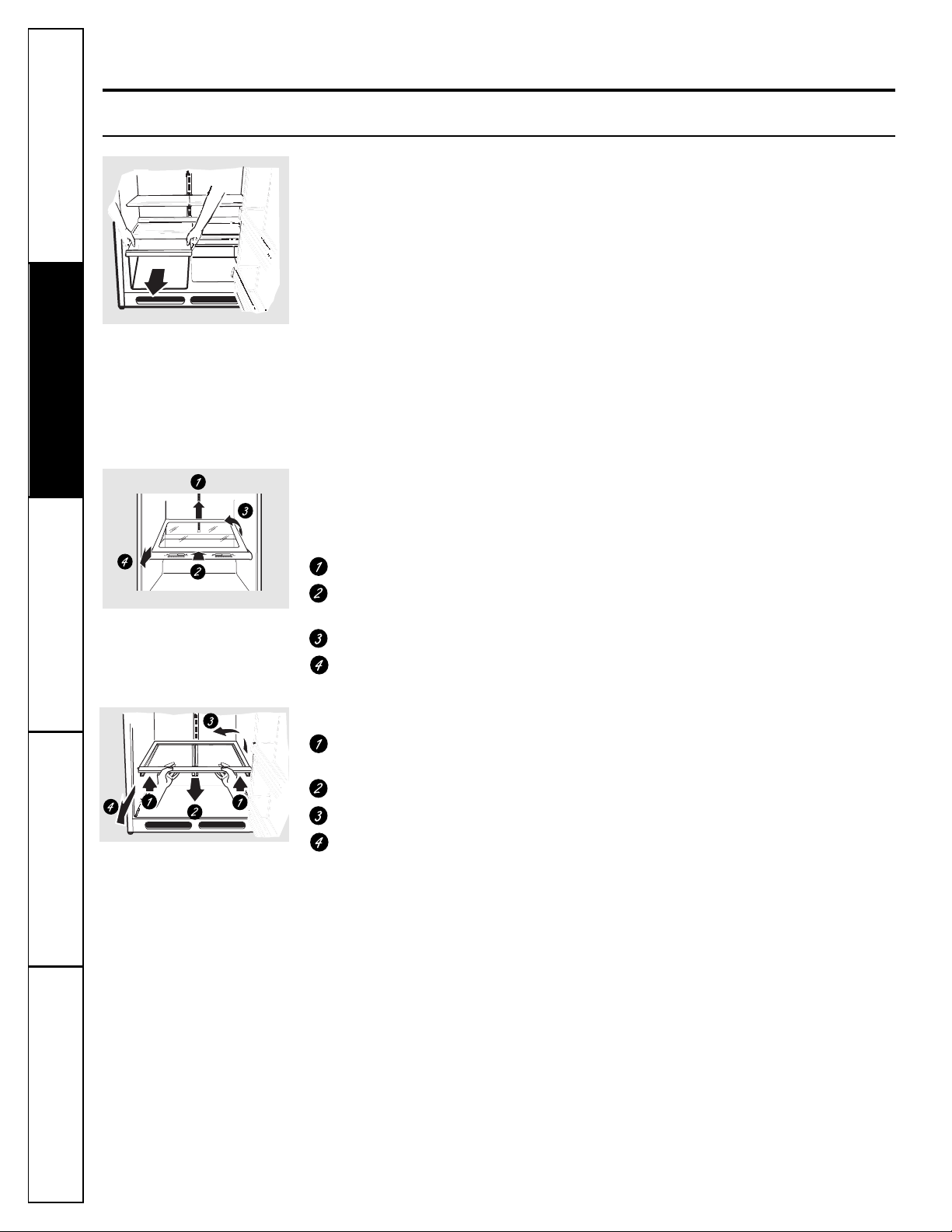
Crisper Removal
Unload the bottom shelf before attempting to
remove the storage drawers.
To Remove:
Lift the drawers up slightly while pulling
them past the stop location.
If the door prevents you from taking out
the drawers, first try to remove the door
bins. If this does not offer enough
clearance, the refrigerator will need to
be rolled forward until the door opens
enough to slide the drawers out. In some
cases, when you roll the refrigerator out,
you will need to move the refrigerator
to the left or right as you roll it out.
To remove the glass cover:
Remove the glass, then the frame. When
replacing the glass, push the front edge
firmly into the frame.
Push up the glass cover at the rear.
Slide the glass cover backwards until the
front edge comes out of the frame.
Rotate the side of the glass cover up.
Remove the glass cover.
To remove the frame:
Lift up the front of the frame using
both hands.
Slide the frame forward.
Rotate the side of the frame up.
Remove the frame.
Page 9
Consumer SupportTroubleshooting TipsOperating InstructionsSafety Instructions Installation Instructions
9
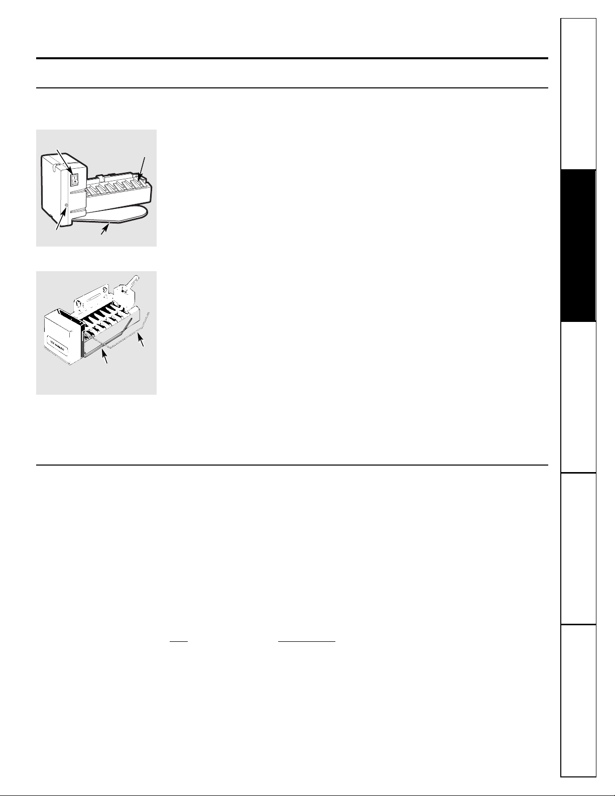
Icemaker
Feeler Arm
Power
Switch
Green
Power Light
Feeler Arm in
the STOP
(up) position
Feeler Arm in
the ON (down)
position
Feeler arm model
Power switch model
There are 2 types of icemakers:
About the automatic icemaker. ge.com
A newly-installed refrigerator may take 12–24 hours to begin making ice.
Automatic Icemaker (on some models)
The icemaker will produce approximately
3 to 3
1
⁄2 lbs. of ice in a 24-hour period,
depending on the freezer compartment
temperature, room temperature, number
of door openings and other use conditions.
There are two types of icemakers: power
switch models and feeler arm models.
If the refrigerator is operated before the
water connection is made to the icemaker,
set the power switch to O (off) or move the
feeler arm to the STOP (up) position.
When the refrigerator has been connected
to the water supply, set the power switch to
the I (on) position or move the feeler arm to
the ON (down) position. On power switch
models, the green light will come on.
The icemaker will fill with water when it
cools to 15°F. A newly-installed refrigerator
may take 12 to 24 hours to begin making
ice cubes.
Once the icemaker starts to make ice,
it may take up to 48 hours to fill the bin,
depending on the temperature settings
and number of door openings.
You will hear a buzzing sound each time
the icemaker fills with water.
Throw away the first few batches of ice
to allow the water line to clear.
Be sure nothing interferes with the sweep
of the feeler arm.
When the bin fills to the level of the feeler
arm, the icemaker will stop producing ice.
It is normal for several cubes to be joined
together.
If ice is not used frequently, old ice cubes
will become cloudy, taste stale, shrink or
fuse together.
On power switch models, the green power
light will blink if ice cubes get stuck in the
icemaker. To correct this, set the power
switch to O (off) and remove the cubes.
Set the power switch to I (on) to restart the
icemaker. After the icemaker has been
turned on again, there will be a delay of
about 45 minutes before the icemaker
resumes operation.
NOTE: In homes with lower-than-average water
pressure, you may hear the icemaker cycle multiple
times when making one batch of ice.
Icemaker Accessory Kit
If your refrigerator did not already come
equipped with an automatic icemaker,
an icemaker accessory kit is available at
extra cost.
Check the back of the refrigerator for the
specific icemaker kit needed for your model.
This refrigerator will accept accessory icemaker IM4A or IM6. Use instruction sheet L
supplied in the kit for assembly inside freezer compartment.
To facilitate installation of an icemaker kit, the following parts are included with your
refrigerator:
Part Part Number
Ice Fill Cup WR29X10074
Ice Fill Tube WR17X12339
Ice Fill Tube Seal WR17X12337
NOTE: It is important that you DO NOT discard these parts, as they will be needed if
you plan to install accessory icemaker kit IM4A or IM6.
Page 10

10
Consumer Support Troubleshooting Tips
Operating Instructions Safety InstructionsInstallation Instructions
Care and cleaning of the refrigerator.
Cleaning the Outside
The door handles and trim. Clean with
a cloth dampened with soapy water.
Dry with a soft cloth.
Keep the outside clean. Wipe with a clean
cloth lightly dampened with kitchen
appliance wax or mild liquid dish
detergent. Dry and polish with a clean,
soft cloth.
The stainless steel panels and door handles
(on some models) can be cleaned with
a commercially available stainless steel
cleaner. Do not use appliance wax or polish
on the stainless steel.
Do not wipe the refrigerator with a soiled dish cloth
or wet towel. These may leave a residue that
can erode the paint. Do not use scouring pads,
powdered cleaners, bleach or cleaners containing
bleach because these products can scratch and
weaken the paint finish.
Cleaning the Inside
To help prevent odors, leave an open box of
baking soda in the fresh food and freezer
compartments.
Unplug the refrigerator before cleaning. If this
is not practical, wring excess moisture out
of sponge or cloth when cleaning around
switches, lights or controls.
Use warm water and baking soda solution—
about a tablespoon (15 ml) of baking soda
to a quart (1 liter) of water. This both cleans
and neutralizes odors. Thoroughly rinse
and wipe dry.
Avoid cleaning cold glass shelves (on some models)
with hot water because the extreme temperature
difference may cause them to break. Handle glass
shelves carefully. Bumping tempered glass can cause
it to shatter.
Do not wash any plastic refrigerator parts in the
dishwasher.
Do not clean with any products containing detergent,
bleach or ammonia. They may damage the
refrigerator.
Condenser
There is no need for routine condenser
cleanings in normal home operating
environments. However, in environments
that may be particularly dusty or greasy, the
condenser should be cleaned periodically
for efficient refrigerator operation.
For models with a base grille, the grille must
be removed in order to clean the condenser.
To remove the base grille:
Grasp it about 6″ from each end and pull
its bottom edge toward you.
To replace the base grille:
Insert the tops of the metal clips into the
oval vents, making sure one of the plastic
tabs on the back of the grille goes into each
of the oval vents. Then push the bottom of
the grille forward until it snaps into place.
Cleaning the condenser:
Sweep away or vacuum up dust.
For models with a base grille, reach the
condenser by inserting a brush or vacuum
hose into the oval holes.
For models without a base grille, reach the
condenser by inserting a brush or vacuum
hose under the bottom of the refrigerator.
For best results, use a brush specially
designed for this purpose. It is available
at most appliance parts stores.
Behind the Refrigerator
Be careful when moving the refrigerator
away from the wall. All types of floor
coverings can be damaged, particularly
cushioned coverings and those with
embossed surfaces.
BEFORE moving the refrigerator away from the wall,
be sure to adjust the leveling legs up. (See Rollers
and Leveling Legs.)
Pull the refrigerator straight out and return
it to position by pushing it straight in.
Moving the refrigerator in a side direction
may result in damage to the floor covering
or refrigerator.
When pushing the refrigerator back, make sure you
don’t roll over the power cord or icemaker supply line
(on some models).
Page 11
11
ge.com
Preparing for Vacation
For long vacations or absences, remove
food and unplug the refrigerator. Move
the refrigerator control to the 1 (off) position
and clean the interior with a baking soda
solution of one tablespoon (15 ml) of
baking soda to one quart (1 liter) of water.
Leave the doors open.
Set the icemaker power switch to the O (off)
position or move the feeler arm to the STOP
(up) position (depending on model) and
shut off the water supply to the refrigerator.
If the temperature can drop below freezing,
have a qualified servicer drain the water
supply system (on some models) to prevent
serious property damage due to flooding.
Preparing to Move
Secure all loose items such as grille,
shelves and drawers by taping them
securely in place to prevent damage.
Be sure the refrigerator stays in an upright position
during moving.
Replacing the light bulb.
Setting either or both controls to 1 (off) does not remove power to the light circuit.
Refrigerator Compartment—Upper Light
CAUTION: Light bulb may be hot.
Unplug the refrigerator.
The bulb is located at the top of the
compartment near the opening.
Replace with an appliance bulb of
the same or lower wattage.
Plug the refrigerator back in.
Consumer SupportTroubleshooting TipsOperating Instructions
Safety Instructions
Installation Instructions
Page 12
12
BEFORE YOU BEGIN
Read these instructions completely and carefully.
•
IMPORTANT – Save these
instructions for local inspector’s use.
•
IMPORTANT – Observe all
governing codes and ordinances.
• Note to Installer – Be sure to leave these
instructions with the Consumer.
• Note to Consumer – Keep these instructions
for future reference.
• Skill level – Installation of this appliance requires
basic mechanical skills.
• Completion time – Refrigerator Installation
15 minutes.
• Proper installation is the responsibility of the
installer.
• Product failure due to improper installation is not
covered under the Warranty.
• Do not install the refrigerator where the temperature
will go below 60°F (16°C) because it will not run often
enough to maintain proper temperatures.
• Do not install the refrigerator where the temperature
will go above 100°F (37°C) because it will not perform
properly.
• Install it on a floor strong enough to support it fully
loaded.
REFRIGERATOR LOCATION
If you have questions, call 1.800.GE.CARES or visit our Website at: ge.com
Installation
Refrigerator
Instructions
Models GTH21 and GTL21
Allow the following clearances for ease of installation,
proper air circulation and plumbing and electrical
connections.
• Sides 1/8″ (3 mm)
• Top 1″ (25 mm)
• Back 1″ (25 mm)
If the refrigerator is to be installed next to a wall on the
hinge side, allow 5/16″ (8 mm) door clearance.
CLEARANCES
If the refrigerator has an icemaker, it will have
to be connected to a cold water line. A GE water
supply kit (containing tubing, shutoff valve, fittings
and instructions) is available at extra cost from your
dealer or by visiting our Website at ge.com or Parts
and Accessories, 800.626.2002.
WATER SUPPLY TO THE ICEMAKER
(ON SOME MODELS)
Rollers allow you to move the refrigerator away from the
wall for cleaning.
Leveling Legs near each front corner of the refrigerator,
next to the rollers, should be adjusted if any of the
following occurs:
• Refrigerator wobbles due to front roller not being firmly
positioned on the floor.
• Door(s) do not close easily when opened to 45°.
NOTE:
• BEFORE moving the refrigerator away from the wall,
be sure to turn the leveling legs counterclockwise so that
the weight of the refrigerator is fully transferred to the
front rollers.
• The refrigerator will not be level from front to back. It
will have a slight backward tilt for proper door-closing.
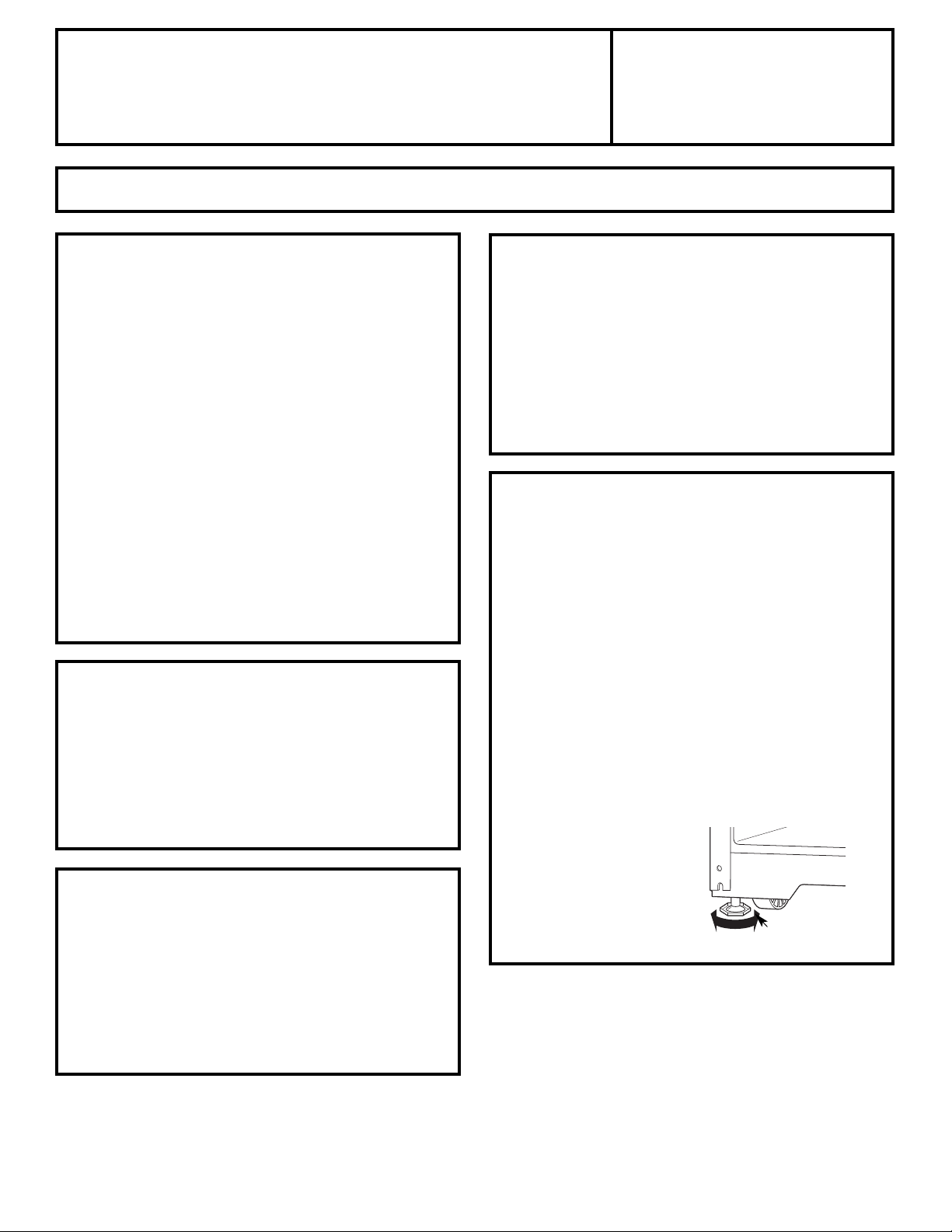
To adjust the leveling legs,
turn the two front leveling
legs clockwise to raise the
front of the refrigerator and
counterclockwise to lower it.
ROLLERS AND LEVELING LEGS
Clockwise to raise
refrigerator
Page 13
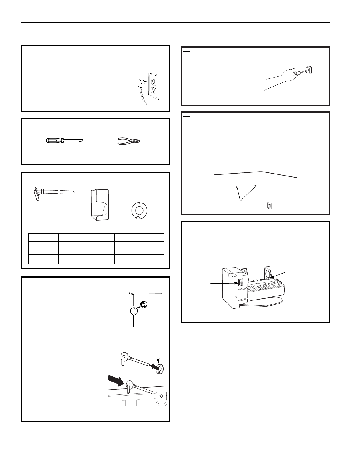
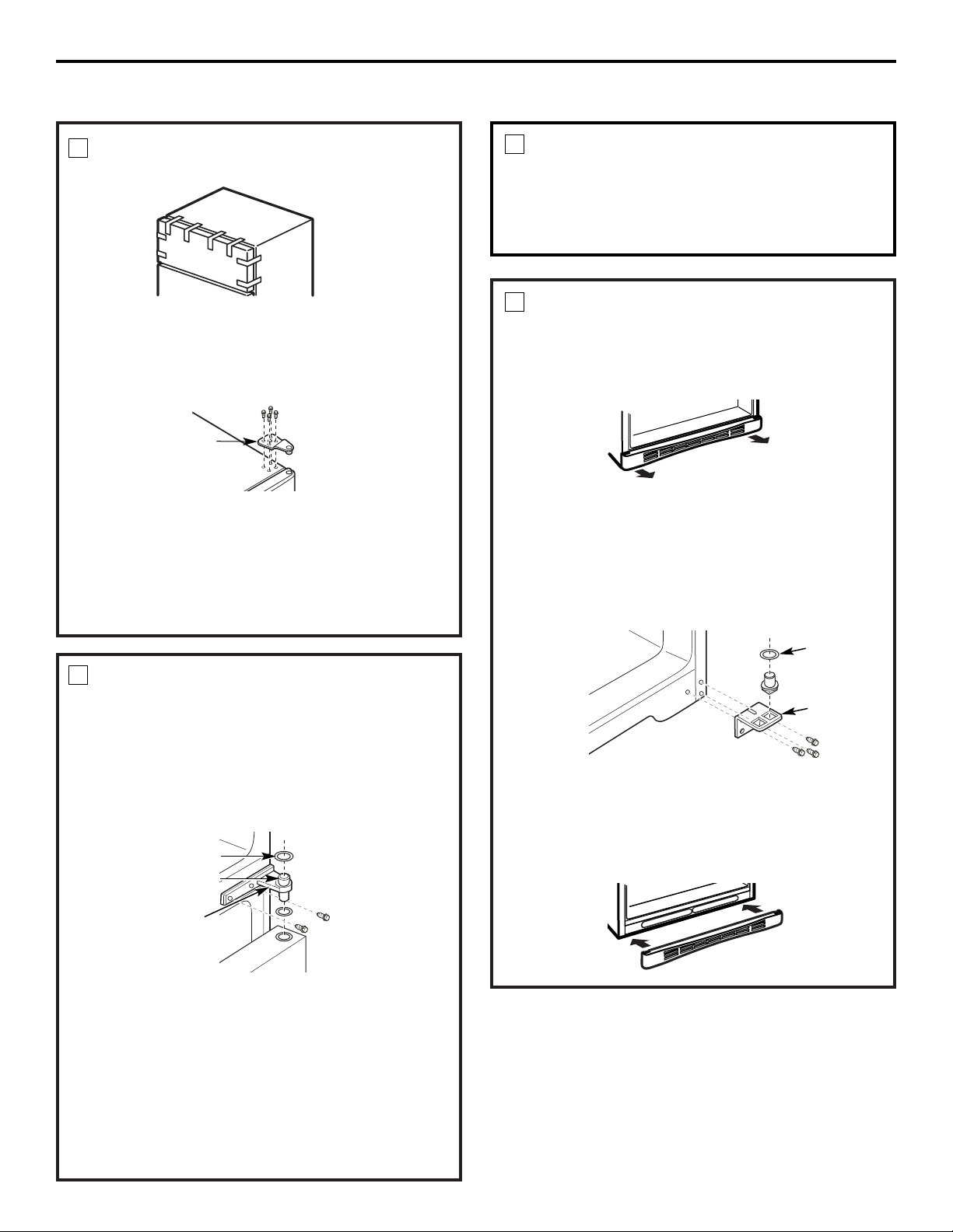
PREPARE FOR INSTALLATION
Inside the freezer, loosen the two mounting screws,
but do not screw them all the way out. If your model
does not have the screws already in the freezer wall,
look for two plug buttons. Remove the plug buttons
and insert the two Phillips head screws. The screws
should extend approximately 1/2″ (13mm) out
from the freezer wall.
3
BEFORE YOU BEGIN
Read each step thoroughly before proceeding.
•
CAUTION – Unplug the
Refrigerator. To eliminate the danger
of electric shock during installation,
you must unplug the refrigerator from
its electrical outlet.
Flat blade and Phillips
screwdrivers
Pliers
TOOLS YOU WILL NEED
REMOVE THE OUTLET COVER
• Remove the outlet cover
with a flat-blade screwdriver.
2
SET POWER SWITCH TO O (off)
Set the icemaker power switch to O (off). Leave
the power switch in the O (off) position until the
refrigerator is connected to the water supply to
prevent premature operation.
4
Power
Switch
INSTALL FILL TUBE
• If the refrigerator already has a
water tube inlet on the back of the
refrigerator, go to Step 2.
• Remove and discard the white plug
from the lower left back corner of
the freezer wall.
• Go to the back of the refrigerator. Find the small
label in the upper right hand corner and peel it
off. Then discard the label.
• Peel one side of the paper away
from the water fill tube seal, slide
the seal along the tube and affix
to the back side of the water
tube inlet flange.
• Remove the adhesive
backing on the opposite side
of the water fill tube seal and
slide the tube into the hole
near the top at the back of the refrigerator. Firmly
press on the inlet to secure it to the refrigerator.
1
Hole for
wire tie
Remove
plug
(Appearance may vary)
13
Side
Back
Seal
Mounting
screws
Installation Instructions
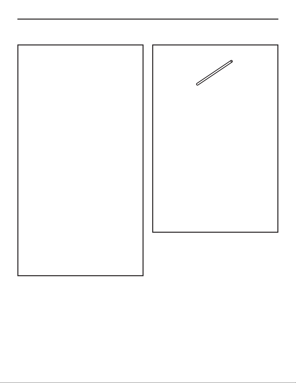
PARTS INCLUDED
1
3
2
NO. DESCRIPTION QUANTITY
1 Water Fill Tube 1
2 Ice Fill Guide 1
3 Water Fill Tube Seal 1
ICEMAKER INSTALLATION INSTRUCTIONS
Page 14

14
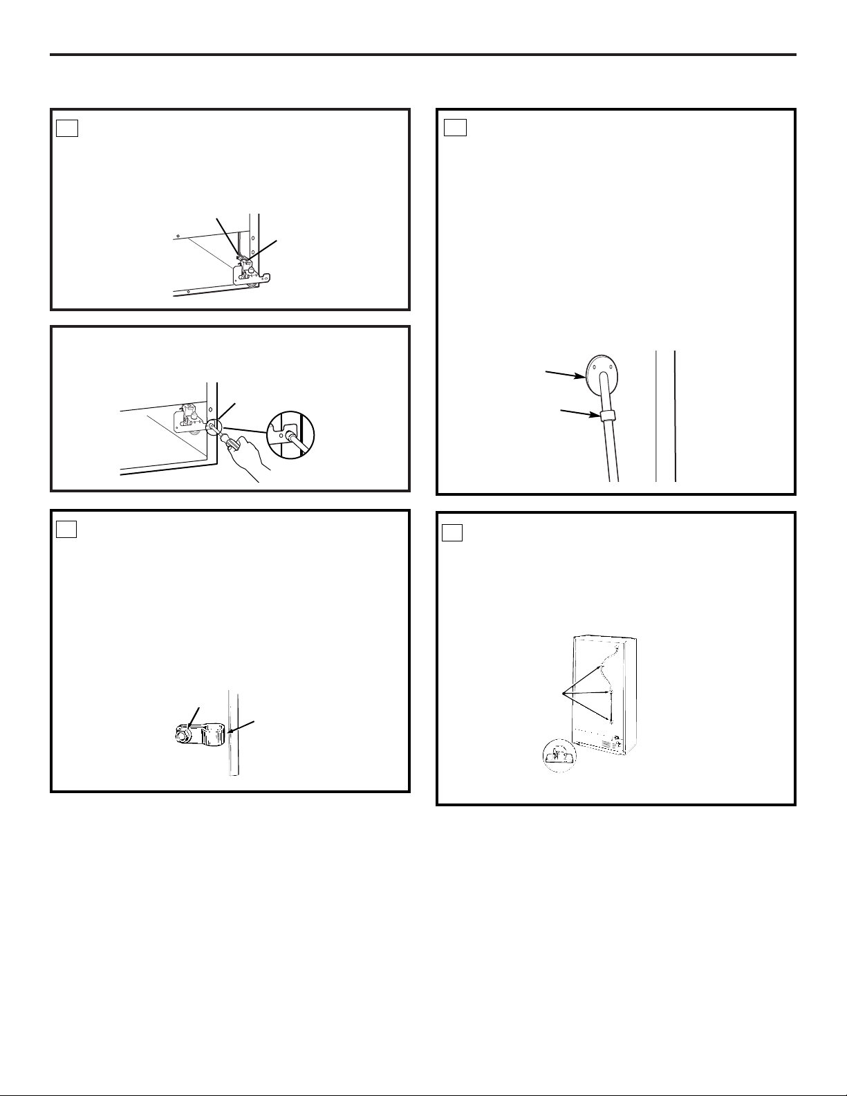
7
PLUG IN THE ICEMAKER
Holding the icemaker in place, insert the icemaker
power cord plug into the socket on the back wall,
making sure the prongs and holes are matched.
Press the plug firmly into the socket. Lock the plug
in place by clipping the restraints onto each side of
the plug. Make sure the restraints click into place.
6
INSTALL THE ICE BUCKET
Place the ice bucket under the icemaker.
Make sure the icemaker power switch is in the
O (off) position.
8
INSTALL THE ICEMAKER FILL CUP
Install the icemaker fill cup (side-mounted) into the
icemaker as shown.
5
MOUNT THE ICEMAKER
• Lift the icemaker so the fill tube extension fits in
the fill cup opening. Hang the icemaker on the
two screws.
Make sure:
• The power cord is still firmly in the socket.
• The fill tube extension extends into the
fill cup opening at the back of the icemaker.
(Check the rear of the refrigerator to make sure
the fill tube has not been pushed out of the back
of the refrigerator).
• The icemaker mounting screws are located in the
uppermost position of the mounting slots.
THEN SECURELY TIGHTEN THE ICEMAKER
MOUNTING SCREWS.
Installation Instructions
REMOVE THE COVER
Use a Phillips head screwdriver to remove the
compressor compartment access cover. This
requires removing six screws which attach the
cover to the back of the refrigerator case.
Be sure to save the screws as the access cover must
be reinstalled later to ensure your refrigerator will
function properly.
9
Icemaker
fill cup
Fill tube
extension
Fill cup
opening
Ice bucket
ICEMAKER INSTALLATION INSTRUCTIONS (CONT.)
Page 15
15
Installation Instructions
ATTACH THE WATER VALVE
• Locate the female connector plug. Plug the
female connector onto the male terminals on
the water valve. Either wire can go on either
terminal.
10
• Fasten the water valve to the cabinet by driving
the Phillips head screw from the kit into the hole
in the cabinet leg.
Female
connector
Male
terminals
Phillips head
screw
12
CONNECT THE WATER LINE
• Make sure there is enough plastic water line to
extend from the water valve to well into the
water tube inlet. Cut off any excess tubing.
• Squeeze the ends of the hose clamp from the
kit with pliers and slide the clamp over the water
tube inlet.
• While still squeezing the clamp, insert the plastic
water line into the inlet as far as it will go
(approximately 1″ [25 mm]).
• Then slide the clamp downward to capture the
plastic water line in place.
• Make sure the fill tube is aimed down.
Water tube
inlet
INSTALL WATER LINE CLAMP
• Attach the metal water line clamp (strain relief)
to the refrigerator. Drive the screw from the kit
through the clamp at the indent into the back
of the cabinet.
• The metal clamp is for the house water line (see
the Water Line Installation Instructions). It is not
to be used for the tubing from the water valve up
to the icemaker.
11
Screw
Strain
relief
Hose clamp
ROUTE AND ATTACH THE
PLASTIC WATER LINE
• Fasten the plastic water line to the back
of the cabinet with adhesive-backed fasteners,
spacing the fasteners as shown to take up slack
in the line.
13
Adhesive-backed fasteners
for plastic water line
Page 16
16
Installation Instructions
15
ATTACH WARRANTY LABEL
A label is provided with this kit to record the date
of installation for warranty purposes. Apply it to the
back of the refrigerator. The icemaker installation
inside the freezer is now complete.
WATER VALVE INSTALLED
Refer to the Water Line Installation Instructions
for connection to the home water supply. After
water line installation is completed, set the
icemaker power switch to I (on).
The icemaking cycle will not begin until the icemaker
and freezer compartment reach operating temperature,
then icemaking will begin automatically.
14
ICEMAKER INSTALLATION INSTRUCTIONS (CONT.)
Page 17
17
INSTALLING THE WATER LINE
(ON SOME MODELS)
Recommended copper water supply kits are WX8X2,
WX8X3 or WX8X4, depending on the amount of
tubing you need. Approved plastic water supply lines
are GE SmartConnect™Refrigerator Tubing
(WX08X10002, WX08X10006, WX08X10015 and
WX08X10025).
When connecting your refrigerator to a GE Reverse
Osmosis Water System, the only approved installation
is with a GE RVKit. For other reverse osmosis water
systems, follow the manufacturer’s recommendations.
This water line installation is not warranted by the
refrigerator or icemaker manufacturer. Follow these
instructions carefully to minimize the risk of expensive
water damage.
Water hammer (water banging in the pipes) in house
plumbing can cause damage to refrigerator parts and
lead to water leakage or flooding. Call a qualified
plumber to correct water hammer before installing the
water supply line to the refrigerator.
To prevent burns and product damage, do not hook
up the water line to the hot water line.
If you use your refrigerator before connecting the
water line, make sure the icemaker power switch is in
the O (off) position (on power switch models) or the
feeler arm is in the STOP (up) position (on feeler arm
models).
Do not install the icemaker tubing in areas where
temperatures fall below freezing.
When using any electrical device (such as a power
drill) during installation, be sure the device is double
insulated or grounded in a manner to prevent the
hazard of electric shock, or is battery powered.
All installations must be in accordance with local
plumbing code requirements.
BEFORE YOU BEGIN
Installation Instructions
WHAT YOU WILL NEED
• Copper or GE SmartConnect™Refrigerator Tubing
kit, 1/4″ outer diameter to connect the refrigerator
to the water supply. If using copper, be sure both ends
of the tubing are cut square.
To determine how much tubing you need: Measure
the distance from the water valve on the back of the
refrigerator to the water supply pipe. Then add 8′
(2.4 m). Be sure there is sufficient extra tubing to
allow the refrigerator to move out from the wall
after installation.
GE SmartConnect™Refrigerator Tubing Kits are
available in the following lengths:
2′ (.6 m) – WX08X10002
6′ (1.8 m) – WX08X10006
15′ (4.6 m) – WX08X10015
25′ (7.6 m) – WX08X10025
NOTE: The only GE approved plastic tubing is that
supplied in GE SmartConnect™Refrigerator Tubing
kits. Do not use any other plastic water supply line
because the line is under pressure at all times. Certain
types of plastic will crack or rupture with age and cause
water damage to your home.
Page 18

18
INSTALLING THE WATER LINE (CONT.)
• A GE water supply kit (containing tubing, shutoff
valve and fittings listed below) is available at extra
cost from your dealer or from Parts and Accessories,
800.626.2002.
• A cold water supply. The water pressure must be
between 20 and 120 p.s.i. (1.4–8.1 bar).
• Power drill.
• 1/2″ or adjustable wrench.
• Straight and Phillips blade screwdriver.
• Two 1/4″ outer diameter compression nuts and
2 ferrules (sleeves)—to connect the copper tubing to
the shutoff valve and the refrigerator water valve.
OR
• If you are using a GE SmartConnect™Refrigerator
Tubing kit, the necessary fittings are preassembled to
the tubing.
• If your existing copper water line has a flared fitting
at the end, you will need an adapter (available at
plumbing supply stores) to connect the water line to
the refrigerator OR you can cut off the flared fitting
with a tube cutter and then use a compression fitting.
Do not cut formed end from GE SmartConnect
™
Refrigerator tubing.
• Shutoff valve to connect to the cold water line.
The shutoff valve should have a water inlet with a
minimum inside diameter of 5/32″ at the point of
connection to the COLD WATER LINE. Saddle-type
shutoff valves are included in many water supply kits.
Before purchasing, make sure a saddle-type valve
complies with your local plumbing codes.
WHAT YOU WILL NEED (CONT.)
Installation Instructions
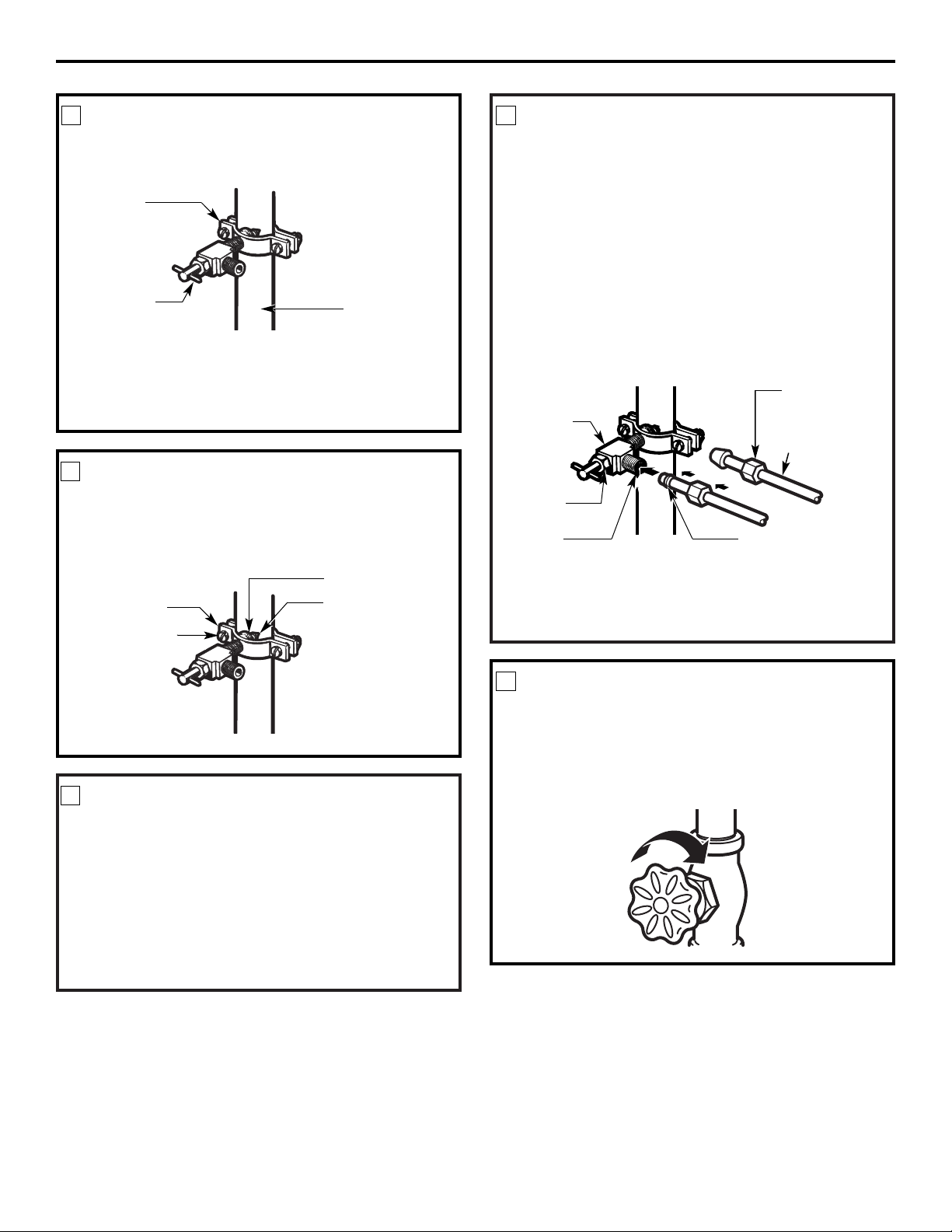
SHUT OFF THE MAIN WATER
SUPPLY
Turn on the nearest faucet long enough to clear
the line of water.
Install the shutoff valve on the nearest frequently used
drinking water line.
1
Choose a location for the valve that is easily
accessible. It is best to connect into the side of a
vertical water pipe. When it is necessary to connect
into a horizontal water pipe, make the connection
to the top or side, rather than at the bottom, to
avoid drawing off any sediment from the water pipe.
CHOOSE THE VALVE LOCATION
2
Drill a 1/4″ hole in the water pipe (even if using a
self-piercing valve), using a sharp bit. Remove any
burrs resulting from drilling the hole in the pipe.
Take care not to allow water to drain into the drill.
Failure to drill a 1/4″ hole may result in reduced
ice production or smaller cubes.
DRILL THE HOLE FOR THE VALVE
3
Page 19
19
Place the compression nut and ferrule (sleeve)
for copper tubing onto the end of the tubing and
connect it to the shutoff valve.
Make sure the tubing is fully inserted into the valve.
Tighten the compression nut securely.
For plastic tubing from a GE SmartConnect
™
Refrigerator Tubing kit, insert the molded end
of the tubing into the shutoff valve and tighten
compression nut until it is hand-tight; then tighten
one additional turn with a wrench. Overtightening
may cause leaks.
NOTE: Commonwealth of Massachusetts Plumbing
Codes 248CMR shall be adhered to. Saddle valves
are illegal and use is not permitted in Massachusetts.
Consult with your licensed plumber.
CONNECT THE TUBING
TO THE VALVE
7
Turn the main water supply on and flush out the
tubing until the water is clear.
Shut the water off at the water valve after about
one quart (1 liter) of water has been flushed
through the tubing.
FLUSH OUT THE TUBING
8
Installation Instructions
Saddle-Type
Shutoff Valve
Compression
Nut
SmartConnect
™
Tubing
Packing Nut
Outlet Valve
Ferrule (sleeve)
Fasten the shutoff valve to the cold water pipe with
the pipe clamp.
NOTE: Commonwealth of Massachusetts Plumbing
Codes 248CMR shall be adhered to. Saddle valves
are illegal and use is not permitted in Massachusetts.
Consult with your licensed plumber.
FASTEN THE SHUTOFF VALVE
4
Tighten the clamp screws until the sealing washer
begins to swell.
NOTE: Do not overtighten or you may crush the
tubing.
TIGHTEN THE PIPE CLAMP
5
Route the tubing between the cold water line and
the refrigerator.
Route the tubing through a hole drilled in the wall
or floor (behind the refrigerator or adjacent base
cabinet) as close to the wall as possible.
NOTE: Be sure there is sufficient extra tubing
to allow the refrigerator to move out from the wall
after installation.
ROUTE THE TUBING
6
Washer
Inlet End
Pipe Clamp
Clamp Screw
Vertical Cold
Water Pipe
Saddle-Type
Shutoff Valve
Pipe Clamp
Page 20
20
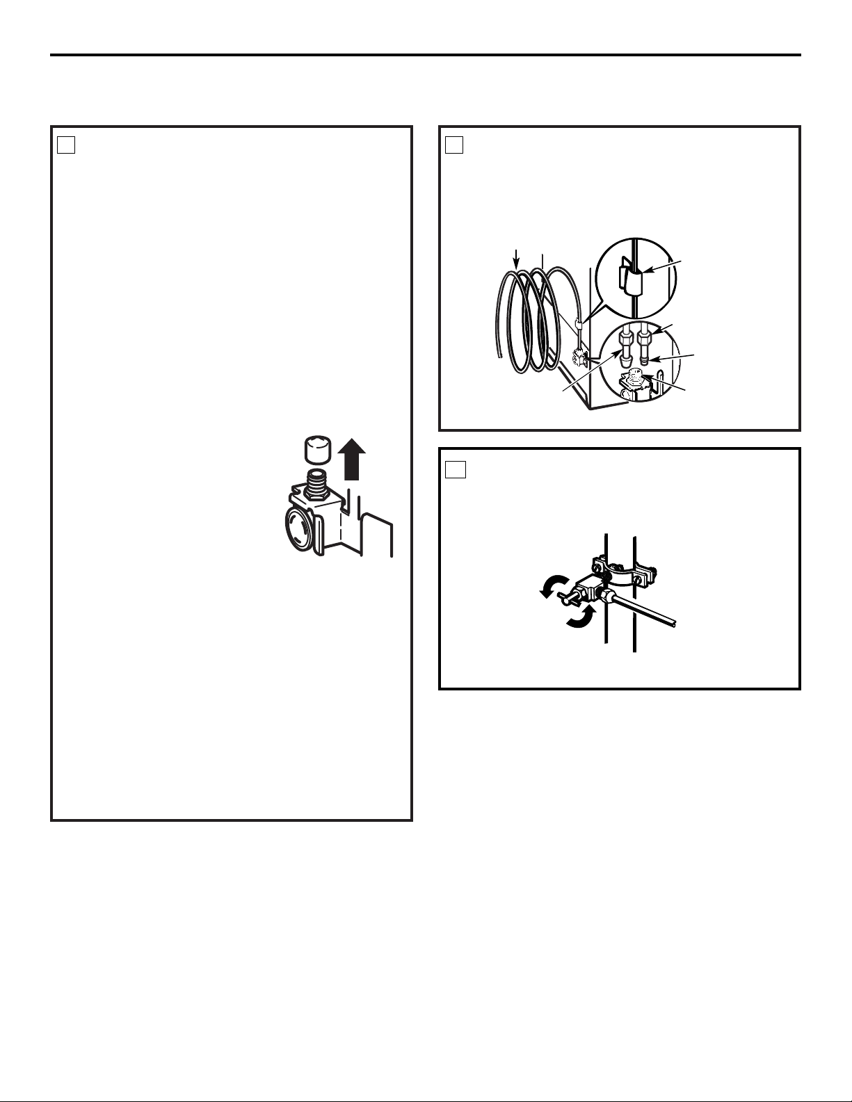
NOTES:
• Before making the connection to the refrigerator,
be sure the refrigerator power cord is not
plugged into the wall outlet.
• We recommend installing a water filter if your
water supply has sand or particles that could clog
the screen of the refrigerator’s water valve. Install
it in the water line near the refrigerator. If using
GE SmartConnect™Refrigerator Tubing kit, you
will need an additional tube (WX08X10002) to
connect the filter. Do not cut plastic tube to
install filter.
Remove the screws holding the right side of the
access cover. Fold back the cover.
Remove the plastic flexible cap
from the water valve
(refrigerator connection).
Place the compression nut and
ferrule (sleeve) onto the end of
the tubing as shown. On GE
SmartConnect™Refrigerator
Tubing kit, the nuts are already
assembled to the tubing.
Insert the end of the tubing into the water valve
connection as far as possible. While holding the
tubing, tighten the fitting.
For plastic tubing from a GE SmartConnect
™
Refrigerator Tubing kit, insert the molded end
of the tubing into the water valve connection and
tighten compression nut until it is hand-tight;
then tighten one additional turn with a wrench.
Overtightening may cause leaks.
Fasten the tubing into the clamp provided to hold
it in a vertical position. You may need to pry open
the clamp.
CONNECT THE TUBING TO THE
REFRIGERATOR
9
Installation Instructions
Tighten any connections that leak.
TURN THE WATER ON AT THE
SHUTOFF VALVE
10
Reattach the access cover.
1/4″ Compression Nut
Tubing Clamp
1/4″ Tubing
Ferrule (sleeve)
Refrigerator
Connection
SmartConnect
™
Tubing
INSTALLING THE WATER LINE (CONT.)
One of the illustrations below will look like the
connection on your refrigerator.
CONNECT THE TUBING TO THE
REFRIGERATOR (CONT.)
9
Page 21

When reversing the door swing:
• Read the instructions all the way through before
starting.
• Handle parts carefully to avoid scratching paint.
• Set screws down by their related parts to avoid using
them in the wrong places.
• Provide a non-scratching work surface for
the doors.
IMPORTANT: Once you begin, do not move the
cabinet until door-swing reversal is completed.
These instructions are for changing the hinges from
the right side to the left side—if you ever want to change
the hinges back to the right side, follow these same
instructions and reverse all references to left and right.
Unplug the refrigerator from its electrical outlet.
Empty all door shelves, including the dairy
compartment.
IMPORTANT NOTES
5/16″ socket and ratchet
TOOLS YOU WILL NEED
Phillips screwdriver
Putty knife or
thin-blade screwdriver
Masking tape
21
On power switch models, set the icemaker power
switch to the l (on) position. On feeler arm models,
move the feeler arm to the ON (down) position. The
icemaker will not begin to operate until it reaches
its operating temperature of 15°F (–9°C) or below.
It will then begin operation automatically.
NOTE: In lower water pressure conditions, the
water valve may turn on up to 3 times to deliver
enough water to the icemaker.
Arrange the coil of tubing so that it does not vibrate
against the back of the refrigerator or against the
wall. Push the refrigerator back to the wall.
PLUG IN THE REFRIGERATOR
11
START THE ICEMAKER
Power
switch
Power switch model
Feeler Arm in the
STOP (up) position
Feeler Arm in
the ON (down) position
Feeler arm model
Installation Instructions
REVERSING THE DOOR SWING
Make sure proper
ground exists
before use.
IMPORTANT: PLEASE READ CAREFULLY
FOR PERSONAL SAFETY, THIS APPLIANCE
MUST BE PROPERLY GROUNDED.
The power cord of this appliance is equipped
with a 3-prong (grounding) plug that mates with
a standard 3-prong (grounding) wall receptacle
to minimize the risk of electric shock hazard from
this appliance. The customer should have the
wall receptacle and circuit checked by a qualified
electrician to make sure the receptacle is properly
grounded.
Where a standard two-prong wall receptacle is
encountered, it is the personal responsibility and
obligation of the customer to have it replaced with
a properly grounded 3-prong wall receptacle.
DO NOT, UNDER ANY CIRCUMSTANCES, CUT
OR REMOVE THE THIRD (GROUND) PRONG
FROM THE POWER CORD.
Page 22
22
TRANSFER BOTTOM HINGE
BRACKET TO THE LEFT
For models with a base grille, remove it by grasping it
about 6″ from each end and pulling its bottom edge
toward you.
Using a 5/16″ socket and ratchet, remove the 3 screws
from the bottom hinge. Taking care not to misplace
the washer on the bottom hinge, move the bottom
hinge from the right to the left side.
NOTE: If the washer is not on the hinge bracket,
check to see if it is stuck to the bottom of the door.
4
Plastic
Washer
Hinge Bracket
Replace the base grille by inserting the tops of the
metal clips into the oval vents, making sure one of the
plastic tabs on the back of the grille goes into each of
the oval vents. Then push the bottom of the grille
forward until it snaps into place.
REMOVE REFRIGERATOR DOOR
2
Tape the door shut with masking tape.
Remove the center hinge by removing two hinge
screws with a 5/16″ socket and ratchet. Lift the
hinge pin up and out of the door.
NOTE: Do not misplace the washer located on the
underside of the center hinge pin.
Remove the tape and tilt the door away from the
cabinet. Lift the door straight up to free its bottom
socket from the pin in the bottom hinge bracket.
Set the door on a non-scratching surface with the
inside up.
CAUTION: Do not let door drop to the floor.
To do so could damage the door stop.
TRANSFER TOP HINGE TO
THE LEFT
Interchange hinge and screws at top right with screws
at the top left of cabinet.
Do not tighten screws on hinge side at this time.
3
Plastic Washer
Fresh Food Door
Hinge Pin
Center Hinge
Bracket
Installation Instructions
REVERSING THE DOOR SWING (CONT.)
REMOVE FREEZER DOOR
1
Tape the door shut with masking tape.
Remove the tape and tilt the door away from the
cabinet. Lift it off the center hinge pin.
NOTE: Do not misplace the washer located on the top
side of the center hinge pin.
Set the door on a non-scratching surface with
the inside up.
Remove the hinge cover on top of the freezer door.
Remove the four screws with a 5/16″ socket and
ratchet, then lift the hinge straight up to free the
hinge pin from the socket in the top of the door.
Top Hinge
Page 23
Installation Instructions
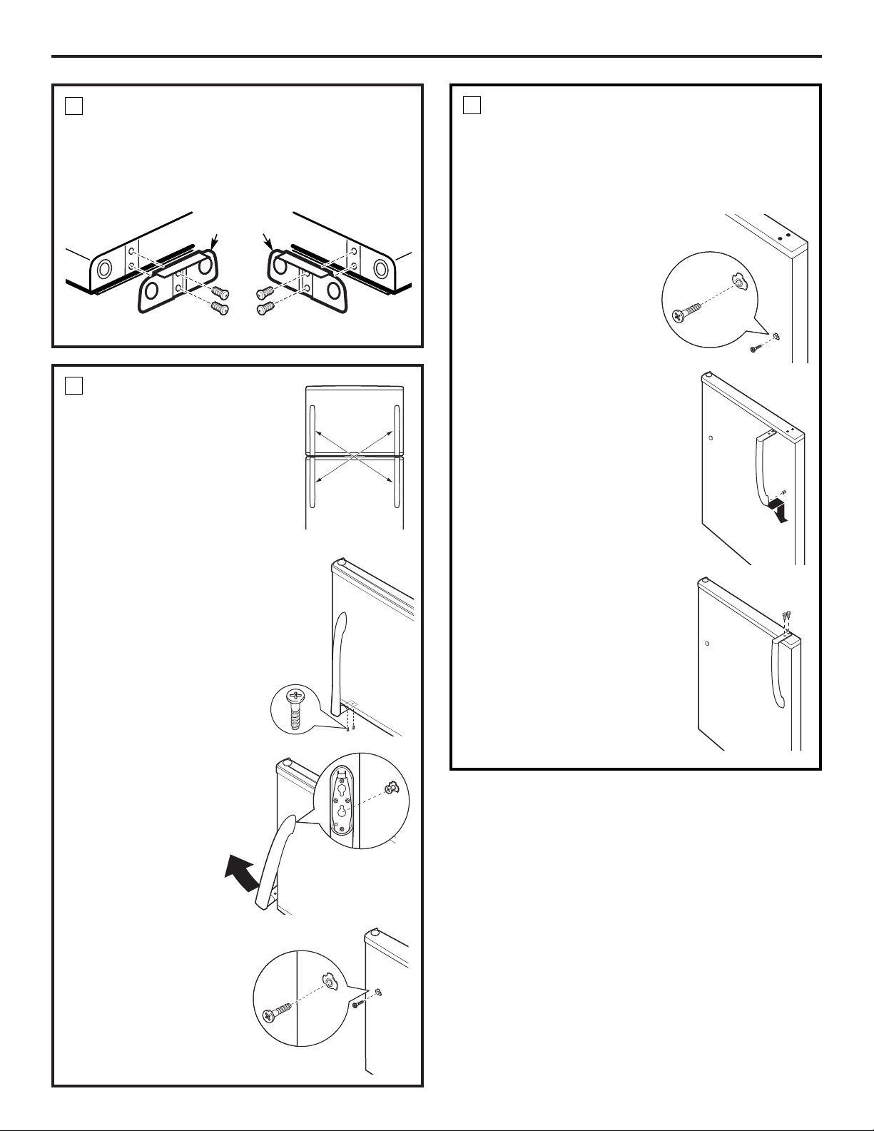
TRANSFER DOOR STOPS
On each door, move the metal door stop from the
right to the left.
Move any screws from the left to the right.
5
23
Door Stop
Door Stop
Left Side
Right Side
REVERSING DOOR HANDLES –
TRANSFER FREEZER DOOR
HANDLE TO THE RIGHT SIDE OF
THE REFRIGERATOR DOOR
(CONT.)
4. Insert the mounting
screw into the surface
of the right side of the
refrigerator door with
a Phillips screwdriver.
5. Align the handle with
the mounting screw.
6. Push the handle down.
7. Secure the top end of
the handle by inserting
two screws and tightening
them with a Phillips
screwdriver.
NOTE: Do not over-tighten.
6
REVERSING DOOR
HANDLES –
TRANSFER
FREEZER DOOR
HANDLE TO THE
RIGHT SIDE OF THE
REFRIGERATOR
DOOR
1. Remove the two screws
securing the bottom end
of the handle with a
Phillips screwdriver.
2. Rotate the handle
out and lift off of
the mounting
screw on the
freezer door.
3. Remove the mounting
screw from the surface
of the freezer door.
6
Page 24
24
Installation Instructions
REVERSING THE DOOR SWING (CONT.)
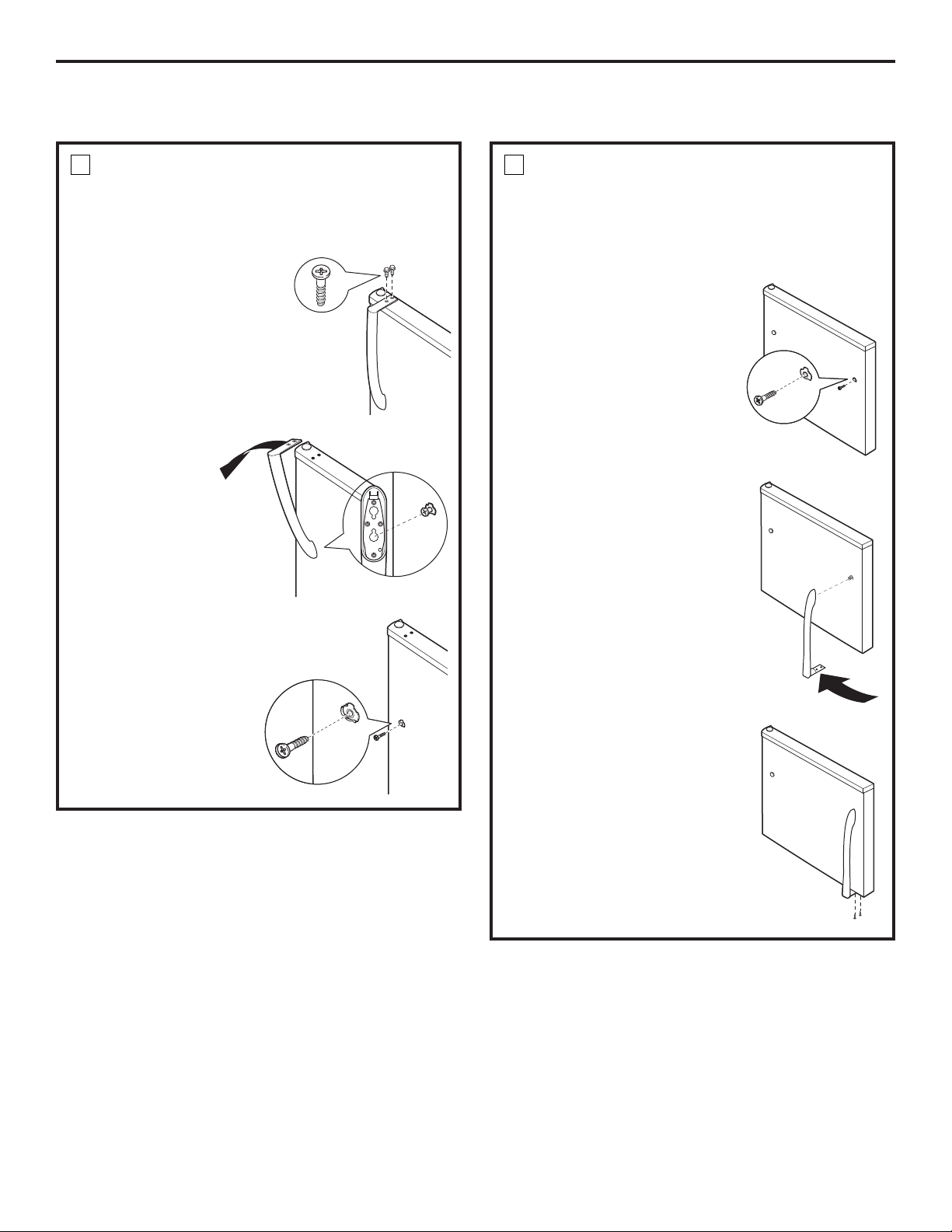
REVERSING DOOR HANDLES –
TRANSFER REFRIGERATOR
DOOR HANDLE TO THE RIGHT
SIDE OF THE FREEZER DOOR
(CONT.)
4. Insert the mounting screw
into the surface of the right
side of the freezer door
with a Phillips screwdriver.
5. Align the handle with
the mounting screw.
6. Rotate the handle.
7. Secure the bottom end
of the handle by inserting
two screws and tightening
them with a Phillips
screwdriver.
NOTE: Do not over-tighten.
7
REVERSING DOOR HANDLES –
TRANSFER REFRIGERATOR
DOOR HANDLE TO THE RIGHT
SIDE OF THE FREEZER DOOR
1. Remove the two screws
securing the top end of
the handle with a Phillips
screwdriver.
2. Rotate the
handle out
and lift off of
the mounting
screw on the
refrigerator
door.
3. Remove the mounting
screw from the surface
of the refrigerator
door.
7
Page 25
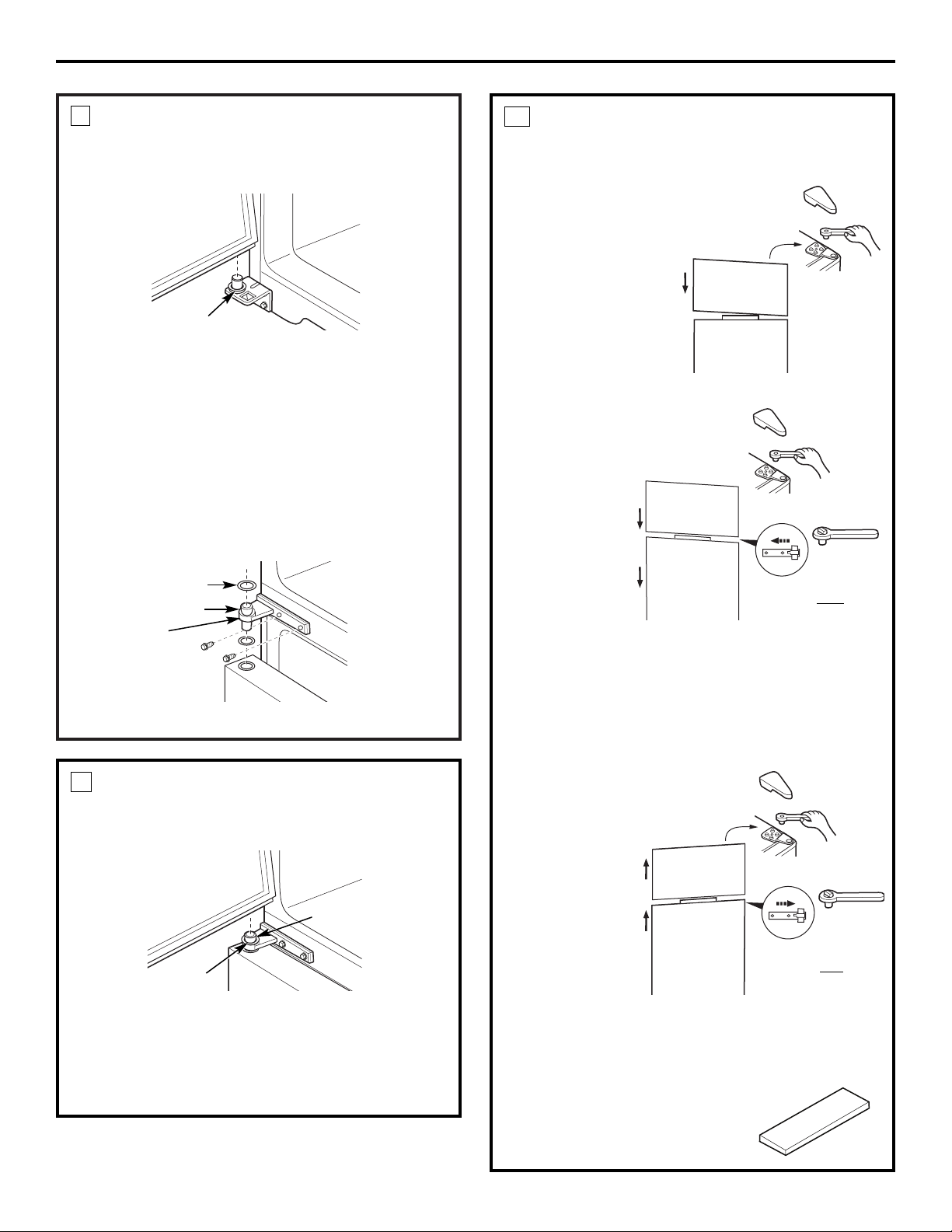
REHANG THE REFRIGERATOR
DOOR
Lower the refrigerator door onto the bottom
hinge pin.
Installation Instructions
8
Screw the two screws into the center hinge location
on the left side with a 5/16″ socket and ratchet.
Straighten the door and place the center hinge pin
into the opening on top of the door. Remember to
include the washer.
Move the door into place, so you can align the center
hinge bracket over the center hinge holes on the left
side. Insert and tighten the two screws with a 5/16″
socket and ratchet.
NOTE: Ensure the washer is in place on top of the
hinge pin.
Plastic
Washer
Plastic Washer
Refrigerator Door
Hinge Pin
Center Hinge
Bracket
REHANG THE FREEZER DOOR
Lower the freezer door onto the center hinge pin.
Be sure the washer is in place.
9
Lift the top hinge so the pin fits into the door socket.
Support the door on the handle side and make sure
the door is straight and the gap between the doors is
even across the front. While holding the door in
place, tighten the top hinge screws.
Center Hinge Pin
Plastic
Washer
25
ADJUST THE DOORS
(IF NEEDED)
If the freezer door is too high:
Remove the hinge
cover on top of the
freezer door and
loosen the four
screws with a 5/16″
socket and ratchet.
Replace the hinge
cover.
If both doors are too high:
1. Remove
the hinge
cover on
top of the
freezer
door and
loosen the
four screws
with a
5/16″
socket and
ratchet.
2. Loosen the two center hinge screws with a 5/16″
socket and ratchet.
3. Slide the center hinge to the left to lower
the doors.
4. Fully tighten all screws and replace top hinge cover.
If both doors are too low:
1. Remove the
hinge cover
on top of
the freezer
door and
loosen the
four screws
with a 5/16″
socket and
ratchet.
2. Loosen the
two center
hinge screws
with a 5/16″ socket and ratchet.
3. Slide the center hinge to the right to raise the
doors.
4. Fully tighten all screws and replace top hinge cover.
NOTE: Save the door spacer.
Doors may settle with use.
10
Loosen screws.
5/16″
Loosen screws. 5/16″
Loosen
screws and
slide left to
lower
doors.
5/16″
Loosen screws. 5/16″
Loosen
screws and
slide right to
raise
doors.
5/16″
Door Spacer
Page 26
26
Consumer Support Troubleshooting Tips
Operating Instructions Safety InstructionsInstallation Instructions
HUMMM...
WHOOSH...
■
The new high efficiency compressor may run faster
and longer than your old refrigerator and you may
hear a high-pitched hum or pulsating sound while
it is operating.
■
You may hear a whooshing sound when the doors close.
This is due to pressure equalizing within the refrigerator.
Normal operating sounds.
Newer refrigerators sound different from older refrigerators. Modern refrigerators
have more features and use newer technology.
■
You may hear the fans spinning at high speeds.
This happens when the refrigerator is first plugged
in, when the doors are opened frequently or when
a large amount of food is added to the refrigerator
or freezer compartments. The fans are helping to
maintain the correct temperatures.
CLICKS, POPS,
CRACKS and CHIRPS
■
You may hear cracking or popping sounds when the
refrigerator is first plugged in. This happens as the
refrigerator cools to the correct temperature.
■
The compressor may cause a clicking or chirping
sound when attempting to restart (this could take
up to 5 minutes).
■
Expansion and contraction of cooling coils during
and after defrost can cause a cracking or popping
sound.
■
On models with an icemaker, after an icemaking
cycle, you may hear the ice cubes dropping into
the ice bucket.
■
On models with a dispenser, during water dispense,
you may hear the water lines move at initial dispense
and after dispenser button is released.
WATER SOUNDS
■
The flow of refrigerant through the freezer cooling
coils may make a gurgling noise like boiling water.
■
Water dropping on the defrost heater can cause a
sizzling, popping or buzzing sound during the
defrost cycle.
■
A water dripping noise may occur during the defrost
cycle as ice melts from the evaporator and flows into
the drain pan.
■
Closing the door may cause a gurgling sound due to
pressure equalization.
Do you hear what I hear? These sounds are normal.
For additional information on normal
icemaker operating sounds, see the
About the automatic icemaker section.
Page 27

Before you call for service… ge.com
Troubleshooting Tips
Save time and money! Review the charts on the following
pages first and you may not need to call for service.
Problem Possible Causes What To Do
Freezer door pops open This is normal if, after • This indicates that there is a good seal on the freezer
when refrigerator door popping open, the freezer door. If the freezer door does not automatically close after
is closed door closed on its own. popping open, the rollers need adjusting. See Rollers and
Leveling Legs.
Door does not close Leveling legs need adjusting. •See Rollers and Leveling Legs.
by itself
Refrigerator does Refrigerator in defrost cycle. • Wait about 40 minutes for defrost cycle to end.
not operate
Refrigerator control in • Move the refrigerator and freezer control to a
1 (off) position. temperature setting.
Refrigerator is unplugged. •Push the plug completely into the outlet.
The fuse is blown/circuit • Replace fuse or reset the breaker.
breaker is tripped.
Vibration or rattling Refrigerator is not resting • Adjust leveling legs (See Rollers and Leveling Legs).
(slight vibration on all four rollers.
is normal)
Motor operates for Normal when refrigerator •Wait 24 hours for the refrigerator to completely
long periods or cycles is first plugged in. cool down.
on and off frequently
Often occurs when large • This is normal.
(Modern refrigerators
amounts of food are
with more storage
placed in refrigerator.
space and a larger
Door left open. • Check to see if package is holding door open.
freezer require more
Hot weather or frequent • This is normal.
operating time. They
door openings.
start and stop often
Temperature controls set •See About the controls.
to maintain even
at the coldest setting.
temperatures.)
Refrigerator or freezer Temperature control not set • See About the controls .
compartment too warm cold enough.
Warm weather or frequent • Set the temperature control one step colder.
door openings. See About the controls.
Door left open. • Check to see if package is holding door open.
Freezer door popped open. • See the problem Freezer door pops open when
refrigerator door is closed.
Frost or ice crystals Door left open. • Check to see if package is holding door open.
on frozen food
Too frequent or too long
(frost within package
door openings.
is normal)
Food blocking freezer air vents. • Move items away from the back wall of the freezer.
Frequent “buzzing” Icemaker power switch is in • Set the power switch to the O (off) position. Keeping it
sound the I (on) position, but the in the I (on) position will damage the water valve.
water supply to the refrigerator
has not been connected.
Small or hollow cubes Water filter clogged. • Replace filter cartridge with new cartridge or with plug.
27
Consumer SupportTroubleshooting TipsOperating InstructionsSafety Instructions Installation Instructions
Page 28
Consumer Support Troubleshooting Tips
Operating Instructions Safety InstructionsInstallation Instructions
28
Problem Possible Causes What To Do
Automatic icemaker Icemaker power switch is •On power switch models, set the power switch to the
(on some models) not on. I (on) position. On feeler arm models, move the feeler
does not work arm to the ON (down) position.
Water supply turned off or • See Installing the water line.
not connected.
Freezer compartment •Wait 24 hours for the refrigerator to completely
too warm. cool down.
Piled up cubes in the storage •Level cubes by hand.
bin cause the icemaker
to shut off.
Ice cubes stuck in icemaker. •Turn off the icemaker, remove cubes and turn the
(Green power light on icemaker back on.
icemaker blinking.)
Ice cubes have Ice storage bin needs cleaning. •Empty and wash bin. Discard old cubes.
odor/taste
Food transmitting odor/taste •Wrap foods well.
to ice cubes.
Interior of refrigerator •See Care and cleaning.
needs cleaning.
Slow ice cube freezing Door left open. •Check to see if package is holding door open.
Temperature control not set •See About the controls.
cold enough.
•A newly installed refrigerator may take 12–24 hours
to begin making ice cubes.
Moisture forms on Not unusual during •Wipe surface dry; then adjust the fresh food control
cabinet surface periods of high humidity. setting one number higher and check again in 24 hours.
between the doors
Refrigerator has odor Foods transmitting • Foods with strong odors should be tightly wrapped.
odor to refrigerator.
• Keep an open box of baking soda in the refrigerator;
replace every three months.
Interior needs cleaning. • See Care and cleaning.
Moisture collects inside Too frequent or too
(in humid weather, air long door openings.
carries moisture into
Open containers of water or • Cover or seal open containers. During a defrost cycle,
refrigerator when doors
warm food in the refrigerator. moisture will be removed from the refrigerator, but may
are opened)
return with long or frequent door openings.
Refrigerator compartment No power at outlet. •Replace fuse or reset the breaker.
light does not work
Light bulb burned out or loose. •See Replacing the light bulbs.
Before you call for service…
Troubleshooting Tips
Page 29

Problem Possible Causes What To Do
Hot air from bottom Normal air flow cooling
of refrigerator motor. In the refrigeration
process, it is normal that
heat be expelled in the
area under the refrigerator.
Some floor coverings will
discolor at these normal
and safe temperatures.
Food freezing in Food too close to the air vent •Move the food away from the air vent (near the
the refrigerator at the back of the refrigerator. controls).
Refrigerator control is set •Move the refrigerator control to a warmer
too cold. temperature setting one increment at a time.
Orange glow Defrost heater is on. • This is normal.
in the freezer
Door bins do not fit The freezer door bins are • Try to install the bins in both doors.
in the door a different size than the
refrigerator door bins.
Controls do not light up Some models do not have • If you can read white numbers on the control setting,
lighted controls. the model does not have lighted controls.
Refrigerator light bulb burned •See Replacing the light bulbs.
out or loose.
Water has poor Water dispenser has not been •Dispense water until all water in system is
taste/odor used for a long time. replenished.
Water in first glass Normal when refrigerator • Wait 24 hours for the refrigerator to completely
is warm is first installed. cool down.
Water dispenser has not been • Dispense water until all water is system is
used for a long time. replenished.
Water system has been drained. • Allow several hours for replenished supply to chill.
No water or ice cube Supply line or shutoff valve •Call a plumber.
production is clogged.
ge.com
29
Consumer SupportTroubleshooting TipsOperating InstructionsSafety Instructions Installation Instructions
Page 30

30
Consumer Support Troubleshooting Tips
Operating Instructions Safety InstructionsInstallation Instructions
Notes.
Page 31

31
General Electric Company
Warranty Registration Department
P.O. Box 32150
Louisville, KY 40232-2150
GE Service Protection Plus
™
GE, a name recognized worldwide for quality and dependability, offers you
Service Protection Plus
™
—comprehensive protection on all your appliances—
No Matter What Brand!
Benefits Include:
• Backed by GE
• All brands covered
• Unlimited service calls
• All parts and labor costs included
• No out-of-pocket expenses
• No hidden deductibles
• One 800 number to call
You will be completely satisfied with our service protection or you may request your money back
on the remaining value of your contract. No questions asked. It’s that simple.
Protect your refrigerator, dishwasher, washer and dryer, range, TV, VCR and much more—any brand!
Plus there’s no extra charge for emergency service and low monthly financing is available. Even icemaker
coverage and food spoilage protection is offered. You can rest easy, knowing that all your valuable
household products are protected against expensive repairs.
Place your confidence in GE and call us in the U.S. toll-free at 800.626.2224
for more information.
*All brands covered, up to 20 years old, in the continental U.S.
We’ll Cover Any Appliance.
Anywhere. Anytime.*
Please place in envelope and mail to:
✁
Cut here
Page 32

32
Consumer Product Ownership Registration
Important
Mail
Today!
GE Consumer & Industrial
Appliances
General Electric Company
Louisville, KY 40225
ge.com
First
Name
Mr. ■■ Ms. ■■ Mrs. ■■ Miss ■■
Street
Address
City
State
Date Placed
In Use
Month
Day
Year
Zip
Code
Apt. #
Last
Name
Phone
Number
_
_
Consumer Product Ownership Registration
Dear Customer:
Thank you for purchasing our product and thank you for placing your confidence in us.
We are proud to have you as a customer!
Follow these three steps to protect your new appliance investment:
Important: If you did not get a registration card with your
product, detach and return the form below to
ensure that your product is registered, or register
online at ge.com.
1
23
Model Number Serial Number
✁
Cut here
Complete and mail
your Consumer
Product Ownership
Registration today.
Have the peace of
mind of knowing we
can contact you in
the unlikely event of
a safety modification.
After mailing the
registration below,
store this document
in a safe place. It
contains information
you will need should
you require service.
Our service number is
800 GE CARES
(800.432.2737).
Read your Owner’s
Manual carefully.
It will help you
operate your new
appliance properly.
Model Number Serial Number
E-mail Address*
* Please provide your e-mail address to receive, via e-mail, discounts, special offers and other
important communications from GE Appliances (GEA).
■■ Check here if you do not want to receive communications from GEA’s carefully selected
partners.
FAILURE TO COMPLETE AND RETURN THIS CARD DOES NOT DIMINISH YOUR
WARRANTY RIGHTS.
For information about GEA’s privacy and data usage policy, go to ge.com and click on
“Privacy Policy” or call 800.626.2224.
Page 33

33
Please place in envelope and mail to:
Veuillez mettre dans une enveloppe et envoyez à :
OWNERSHIP REGISTRATION
P.O. BOX 1780
MISSISSAUGA, ONTARIO
L4Y 4G1
(FOR CANADIAN CONSUMERS ONLY)
Page 34

34
Page 35

35
TERMS AND CONDITIONS:
This warranty applies only for single family domestic use in
Canada when the Refrigerator has been properly installed
according to the instructions supplied by Mabe and is
connected to an adequate and proper utility service.
Damage due to abuse, accident, commercial use, and alteration
or defacing of the serial plate cancels all obligations of this
warranty.
Service during this warranty period must be performed by an
Authorized Mabe Service Agent.
Neither Mabe nor the Dealer is liable for any claims or
damages resulting from failure of the Refrigerator or from
service delays beyond their reasonable control.
To obtain warranty service, purchaser must present the original
Bill of Sale. Components repaired or replaced are warranted
through the remainder of the original warranty period only.
This warranty is extended to the original purchaser and any
succeeding owner for products purchased for home use within
Canada. In home warranty service will be provided in areas
where it is available and deemed reasonable by Mabe to provide.
This warranty is in addition to any statutory warranty.
WHAT IS NOT COVERED:
• Owner is responsible to pay for service calls related to
product installation and/or teaching how to use the product.
• Damage to finish must be reported within 48 hours following
the delivery of the appliance.
• Damage to finish after delivery.
• Improper installation—proper installation includes adequate
air circulation to the refrigeration system, adequate electrical,
plumbing and other connecting facilities.
• Replacement of house fuses or resetting of circuit breakers.
• Replacement of light bulbs.
• Damage to product caused by accident, fire, floods or acts
of God.
• Loss of food due to spoilage.
• Proper use and care of product as listed in the owner’s
manual, proper setting of controls.
• Product not accessible to provide required service.
• WARRANTOR IS NOT RESPONSIBLE FOR CONSEQUENTIAL
DAMAGES.
IMPORTANT
Keep this warranty and your bill of sale as proof of original purchase and purchase date.
Please have serial number and model number available when calling for service.
Mabe Service is available coast to coast. If further help is
needed concerning this warranty, contact:
Manager, Consumer Relations
Mabe Canada Inc., Consumer Service
1 Factory Lane, Suite 310
Moncton, New Brunswick E1C 9M3
1.800.561.3344
Staple your receipt here.
Proof of the original purchase
date is needed to obtain service
under the warranty.
What is covered How Long Warranted Parts Labour
(From Date of Sale) Repair or Replace
at Mabe’s Option
Compressor GE Profile: Ten (10) Years GE Profile: Ten (10) Years GE Profile: Five (5) Years
GE and All Other GE and All Other GE and All Other
Brands: One (1) Year Brands: One (1) Year Brands: One (1) Year
Sealed System (including GE Profile: Five (5) Years GE Profile: Five (5) Years GE Profile: Five (5) Years
evaporator, condenser GE and All Other GE and All Other GE and All Other
tubing and refrigerant) Brands: One (1) Year Brands: One (1) Year Brands: One (1) Year
All Other Parts One (1) Year One (1) Year One (1) Year
CUSTOMER WARRANTY
(for customers in Canada)
Your refrigerator is warranted to be free of defects in material and workmanship.
EXCLUSION OF IMPLIED WARRANTIES—Your sole and exclusive remedy is product repair as provided in this Limited
Warranty. Any implied warranties, including the implied warranties of merchantability or fitness for a particular purpose,
are limited to one year or the shortest period allowed by law.
Page 36

Consumer Support Troubleshooting Tips
Operating Instructions Safety InstructionsInstallation Instructions
Refrigerator Warranty. (For customers in the United States)
All warranty service provided by our Factory Service Centers,
or an authorized Customer Care
®
technician. To schedule service,
on-line, 24 hours a day, visit us at ge.com, or call 800.GE.CARES
(800.432.2737). Please have serial number and model number
available when calling for service.
For The Period Of: GE Will Replace:
GE and GE PROFILE MODELS:
One Year Any part of the refrigerator which fails due to a defect in materials or workmanship.
From the date of the During this limited one-year warranty, GE will also provide, free of charge, all labor and
original purchase related service to replace the defective part.
Thirty Days Any part of the water filter cartridge which fails due to a defect in materials or workmanship.
(Water filter, if included) During this limited thirty-day warranty, GE will also provide, free of charge, a replacement water
From the original filter cartridge.
purchase date of
the refrigerator
GE PROFILE MODELS ONLY:
Five Years Any part of the sealed refrigerating system (the compressor, condenser, evaporator
(GE Profile models only) and all connecting tubing) which fails due to a defect in materials or workmanship.
From the date of the During this limited five-year sealed refrigerating system warranty, GE will also provide,
original purchase free of charge, all labor and related service to replace the defective part in the sealed
refrigerating system.
■ Service trips to your home to teach you how to use
the product.
■ Improper installation, delivery or maintenance.
■ Failure of the product if it is abused, misused, or used for
other than the intended purpose or used commercially.
■ Loss of food due to spoilage.
■ Replacement of house fuses or resetting of circuit
breakers.
■ Damage caused after delivery.
■ Replacement of the water filter cartridge, if included,
due to water pressure that is outside the specified
operating range or due to excessive sediment in the
water supply.
■ Replacement of the light bulbs, if included, or water filter
cartridge, if included, other than as noted above.
■ Damage to the product caused by accident, fire, floods
or acts of God.
■ Incidental or consequential damage caused by possible
defects with this appliance.
■ Product not accessible to provide required service.
What GE Will Not Cover:
This warranty is extended to the original purchaser and any succeeding owner for products purchased for home
use within the USA. If the product is located in an area where service by a GE Authorized Servicer is not available,
you may be responsible for a trip charge or you may be required to bring the product to an Authorized GE Service
location for service. In Alaska, the warranty excludes the cost of shipping or service calls to your home.
Some states do not allow the exclusion or limitation of incidental or consequential damages. This warranty gives
you specific legal rights, and you may also have other rights which vary from state to state. To know what your
legal rights are, consult your local or state consumer affairs office or your state’s Attorney General.
Warrantor: General Electric Company. Louisville, KY 40225
Staple your receipt here.
Proof of the original purchase
date is needed to obtain service
under the warranty.
EXCLUSION OF IMPLIED WARRANTIES—Your sole and exclusive remedy is product repair as provided in this
Limited Warranty. Any implied warranties, including the implied warranties of merchantability or fitness for a
particular purpose, are limited to one year or the shortest period allowed by law.
36
Page 37

37
Soutien au
consommateur
Conseils de dépannageFonctionnementMesures de sécurité Installation
Instructions de sécurité . . . . . . .38–40
Instructions de fonctionnement
Bacs à légumes . . . . . . . . . . . . . . .43, 44
Clayettes et bacs . . . . . . . . . . . . . . . . .42
Machine à glaçons automatique . . . .45
Réglages . . . . . . . . . . . . . . . . . . . . . . .41
Soins et nettoyage
Remplacement de
l’ampoule électrique . . . . . . . . . . . . .47
Soins et nettoyage . . . . . . . . . . . .46, 47
Instructions d’installation
Installation de la
conduite d’eau . . . . . . . . . . . . . . .53–57
Installation de la
machine à glaçons . . . . . . . . . . . .49–52
Inversion du sens
d’ouverture des portes . . . . . . . . .58–62
Préparation à l’installation
du réfrigérateur . . . . . . . . . . . . . .48, 49
En cas de panne . . . . . . . . . . . . .63–67
Bruits normaux
de fonctionnement . . . . . . . . . . . . . .63
Soutien au consommateur
Garantie . . . . . . . . . . . . . . . . . . . . . . .68
Soutien au consommateur . . . . . . . .72
Écrivez ici le numéro de modèle et le
numéro de série :
Modèle #__________________________
Série # __________________________
Vous trouverez ces numéros sur
l’étiquette grise située à gauche, près
du haut du compartiment réfrigérateur.
Page 38

38
INSTRUCTIONS IMPORTANTES DE SÉCURITÉ.
LISEZ TOUTES LES INSTRUCTIONS AVANT
D’UTILISER VOTRE RÉFRIGÉRATEUR.
AVERTISSEMENT!
N’utilisez cet appareil qu’aux fins prévues dans le présent Manuel du propriétaire.
MESURES DE SÉCURITÉ
Pour utiliser un appareil électroménager électrique, vous devez prendre des mesures de sécurité,
en particulier :
■
■ Vous devez bien installer et placer votre
réfrigérateur, conformément aux Instructions
d’installation avant de l’utiliser.
■
■ Ne permettez jamais aux enfants de grimper, de
monter, de se tenir ou de se pendre aux étagères
de votre réfrigérateur. Ils peuvent endommager
le réfrigérateur et se blesser sérieusement.
■
■ Ne touchez jamais les surfaces froides dans le
compartiment congélation quand vos mains sont
humides ou mouillées. Votre peau peut coller à
ces surfaces extrêmement froides.
■
■ Ne conservez jamais ou n’utilisez jamais
d’essence ou d’autres liquides ou gaz
inflammables à proximité de votre réfrigérateur
ou de tout autre appareil électroménager.
■
■ Dans les réfrigérateurs qui ont des machines à
glaçons, évitez tout contact avec les éléments
mobiles du mécanisme d’éjection ou avec
l’élément chauffant situé à la partie inférieure de
la machine à glaçons. Ne mettez jamais vos doigts
ou vos mains sur le mécanisme de fabrication
automatique de glaçons quand le réfrigérateur
est branché.
■
■ Ne laissez jamais vos doigts dans des endroits où
ils risquent d’être pincés. L’écartement entre les
portes et l’armoire est nécessairement petit. Faites
attention de fermer les portes quand des enfants
se trouvent à proximité.
■
■ Débranchez votre réfrigérateur avant de le
nettoyer et de le réparer.
NOTE : Nous vous recommandons fortement de faire
accomplir tout service par un technicien qualifié.
■
■ Vous ne coupez pas l’alimentation du circuit de la
lumière en tournant l’un des boutons de réglage,
ou les deux, en position 1 (arrêt) (certains modèles
n’ont qu’un réglage).
■
■ Ne recongelez jamais des aliments congelés qui
ont complètement dégelé.
Soutien au
consommateur
Conseils de dépannage
Fonctionnement Mesures de sécuritéInstallation
Page 39

39
Soutien au
consommateur
Conseils de dépannageFonctionnementMesures de sécurité Installation
UTILISATION DE RALLONGES ÉLECTRIQUES
Nous vous recommandons fortement de ne pas utiliser de rallonge électrique, à cause d’un danger de
risques possibles de sécurité dans certaines conditions.
Cependant, si vous devez absolument utiliser un cordon rallonge électrique, il est absolument requis que
vous utilisiez un cordon rallonge trifilaire, avec mise à la terre, certifié UL (aux États-Unis) ou ACNOR
(au Canada), avec prise et fiche à trois conducteurs, et à notation électrique de 15 ampères (minimum)
et 120 volts.
DANGER! RISQUE DE PRISE AU
PIÈGE D’ENFANT
BONNE MISE AU REBUT DE VOTRE RÉFRIGÉRATEUR
L’enfermement et l’asphyxie des enfants ne sont
pas des histoires du passé. Les réfrigérateurs jetés
ou abandonnés sont toujours dangereux... même
s’ils ne doivent rester là que «quelques jours». Si
vous vous débarrassez de votre vieux réfrigérateur,
suivez les instructions suivantes pour prévenir tout
accident.
Avant de jeter votre vieux réfrigérateur ou
congélateur :
■ Enlevez les portes.
■ Laissez les clayettes en place, pour éviter que
des enfants puissent facilement grimper
et se tenir dans votre réfrigérateur.
Réfrigérants
Tous les appareils de réfrigération contiennent des
réfrigérants qui, conformément aux lois fédérales,
doivent être enlevés avant toute élimination de
l'appareil. Si vous vous débarrassez de vieux
appareils de réfrigération, vérifiez, auprès de la
société qui s'occupe de leur élimination, ce que
vous devez faire.
www.electromenagersge.ca
Page 40

40
Soutien au
consommateur
Conseils de dépannage
Fonctionnement Mesures de sécuritéInstallation
BRANCHEMENT ÉLECTRIQUE
Ne coupez ou n’enlevez jamais, en n’importe quelles conditions, la troisième broche (mise à la terre)
de votre cordon d’alimentation. Pour votre sécurité personnelle, vous devez bien mettre à la terre cet
appareil électroménager.
Le cordon d’alimentation de cet appareil est muni
d’une fiche à trois broches (bipolaire avec terre)
qui se met dans une prise murale à trois trous
(bipolaire avec terre), pour réduire le risque de
secousse électrique occasionné par cet appareil.
Faites vérifier la prise murale et le circuit électrique
par un électricien qualifié pour vous assurer que
la prise murale est bien mise à la terre.
Si vous avez une prise murale à deux broches
seulement (sans terre), vous êtes personnellement
responsable et obligé de la faire remplacer par une
bonne prise murale avec terre, bien mise à la terre.
Vous devez toujours brancher votre réfrigérateur à
sa propre prise électrique, qui doit avoir un voltage
correspondant à celui de la plaque signalétique de
votre réfrigérateur.
Le rendement de votre réfrigérateur sera meilleur
et vous éviterez ainsi de surcharger les circuits
électriques et de surchauffer le câblage de votre
maison, et éviterez ainsi tout risque d’incendie
provoqué par des câbles surchauffés.
Ne débranchez jamais votre réfrigérateur en
tirant sur le cordon d’alimentation. Tenez toujours
la fiche fermement et enlevez-la de la prise en
tirant droit.
Réparez ou remplacez immédiatement tout cordon
d’alimentation usé ou endommagé. N’utilisez
jamais de cordon fissuré ou usé sur sa longueur
ou à l’une de ses extrémités.
Pour écarter votre réfrigérateur du mur, faites
attention de ne pas écraser ou d’endommager
le cordon d’alimentation.
LISEZ ET SUIVEZ SOIGNEUSEMENT CES MESURES DE SÉCURITÉ.
CONSERVEZ CES INSTRUCTIONS
INSTRUCTIONS IMPORTANTES DE SÉCURITÉ.
LISEZ TOUTES LES INSTRUCTIONS AVANT
D’UTILISER VOTRE RÉFRIGÉRATEUR.
AVERTISSEMENT!
Page 41

41
Soutien au
consommateur
Conseils de dépannageFonctionnementMesures de sécurité Installation
Réglages de votre réfrigérateur. www.electromenagersge.ca
Réglages de votre réfrigérateur
Initialement, mettez le(s) réglage(s) en position 4. Attendez 24 heures que la température
se stabilise.
Plusieurs ajustements peuvent être requis. Ajustez le(s) réglage(s) une unité à la fois, et
attendez 12 heures après chaque ajustement que le réfrigérateur atteigne la température
que vous avez réglée.
En ajustant le réglage de compartiment réfrigération en position 1, vous arrêtez le
refroidissement du compartiment réfrigération et du compartiment congélation, mais vous
ne coupez pas l’alimentation électrique de votre réfrigérateur. Le réglage de compartiment
congélation (sur certains modèles) n’a aucun effet sur l’alimentation électrique du
compartiment réfrigération.
Vous devez régler la température de votre réfrigérateur en fonction de vos préférences,
votre usage et vos conditions d’utilisation et cela peut nécessiter plus d’un réglage. Parmi
les facteurs qui influencent la température, mentionnons la quantité de nourriture dans
les compartiments réfrigération et congélation, la fréquence des ouvertures de porte et
la température de la nourriture lorsqu’elle est placée dans le compartiment réfrigération.
Les réglages de votre réfrigérateur ressemblent à l’un des réglages suivants :
4
44
Page 42

42
Soutien au
consommateur
Conseils de dépannage
Installation Mesures de sécuritéFonctionnement
Les clayettes et les bacs.
Tous les modèles n’ont pas toutes ces caractéristiques.
Disposition des clayettes
Les clayettes du compartiment réfrigération et du compartiment congélation sont réglables.
Compartiment congélation
Pour enlever :
Soulevez le côté gauche de la clayette et
faites-le glisser à gauche dans le centre
des soutiens de clayette.
Faites tourner le côté droit de la clayette
vers le haut et faites-le sortir des
soutiens de clayette.
Pour remettre en place :
En tenant la clayette diagonalement,
insérez l’extrémité gauche de la clayette
dans le centre des soutiens de clayette
sur la paroi de côté.
Insérez l’extrémité droite de la clayette
dans les soutiens de la clayette sur la
paroi de côté. Faites reposer chaque
extrémité de la clayette en bas des
soutiens de clayette.
Compartiment réfrigération
Clayettes mi-largeur
Une extrémité de la clayette repose sur
un support moulé sur la paroi de côté;
un support de l’autre côté entre dans un
rail situé sur la paroi arrière de l’armoire.
Enlèvement :
Faites basculer la clayette vers le haut
à l’avant.
Soulevez le support pour l’enlever
du rail.
Remise en place :
Tout en faisant basculer la clayette vers
le haut, insérez le crochet du haut situé
à l’arrière de la clayette dans une fente
sur le rail.
Abaissez l’avant de la clayette jusqu’à
ce que le bas de la clayette soit fixé en
place.
NOTE : La clayette à droite du rail est conçue
pour s’accrocher à la fente de droite; la clayette
de gauche doit s’accrocher à la fente de gauche.
Soulevez
pour
dégager
Relevez
Page 43

43
Soutien au
consommateur
Conseils de dépannageFonctionnementMesures de sécurité Installation
Bac à casse-croûte
Vous pouvez mettre ce bac à l’endroit qui
convient le mieux aux besoins de votre
famille.
Pour enlever, faites glisser le bac vers
l’extérieur jusqu’à sa position d’arrêt,
soulevez le bac pour lui faire dépasser
sa position d’arrêt, puis enlevez-le.
Bac à légumes à humidité réglable
Faites glisser le réglage en position HIGH
(élevée) pour obtenir l’humidité maximum
qui est recommandée pour la plupart
des légumes.
Faites glisser le réglage en position LOW
(basse) pour obtenir l’humidité minimum
qui est recommandée pour la plupart
des fruits.
Bacs à fruits et légumes
Vous devez bien essuyer toute eau en excès
qui peut s’accumuler au fond des bacs ou
en dessous des bacs.
Bacs à légumes. www.electromenagersge.ca
Tous les modèles n’ont pas toutes ces caractéristiques.
Page 44

44
Soutien au
consommateur
Conseils de dépannage
Installation Mesures de sécuritéFonctionnement
Pour enlever le couvercle en verre
Pour enlever le cadre
Enlèvement du bacs à légumes.
Tous les modèles n’ont pas toutes ces caractéristiques.
Enlèvement du bac à légumes
Videz la clayette inférieure avant d’essayer
d’enlever les bacs de rangement.
Pour enlever :
Soulevez les bacs légèrement vers le haut
tout en les tirant au delà de leur position
d’arrêt.
Si la porte vous empêche d’enlever les
tiroirs, essayez d’abord d’enlever les bacs à
porte. Si la porte n’offre pas assez d’espace
libre, vous devez rouler le réfrigérateur vers
l’avant jusqu’à ce que la porte s’ouvre
suffisamment pour vous permettre d’enlever
les tiroirs. Parfois, pour faire sortir le
réfrigérateur, vous devez le faire aller vers la
gauche ou vers la droite en le roulant.
Pour enlever le couvercle en verre :
Enlevez le verre, puis le cadre. Quand vous
remettez en place le verre, poussez l’arête
devant fort dans le cadre.
Poussez le couvercle en verre vers le
haut arrière.
Faites glisser le couvercle en verre en
arrière jusqu’à ce que l’arête devant
sorte du cadre.
Faites tourner le côté du couvercle en
verre vers le haut.
Enlevez le couvercle en verre.
Pour enlever le cadre :
Soulevez l’avant du cadre vers le haut
en le tenant à deux mains.
Faites glisser le cadre vers l’avant.
Faites tourner le cadre vers le haut.
Enlevez le cadre.
Page 45

Machine à glaçons automatique. www.electromenagersge.ca
Un réfrigérateur nouvellement installé prend de 12 à 24 heures pour commencer à produire des glaçons.
45
Machine
à glaçons
Bras palpeur
Commutateur de marche
Lumière
verte de
fonctionnement
Soutien au
consommateur
Conseils de dépannageFonctionnementMesures de sécurité Installation
Le bras
palpeur est
en position
STOP (arrêt)
en haut
Le bras
palpeur est
en position
ON (marche)
en bas
Modèle à bras palpeur
Modèle à commutateur de marche
Il y a deux catégories de machine
à glaçons :
Machine à glaçons automatique
(sur certains modèles)
La machine à glaçons produit environ
3 à 3-1/2 lb de glace par 24 heures, selon la
température du compartiment congélation,
la température de la pièce, le nombre de
fois que la porte est ouverte et les autres
conditions d’utilisation.
Il y a deux catégories de machine à glaçons :
le modèle à commutateur de marche et le
modèle à bras palpeur.
Si vous faites fonctionner le réfrigérateur
avant de raccorder l’eau à la machine à
glaçons, mettez le commutateur de marche
en position O ( arrêt) ou amenez le bras
palpeur en position STOP (arrêt) en haut.
Après avoir raccordé le réfrigérateur à
l’alimentation d’eau, mettez le commutateur
de marche en position I (marche) ou amenez
le bras palpeur en position ON (marche)
en bas. Sur les modèles à commutateur de
marche, la lumière verte s’allume.
La machine à glaçons se remplit d’eau
quand elle atteint 15°F. Un réfrigérateur
nouvellement installé prend de 12 à 24 heures
pour commencer à produire des glaçons.
Une fois que la machine à glaçons commence
à produire de la glace, il peut s’écouler
jusqu’à 48 heures avant que le bac ne se
remplisse, tout dépendant du réglage de
température et de la fréquence d’ouverture
de la porte.
Vous entendrez une vibration chaque fois que
la machine à glaçons se remplit d’eau.
Jetez les premiers lots de glaçons pour
permettre à la conduite d’eau de se purger.
Assurez-vous que rien ne gène la course du
bras palpeur.
Quand le bac se remplit jusqu’au niveau du
bras palpeur, la machine à glaçons s’arrête de
produire des glaçons.
Il est normal de trouver des glaçons qui soient
soudés ensemble.
Si vous n’utilisez pas souvent vos glaçons, les
vieux glaçons deviennent opaques, prennent
un mauvais goût, rétrécissent ou collent
ensemble.
Sur les modèles à commutateur de marche,
la lumière verte se met à clignoter si des
glaçons se coincent dans la machine à
glaçons. Pour corriger cette situation, mettez
le commutateur de marche en position O
(arrêt) et enlevez les glaçons. Remettez le
commutateur de marche en position I
(marche) pour remettre en marche la machine
à glaçons. Quand vous remettez en marche
la machine à glaçons, vous devez attendre
45 minutes avant qu’elle se remette à
fabriquer des glaçons.
NOTE : Dans les maisons qui ont une pression d’eau
plus faible que la moyenne, vous pouvez entendre la
machine à glaçons recommencer plusieurs fois son
cycle pour produire une livraison de glaçons.
Trousse accessoire de machine à glaçons
Si votre réfrigérateur n’est pas déjà équipé
d’une machine à glaçons automatique, vous
pouvez acheter une trousse accessoire de
machine à glaçons.
Vérifiez le derrière de votre réfrigérateur pour
le modèle de trousse à glaçons que vous devez
acheter pour votre réfrigérateur.
Ce réfrigérateur est compatible avec les modèles de machines à glaçons (accessoire) IM4A
ou IM6. Consultez le feuillet d’instructions « L » fourni avec la trousse de montage à
l’intérieur du compartiment congélateur.
Afin de faciliter l’installation de la machine à glaçons, les pièces suivantes sont comprises
avec votre réfrigérateur :
Pièce
Numéro de pièce
Godet à glace WR29X10074
Tube à glace WR17X12339
Joint d’étanchéité de tube à glace WR17X12337
NOTE : Il est important de NE PAS jeter ces pièces puisqu’elles seront nécessaires pour
installer l’accessoire machine à glaçons de modèle IM4A ou IM6.
Page 46

46
Soutien au
consommateur
Conseils de dépannage
Installation Mesures de sécuritéFonctionnement
Soins et nettoyage de votre réfrigérateur.
Nettoyage de l’extérieur
Les poignées de porte et les garnitures. Nettoyez
avec un linge trempé dans de l’eau savonneuse.
Séchez avec un linge doux.
Conservez l’extérieur propre. Essuyez avec un linge
propre légèrement humecté de cire à appareil
électroménager ou de détersif liquide à vaisselle
doux. Séchez et polissez avec un linge doux,
propre.
Vous pouvez nettoyer les panneaux et les poignées
de porte en acier inoxydable (sur certains
modèles) avec un nettoyant d’acier inoxydable
vendu sur le marché. N’utilisez pas de cire pour
appareils ménagers sur l’acier inoxydable.
N’essuyez jamais votre réfrigérateur avec un torchon sale
ou une serviette mouillée. Cela peut laisser un résidu qui
risque d’endommager la peinture. N’utilisez jamais de
tampon à récurer, de nettoyant en poudre, d’eau de
javel ou de produit nettoyant contenant un agent de
blanchiment, car ces produits peuvent rayer et
endommager la peinture.
Nettoyage de l’intérieur
Pour aider à empêcher les odeurs, laissez une
boîte ouverte de bicarbonate de soude dans les
compartiments réfrigération et congélation.
Débranchez votre réfrigérateur avant de le nettoyer.
Si ce n’est pas pratique, enlevez toute humidité
au moyen d’une éponge ou d’un chiffon pour
nettoyer autour des commutateurs, des lumières
ou des réglages.
Utilisez une solution d’eau chaude et de
bicarbonate de soude 15 ml (soit une cuillère
à soupe environ) de bicarbonate de soude dans
1 litre (soit une pinte) d’eau. Cette solution
nettoie tout en neutralisant les odeurs. Rincez
et séchez en essuyant.
Évitez de nettoyer les clayettes froides en verre
(sur certains modèles) à l’eau chaude, parce qu’elles
risquent de se casser à cause de la grande différence
de températures. Manipulez avec soins le verre. Vous
pouvez briser en éclats le verre trempé en le heurtant.
Ne lavez aucune pièce en matière plastique de votre
réfrigérateur dans votre machine à laver la vaisselle.
Ne lavez les tiroirs à glaçons qu’à l’eau tiède. Ne les lavez
jamais dans une machine à laver la vaisselle.
Le condenseur
Vous n’avez pas besoin de nettoyer souvent le
condenseur en milieu domestique normal.
Cependant, en milieu particulièrement gras ou
poussiéreux, vous devez nettoyer périodiquement
le condenseur pour obtenir un fonctionnement
efficace de votre réfrigérateur.
Pour les modèles avec grille de base, pour nettoyer
le condenseur vous devez enlever la grille.
Enlèvement de la grille de base :
Enlevez la grille de base en la saisissant à environ
15 cm (6″) de chaque extrémité et en tirant son
bas directement vers vous.
Remise en place de la grille de base :
Insérez le haut des agrafes en métal dans les
ouvertures ovales, en vous assurant que chacun
des taquets en matière plastique de l’arrière de
la grille aille dans chacune des ouvertures ovales.
Poussez ensuite le bas de la grille vers l’avant
jusqu’à ce qu’il se fixe en place.
Nettoyage du condenseur :
Époussetez ou enlevez à l’aide d’un aspirateur
toute la poussière.
Pour les modèles avec grille de base, vous avez
accès au condensateur en insérant une brosse ou
un tuyau d’aspirateur dans les ouvertures ovales.
Pour les modèles sans grille de base, vous avez
accès au condensateur en insérant une brosse
ou un tuyau d’aspirateur en dessous du
réfrigérateur.
Pour obtenir de bons résultats, utilisez une
brosse spécialement conçue à cette fin. Vous la
trouverez en vente dans la plupart des magasins
de pièces d’appareils électroménagers.
Derrière votre réfrigérateur
Faites attention quand vous écartez votre
réfrigérateur du mur. Vous pouvez endommager
votre revêtement de plancher, en particulier
s’il est matelassé ou s’il a une surface en relief.
AVANT d'écarter le réfrigérateur d'un mur, assurez-vous de
bien ajuster les pieds d'inclinaison. (Voir roulettes et pieds
d'inclinaison.)
Tirez le réfrigérateur en ligne droite et remettezle en place en poussant en ligne droite.
Vous pouvez endommager le revêtement de
plancher ou votre réfrigérateur en le déplaçant
latéralement.
Lorsque vous remettez en place votre réfrigérateur,
assurez-vous de ne pas le rouler sur le cordon
d’alimentation ou la conduite d’eau de la machine
à glaçons (sur certains modèles).
Page 47

47
Soutien au
consommateur
Conseils de dépannageFonctionnementMesures de sécurité Installation
www.electromenagersge.ca
Préparation de départ en vacances
Pour de longues vacances ou absences,
enlevez tous vos aliments et débranchez
votre réfrigérateur. Mettez le bouton de
réglage du compartiment congélation en
position 1 (arrêt) et nettoyez l’intérieur avec
une solution de bicarbonate de soude, de
15 ml (une cuillère à soupe) de bicarbonate
de soude pour 1 litre (une pinte) d’eau.
Laissez les portes ouvertes.
Mettez le commutateur de marche de la
machine à glaçons en position O (arrêt) ou
amenez le bras palpeur en position STOP
(arrêt) en haut (selon le modèle)et fermez
l’alimentation d’eau du réfrigérateur.
Si la température risque de descendre en
dessous du point de congélation, demandez
à un technicien qualifié de purger votre
système d’alimentation d’eau (sur certains
modèles) pour empêcher des inondations
pouvant occasionner des dégâts sérieux.
Préparation de déménagement
Fixez en place toutes les pièces mobiles,
comme la grille, les clayettes et les tiroirs, à
l’aide de ruban adhésif, pour empêcher
tout dommage.
Assurez-vous que votre réfrigérateur soit en position
droite pendant le déménagement.
Remplacement de l’ampoule électrique.
Vous ne débranchez pas votre réfrigérateur du circuit d’alimentation électrique en mettant le bouton de réglage
en position 1 (arrêt).
Compartiment réfrigération—Lumière en haut
MISE EN GARDE :
L’ampoule électrique peut être brûlante.
Débranchez le réfrigérateur.
L’ampoule est située en haut du
compartiment réfrigération, près
de l’ouverture.
Remplacez l’ampoule par une ampoule
d’appareil électroménager de même
voltage ou d’un voltage plus bas.
Rebranchez le réfrigérateur.
Page 48

ALIMENTATION D’EAU DE
LA MACHINE À GLAÇONS
(SUR CERTAINS MODÈLES)
Si votre réfrigérateur a une machine à glaçons, il faut le
brancher à une conduite d’eau froide. Vous pouvez
acheter une trousse d’alimentation d’eau GE (contenant
la tuyauterie, le robinet d’arrêt, les joints et les
instructions) chez votre revendeur ou en vous adressant
à notre site Web à l’adresse www.electromenagersge.ca
ou à notre service de Pièces et accessoires au numéro de
téléphone 1.888.261.3055.
Si vous avez des questions, appelez le 1.800.561.3344 ou visitez notre site Web à l’adresse :
www.electromenagersge.ca
Instructions
Réfrigérateur
d’installation
Modèles GTH21 et GTL21
48
DÉGAGEMENTS
Prévoyez les dégagements suivants pour faciliter
l’installation, la bonne circulation d’air et les
raccordements de plomberie et d’électricité.
• Côtés : 3 mm (1/8″)
• Dessus : 25 mm (1″)
• Arrière : 25 mm (1″)
Si un côté ou l’autre de votre réfrigérateur est contre
un mur, laissez 8 mm (5/16″) de dégagement pour
permettre une bonne ouverture de la porte.
EMPLACEMENT DU RÉFRIGÉRATEUR
• N’installez jamais votre réfrigérateur dans un
emplacement où la température ambiante sera
inférieure à 16°C (60°F). Il ne se mettra pas en marche
suffisamment souvent pour maintenir des températures
convenables.
• N’installez jamais votre réfrigérateur dans un
emplacement où la température ambiante sera
supérieure à 37°C (100°F). Il ne fonctionnera pas bien.
• Installez votre réfrigérateur sur un plancher
suffisamment solide pour le porter lorsqu’il est plein.
AVANT DE COMMENCER
Veuillez lire toutes les directives attentivement.
•
IMPORTANT – Conservez ces
instructions pour l’inspecteur local.
•
IMPORTANT – Respectez toutes les
ordonnances et les codes locaux.
•
Note à l’installateur – Assurez-vous de laisser ces
instructions au consommateur.
•
Note au consommateur – Conservez ces
instructions pour référence future.
•
Niveau de compétence – L’installation de cet appareil
nécessite des compétences mécaniques de base.
•
Temps d’installation – Installation du réfrigérateur :
15 minutes.
•
L’installateur est responsable de bien installer ce
réfrigérateur.
•
Toute panne du produit due à une mauvaise
installation n’est pas couverte par la garantie.
Page 49

ROULETTES ET PIEDS
D’INCLINAISON
Les rouleaux vous permettent d’écarter le réfrigérateur
du mur pour faciliter le nettoyage.
Les pieds d’inclinaison près de chaque coin avant du
réfrigérateur, à côté des roulettes, doivent être ajustés si
l’un des événements suivants se produit :
• Le réfrigérateur vacille parce que l’une des roulettes
avant ne touche pas le sol.
• La ou les portes ne se referme pas aisément lorsqu’elle
ouverte à un angle de 45º.
REMARQUE :
• AVANT d’écarter le réfrigérateur du mur, assurez-vous
de tourner les pieds d’inclinaison dans le sens inverse
des aiguilles d’une montre afin que le poids du
réfrigérateur soit entièrement transféré aux roulettes
avant.
• Le réfrigérateur ne sera pas de niveau de l’avant à
l’arrière. Il présentera une légère inclinaison vers
l’arrière pour faciliter la fermeture de la porte.
Instructions d’installation
49
ROULETTES ET PIEDS
D’INCLINAISON
(SUITE)
Pour ajuster les pieds
d’inclinaison, tournez les
deux pieds d’inclinaison
avant dans le sens des
aiguilles d’une montre
pour soulever l’avant du
réfrigérateur et dans le sens
inverse pour l’abaisser.
Sens des aiguilles
d’une montre pour
soulever le
réfrigérateur
INSTRUCTIONS D’INSTALLATION
DE LA MACHINE À GLAÇONS
AVANT DE COMMENCER
Lisez soigneusement chaque étape avant de
commencer.
•
MISE EN GARDE –
Débranchez le réfrigérateur. Pour
éliminer tout danger de secousse
électrique pendant l’installation, vous
devez débrancher la fiche de votre
réfrigérateur de sa prise électrique murale.
Tournevis à lame plate et
Phillips
Pinces
OUTILS NÉCESSAIRES
PIÈCES INCLUSES
1
3
2
N
o
DESCRIPTION QUANTITÉ
1 Tube de remplissage d’eau 1
2 Indicateur du niveau de glace 1
3 Joint d’étanchéité du tube 1
de remplissage d’eau
Page 50

50
PRÉPAREZ VOTRE INSTALLATION
Dans le compartiment du congélation, desserrez
les deux vis de montage, sans les dévisser
complètement. Si votre modèle n’a pas de vis déjà
dans la paroi du compartiment congélation,
trouvez deux capuchons. Enlevez les capuchons
et insérez deux vis à tête Phillips. Les vis doivent
sortir d’environ 13 mm (1/2 po) de la paroi du
compartiment congélation.
3
ENLEVEZ LE COUVERCLE
DE LA PRISE ÉLECTRIQUE
• Enlevez le couvercle de la prise électrique à l’aide
d’un tournevis à lame plate.
2
Côté
Arrière
INSTALLEZ LE RÉCIPIENT DE
REMPLISSAGE DE LA MACHINE
À GLAÇONS
Installez le récipient de remplissage de la machine
à glaçons (montage de côté) dans la machine à
glaçons comme l’indique la figure.
5
METTEZ LE COMMUTATEUR
DE MARCHE EN POSITION
O (arrêt)
Mettez le commutateur de marche de la machine à
glaçons en position O (arrêt). Laissez le commutateur
de marche en position O (arrêt) tant que vous n’avez
pas branché le réfrigérateur à l’alimentation d’eau,
pour éviter toute mise en marche prématurée.
4
Commutateur
de marche
Trou pour lien
métallique
(L’aspect peut varier)
Récipient de
remplissage de la
machine à glaçons
Instructions d’installation
Vis de
montage
INSTRUCTIONS D’INSTALLATION
DE LA MACHINE À GLAÇONS (SUITE)
INSTALLATION DU TUBE DE
REMPLISSAGE D’EAU
• Si un orifice d’entrée pour tube de
remplissage d’eau se trouve déjà à
l’arrière du réfrigérateur, allez à
l’étape 2.
• Retirez et départissez-vous du bouchon
blanc situé dans le coin arrière inférieur
gauche de la paroi du congélateur.
• Allez à l’arrière du réfrigérateur. Repérez la petite
étiquette située dans le coin supérieur droit et décollezla. Jetez l’étiquette.
• Décollez un côté du papier
du joint d’étanchéité du tube
de remplissage, faites glisser
le joint le long du tube puis collez-le
sur l’arrière du rebord de l’orifice
d’entrée pour tube.
• Retirez la doublure adhésive
sur le côté opposé du joint
du tube puis faites glisser
le tube dans l’orifice situé
dans le haut de l’arrière
du réfrigérateur. Pressez
fermement le joint sur l’orifice
d’entrée pour le fixer au réfrigérateur.
1
Enlevez
le bouchon
Joint d’étanchéité
Page 51

Instructions d’installation
BRANCHEZ LA MACHINE
À GLAÇONS
En tenant la machine à glaçons en place, insérez
la fiche de cordon d’alimentation électrique dans
la prise située sur la paroi d’arrière, en vous assurant
de mettre les bonnes broches dans les bons trous.
Pressez fort la fiche dans la prise. Fixez la fiche en
place en agrafant les dispositifs de retenue des deux
côtés de la fiche. Assurez-vous que les dispositifs de
retenue soient fixés en place.
6
MONTEZ LA MACHINE
À GLAÇONS
• Soulevez la machine à glaçons de manière à ce que
la rallonge de conduite d’alimentation d’eau
entre dans l’ouverture du récipient de remplissage.
Accrochez la machine à glaçons aux deux vis de
montage.
Assurez-vous bien que :
• Le cordon d’alimentation électrique soit toujours
bien fixé à la prise.
• La rallonge de conduite d’alimentation d’eau
se trouve toujours bien dans l’ouverture du
récipient de remplissage à l’arrière de la machine
à glaçons (vérifiez à l’arrière du réfrigérateur que
la conduite d’alimentation d’eau n’ait pas été
poussée à l’extérieur du réfrigérateur).
• Les vis de montage se trouvent dans la position
supérieure des fentes de montage.
SERREZ ALORS FORT LES VIS DE MONTAGE
DE LA MACHINE À GLAÇONS.
7
Rallonge de conduite
d’alimentation d’eau
Ouverture du récipient
de remplissage
INSTALLEZ LE BAC À GLAÇONS
Mettez le bac à glaçons sous la machine à glaçons.
Assurez-vous que le commutateur de marche de
la machine à glaçons soit en position O (arrêt).
8
Bac à glaçons
FIXEZ LE ROBINET D’EAU
• Trouvez la prise du connecteur femelle. Branchez
le connecteur femelles aux contacts mâles
du robinet d’eau. Les fils correspondent
indifféremment à l’un ou l’autre contact.
10
• Fixez le robinet d’eau à l’armoire de réfrigérateur
en vissant la vis à tête Phillips de la trousse dans le
trou du pied de l’armoire du réfrigérateur.
ENLEVEZ LE COUVERCLE
Utilisez un Tournevis Phillips pour enlever le
couvercle du compartiment du compresseur. Pour
y arriver, vous devrez enlever les six vis qui fixent
le couvercle à l’arrière de l’armoire du
réfrigérateur.
Assurez-vous de conserver les vis, car vous devrez
remettre en place le couvercle pour assurer le bon
fonctionnement de votre réfrigérateur.
9
Connecteur femelles
Contacts mâles
Vis à tête Phillips
51
Page 52

Instructions d’installation
COLLEZ L’ÉTIQUETTE
DE GARANTIE
Vous trouverez dans cette trousse une étiquette,
sur laquelle vous devez noter la date de l’installation,
à des fins de garantie. Collez-la à l’arrière du
réfrigérateur. Vous avez maintenant terminé
d’installer votre machine à glaçons à l’intérieur de
votre compartiment congélation.
15
MONTEZ LE COLLIER DE
SERRAGE DE LA CONDUITE
D’EAU
• Fixez le collier de serrage de la conduite d’eau
en métal au réfrigérateur. Vissez la vis de la
trousse, en la faisant passer à travers le collier
de serrage, dans l’indentation à l’arrière de
l’armoire du réfrigérateur.
• Vous devez utiliser ce collier de serrage en métal
sur la conduite d’eau de la maison (consultez
Instructions d’installation de la conduite d’eau).
Vous ne pouvez pas l’utiliser sur la conduite
allant du robinet d’eau jusqu’à la machine à
glaçons.
11
Vis
Collier de serrage de la
conduite d’eau en métal
BRANCHEZ LA CONDUITE
D’EAU
• Assurez-vous que suffisamment de conduite
d’eau en matière plastique sorte du robinet
d’eau pour bien pénétrer dans le raccord
d’arrivée de conduite d’eau. Coupez
toute conduite en excès.
• Pincez les extrémités du collier de serrage de tuyau
de la trousse avec des pinces et faites glisser le
collier de serrage sur le raccord d’arrivée de
conduite d’eau.
• Tout en continuant de pincer le collier de serrage,
insérez la conduite d’eau en matière plastique dans
le raccord d’arrivée de conduite d’eau aussi loin
qu’elle peut aller (environ 25 mm [1 po]).
• Faites ensuite glisser le collier de serrage vers le bas
de manière à attraper la conduite d’eau en matière
plastique et la tenir bien en place.
• Assurez-vous que la conduite d’alimentation d’eau
soit orientée vers le bas.
PLACEZ LA CONDUITE D’EAU
EN MATIÈRE PLASTIQUE ET
FIXEZ-LA AU RÉFRIGÉRATEUR
• Placez la conduite d’eau en matière plastique
le long de l’arrière du réfrigérateur avec les
dispositifs de fixation avec envers adhésif,
en espaçant les dispositifs de fixation comme
l’indique la figure pour empêcher la conduite
d’être lâche.
13
UNE FOIS LE ROBINET D’EAU
INSTALLÉ
Consultez Instructions d’installation de la
conduite d’eau pour brancher à l’alimentation
d’eau de la maison. Après avoir terminé de
brancher la conduite d’eau, mettez le
commutateur de marche de la machine à
glaçons en position I (marche).
Le cycle de formation des glaçons ne commence que
lorsque la machine à glaçons et le compartiment
congélation atteignent leur température de
fonctionnement. La formation de glaçons
commence alors automatiquement.
14
Dispositifs de fixation avec envers adhésif
pour la conduite d’eau en matière plastique
12
Raccord d’arrivée
de conduite d’eau
Collier de serrage
de tuyau
INSTRUCTIONS D’INSTALLATION
DE LA MACHINE À GLAÇONS (SUITE)
52
Page 53

53
Instructions d’installation
INSTALLATION DE LA CONDUITE D’EAU (SUR CERTAINS MODÈLES)
AVANT DE COMMENCER
Nous recommandons les trousses d’alimentation d’eau
en cuivre WX8X2, WX8X3, WX8X4, selon le montant
de conduite dont vous avez besoin. Nous approuvons
les conduites d’eau en matière plastique GE
SmartConnect™Refrigerator Tubing (WX08X10002,
WX08X10006, WX08X10015 et WX08X10025).
Si vous installez un système d’eau GE Reverse Osmosis
dans votre réfrigérateur, la seule installation approuvée
est celle de la trousse GE RVKIT. Pour les autres systèmes
d’osmose de l’eau, suivez les recommandations du
fabricant.
Cette installation de conduite d’eau n’est pas garantie
par le fabricant de réfrigérateur ou de machine à glaçons.
Suivez soigneusement ces instructions pour minimiser
le risque de dommages onéreux d’inondation.
Les coups de bélier (eau qui donne des coups dans
les tuyaux) dans la tuyauterie de la maison peuvent
occasionner des dommages aux pièces de votre
réfrigérateur, ainsi que des fuites ou des inondations.
Appelez un plombier certifié pour corriger les coups
de bélier avant d’installer la conduite d’eau de votre
réfrigérateur.
AVANT DE COMMENCER (SUITE)
Pour prévenir toute brûlure et tout dommage à votre
réfrigérateur, ne branchez jamais la conduite d’eau à
une canalisation d’eau chaude.
Si vous utilisez votre réfrigérateur avant de brancher
la conduite d’eau, assurez-vous de laisser le commutateur
de la machine à glaçons en position O (arrêt)
(sur les modèles à commutateur de marche)
ou le bras palpeur est en position STOP (arrêt)
en haut (sur les modèles à bras palpeur).
N’installez jamais les tuyaux de la machine à glaçons dans
des endroits où la température risque de descendre en
dessous du point de congélation.
Si vous utilisez un outil électrique (comme une perceuse
électrique) pendant l’installation, assurez-vous que
l’isolement ou le câblage de cet outil empêche tout
danger de secousse électrique.
Vous devez procéder à toutes vos installations
conformément aux exigences de votre code local
de plomberie.
Page 54

Instructions d’installation
• Vous pouvez acheter une trousse d’alimentation
d’eau GE (contenant un tuyau, un robinet d’arrêt
et les joints énumérés ci-dessous) chez votre distributeur
local ou en le commandant au service de pièces et
accessoires, au 800.626.2002.
• Une alimentation d’eau froide. La pression de l’eau doit
être entre 20 et 120 p.s.i. (1,4 et 8,1 bar).
• Une perceuse électrique.
• Une clé de 1/2″ ou une clé anglaise.
• Un tournevis à lame plate et un tournevis Phillips.
• Deux écrous à compression d’un diamètre extérieur
de 0,63 cm (1/4″) et deux bagues (manchons)—pour
brancher le tuyau en cuivre au robinet d’arrêt et au
robinet d’eau du réfrigérateur.
OU BIEN
• Si vous utilisez une trousse GE SmartConnect
™
Refrigerator Tubing, les garnitures nécessaires sont déjà
montées au tuyau.
•
Si votre canalisation d’eau actuelle a un raccord évasé
à une extrémité, vous aurez besoin d’un adaptateur
(que vous trouverez dans votre magasin de matériel de
plomberie) pour brancher le tuyau d’eau au réfrigérateur,
OU BIEN vous pouvez couper le raccord évasé à l’aide
d’un coupe-tube, puis utiliser un raccord à compression.
Ne coupez jamais l’extrémité finie d’un tuyau de la trousse
GE SmartConnect™Refrigerator Tubing.
• Un robinet d’arrêt pour brancher le tuyau d’eau froide.
Le robinet d’arrêt doit avoir une entrée d’eau avec un
diamètre intérieur minimal de 0,45 cm (5/32″) au point
de jonction avec LA CONDUITE D’EAU FROIDE.
Des robinets d’arrêt à étrier sont souvent inclus dans les
trousses d’alimentation d’eau. Avant d’acheter, assurezvous que le robinet à étrier se conforme à vos codes de
plomberie locaux.
CE DONT VOUS AUREZ BESOIN
(SUITE)
CE DONT VOUS AUREZ BESOIN
• Tuyaux en cuivre ou trousse GE SmartConnect
™
Refrigerator Tubing, diamètre extérieur de 0,63 cm
(1/4″) pour brancher le réfrigérateur à l’alimentation
d’eau. Si vous utilisez un tuyau en cuivre, assurez-vous
que les deux extrémités du tuyau soient coupées bien
droit.
Pour trouver la longueur de tuyau dont vous aurez besoin :
mesurez la distance qui va du robinet d’eau situé derrière
le réfrigérateur jusqu’au tuyau d’alimentation d’eau.
Ajoutez 2,44 m (8 pieds). Assurez-vous d’avoir
suffisamment de tuyau supplémentaire pour pouvoir
écarter le réfrigérateur du mur après l’installation.
Les trousses GE SmartConnect™Refrigerator Tubing sont
disponibles dans les dimensions suivantes :
0,6 m (2′) – WX08X10002
1,8 m (6′) – WX08X10006
4,6 m (15′) – WX08X10015
7,6 m (25′) – WX08X10025
NOTE : Les seuls tuyaux en matière plastique approuvés
par GE sont ceux qui sont fournis dans les trousses
GE SmartConnect™Refrigerator Tubing. N’utilisez
jamais un autre tuyau en matière plastique, car le tuyau
d’alimentation d’eau est tout le temps sous pression.
Certaines catégories de tuyaux en matière plastique
peuvent devenir cassants avec l’âge et peuvent se fendre,
en occasionnant des dommages d’inondation dans votre
maison.
INSTALLATION DE LA CONDUITE D’EAU (SUITE)
54
Page 55

Instructions d’installation
Fixez le robinet d’arrêt au tuyau d’eau froide à l’aide
du collier de serrage.
NOTE : Vous devez vous conformer aux Codes
de plomberie 248CMR du Commonwealth of
Massachusetts. Les robinets d’arrêt à étrier sont
illégaux et leur utilisation n’est pas autorisée au
Massachusetts. Consultez votre plombier local.
FERMEZ L’ALIMENTATION
PRINCIPALE D’EAU
Ouvrez le robinet le plus proche suffisamment
longtemps pour purger le tuyau.
Installez le robinet d’arrêt sur la canalisation d’eau
potable la plus fréquemment utilisée.
1
Choisissez, pour le robinet, un emplacement
facilement accessible. Il vaut mieux le brancher de
côté à un tuyau vertical. Si vous devez le brancher à un
tuyau horizontal, faites le branchement en haut ou de
côté, plutôt qu’en bas du tuyau, pour éviter de recevoir
des sédiments du tuyau d’alimentation d’eau.
CHOISISSEZ L’EMPLACEMENT
DU ROBINET
2
Percez un trou de 0,63 cm (1/4″) dans le tuyau d’eau,
à l’aide d’un foret dur. Enlevez toute barbure due au
perçage du trou dans le tuyau. Faites attention de ne
pas laisser de l’eau couler dans votre perceuse
électrique. Si vous ne percez pas un trou de 0,63 cm
(1/4″), vous obtiendrez une alimentation d’eau
réduite et des glaçons plus petits.
PERCEZ UN TROU POUR LE
ROBINET
3
FIXEZ LE ROBINET D’ARRÊT
4
Serrez les vis du collier jusqu’à ce que la rondelle
d’étanchéité commence à enfler.
NOTE : Ne serrez pas trop. Vous risquez d’écraser
le tuyau de cuivre.
SERREZ LE COLLIER DE SERRAGE
5
Tuyau vertical
d’eau froide
Robinet d’arrêt
à étrier
Rondelle
Entrée
Collier de serrage
Vis du collier
Acheminez le tuyau du tuyau d’eau froide au
réfrigérateur.
Faites passer le tuyau par un trou percé dans le mur
ou le plancher (derrière le réfrigérateur ou au niveau
de l’armoire de cuisine adjacente), aussi près du mur
que possible.
NOTE : Assurez-vous qu’il y ait assez de tuyau en
trop pour vous permettre de décoller le réfrigérateur
du mur après l’installation.
ACHEMINEZ LE TUYAU
6
Collier de serrage
55
Page 56

Instructions d’installation
Placez un écrou de compression et une bague
(manchon) à l’extrémité du tuyau et branchez-les au
robinet d’arrêt.
Assurez-vous que le tuyau soit bien inséré dans le
robinet. Serrez fort l’écrou de compression.
Pour le tuyau en matière plastique d’une trousse
GE SmartConnect™Refrigerator Tubing, insérez
l’extrémité moulée du tuyau dans le robinet d’arrêt et
serrez l’écrou de compression à la main, puis serrez un
autre demi tour avec une clé. Si vous serrez trop fort,
vous pouvez occasionner des fuites.
BRANCHEZ LE TUYAU AU ROBINET
7
Ouvrez le robinet d’alimentation principale d’eau
et purgez le tuyau jusqu’à ce que l’eau soit claire.
Fermez l’eau au niveau du robinet d’eau après
écoulement d’environ 1 litre (1 quart) d’eau par le
tuyau.
PURGEZ LE TUYAU
8
NOTES :
• Avant de brancher le tuyau à votre réfrigérateur,
assurez-vous que le cordon d’alimentation électrique
du réfrigérateur ne soit pas branché à la prise murale.
• Nous vous recommandons de poser un filtre à eau
si votre alimentation d’eau contient du sable ou des
particules qui peuvent boucher la grille du robinet
d’eau de votre réfrigérateur. Installez-le sur la
conduite d’eau près de votre réfrigérateur. Si vous
utilisez une trousse GE SmartConnect™Refrigerator
Tubing, vous aurez besoin d’un tuyau additionnel
(WX08X10002) pour brancher le filtre. Ne coupez
jamais un tuyau en matière plastique pour installer
votre filtre.
Enlevez les vis qui tiennent le côté droit du
couvercle d’accès. Repliez le couvercle vers l’arrière.
Enlevez le capuchon en matière
plastique flexible du robinet
d’arrêt d’eau (branchement du
réfrigérateur).
Placez l’écrou de compression et
la bague (manchon) à l’extrémité
du tuyau comme l’indique
l’illustration. Si vous utilisez une
trousse GE SmartConnect™Refrigerator Tubing,
les écrous sont déjà assemblés au tuyau.
Insérez l’extrémité du tuyau dans le branchement
du robinet d’arrêt d’eau, le plus loin que possible.
Tout en tenant le tuyau, serrez le raccord.
Si vous utilisez un tuyau en matière plastique d’une
trousse GE SmartConnect
™
Refrigerator Tubing,
insérez l’extrémité moulée du tuyau dans le robinet
d’arrêt et serrez l’écrou de compression à la main, puis
serrez un autre tour avec une clé. Si vous serrez trop
fort, vous pouvez occasionner des fuites.
Fixez le tuyau au collet fourni pour le tenir en position
verticale. Il est possible que vous ayez à disjoindre
le collet.
BRANCHEZ LE TUYAU À VOTRE
RÉFRIGÉRATEUR
9
NOTE : Vous devez vous conformer aux Codes
de plomberie 248CMR du Commonwealth of
Massachusetts. Les robinets d’arrêt à étrier sont
illégaux et leur utilisation n’est pas autorisée au
Massachusetts. Consultez votre plombier local.
Robinet d’arrêt
à étrier
Écrou de
compression
Tuyau
SmartConnect
™
Presse-joint
Robinet de sortie
Bague (manchon)
INSTALLATION DE LA CONDUITE D’EAU (SUITE)
56
Page 57

Resserrez tout joint qui fuit.
FERMEZ L’EAU AU NIVEAU DU
ROBINET D’ARRÊT
10
Disposez la spirale de tuyau en cuivre de manière à ce qu’elle
ne vibre pas contre l’arrière de votre réfrigérateur ou contre
le mur. Mettez votre réfrigérateur à sa place contre le mur
en le poussant.
BRANCHEZ VOTRE RÉFRIGÉRATEUR
11
METTEZ EN MARCHE LA
MACHINE À GLAÇONS
Sur les modèles à commutateur de marche, mettez
le commutateur de la machine à glaçon en position
I (marche). Sur les modèles à bras palpeur, amenez
le bras palpeur en position ON (marche) en bas.
La machine à glaçons ne se met en marche que
lorsqu’elle atteint une température de fonctionnement
de –9°C (15°F) ou moins. Elle commence
immédiatement à fonctionner.
NOTE : Si votre pression d’eau est trop faible,
le robinet peut se remettre en marche jusqu’à trois
fois pour envoyer suffisamment d’eau à la machine
à glaçons.
Remettez en place le couvercle d’accès.
Instructions d’installation
Commutateur
Modèle à commutateur de marche
Le bras
palpeur est en
position STOP
(arrêt) en haut
Le bras palpeur
est en position
ON (marche) en
bas
Modèle à bras palpeur
Écrou de compression
de 0,63 cm (1/4″)
Collet à tuyau
Tuyau de 0,63 cm (1/4″)
Collet (manchon)
Branchement
au réfrigérateur
Tuyau
SmartConnect
™
L’une des illustrations ci-dessous va ressembler au
branchement de votre réfrigérateur.
BRANCHEZ LE TUYAU À VOTRE
RÉFRIGÉRATEUR (SUITE)
9
Assurez-vous
d’avoir une bonne
mise à la terre
avant tout usage.
IMPORTANT : VEUILLEZ LIRE ATTENTIVEMENT
POUR VOTRE SÉCURITÉ PERSONNELLE, CET
APPAREIL ÉLECTROMÉNAGER DOIT
ÊTRE BIEN
MIS À LA TERRE.
Le cordon d’alimentation de cet appareil est équipé
d’une fiche à trois broches (mise à la terre) qui correspond
à une prise murale normale à 3 trous (mise à la terre),
pour minimiser le danger d’électrocution entraîné par
cet appareil. Le client doit faire vérifier la prise murale
et le circuit par un électricien qualifié pour s’assurer
que la prise est bien mise à la terre.
S’il y a une prise murale à deux trous, c’est la responsabilité
et l’obligation personnelle du client de la faire remplacer par
une prise murale à 3 trous bien mise à la terre.
N’ENLEVEZ EN AUCUNE CIRCONSTANCE, OU
NE COUPEZ JAMAIS LA TROISIÈME BROCHE
(MISE À LA TERRE) DU CORDON D’ALIMENTATION.
57
Page 58

Instructions d’installation
INVERSION DU SENS D’OUVERTURE DES PORTES
Pour inverser le sens d’ouverture des portes :
• Lisez toutes les directives avant de commencer.
• Manipulez les pièces avec précaution pour éviter de
rayer la peinture.
• Posez les vis à côté des pièces correspondantes pour ne
pas les utiliser aux mauvais endroits.
• Posez les portes sur un plan de travail qui ne risque pas
de rayer la peinture.
IMPORTANT : Une fois commencée votre inversion du
sens d’ouverture des portes, ne déplacez jamais votre
réfrigérateur avant d’avoir terminé.
Ces directives s’appliquent à l’inversion des charnières
du côté droit au côté gauche. Si vous voulez remettre
les charnières à droite, suivez les mêmes directives en
inversant toutes les références aux côtés gauche et droit.
Débranchez votre réfrigérateur de sa prise électrique.
Videz toutes vos clayettes de porte, y compris le
compartiment à produits laitiers.
NOTES IMPORTANTES
ENLEVEZ LA PORTE DU
COMPARTIMENT CONGÉLATION
1
Clé à cliquet et
douille de 5/16 po
OUTILS REQUIS
Tournevis Phillips
Couteau à mastiquer ou
tournevis à lame mince
Attachez la porte à l’aide de ruban-cache.
Enlevez le ruban-cache et faites basculer la porte en
l’écartant de l’armoire du réfrigérateur. Soulevez-la
pour l’enlever de l’axe de la charnière centrale.
NOTE : Ne déplacez pas la rondelle située en haut de
l’axe de la charnière du centre.
Posez la porte sur une surface qui ne raye pas,
l’extérieur vers le haut.
Enlevez le couvercle de charnière qui se trouve en
haut de la porte du compartiment congélation.
Enlevez les quatre vis avec une clé à cliquet et une
douille de 5/16 po, puis soulevez la charnière droit
vers le haut, pour libérer l’axe de charnière du culot
qui se trouve en haut de la porte.
Ruban-cache
58
Charnière supérieure
Page 59

ENLEVEZ LA PORTE DU
COMPARTIMENT RÉFRIGÉRATION
2
Fermez la porte et attachez-la à l’aide de ruban-cache.
Enlevez la charnière du centre en enlevant deux vis
de la charnière à l’aide d’une clé à cliquet et une
douille de 5/16 po. Soulevez l’axe de la charnière
vers le haut et tirez-la de la porte.
NOTE : Ne déplacez pas la rondelle située sous
l’axe de la charnière du centre.
MISE EN GARDE : Ne laissez pas tomber
la porte par terre. Ça peut endommager
la butée de la porte.
Enlevez le ruban-cache et faites basculer la porte en
l’écartant de l’armoire du réfrigérateur. Soulevez la
porte droit vers le haut pour la libérer sa charnière
inférieure de son axe situé dans le support de
charnière inférieure.
Posez la porte sur une surface qui ne raye pas,
l’intérieur vers le haut.
FAITES PASSER LA CHARNIÈRE
SUPÉRIEURE À GAUCHE
Échangez la charnière et les vis se trouvant en haut
à droite avec les vis en haut à gauche de l’armoire du
réfrigérateur.
Ne serrez pas les vis du côté de la charnière lors
de cette opération.
3
Instructions d’installation
Rondelle en matière plastique
Porte du compartiment réfrigération
Axe de charnière
Support de la
charnière centrale
59
FAITES PASSER LE SUPPORT
DE CHARNIÈRE INFÉRIEURE À
GAUCHE
Pour les modèles avec grille de base, enlevez la grille
de base en la saisissant à environ 15 cm (6″) de chaque
extrémité et en tirant son bas directement vers vous.
À l’aide d’une clé à cliquet et d’une douille, enlevez
les 3 vis de la charnière du bas. En faisant bien
attention de ne pas déplacer la rondelle située sur
la charnière du bas, bougez la charnière du bas
du côté droit au côté gauche.
NOTE : Si la rondelle n’est pas sur le support de
charnière, vérifiez s’il n’est pas collé en bas de la porte.
4
Rondelle en
matière plastique
Support de la
charnière
Remettez en place la grille de base en insérant le haut
des agrafes de métal dans les ouvertures ovales en vous
assurant que l’un des taquets en matière plastique à
l’arrière de la grille aille dans chacune des ouvertures
ovales. Poussez ensuite le bas de la grille vers l’avant
jusqu’à ce qu’elle soit bien fixée en place.
Page 60

Instructions d’installation
INVERSION DU SENS D’OUVERTURE DES PORTES (SUITE)
FAITES PASSER LES BUTÉES DE
PORTE À GAUCHE
Sur chaque porte, faites passer la butée de porte en
métal de droite à gauche.
Faites passer toute vis de gauche à droite.
5
Butées
de porte
Côté gauche
Côté droit
Butées
de porte
CHANGEMENT DE CÔTÉ
DES POIGNÉES
DE PORTE – TRANSFERT
DE LA PORTE DU
COMPARTIMENT
CONGÉLATION AU CÔTÉ
DROIT DE LA PORTE
DU COMPARTIMENT
RÉFRIGÉRATION
1. Enlevez les deux vis qui
fixent le bas de la poignée
à l’aide d’un tournevis à
tête Phillips.
2. Faites tourner
la poignée vers
l’extérieur et
soulevez-la de
la vis de montage
de la porte du
compartiment
congélation.
3. Enlevez la vis de
montage de la surface
de la porte du
compartiment
congélation.
6
CHANGEMENT DE CÔTÉ DES
POIGNÉES DE PORTE – TRANSFERT
DE LA PORTE DU COMPARTIMENT
CONGÉLATION AU CÔTÉ DROIT
DE LA PORTE DU COMPARTIMENT
RÉFRIGÉRATION (SUITE)
4. Insérez la vis de
montage dans la surface
du côté droit de la
porte du compartiment
réfrigération à l’aide
d’un tournevis à tête
Phillips.
5. Alignez la poignée à la
vis de montage.
6. Poussez la poignée vers le bas.
7. Fixez le haut de la poignée
en y insérant deux vis et
en les vissant à l’aide d’un
tournevis à tête Phillips.
NOTE : Ne serrez pas
trop fort.
6
60
Page 61

Instructions d’installation
CHANGEMENT DE CÔTÉ DES
POIGNÉES DE PORTE – TRANSFERT
DE LA PORTE DU COMPARTIMENT
RÉFRIGÉRATION AU CÔTÉ DROIT
DE LA PORTE DU COMPARTIMENT
CONGÉLATION (SUITE)
4. Insérez la vis de montage
dans la surface du côté droit
de la porte du compartiment
congélation à l’aide d’un
tournevis à tête Phillips.
5. Alignez la poignée à la vis
de montage.
6. Faites tourner la poignée.
7. Fixez le bas de la poignée
en y insérant deux vis et en
les vissant à l’aide d’un
tournevis à tête Phillips.
NOTE : Ne serrez pas trop fort.
7
CHANGEMENT DE CÔTÉ DES
POIGNÉES DE PORTE – TRANSFERT
DE LA PORTE DU COMPARTIMENT
RÉFRIGÉRATION AU CÔTÉ DROIT
DE LA PORTE DU COMPARTIMENT
CONGÉLATION
1. Enlevez les deux vis
qui fixent le haut de
la poignée à l’aide
d’un tournevis à tête
Phillips.
2. Faites tourner
la poignée vers
l’extérieur et
soulevez-la
de la vis de
montage de
la porte du
compartiment
réfrigération.
3. Enlevez la vis de
montage de la surface
de la porte du
compartiment
réfrigération.
7
61
Page 62

ACCROCHEZ À NOUVEAU LA
PORTE DU COMPARTIMENT
RÉFRIGÉRATION
Faites descendre la porte du compartiment
réfrigération sur l’axe de la charnière inférieure.
Rondelle
en matière
plastique
Vissez les deux vis dans l’emplacement de la charnière
du centre du côté gauche à l’aide d’une clé à cliquet
et d’une douille de 5/16 po.
Alignez la porte et placez l’axe de la charnière du
centre dans l’ouverture en haut de la porte. Souvenezvous d’ajouter la rondelle.
Mettez la porte en place afin de pouvoir aligner
le support de la charnière du centre aux trous de
la charnière du centre du côté gauche. Insérez deux
vis et serrez-les à l’aide d’une clé à cliquet et d’une
douille de 5/16 po.
NOTE : Assurez-vous que la rondelle soit en place en
haut de l’axe de la charnière.
Instructions d’installation
INVERSION DU SENS D’OUVERTURE DES PORTES (SUITE)
8
Rondelle en matière plastique
Porte du compartiment réfrigération
Axe de charnière
Support de
charnière
centrale
ACCROCHEZ À NOUVEAU LA
PORTE DU COMPARTIMENT
CONGÉLATION
Faites descendre la porte du compartiment
congélation sur l’axe de la charnière centrale.
Assurez-vous que la rondelle soit en place.
9
Soulevez la charnière supérieure de manière à ce que
l’axe entre dans le trou de la porte.
Soutenez la porte du côté de la poignée et assurezvous que la porte est bien droite et que l’écart entre
les portes est régulier sur toute sa longueur à l’avant.
En tenant la porte en place, serrez les vis de la
charnière supérieure.
Axe de charnière centrale
Rondelle en matière plastique
AJUSTEMENT DES PORTES
(LE CAS ÉCHÉANT)
Si la porte du compartiment congélation est trop haute :
Enlevez le couvercle
de la charnière en haut
du compartiment
congélation et
desserrez les quatre
vis à l’aide d’une clé à
cliquet et d’une douille
de 5/16 po. Remettez
en place le couvercle
de la charnière.
Si les deux portes sont trop hautes :
1. Enlevez le
couvercle de
la charnière
du haut du
compartiment
congélation et
desserrez les
quatre vis à
l’aide d’une
clé à cliquet
et d’une
douille de
5/16 po.
2. Desserrez les deux vis de la charnière
du centre à l’aide d’une clé à cliquet et d’une douille
de 5/16 po.
3. Faites glisser la charnière du centre vers la gauche pour
abaisser les portes.
4. Revissez à fond toutes les vis et remettez le couvercle de
la charnière du haut.
Si les deux portes sont trop basses :
1. Enlevez le
couvercle de
la charnière
du haut du
compartiment
congélation et
desserrez les
quatre vis à
l’aide d’une
clé à cliquet et
d’une douille
de 5/16 po.
2. Desserrez les
deux vis de la
charnière du centre à l’aide d’une clé à cliquet et d’une
douille de 5/16 po.
3. Faites glisser la charnière du centre vers la droite pour
monter les portes.
4. Revissez à fond toutes les vis et remettez le couvercle de
la charnière du haut.
NOTE : Conservez la cale
d’espacement de la porte.
Les portes peuvent s’abaisser
à l’usage.
10
Desserrez les vis.
5/16 po
Desserrez les vis.
5/16 po
Desserrez
les vis et
faites glisser
vers la gauche
pour abaisser
les portes.
5/16 po
Desserrez les vis. 5/16 po
Desserrez
les vis et
faites glisser
vers la droite
pour monter
les portes.
5/16 po
Cale d’espacement
de la porte
62
Page 63

63
Soutien au
consommateur
Conseils de dépannageFonctionnement
Mesures de sécurité
Installation
Bruits normaux de fonctionnement. www.electromenagersge.ca
Les réfrigérateurs plus récents font des bruits différents de ceux
des anciens. Les réfrigérateurs modernes présentent plus de
fonctions et sont plus avancés sur le plan technologique.
HUMMM...
OUUCH....
■
Le nouveau compresseur à rendement élevé peut
fonctionner plus longtemps et plus vite que votre
ancien réfrigérateur et vous pouvez entendre un son
modulé ou un ronflement aigu pendant son
fonctionnement.
■
Vous pouvez entendre un sifflement lorsque les portes
se ferment. Cela vient de l’équilibrage de pression dans
le réfrigérateur.
■
Vous pouvez entendre les ventilateurs tourner
à hautes vitesses. Cela se produit lorsque le
réfrigérateur vient d’être branché, lorsque les portes
sont ouvertes fréquemment ou lors de l’ajout d’une
grande quantité d’aliments dans les compartiments
congélateur ou réfrigérateur. Les ventilateurs
permettent de maintenir les bonnes températures.
CLICS, CLAQUEMENTS,
CRAQUEMENTS et
GRÉSILLEMENTS
■
Vous pouvez entendre des craquements ou des
claquements lorsque le réfrigérateur est branché
pour la première fois. Cela se produit lorsque le
réfrigérateur se refroidit à la bonne température.
■
Le compresseur peut causer un clic ou un
grésillement lors de la tentative de redémarrage
(cela peut prendre 5 minutes).
■
L’expansion et la contraction des serpentins de
refroidissement pendant et après le dégivrage
peuvent causer un craquement ou un claquement.
■
Sur les modèles équipés d’une machine à glaçons,
après un cycle de fabrication de glaçons, vous pouvez
entendre les glaçons tomber dans le bac.
■
Sur les modèles munis d’un distributeur,
le mouvement des conduites peut être audible
lors de la première distribution d’eau et après
le relâchement du bouton du distributeur.
BRUITS D’EAU
■
Le passage de l’agent frigorifique dans les serpentins
de refroidissement du congélateur peut être
accompagné d’un gargouillement semblable à celui
de l’eau en ébullition.
■
L’eau tombant sur l’élément chauffant de dégivrage
peut faire un bruit de grésillement, de claquement
ou de bourdonnement pendant le cycle de
dégivrage.
■
Un bruit de suintement d’eau peut être entendu
pendant le cycle de dégivrage lorsque la glace de
l’évaporateur fond et tombe dans le bac de
récupération.
■
Fermer la porte peut causer un gargouillement
en raison de l’équilibrage de pression.
Entendez-vous ce que j’entends ? Ces bruits sont normaux.
Pour obtenir plus d’information sur les
bruits normaux de fonctionnement de la
machine à glaçons, veuillez consultez la
section Machine à glaçons automatique.
OUIR !
Page 64

Avant d’appeler un réparateur…
En cas de panne
Économisez votre temps et votre argent! Consultez les
tableaux des pages suivantes, vous éviterez peut-être
d’appeler un réparateur.
Problème Causes possibles Solutions
La porte du compartiment Ce phénomène est normal •Cela indique que le joint d’étanchéite du compartiment
congélation s’ouvre si la porte du compartiment congélation est en bon état. Si la porte du compartiment
instantanément lorsque congélation se referme congélation ne se referme pas automatiquement à
la porte du compartiment d’elle-même à la suite de la suite de son ouverture, les roulettes ont besoin
réfrigération se referme son ouverture. d’être ajustées. Consultez Roulettes et pieds d’inclinaison.
La porte ne se ferme Les pieds d’inclinaison doivent •Consultez Roulettes et pieds d’inclinaison.
pas seule être ajustés.
Votre réfrigérateur ne Votre réfrigérateur se trouve • Attendez environ 40 minutes la fin du dégivrage.
fonctionne pas dans son cycle de dégivrage.
L’un des boutons ou les •Tournez les boutons de réglage de température du
deux boutons de réglage de compartiment réfrigération et du compartiment
température sont en position congélation en position plus élevée.
1 (arrêt).
Le réfrigérateur est débranché. • Poussez la fiche complètement dans la prise murale.
Le fusible a sauté ou •Changez le fusible ou rebranchez le disjoncteur.
le disjoncteur a sauté.
Vibrations ou bruits Le réfrigérateur ne se pose pas •Réglez les pieds d’inclinaison (Consultez Roulettes et
de casse (une petite bien sur les quatre roulettes. pieds d’inclinaison).
vibration est normale)
C’est normal quand on met •Attendez 24 heures que le réfrigérateur se refroidisse
en marche le réfrigérateur complètement.
pour la première fois.
Cela arrive souvent quand • C’est normal.
on met beaucoup d’aliments
dans le réfrigérateur.
La porte est restée ouverte. •Vérifiez qu’un paquet d’aliments n’empêche pas la porte
de bien se fermer.
Il fait chaud ou vous •C’est normal.
ouvrez souvent la porte.
Les boutons de réglage de •Consultez Boutons de réglage de température.
température sont mis à leur
position la plus froide.
Le compartiment Le bouton de réglage de •Consultez Boutons de réglage de température.
réfrigération ou température est mis à une
congélation est température trop basse.
trop chaud
Il fait chaud ou vous •Mettez le bouton de réglage de température un numéro
ouvrez souvent la porte. plus froid. Consultez Boutons de réglage de température.
La porte est restée ouverte. •Vérifiez qu’un paquet d’aliments n’empêche pas la porte
de bien se fermer.
La porte du compartiment •Consultez La porte du compartiment congélation s’ouvre
congélation s’est ouvert instantanément lorsque la porte du compartiment
instantanément. réfrigération se referme.
Le moteur fonctionne
pendant de longues
périodes ou se met en
marche et s’arrête
fréquemment (Les
réfrigérateurs modernes,
qui ont davantage
d’espace de rangement
et un compartiment
congélation plus grand,
nécessitent plus de
temps de fonctionnement.
Ils se mettent en marche
et s’arrêtent souvent
pour maintenir des
températures constantes.)
64
Soutien au
consommateur
Conseils de dépannage
Installation Mesures de sécuritéFonctionnement
Page 65

65
Soutien au
consommateur
Conseils de dépannageFonctionnementMesures de sécurité Installation
www.electromenagersge.ca
Problème Causes possibles Solutions
La porte est restée ouverte. •Vérifiez qu’un paquet d’aliments n’empêche pas la porte
de bien se fermer.
Vous ouvrez la porte trop
souvent ou trop longtemps.
De la nourriture obstrue les •Éloignez la nourriture de la paroi arrière du
ouvertures de circulation d’air compartiment congélation.
du compartiment congélation.
Vibration fréquente Le commutateur de marche •Mettez le commutateur de marche en position O (arrêt).
de la machine à glaçons est Le robinet d’eau sera endommagé si gardez le
en position I (marche), mais commutateur de marche en position I (marche).
l’approvisionnement en eau du
réfrigérateur n’est pas branché.
Petits glaçons ou glaçons Le filtre à eau est bouché. •Remplacez la cartouche du filtre avec une nouvelle
creux à l’intérieur cartouche ou installez le bouchon du filtre.
La machine à glaçons Le commutateur de marche • Sur les modèles à commutateur de marche, mettez le
automatique ne n’est pas branché. commutateur de marche en position I (marche). Sur les
fonctionne pas modèles à bras palpeur, amenez le bras palpeur en
(sur certains modèles) position ON (marche) en bas.
L’alimentation d’eau est arrêtée •Consultez Installation de la conduite d’eau.
ou n’est pas branchée.
Le compartiment •Attendez 24 heures que le réfrigérateur soit
congélateur est trop chaud. complètement froid.
Une accumulation de glaçons •Égalisez les glaçons à la main.
dans le tiroir à glaçons peut
causer un arrêt de la machine
à glaçons.
Des glaçons se sont collés dans •Débranchez la machine à glaçons, enlevez les glaçons,
la machine à glaçons (le voyant puis remettez en marche la machine à glaçons.
lumineux vert de la machine
à glaçons clignote).
Les glaçons ont une Le bac à glaçons doit • Videz et lavez le bac à glaçons. Jetez les vieux glaçons.
odeur ou un goût être nettoyé.
Les aliments donnent de • Emballez bien les aliments.
l’odeur ou du goût aux glaçons.
L’intérieur du réfrigérateur •Consultez Soins et nettoyage de votre réfrigérateur.
a besoin d’être nettoyé.
La formation des La porte est restée ouverte. •Vérifiez qu’un paquet d’aliments n’empêche pas la porte
glaçons est lente de bien se fermer.
Le bouton de réglage de •Consultez Bouton de réglage de température.
température est mis à une
•Il faut de 12 à 24 heures à un réfrigérateur nouvellement
température trop basse.
installé pour commencer à faire des glaçons.
De l’humidité se forme C’est normal pendant •Essuyez complètement la surface, puis réglez la
sur la surface de l’armoire les périodes de grande humidité. température du compartiment réfrigération un chiffre
du réfrigérateur entre plus haut et vérifiez à nouveau 24 heures plus tard.
les portes
Du givre ou des cristaux
de glace se forment sur
les aliments congelés
(du givre à l’intérieur
des paquets d’aliments
est normal)
Page 66

Soutien au
consommateur
Conseils de dépannage
Installation Mesures de sécuritéFonctionnement
Problème Causes possibles Solutions
Le réfrigérateur sent Les aliments donnent une •Vous devez bien empaqueter les aliments qui
odeur au réfrigérateur. sentent fort.
•Conservez une boîte ouverte de bicarbonate de soude
dans votre réfrigérateur; remplacez-la tous les trois mois.
L’intérieur a besoin • Consultez Soins et nettoyage de votre réfrigérateur.
d’un nettoyage.
De l’humidité se forme Vous ouvrez les portes trop
à l’intérieur (quand il souvent ou trop longtemps.
fait humide, l’air
Des contenants ouverts •Recouvrez ou fermez hermétiquement les contenants
transporte de l’humidité
renfermant de l’eau ou de ouverts. L’humidité est évacuée du compartiment
à l’intérieur du
la nourriture chaude se réfrigération lors du cycle de dégivrage, mais elle peut
réfrigérateur quand
trouvent dans le compartiment être réintroduite lors d’ouvertures prolongées et
vous ouvrez les portes)
réfrigération. fréquentes de la porte.
La lumière de Pas d’électricité à la prise. • Remplacez le fusible ou remettez en marche
compartiment le disjoncteur.
réfrigération
L’ampoule a brûlé ou elle • Consultez Remplacement des ampoules électriques.
ne s’allume pas
n’est pas vissée à fond.
De l’air chaud souffle C’est normal. Le moteur se
du bas du réfrigérateur refroidit à l’air. Dans le processus
de réfrigération il est normal que
de la chaleur soit émise en bas
du réfrigérateur. Certains
revêtements de sol sont sensibles
et changent de couleur à ces
températures normales et pas
dangereuses.
Les aliments gèlent Les aliments sont trop près de •Éloignez les aliments de l’ouverture de circulation d’air
dans le compartiment l’ouverture de circulation d’air (près des réglages).
réfrigération. à l’arrière du compartiment
réfrigération.
Le réglage de votre •Réglez votre réfrigérateur à une température plus
réfrigérateur est trop froid. chaude en sélectionnant une graduation à la fois.
Il y a une lueur orangée Le chauffage du dégivrage •C’est normal.
dans le compartiment fonctionne.
congélation
Les bacs ne peuvent se Les bacs de porte du •Essayez les bacs sur les deux portes.
placer dans la porte compartiment congélation
n’ont pas les mêmes dimensions
que ceux du compartiment
réfrigération.
Avant d’appeler un réparateur…
En cas de panne
66
Page 67

Problème Causes possibles Solutions
Les commandes Certains modèles ne sont pas • Si vous pouvez apercevoir des chiffres blancs sur le
ne s’allument pas munis de commandes lumineuses. tableau de réglage, alors le modèle n’est pas muni
de commandes lumineuses.
L’ampoule du compartiment •Consultez Remplacement des ampoules électriques.
réfrigération a brûlé ou elle
n’est pas vissée à fond.
Mauvais goût/odeur Le distributeur d’eau n’a pas • Faites couler l’eau jusqu’à ce que l’eau du système soit
de l’eau été utilisé depuis longtemps. remplacée par de l’eau fraîche.
L’eau versée dans le Normal lorsque le réfrigérateur •Attendez 24 heures pour que la température du
premier verre est est initialement installé. réfrigérateur se stabilise.
chaude
Le distributeur d’eau n’a pas été •Faites couler l’eau jusqu’à ce que l’eau du système soit
utilisé depuis longtemps. remplacée par de l’eau fraîche.
Le réservoir d’eau vient •Attendez plusieurs heures pour que l’eau refroidisse.
d’être vidangé.
La machine à glaçons La conduite d’eau ou le • Appelez un plombier.
ne distribue ni eau robinet d’arrêt est bouché.
ni glaçons
Soutien au
consommateur
Conseils de dépannageFonctionnementMesures de sécurité Installation
www.electromenagersge.ca
67
Page 68

68
GARANTIE DU CLIENT
(pour la clientèle au Canada)
Votre réfrigérateur est garanti contre tout défaut de matériau et de fabrication.
Ce que cette Durée de garantie Pièces Main-d’oeuvre
garantie couvre (à partir de la Réparation ou
date d’achat) remplacement au
choix de Mabe
Compresseur GE Profile : Dix (10) ans GE Profile : Dix (10) ans GE Profile : Cinq (5) ans
GE et toutes autre GE et toutes autre GE et toutes autre
marques : Un (1) an marques : Un (1) an marques : Un (1) an
Système scellé (y GE Profile : Cinq (5) ans GE Profile : Cinq (5) ans GE Profile : Cinq (5) ans
compris l’évaporateur, la GE et toutes autre GE et toutes autre GE et toutes autre
tuyauterie du condenseur marques : Un (1) an marques : Un (1) an marques : Un (1) an
et le frigorigène)
Toutes les autres pièces Un (1) an Un (1) an Un (1) an
TERMES ET CONDITIONS :
La présente garantie ne s’applique qu’à l’utilisation domestique
par une seule famille au Canada, lorsque le réfrigérateur a été
installé conformément aux instructions fournies par Mabe et
est alimenté correctement en eau et en électricité.
Les dommages dûs à une utilisation abusive, un accident,
une exploitation commerciale, ainsi que la modification,
l’enlèvement ou l’altération de la plaque signalétique annulent
la présente garantie.
L’entretien effectué dans le cadre de la présente garantie doit
l’être par un réparateur agréé Mabe.
Mabe et le marchand ne peuvent être tenus pour responsables
en cas de réclamations ou dommages résultant de toute panne
du réfrigérateur ou d’un entretien retardé pour des raisons qui
raisonnablement échappent à leur contrôle.
L’acheteur doit, pour obtenir un service dans le cadre de la
garantie, présenter la facture originale. Les éléments réparés ou
remplacés ne sont garantis que pendant le restant de la période
de garantie initiale.
Cette garantie est offerte à l’acheteur initial, ainsi qu’à tout
propriétaire subséquent d’un produit acheté en vue d’une
utilisation domestique au Canada. Le service à domicile en vertu
de la garantie sera fourni dans les régions où il est disponible et
où Mabe estime raisonnable de le fournir.
Cette garantie est en sus de toute garantie statutaire.
EXCLUSIONS DE LA GARANTIE :
• Le propriétaire est responsable de payer les réparations
occasionnées par l’installation de ce produit et/ou les visites
nécessaires pour lui apprendre à utiliser ce produit.
• Tout dommage au fini de l’appareil doit être signalé auprès
du magasin où a été effectué l’achat dans les 48 heures
suivant la livraison de l’appareil.
• Dommages causés à la peinture ou à l’émail après livraison.
• Installation incorrecte—l’installation correcte inclut la
bonne circulation d’air pour le système de réfrigération,
des possibilités de branchement aux circuits électriques,
d’alimentation en eau et autres.
• Remplacement des fusibles ou réarmement des disjoncteurs.
• Remplacement des ampoules électriques.
• Dommages subis par l’appareil à la suite d’un accident, d’un
incendie, d’inondations ou en cas de force majeure.
• Utilisation correcte et entretien adéquat de l’appareil selon
le manuel d’utilisation, réglage correct des commandes.
• Perte des aliments dûe à la déterioration.
• Le service s’il est impossible d’avoir accès au produit
pour ce faire.
• LE GARANT N’EST PAS RESPONSABLE DES DOMMAGES
INDIRECTS.
IMPORTANT
Gardez cette garantie et votre facture originale comme preuve d’achat et preuve
de la date d’achat.
Mabe vous offre ses services dans tout le pays. Pour de plus amples
renseignements sur la présente garantie, veuillez prendre contact avec :
Directeur, Relations avec les consommateurs, Mabe Canada Inc., Bureau 310,
1 Factory Lane, Moncton, N.B. E1C 9M3
1.800.561.3344
Agraphez votre reçu ici.
Vous devez fournir la preuve
de l’achat original pour
obtenir des services en vertu
de la garantie.
EXCLUSION DE GARANTIES IMPLICITES—Votre seul et unique recours est la réparation du produit selon les dispositions de
cette Garantie limitée. Toutes les garanties implicites, incluant les garanties de commercialité et d’adéquation à un usage
spécifique, sont limitées à une année ou à la période la plus courte autorisée par la législation.
Page 69

Soutien au
consommateur
Conseils de dépannageFonctionnement
Mesures de sécurité
Installation
Notes.
69
Page 70

70
Notes.
Soutien au
consommateur
Conseils de dépannage
Installation Mesures de sécuritéFonctionnement
Page 71

71
Soutien au
consommateur
Conseils de dépannageFonctionnementMesures de sécurité Installation
Notes.
Page 72

72
Soutien au consommateur.
Site Web appareils électroménagers GE
electromenagersge.ca
Vous avez une question ou vous avez besoin d’aide pour votre appareil électroménager? Contactez-nous
par Internet au site electromenagersge.ca 24 heures par jour, tous les jours de l’année.
Service de réparations 1.800.561.3344
Service de réparations GE est tout près de vous.
Pour faire réparer votre électroménager GE, il suffit de nous téléphoner.
Studio de conception réaliste
Sur demande, GE peut fournir une brochure sur l’aménagement d’une cuisine pour les personnes
à mobilité réduite.
Écrivez: Directeur, Relations avec les consommateurs, Mabe Canada Inc.
Bureau 310, 1 Factory Lane
Moncton, N.B. E1C 9M3
Prolongation de garantie electromenagersge.ca
Achetez un contrat d’entretien GE avant que votre garantie n’expire et bénéficiez d’un rabais substantiel.
Ainsi le service après-vente GE sera toujours là après expiration de la garantie.
Visitez notre site Web ou appelez-nous au 1.800.461.3636.
Pièces et accessoires
Ceux qui désirent réparer eux-mêmes leurs électroménagers peuvent recevoir pièces et accessoires
directement à la maison (cartes VISA, MasterCard et Discover acceptées).
Les directives stipulées dans le présent manuel peuvent être effectuées par n’importe quel utilisateur. Les autres
réparations doivent généralement être effectuées par un technicien qualifié. Soyez prudent, car une réparation
inadéquate peut affecter le fonctionnement sécuritaire de l’appareil.
Vous trouverez dans les pages jaunes de votre annuaire le numéro du Centre de service Mabe le plus
proche. Autrement, appelez-nous au 1.888.261.3055.
Contactez-nous
Si vous n’êtes pas satisfait du service après-vente dont vous avez bénéficié :
Premièrement, communiquez avec les gens qui ont réparé votre appareil.
Ensuite, si vous n’êtes toujours pas satisfait envoyez tous les détails–numéro de téléphone compris–au
Directeur, Relations avec les consommateurs, Mabe Canada Inc.
Bureau 310, 1 Factory Lane
Moncton, N.B. E1C 9M3
Inscrivez votre appareil électroménager
Inscrivez votre appareil électroménager en direct, aussitôt que possible. Cela améliorera nos
communications et notre service après-vente. Vous pouvez également nous envoyer par la poste
le formulaire d’inscription joint à votre documentation.
Page 73

73
Información de seguridad . . . . . . .74–76
Instrucciones de operación
Controles . . . . . . . . . . . . . . . . . . . . . . . . .77
Estantes y compartimientos . . . . . . . . . .78
Gavetas de almacenamiento . . . . . .79, 80
Máquina de hielos automática . . . . . . . .81
Cuidado y limpieza
Cómo reemplazar la bombilla . . . . . . . .83
Cuidado y limpieza . . . . . . . . . . . . . .82, 83
Instrucciones para la instalación
Cómo invertir el vaivén de
la puerta . . . . . . . . . . . . . . . . . . . . . .93–98
Instalación de la tubería
del agua . . . . . . . . . . . . . . . . . . . . . . .89–93
Instalación de la maquina
de hielos . . . . . . . . . . . . . . . . . . . . . .85–88
Preparación para instalar
el refrigerador . . . . . . . . . . . . . . . . . . . . .84
Consejos para la solución
de problemas . . . . . . . . . . . . . . . . .99–102
Sonidos normales de operación . . . . . .99
Soporte al consumidor
Garantía. . . . . . . . . . . . . . . . . . . . . . . . . 106
Soporte al consumidor. . . . . . . . . . . . . 107
Escriba aquí el modelo y el número
de serie:
Modelo # __________________________
Serie # ____________________________
Encuentre estos números en la etiqueta
gris en el lado izquierdo, cerca de la
parte superior del compartimiento del
refrigerador.
Soporte al consumidor
Consejos para la
solución de problemas
Instrucciones de
operación
Información de
seguridad
Instrucciones para la
instalación
Page 74

IMPORTANTE INFORMACIÓN DE SEGURIDAD.
LEA TODAS LAS INSTRUCCIONES ANTES DE SU USO.
¡ADVERTENCIA!
Use este aparato sólo con el fin para el cual fue diseñado como se describe en este Manual del
propietario.
PRECAUCIONES DE SEGURIDAD
Al usar aparatos eléctricos, se deben seguir precauciones básicas de seguridad, incluyendo las
siguientes:
■
■ Este refrigerador debe instalarse y ubicarse
correctamente según las Instrucciones de
instalación antes de su uso.
■
■ No permita que los niños se suban, se paren
o se cuelguen de los estantes en el refrigerador.
Podrían dañar el refrigerador y sufrir graves
daños.
■
■ No toque las superficies frías en el
compartimiento del congelador con las manos
húmedas o mojadas. La piel se puede pegar a
estas superficies extremadamente frías.
■
■ No almacene o use gasolina u otros vapores y
líquidos inflamables en las áreas cercanas a este
o a cualquier otro aparato.
■
■ En los refrigeradores con máquinas de hielo
automáticas, evite el contacto con las partes en
movimiento del mecanismo eyector, o con el
elemento calefactor localizado en la parte
inferior del dispositivo para hacer hielo. No
coloque los dedos o las manos en el mecanismo
de la máquina de hielos mientras el refrigerador
esté conectado.
■
■ Mantenga los dedos alejados de las áreas
estrechas; los espacios entre las puertas y entre
las puertas y los gabinetes son necesariamente
pequeños. Tenga cuidado al cerrar las puertas
cuando haya niños en el área.
■
■ Desconecte el refrigerador antes de limpiar y
hacer reparaciones.
NOTA: Recomendamos enfáticamente que cualquier
servicio sea realizado por un individuo calificado.
■
■ Ajustar uno o ambos controles (algunos modelos
solamente tienen un control) a la posición
1 (apagado) no remueve el suministro eléctrico
al circuito de luz.
■
■ No vuelva a congelar alimentos que se han
descongelado por completo.
74
Soporte al consumidor
Consejos para la
solución de problemas
Instrucciones de
operación
Información de
seguridad
Instrucciones para la
instalación
Page 75

75
Soporte al consumidor
Consejos para la
solución de problemas
Instrucciones de
operación
Información de
seguridad
Instrucciones para la
instalación
USO DE CABLES DE EXTENSIÓN
Debido a peligros potenciales de seguridad bajo ciertas condiciones, nos oponemos al uso de cables de
extensión.
Sin embargo, si debe usar un cable de extensión, es absolutamente necesario que sea un tipo de cable de
extensión para aparatos con conexión a tierra de tres cables, que esté en la lista de UL (en los Estados
Unidos) o en la lista CSA (en Canadá), que tenga un enchufe de tipo conexión a tierra y salida y que el
grado eléctrico del cable sea de 15 amperios (mínimo) y 120 voltios.
¡PELIGRO! RIESGO DE QUE LOS NIÑOS
SE QUEDEN ATRAPADOS
ELIMINACIÓN APROPIADA DEL REFRIGERADOR
Los problemas de que los niños se queden
atrapados y se sofoquen no son cosas del pasado.
Los refrigeradores desechados o abandonados
siguen siendo peligrosos, aún si sólo están por
“unos pocos días.” Si está desechando su
refrigerador viejo, por favor siga las instrucciones
a continuación para ayudarle a evitar accidentes.
Antes de desechar su viejo refrigerador
o congelador.
■ Quítele las puertas.
■ Deje los estantes en su lugar, de manera que los
niños no puedan subirse fácilmente al interior.
Refrigerantes
Todos los aparatos de refrigeración contienen
refrigerantes, los cuales se deben retirar antes de
la eliminación del producto de acuerdo con la ley
federal. Si va a desechar algún aparato antiguo de
refrigeración, consulte con la compañía a cargo
de desechar el aparato para saber qué hacer.
ge.com
Page 76

Soporte al consumidor
Consejos para la
solución de problemas
Instrucciones de
operación
Información de
seguridad
Instrucciones para la
instalación
76
IMPORTANTE INFORMACIÓN DE SEGURIDAD.
LEA TODAS LAS INSTRUCCIONES ANTES DE SU USO.
¡ADVERTENCIA!
CÓMO CONECTAR LA ELECTRICIDAD
Bajo ninguna circunstancia, no corte ni retire la tercera pata (conexión a tierra) del cable de electricidad.
Por seguridad personal, este aparato debe estar correctamente conectado a tierra.
El cable eléctrico de este aparato está provisto de
un enchufe de tres patas (conexión a tierra) que
encaja en un tomacorriente estándar de 3 orificios
(conexión a tierra) para minimizar la posibilidad
de peligro de un choque eléctrico de este aparato.
Haga que el tomacorriente de la pared y el circuito
sean revisados por un electricista calificado para
asegurar que el tomacorriente tiene la conexión a
tierra apropiada.
Cuando haya un tomacorriente estándar de dos
patas, es su responsabilidad y obligación personal
reemplazarlo con un tomacorriente adecuado de
tres orificios correctamente conectado a tierra.
El refrigerador deberá siempre estar conectado en
su propio tomacorriente eléctrico individual que
tenga un nivel de voltaje que se ajuste a la placa de
potencia.
Esto ofrece el mejor desempeño y también evita
sobrecargar los circuitos eléctricos de la casa que
podrían causar un incendio a partir de los cables
recalentados.
Nunca desconecte su refrigerador halando del
cable eléctrico. Siempre tome el enchufe
firmemente y hálelo directamente del
tomacorriente.
Repare o reemplace de inmediato todos los cables
eléctricos que se hayan desgastado o dañado. No
use un cable que tenga grietas o daños de abrasión
en su longitud o en cualquier extremo.
Al retirar el refrigerador de la pared, tenga cuidado
de no enrollar o dañar el cable eléctrico.
LEA Y SIGA CUIDADOSAMENTE ESTA INFORMACIÓN
DE SEGURIDAD.
CONSERVE ESTAS INSTRUCCIONES
Page 77

Soporte al consumidor
Consejos para la
solución de problemas
Instrucciones de
operación
Información de
seguridad
Instrucciones para la
instalación
77
Niveles de los controles
Inicialmente, fije el o los controles del refrigerador en 4. Permita que transcurran 24 horas
para que la temperatura se estabilice.
Es posible que sean necesarios varios ajustes. Ajuste el o los controles con un incremento
a la vez y permita que transcurran 12 horas después de cada ajuste para que el
refrigerador alcance la temperatura que ha fijado.
Fijar el control del refrigerador a 1 detiene el enfriamiento tanto en los compartimentos del
congelador con en los compartimentos del refrigerador, pero no interrumpe la corriente
eléctrica hacia el refrigerador. El control del congelador (en algunos modelos) no afecte
la corriente eléctrica del refrigerador.
Los niveles de los controles variarán según las preferencias personales, el uso y
las condiciones de operación, y pueden requerir más de un ajuste. Los factores que
afectan la temperatura incluyen la cantidad de alimentos en el refrigerador o congelador,
la frecuencia con que se abre la puerta y la temperatura de los alimentos cuando
se ponen en el refrigerador.
Los controles en su refrigerador lucirán como uno de los siguientes:
Sobre los controles del refrigerador.
ge.com
4
44
Page 78

78
Soporte al consumidor
Consejos para la
solución de problemas
Operating Instructions
Información de
seguridad
Instrucciones para la
instalación
Instrucciones de
operación
Sobre los estantes y compartimientos.
No todas las características están presentes en todos los modelos.
Reorganización de los estantes
Los estantes en los compartimientos del refrigerador y del congelador son ajustables.
Compartimiento del congelador
Para retirarlo:
Levante el lado izquierdo del estante y
deslícelo hacia la izquierda al centro
de los soportes del estante.
Rote el lado derecho del estante hacia
arriba y fuera de los soportes del
estante.
Para reemplazarlo:
Sosteniendo el estante diagonalmente,
inserte el extremo izquierdo del estante
al centro de los soportes del estante en
la pared lateral.
Inserte el extremo derecho del estante
en los soportes del estante en la pared
lateral. Descanse cada extremo del
estante en el fondo de los soportes
del estante.
Compartimiento del refrigerador
Estantes de mitad del ancho
Un extremo del estante se apoya sobre
un soporte sobre la pared lateral;
un soporte sobre el otro extremo
se engancha en una guía sobre
la pared trasera del gabinete.
Para quitar:
Incline el estante hacia arriba desde
el frente.
Levante el soporte y quítelo de la guía.
Para volver a colocar:
Mientras inclina el estante hacia arriba,
introduzca el gancho superior de
la parte trasera del estante en la ranura
de la guía.
Baje el frente del estante hasta que
la parte inferior del estante se trabe
en su lugar.
NOTA: El estante ubicado a la derecha de la guía
está diseñado para engancharse en la ranura
derecha; el estante ubicado a la izquierda está
diseñado para engancharse en la ranura
izquierda.
Levante
hacia
arriba
y hacia
afuera
Incline hacia arriba
Page 79

79
Soporte al consumidor
Consejos para la
solución de problemas
Instrucciones de
operación
Información de
seguridad
Instrucciones para la
instalación
Contenedor de meriendas
Este contenedor puede moverse a la
ubicación más útil para las necesidades
de su familia.
Para retirarla: Deslice el contenedor hacia
fuera hasta la posición de freno, levante el
contenedor y pase la posición de freno y
levántela.
Gaveta preservadora de humedad ajustable
Deslice el control completamente hasta
la posición HIGH (alto) para ofrecer la alta
humedad recomendada para la mayoría
de los vegetales.
Lleve el control por completo hasta la
posición LOW (bajo) para ofrecer los niveles
bajos de humedad recomendados para la
mayoría de las frutas.
Gaveta preservadora de frutas y vegetales
El exceso de agua que pueda acumularse
al fondo de las gavetas debe retirarse y se
deben limpiar las gavetas.
Sobre las gavetas de almacenamiento. ge.com
No todas las características están presentes en todos los modelos.
Page 80

Soporte al consumidor
Consejos para la
solución de problemas
Operating Instructions
Información de
seguridad
Instrucciones para la
instalación
Instrucciones de
operación
80
Para retirar la cubierta de vidrio
Para retirar el marco
Sobre retirar la gaveta preservadora de alimentos.
No todas las características están presentes en todos los modelos.
Desocupe el estante inferior antes de intentar
retirar las gavetas de almacenamiento.
Para retirar:
Levante las gavetas hacia arriba ligeramente
mientras las hala pasando por el punto del
freno.
Si no puede quitar las gavetas a causa de la
puerta, primero trate de sacar las bandejas
de la puerta. Si esto no proporciona el
espacio necesario, se necesitará hacer rodar
el refrigerador hacia adelante hasta que la
puerta se abra lo bastante para deslizar las
gavetas hasta quitarlas. En algunos casos,
cuando se hace rodar el refrigerador, hacia
adelante se necesitará moverlo el
refrigerador hacia la izquierda o derecha
al mismo tiempo.
Para retirar la cubierta de vidrio:
Retire el vidrio, luego el marco. Cuando
reemplace el vidrio, empuje el borde
frontal firmemente en el marco.
Empuje la cubierta de vidrio al
posterior.
Deslice la cubierta de vidrio hacia atrás
hasta que el borde frontal se salga del
marco.
Rote el costado de la cubierta del vidrio
hacia arriba.
Retire la cubierta de vidrio.
Para retirar el marco:
Levante el frente del marco usando
ambas manos.
Deslice el marco hacia delante.
Rote el costado del marco hacia arriba.
Retire el marco.
Cómo retirar la gaveta preservadora de alimentos
Page 81

Soporte al consumidor
Consejos para la
solución de problemas
Instrucciones de
operación
Información de
seguridad
Instrucciones para la
instalación
81
Máquina
de hielos
Brazo indicador
Interruptor de corriente
Luz verde de
la corriente
Brazo de
llenado hacia
la posición
STOP (hacia
arriba)
Brazo de
llenado hacia
la posición ON
(hacia abajo)
Modelo del Brazo de llenado
Modelo del Interruptor de energía
Hay dos tipos de máquinas de hielos:
Sobre la máquina de hielos automática. ge.com
Un refrigerador recientemente instalado puede tomar entre 12 y 24 horas para empezar a hacer hielo.
Máquina de hielos automática (en algunos modelos)
La máquina de hielos producirá
aproximadamente 3 a 3-1/2 libras de hielo
en un período de 24 horas, dependiendo
de la temperatura del compartimiento del
congelador, la temperatura del cuarto, el
número de veces que se abre la puerta y
otras condiciones de uso.
Hay dos tipos de máquinas de hielos: los
modelos de interruptor de energía y los
modelos de brazo de llenado.
Si el refrigerador se opera antes de hacer la
conexión del agua hacia la máquina de hielo,
fije el interruptor de corriente en la posición
de O (apagado) o mueva el brazo de llenado
hacia la posición STOP (hacia arriba).
Cuando se haya conectado el refrigerador
al suministro de agua, fije el interruptor
de corriente en la posición de l (encendido)
o mueva el brazo de llenado hacia la
posición ON (hacia abajo). En los modelos
de interruptor de energía, la luz verde se
encenderá.
La máquina de hielos se llenará de agua
cuando se enfríe hasta 15°F. Un refrigerador
recién instalado se puede tomar entre
12 y 24 horas para empezar a hacer cubos
de hielo.
Una vez que la máquina de hielos empieza a
hacer hielo, puede tomar hasta 48 horas para
llenar el compartimiento, dependiendo de los
niveles de temperatura y del número de veces
que se abra la puerta.
Escuchará un sonido de zumbido cada vez
que la máquina de hielos se llene con agua.
Deseche los primeros cubos de hielo para
permitir que la línea del agua se limpie.
Asegúrese de que nada interfiera con el
movimiento del brazo indicador.
Cuando el contenedor se llene al nivel del
brazo indicador, la máquina de hielos dejará
de producir hielos.
Es normal que varios cubos de hielo se junten.
Si el hielo no se usa con frecuencia, los cubos
de hielo viejo se volverán turbios, con sabor
rancio, se encogerán o se junten.
En los modelos de interruptor de energía, la
luz verde se volverá intermitente si los cubos
de hielo se atascan en la máquina de hielos.
Para corregir esto, ponga el interruptor de
corriente en la posición de O (apagado) y retire
los cubos. Regrese el interruptor de corriente
a la posición de l (encendido) para reiniciar
la máquina de hielos. Después de haber
encendido de nuevo la máquina de hielos,
habrá una demora de 45 minutos antes de que
la máquina de hielos reinicie las operaciones.
NOTA: En hogares con presión de agua inferior al
promedio, es posible que escuche el ciclo de la
máquina de hielos varias veces al hacer un lote
de hielo.
Kit de accesorios de la máquina de hielos
Si su refrigerador no viene ya equipado con
una máquina de hielos automática, existe un
kit accesorio para la máquina de hielos que
está disponible por un costo adicional.
Revise en la parte posterior del refrigerador
en busca del kit para la máquina de hielos
específica que necesita para su modelo.
Este refrigerador acepta el accesorio de máquina de hielos IM4A o IM6. Use la página de
instrucciones L incluida en el kit para montaje dentro del compartimento del congelador.
Para facilitar la instalación de un kit de máquina de hielo, se incluyen las siguientes piezas
con su refrigerador:
Pieza
Número de Pieza
Taza de llenado de hielo WR29X10074
Tubo de llenado de hielo WR17X12339
Sello de tubo de llenado de hielo WR17X12337
NOTA: Es importante que NO descartar estas piezas, ya que serán necesarias si planea
instalar el kit de accesorios de la máquina de hielos IM4A o IM6.
Page 82

82
Soporte al consumidor
Consejos para la
solución de problemas
Operating Instructions
Información de
seguridad
Instrucciones para la
instalación
Instrucciones de
operación
Cuidado y limpieza del refrigerador.
Limpieza exterior
Las manijas de la puerta y accesorio. Limpie con
un paño humedecido con agua jabonosa. Seque
con un paño seco.
Mantenga el exterior limpio. Límpielo con un
paño ligeramente humedecido con cera de
cocina para electrodomésticos o detergente
líquido suave para platos. Seque y brille con
un paño limpio y seco.
Los paneles y las empuñaduras de las puertas de
acero inoxidable (en algunos modelos) pueden
ser limpiados con un limpiador para acero
inoxidable para usos comerciales. No utilice cera
para electrodomésticos sobre el acero inoxidable.
No limpie el refrigerador con un paño sucio para platos o
con una toalla mojada. Estos pueden dejar residuos y
pueden erosionar la pintura. No use almohadillas de
restregar, limpiadores en polvo, blanqueadores o
limpiadores que contengan blanqueadores ya que estos
productos pueden raspar y debilitar el acabado de pintura.
Limpieza interior
Para ayudar a evitar olores, deje una caja abierta
de bicarbonato en los compartimientos de
alimentos frescos y en el congelador.
Desconecte el refrigerador antes de limpiarlo.
Si esto no es práctico, escurra la humedad
excesiva con una esponja o paño al limpiar
alrededor de los interruptores, luces o controles.
Use una solución de agua tibia y bicarbonato—
una cucharada (15 ml) de bicarbonato para un
cuarto (1 litro) de agua. Esto limpia y neutraliza
los olores. Enjuague y seque.
Evite limpiar los estantes de vidrio fríos (en algunos
modelos) con agua caliente ya que la diferencia de las
temperaturas extremas puede causar que se quiebren.
Manipule los estantes de vidrio con cuidado. Golpear
el vidrio templado puede causar que se quiebre.
No lave ninguna parte plástica del refrigerador en la
lavadora de platos.
Lave las bandejas de hielo en agua tibia únicamente—
no las ponga en la lavadora de platos.
Condensador
No hay necesidad de una limpieza de rutina
del condensador en ambientes de operación de
hogares normales. Sin embargo, en ambientes
que puedan ser particularmente polvorientos
o grasosos, el condensador debe limpiarse
periódicamente para una operación eficiente
del refrigerador.
Para modelos con rejilla de base, la rejilla debe
removerse para poder limpiar el condensador.
Para remover la rejilla de base:
Agárrela aproximadamente 6″ a partir de cada
extremo y tire el extremo del fondo hacia usted.
Para reemplazar la rejilla de base:
Inserte los topes de los sujetadores metálicos
en los orificios ovalados, cerciorándose de que
una de las pestañas de plástico de la rejilla entre
en cada uno de los orificios ovalados. Luego
empuje la parte de abajo de la rejilla hacia
adelante hasta que alcance su lugar.
Cómo limpiar el condensador:
Pásele un trapo o la aspiradora para deshacerse
del polvo.
Para modelos con la rejilla de base, alcance
el condensador insertando un cepillo o
una manguera de aspiradora en los agujeros
ovalados.
Para modelos sin las rejillas de la base, alcance
el condensador insertando un cepillo o una
manguera de aspiradora debajo del fondo del
refrigerador.
Para mejor resultado, use un cepillo diseñado
especialmente para este propósito. Estos están
disponibles en la mayoría de tiendas de partes
para electrodomésticos.
Detrás del refrigerador
Tenga cuidado al mover el refrigerador lejos de
la pared. Todos los tipos de cubiertas de piso se
pueden dañar, particularmente las cubiertas
acojinadas y aquellas con superficies con diseños
en relieve.
ANTES de apartar el refrigerador de la pared, asegúrese
de ajustar las patas de nivelación hacia arriba (consulte
Rodillos y patas de nivelación).
Hale el refrigerador en línea recta y regréselo
a su posición empujándolo de la misma forma.
Mover el refrigerador en una dirección lateral
puede resultar en daños a la superficie del piso
o al refrigerador.
Cuando empuje de nuevo el refrigerador, asegúrese de
no pisar el cable eléctrico o la línea de suministro a la
máquina de hielos (en algunos modelos).
Page 83

83
Soporte al consumidor
Consejos para la
solución de problemas
Instrucciones de
operación
Información de
seguridad
Instrucciones para la
instalación
ge.com
Cómo prepararse para las vacaciones
Para una largas vacaciones o ausencias,
retire los alimentos y desconecte el
refrigerador. Gire el disco de control de la
temperatura hacia la posición 1 (apagado),
y limpie el interior con una solución de
una cucharada de bicarbonato (15 ml)
y un cuarto (1 litro) de agua. Deje las
puertas abiertas.
Fije el interruptor eléctrico de la máquina
de hielos en la posición O (apagado) o
mueva el brazo de llenado a la posición
STOP (hacia arriba) dependiendo del
modelo y cierre el suministro del agua hacia
el refrigerador.
Si la temperatura puede caer por debajo
del punto de congelamiento, haga que
una persona calificada drene el sistema del
suministro de agua (en algunos modelos)
para evitar serios daños a la propiedad
causados por inundaciones.
Cómo prepararse para trasladarse
Asegure todos los artículos sueltos como
la rejilla, los estantes y cajones pegándolos
con cinta en su lugar para evitar daños.
Asegúrese de que el refrigerador permanezca en
una posición vertical durante el traslado.
Compartimiento del refrigerador—Luz superior
PRECAUCIÓN: La bombilla
podría estar caliente.
Desconecte el refrigerador.
La bombilla está ubicada en
la parte superior del compartimiento
del refrigerador, cerca de la abertura.
Reemplácela con una bombilla de
electrodomésticos del mismo o de
inferior voltaje.
Conecte de nuevo el refrigerador.
Cómo reemplazar la bombilla.
Girar el control a la posición 1 (apagado) no elimina la corriente en el circuito de luces.
Page 84

RODILLOS Y PATAS DE NIVELACIÓN
Los rodillos le permiten apartar el refrigerador de la
pared para poder limpiarlo.
Las patas de nivelación que se encuentran cerca de cada
esquina frontal del refrigerador, junto a los rodillos,
deben ajustarse si se produce alguna de las situaciones
siguientes:
• El refrigerador se tambalea porque el rodillo frontal no
está colocado firmemente en el suelo.
• La(s) puerta(s) no se cierra(n) con facilidad cuando
está(n) abierta(s) a 45º.
NOTA:
• ANTES de apartar el refrigerador de la pared, asegúrese
de girar las patas de nivelación en sentido contrario a las
agujas del reloj para transferir todo el peso del
refrigerador a los rodillos frontales.
• El refrigerador no se nivelará desde la parte frontal a la
posterior. Presentará una pequeña inclinación hacia
atrás para cerrar la(s) puerta(s) correctamente.
Para ajustar las patas de
nivelación, gire las dos
patas de nivelación frontales
en sentido de las agujas del
reloj para levantar la parte
frontal del refrigerador y en
sentido contrario a las
agujas del reloj para bajarla.
ANTES DE INICIAR
Lea estas instrucciones completa y cuidadosamente.
•
IMPORTANTE – Guarde estas
instrucciones para uso del inspector local.
•
IMPORTANTE – Observe todos los
códigos y órdenes de ley.
• Nota al instalador – Asegúrese de dejar estas
instrucciones con el consumidor.
• Nota al consumidor – Conserve estas instrucciones
para referencia futura.
• Nivel de destreza – La instalación de este aparato
requiere de destrezas mecánicas básicas.
• Tiempo de ejecución – Instalación del refrigerador
15 minutos
• La instalación apropiada es la responsabilidad del
instalador.
• La falla del producto debido a una instalación
inadecuada no está cubierta por la garantía.
Si tiene preguntas, llame al 1.800.GE.CARES o bien visite nuestra página Web: ge.com
Instrucciones para
Refrigerador
la Instalación
Modelos GTH21 y GTL21
84
SUMINISTRO DE AGUA HACIA LA
MÁQUINA DE HIELOS
(EN ALGUNOS
MODELOS)
Si el refrigerador tiene una máquina de hielos, se tendrá
que conectar a una tubería de agua potable fría. Un kit
de suministro de agua (contiene tubería de cobre, válvula
de cierre, accesorios e instrucciones) está disponible con
un costo adicional a través de su proveedor, visitando
nuestra página Web ge.com o bien a través de Partes
y Accesorios, 800.626.2002.
UBICACIÓN DEL REFRIGERADOR
• No instale el refrigerador donde la temperatura baje de
60°F (16°C) ya que no correrá con suficiente frecuencia
para mantener las temperaturas apropiadas.
• No instale el refrigerador donde la temperatura suba
por encima de 100°F (37°C) ya que no funcionará
correctamente.
• Instálela en un piso fuerte para que lo soporte con carga
completa.
ÁREA
Permita el siguiente espacio para una fácil instalación,
apropiada circulación del aire y conexiones de plomería
y eléctricas.
• Costados 1/8″ (3 mm)
• Arriba 1″ (25 mm)
• Atrás 1″ (25 mm)
Si el refrigerador está contra una pared en cualquiera
de los costados, permita un espacio para la puerta de
5/16″ (8 mm).
Sentido de las agujas
del reloj para levantar
el refrigerador
Page 85

85
PREPÁRESE PARA LA INSTALACIÓN
En el congelador, afloje los dos tornillos de montaje pero
no los retire por completo. Si su modelo no tiene ya los
tornillos en la pared del congelador, busque dos botones.
Retire los botones e inserte los dos tornillos de cabeza
Phillips. Los tornillos se deberán extender
aproximadamente 1/2″ (13mm) de la pared
del congelador.
3
RETIRE LA CUBIERTA DEL ENCHUFE
• Retire la cubierta del enchufe con un destornillador
de pala plana.
2
INSTRUCCIONES PARA LA INSTALACIÓN
DE LA MÁQUINA DE HIELOS
ANTES DE EMPEZAR
Lea cada paso completamente antes de proceder.
•
PRECAUCIÓN –
Desconecte el refrigerador. Para eliminar
el peligro de una descarga eléctrica
durante la instalación, debe desconectar
el refrigerador de su tomacorriente.
Destornillador plano
y Phillips
Alicates
HERRAMIENTAS NECESARIAS
FIJE EL INTERRUPTOR EN LA
POSICIÓN DE O (apagado)
Fije el interruptor de corriente de la máquina de hielos
en la posición de O (apagado) hasta que el refrigerador
se conecte al suministro de agua para evitar la operación
prematura de la misma.
4
Interruptor de
corriente
Orificio para el
cable de amarre
(La apariencia
podría variar)
Instrucciones para la instalación
INSTALACIÓN DEL TUBO
DE LLENADO
• Si el refrigerador ya cuenta con una entrada
para el tubo de agua en su parte trasera, vaya
al Paso 2.
• Retire el conector blanco de la esquina inferior
izquierda de la puerta del congelador.
• Vaya a la parte trasera del refrigerador. Busque
la etiqueta pequeña en la esquina superior
derecha y retírela. Luego deshágase de la misma.
• Retire un lado del papel del sello del tubo
de llenado de agua, deslice el sello por el
tubo y anexe el mismo a la parte trasera del
borde de la entrada del tubo de agua.
• Retire el refuerzo adhesivo del lado
opuesto del sello del tubo de llenado
de agua y deslice el tubo sobre el
hoyo central de la parte superior,
en la parte trasera del refrigerador.
Presione el mismo firmemente sobre
la entrada para que quede ajustado
al refrigerador.
1
Retire el
conector
Sello
Lado
Trasera
Tornillos de montaje
INSTALE LA TAZA DE LLENADO
Instale la taza de llenado de la máquina de hielos
(montada al costado) en la máquina de hielos
como se muestra.
5
Taza de llenado de
la máquina de hielos
PARTES INCLUIDAS
1
3
2
NÚMERO DESCRIPCIÓN CANTIDAD
1 Tubo de llenado de agua 1
2 Guía para llenado con hielo 1
3 Sello del tubo de
llenado de agua 1
Page 86

86
INSTRUCCIONES PARA LA INSTALACIÓN
DE LA MÁQUINA DE HIELOS (CONT.)
Instrucciones para la instalación
MONTE LA MÁQUINA DE HIELOS
• Levante la máquina de hielos de manera que la extensión
del tubo de llenado encaje en la abertura de la taza de
llenado. Cuelgue la máquina de hielos sobre los dos
tornillos de montaje.
Asegúrese de que:
• El cable de la corriente todavía esté firmemente en
el enchufe.
• La extensión del tubo de llenado todavía esté en la
abertura de la taza de llenado. (Revise la parte posterior
del refrigerador para asegurar que el tubo de llenado
no se haya salido de la parte posterior del refrigerador).
• Los tornillos de montaje de la máquina de hielos se
encuentran en la posición más alta de las ranuras de
montaje.
LUEGO APRIETE FIRMEMENTE LOS TORNILLOS
DE MONTAJE DE LA MÁQUINA DE HIELOS.
7
CONECTE LA MÁQUINA DE HIELOS
Sosteniendo la máquina de hielos en su lugar, inserte el
enchufe del cable de corriente en el orificio de la pared
posterior, asegurándose de que las patas y los orificios se
ajusten. Presione el enchufe firmemente en el orificio.
Asegure el enchufe en su lugar fijando los sujetadores en
cada costado del enchufe. Asegúrese de que los sujetadores
encajen en su lugar.
6
INSTALE LA CUBETA DE HIELOS
Coloque la cubeta de hielos
debajo de la máquina de
hielos.
Asegúrese de que el
interruptor de corriente
de la máquina de hielos
esté en la posición de
O (apagado).
8
Extensión del tubo
de llenado
Abertura de la taza
de llenado
Cubeta de hielos
RETIRE LA CUBIERTA
Use un destornillador Phillips para retirar la cubierta
de acceso del compartimiento del compresor. Esto
requiere retirar los seis tornillos que unen la cubierta
a la parte posterior de la caja del refrigerador.
Asegúrese de guardar los tornillos ya que la cubierta
de acceso se debe reinstalar más adelante para
asegurar que su refrigerador funcione correctamente.
9
Page 87

87
Instrucciones para la instalación
INSTALE LA VÁLVULA DEL AGUA
• Localice el enchufe conector hembra. Conecte el
conector hembra en los terminales macho de la
válvula de agua. Cualquier cable puede ir en
cualquier terminal.
10
• Una la válvula del agua al gabinete introduciendo
el tornillo de cabeza Phillips del kit en el orificio en
la pata del gabinete.
Conector hembra
Terminales macho de
la válvula de agua
Tornillo de cabeza Phillips
12
CONECTE LA TUBERÍA DEL AGUA
• Asegúrese de que haya suficiente tubería plástica del
agua para que se extienda desde la válvula del agua
hacia bien adentro de la entrada de la tubería del
agua. Corte cualquier exceso de tubería.
• Presione los extremos de la abrazadera para manguera
del kit con alicates y deslice la abrazadera sobre la
entrada de la tubería del agua.
• Mientras está presionando la abrazadera, inserte la
tubería plástica del agua en la entrada lo más que
pueda (aproximadamente 1″ [25 mm]).
• Luego deslice la abrazadera hacia abajo para poner la
tubería del agua plástica en su lugar.
• Asegúrese de que el tubo de llenado esté apuntando
hacia abajo.
Entrada de la
tubería del agua
INSTALE LA ABRAZADERA DE LA
TUBERÍA DEL AGUA
• Una la abrazadera de la tubería del agua (alivio de
presión) del kit al refrigerador. Inserte el tornillo del
kit a través de la abrazadera en la hendidura en la
parte de atrás del gabinete.
• La abrazadera metálica es para la tubería del agua de
la casa. (Vea las Instrucciones para la Instalación de
la Tubería del Agua). No se debe usar para el tubo
desde la válvula del agua hasta la máquina de hielos.
11
Tornillo
Alivio de presión
Abrazadera para
manguera
Page 88

88
INSTRUCCIONES PARA LA INSTALACIÓN
DE LA MÁQUINA DE HIELOS (CONT.)
Instrucciones para la instalación
DIRIJA E INSTALE LA TUBERÍA
PLÁSTICA DEL AGUA
• Una la tubería plástica del agua a la parte posterior
del gabinete con los sujetadores con adhesivo
posterior, separando los sujetadores como
se muestra para tensar la tubería.
13
Sujetadores con adhesivo
posterior para la tubería
plástica del agua
VÁLVULA DEL AGUA INSTALADA
Consulte las instrucciones para la Instalación de la
tubería del agua para la conexión al suministro de
agua de la casa. Después de terminar la instalación de
la tubería del agua, fije el interruptor de la máquina
de hielos en la posición de I (encendido).
El ciclo de la máquina de hielos no iniciará sino hasta que
la máquina de hielos y el compartimiento del congelador
alcancen la temperatura de operación, luego la producción
del hielo empezará automáticamente.
14
PEGUE LA ETIQUETA DE GARANTÍA
Se suministra una etiqueta con este kit para registrar
la fecha de instalación para propósitos de la garantía.
Colóquela en la parte posterior del refrigerador. Ahora
ha completado la instalación de la máquina de hielos
dentro del congelador.
15
Page 89

CÓMO INSTALAR LA TUBERÍA DEL AGUA
(EN ALGUNOS MODELOS)
Instrucciones para la instalación
89
ANTES DE INICIAR
Los kits de cobre recomendados para el suministro de
agua on WX8X2, WX8X3 o WX8X4, dependiendo de la
cantidad de tubería necesaria. Las tuberías plásticas
aprobadas para el suministro de agua son las tuberías para
el refrigerador SmartConnect™de GE (WX08X10002,
WX08X10006, WX08X10015 y WX08X10025).
Al conectar su refrigerador a un Sistema de Agua de
Ósmosis Inversa de GE, la única instalación aprobada es
con un kit de Ósmosis Inversa de GE. Para otros sistemas
de agua de ósmosis inversa, siga las instrucciones del
fabricante.
Esta instalación de la tubería del agua no está garantizada
por el fabricante del refrigerador o de la máquina de
hielos. Siga estas instrucciones cuidadosamente para
minimizar el riesgo de un daño costoso debido al agua.
El martilleo del agua (agua golpeando contra la tubería)
en la tubería de la casa puede causar daños a las partes
del refrigerador y conducir a un goteo o inundación por
el agua. Llame a un plomero calificado para corregir el
martilleo del agua antes de instalar la tubería del agua al
refrigerador.
Para evitar quemaduras y daños con el producto, no
conecte la tubería del agua a la tubería del agua caliente.
Si usa el refrigerador antes de conectar la tubería,
asegúrese de que el interruptor de corriente de la
máquina de hielos esté en la posición de O (apagado)
(en los modelos de interruptor de energía) o el brazo de
llenado la posición STOP (hacia arriba) (en los modelos
de brazo de llenado).
No instale la tubería de la máquina de hielos en lugares
donde la temperatura caiga por debajo del nivel de
congelamiento.
Al usar cualquier aparato eléctrico (como un taladro
eléctrico) durante la instalación, asegúrese de que el
aparato esté aislado o conectado de manera que evite el
peligro de una descarga eléctrica, o se opere por baterías.
Todas las instalaciones se deben realizar según los
requisitos del código local de plomería.
QUÉ NECESITA
• Kit de tubería de cobre para el refrigerador o
SmartConnect™de GE, 1/4″ de diámetro externo para
conectar el refrigerador al suministro de agua. Si usa
cobre, asegúrese de que ambos extremos de la tubería
se corten uniformemente.
Para determinar la cantidad de tubería que necesita: mida
la distancia desde la válvula del agua en la parte posterior
del refrigerador hasta el tubo de suministro de agua.
Luego agregue 8 pies (2.4 m). Asegúrese de que haya
suficiente tubería extra para permitir que el refrigerador
pueda separarse de la pared después de la instalación.
Los kits de tubería para el refrigerador SmartConnect
™
de GE están disponibles en las siguientes longitudes:
2′ (.6 m) – WX08X10002
6′ (1.8 m) – WX08X10006
15′ (4.6 m) – WX08X10015
25′ (7.6 m) – WX08X10025
NOTA: La única tubería de plástico aprobada de GE
es la que viene provista con los kits de tubería para
el refrigerador SmartConnect™de GE. No use ninguna
otra tubería plástica para el suministro del agua ya que
la tubería está bajo presión todo el tiempo. Ciertos tipos
de plástico se fracturarán o se romperán con el tiempo
y causarán daños en su casa debido al agua.
Page 90

Instrucciones para la instalación
CIERRE EL SUMINISTRO
PRINCIPAL DE AGUA
Abra el grifo más cercano por suficiente tiempo
para limpiar la tubería del agua.
Instale la válvula de cierre en la tubería del agua de
consumo más frecuentemente utilizada.
1
Seleccione una ubicación para la válvula que sea
fácilmente accesible. Es mejor conectarla en el
costado de una tubería vertical de agua. Cuando sea
necesario conectarla en una tubería horizontal de
agua, haga la conexión en la parte superior o al
lado, en vez de hacerlo en la parte de abajo,
para evitar retirar cualquier sedimento de la
tubería del agua.
SELECCIONE LA UBICACIÓN DE
LA VÁLVULA
2
Perfore un orificio de 1/4″ en la tubería del
agua (incluso si está usando una válvula auto
perforadora), usando una broca afilada. Retire
cualquier sobrante que resulte de perforar el
orificio en la tubería. Tenga cuidado de no permitir
que se filtre agua hacia el taladro. No perforar un
orificio de 1/4″ puede resultar en menor
producción de hielo o cubos más pequeños.
PERFORE EL ORIFICIO PARA
LA VÁLVULA
3
CÓMO INSTALAR LA TUBERÍA DEL AGUA (CONT.)
90
• Un kit de suministro de agua de GE (contiene tubería,
válvula de cierre y accesorios enumerados abajo) está
disponible a un costo adicional en su tienda o por medio
de Partes y Accesorios, 800.626.2002.
• Un suministro de agua fría. La presión del agua debe estar
entre 20 y 120 p.s.i. (1.4–8.1 bar).
• Taladro eléctrico.
• Llave de 1/2″ o ajustable.
• Destornillador plano y de estrella.
• Dos tuercas de compresión de 1/4″ de diámetro exterior y
2 férulas (mangas) – para conectar la tubería de cobre a la
válvula de cierre y la válvula del agua del refrigerador.
O BIEN
• Si está usando un kit de tubería para el refrigerador
SmartConnect
™
de GE, los accesorios necesarios ya vienen
preinstalados en la tubería.
• Si su tubería existente de cobre para el agua tiene un
accesorio con vuelo en el extremo, necesitará un adaptador
(disponible en las tiendas de suministros de plomería) para
conectar la línea del agua al refrigerador O BIEN, podrá
cortar el accesorio con vuelo con un cortador de tubos y
luego usar un accesorio de compresión. No corte el
extremo formado de la tubería para el refrigerador
SmartConnect
™
de GE.
• Válvula de cierre para conectar a la línea del agua fría. La
válvula de cierre deberá tener una entrada de agua con un
diámetro interno mínimo de 5/32″ en el punto de
conexión a la TUBERÍA DEL AGUA FRÍA. Las válvulas
de apagado tipo silla vienen incluidas en muchos kits de
suministro de agua. Antes de comprar, asegúrese de que
una válvula tipo silla cumple con los códigos de plomería
en su localidad.
QUÉ NECESITA (CONT.)
Page 91

Una la válvula de cierre a la tubería de agua fría
con la abrazadera para el tubo.
NOTA: Se deberán seguir los Códigos 248CMR
de Plomería para el Estado de Massachusetts. Las
válvulas tipo silla son ilegales y su uso no está
permitido en Massachusetts. Consulte con un
plomero licenciado.
INSTALE LA VÁLVULA DE CIERRE
4
Apriete los tornillos de la abrazadera hasta que la
arandela sellante empiece a hincharse.
NOTA: No apriete demasiado la tubería ya que
podría romperse.
APRIETE LA ABRAZADERA
DEL TUBO
5
Tubería vertical
de agua fría
Válvula de
cierre tipo silla
Arandela
Extremo de entrada
Abrazadera
del tubo
Tornillo de la
abrazadera
Dirija la tubería entre la línea del agua fría y el
refrigerador.
Dirija la tubería a través de un orificio perforado en
la pared o en el piso (detrás del refrigerador o del
gabinete de la base adyacente) lo más cerca posible
a la pared.
NOTA: Asegúrese de que haya suficiente tubería
adicional para permitir que el refrigerador se pueda
mover de la pared después de la instalación.
DIRIJA LA TUBERÍA
6
Abrazadera
para el tubo
Coloque la tuerca de compresión y férula para la
tubería de cobre (manga) en el extremo de la
tubería y conéctela a la válvula de cierre.
Asegúrese de que la tubería esté complemente
insertada en la válvula. Apriete la tuerca de
compresión firmemente.
Para tubería de plástico de un kit de tubería para
el refrigerador SmartConnect™de GE, inserte el
extremo moldeado de la tubería en la válvula de
cierre y apriete la tuerca de compresión hasta que
esté firmemente apretada a mano, luego apriete
otro giro con una llave. Apretar demasiado puede
causar fugas.
CONECTE LA TUBERÍA
A LA VÁLVULA
7
Abra el suministro principal de agua y lave
la tubería hasta que el agua esté limpia.
Cierre el agua en la válvula después de que un
cuarto (1 litro) de agua se haya eliminado por
la tubería.
LAVE LA TUBERÍA
8
Instrucciones para la instalación
NOTA: Se deberán seguir los Códigos 248CMR
de Plomería para el Estado de Massachusetts.
Las válvulas tipo silla son ilegales y su uso no
está permitido en Massachusetts. Consulte con
un plomero licenciado.
Válvula de cierre
tipo silla
Tuerca de
compresión
Tubería
SmartConnect
™
Tuerca de empaque
Válvula de salida
Férula (manga)
91
Page 92

Apriete cualquier conexión que pueda presentar fugas.
ABRA LA LLAVE DEL AGUA
EN LA VÁLVULA DE CIERRE
10
Instrucciones para la instalación
Reemplace la cubierta de acceso.
CÓMO INSTALAR LA TUBERÍA DEL AGUA (CONT.)
92
NOTAS:
• Antes de hacer la conexión al refrigerador, asegúrese
de que el cable de corriente del refrigerador no esté
conectado en el tomacorriente de la pared.
• Recomendamos instalar un filtro de agua si su
suministro de agua tiene arena o partículas que
podrían obstruir la malla de la válvula de agua del
refrigerador. Instálelo en la tubería del agua cerca
al refrigerador. Si usa un kit de tubería para el
refrigerador SmartConnect™de GE, necesitará un tubo
adicional (WX08X10002) para conectar el filtro. No
corte la tubería plástica para instalar el filtro.
Retire los tornillos sosteniendo el lado derecho de la
cubierta de acceso. Doble la cubierta hacia atrás.
Retire la tapa flexible de plástico de
la válvula del agua (conexión del
refrigerador).
Coloque la tuerca de compresión y
la férula (manga) en el extremo de
la tubería como se muestra. En el
kit de tubería para el refrigerador
SmartConnect™de GE, las tuercas
ya vienen armadas con la tubería.
Inserte el extremo de la tubería en la conexión de la
válvula del agua lo más que se pueda. Mientras sostiene
la tubería, apriete el accesorio.
Para tubería de plástico de un kit de tubería para el
refrigerador SmartConnect™de GE, inserte el extremo
moldeado de la tubería en la válvula de cierre y apriete
la tuerca de compresión hasta que esté firmemente
apretada a mano, luego apriete otra vuelta con una llave.
Apretar demasiado puede causar fugas.
Una la tubería a la abrazadera provista para sostenerla
en una posición vertical. Quizás necesite apalancar la
abrazadera.
CONECTE LA TUBERÍA
AL REFRIGERADOR
9
Tuerca de compresión
de 1/4″
Abrazadera
de la tubería
Tubería de 1/4″
Férula (manga)
Conexión del
refrigerador
Tubo de
SmartConnect
™
Una de las ilustraciones más abajo lucirán como
la conexión en su refrigerador.
CONECTE LA TUBERÍA
AL REFRIGERADOR (CONT.)
9
Page 93

Organice el cable de la tubería de manera que no vibre
contra la parte trasera del refrigerador o contra la pared.
Empuje el refrigerador hacia la pared.
CONECTE EL REFRIGERADOR
11
INICIE LA MÁQUINA DE HIELOS
En los modelos de interruptor de energía, fije el interruptor
de la máquina de hielos en la posición de encendido I
(encendido). En los modelos de brazo de llenado mueva
el brazo de llenado a la posición ON (hacia abajo).
La máquina de hielos no empezará a operar hasta que
alcance su temperatura de operación de 15°F (–9°C) o
menor. Luego, empezará a operar automáticamente.
NOTA: En condiciones de menor presión del agua, la válvula
de agua puede encenderse hasta 3 veces para suministrar
suficiente agua a la máquina de hielos.
CÓMO INVERTIR EL VAIVÉN DE LA PUERTA
Al invertir el vaivén de la puerta:
• Lea las instrucciones completamente antes de
empezar.
• Maneje las partes con cuidado para evitar raspar
la pintura.
• Ponga los tornillos con su parte correspondiente
para evitar usarlas en el lugar equivocado.
• Disponga de una superficie de trabajo que no se
raspe para las puertas.
IMPORTANTE: Una vez que empiece, no mueva
el gabinete hasta que haya completado el proceso
de invertir el vaivén de la puerta.
Estas instrucciones son para cambiar las bisagras
del lado derecho al izquierdo, si alguna vez desea
cambiar las bisagras al lado derecho nuevamente, siga
las mismas instrucciones e invierta toda las referencias
hacia la izquierda y derecha.
Desconecte el refrigerador de su toma corriente
eléctrico.
Desocupe los estantes de la puerta incluyendo
el compartimiento de productos lácteos.
NOTAS IMPORTANTES
Instrucciones para la instalación
HERRAMIENTAS REQUERIDAS
Interruptor
93
Modelo del Interruptor de energía
Brazo de
llenado hacia
la posición
STOP (hacia
arriba)
Brazo de
llenado hacia la
posición ON
(hacia abajo)
Modelo del Brazo de llenado
Llave de cubo y trinquete
de 5/16″
Destornillador de estrella
Cuchillo para masilla
(espátula) o destornillador
delgado
Cinta de enmascarar
Verifique que haya
una conexión a
tierra adecuada
antes del uso.
IMPORTANTE: TENGA A BIEN LEER CON
ATENCIÓN
PARA SEGURIDAD PERSONAL, ESTE
ARTEFACTO DEBE CONECTARSE A TIERRA
DE MANERA ADECUADA.
El cable de energía de este artefacto está equipado
con un enchufe de tres espigas (conexión a tierra)
que engancha con un tomacorriente de pared
de tres espigas (conexión a tierra) estándar para
minimizar el peligro de descarga eléctrica
proveniente de este artefacto. El cliente debe
hacer que un electricista calificado controle
el tomacorriente de pared y el circuito para verificar
que tengan una conexión a tierra adecuada.
Para el uso de este artefacto, es responsabilidad y
obligación del cliente cambiar un tomacorriente
estándar de dos patas por uno de tres patas con
adecuada conexión a tierra.
BAJO NINGUNA CIRCUNSTANCIA CORTE
O QUITE LA TERCERA PATA (CONEXIÓN
A TIERRA) DEL CABLE DE ENERGÍA.
Page 94

Instrucciones para la instalación
RETIRE LA PUERTA DEL
REFRIGERADOR
2
TRASLADE LA BISAGRA
SUPERIOR A LA IZQUIERDA
Intercambie la bisagra y los tornillos de la parte
superior derecha con los tornillos de la parte superior
izquierda del gabinete.
No apriete los tornillos en el lado de la bisagra en este
momento.
3
CÓMO INVERTIR EL VAIVÉN DE LA PUERTA (CONT.)
Cierre la puerta y péguela con cinta de enmascarar.
Quite la bisagra central removiendo los dos tornillos
de bisagra con una llave de cubo y trinquete de
5/16″. Levante el perno de la bisagra y quítelo
de la puerta.
NOTA: No pierda la arandela ubicada en el lado
inferior del perno de la bisagra central.
Retire la cinta e incline la puerta lejos del gabinete.
Levante la puerta para liberar el casquillo inferior del
perno en el soporte de la bisagra inferior.
Ponga la puerta hacia arriba en una superficie que
no raye.
PRECAUCIÓN: No permita que la puerta se caiga
a piso. Esto podría dañar el freno de la puerta.
Arandela plástica
Puerto de alimentos frescos
Perno de la bisagra
Soporte de la
bisagra central
94
RETIRE LA PUERTA DEL
CONGELADOR
1
Pegue la puerta cerrada con cinta de enmascarar.
Retire la cinta e incline la puerta hacia fuera del
gabinete. Levántela del perno de la bisagra del
centro.
NOTA: No pierda la arandela ubicada en el lado
superior del perno de la bisagra central.
Ponga la puerta en una superficie que no se raye
con la parte exterior hacia arriba.
Retire la cubierta de la bisagra en la parte superior de
la puerta del congelador.
Quite los cuatro tornillos con una llave de cubo y
trinquete de 5/16″, luego levante la bisagra directo
hacia arriba para liberar el perno de la bisagra del
casquillo en la parte superior de la puerta.
Bisagra superior
Page 95

Instrucciones para la instalación
TRASLADE LOS TOPES
DE LA PUERTA
En cada puerta, mueva el tope metálico del extremo
derecho al izquierdo.
Mueva cualquier tornillo del extremo izquierdo hacia
el extremo derecho.
5
TRASLADE EL SOPORTE DE
LA BISAGRA INFERIOR A LA
IZQUIERDA
Para modelos con una rejilla de base, remuévala
agarrándola aproximadamente 6″ a partir de cada
extremo y tire el extremo del fondo hacia usted.
Utilizando una llave de cubo y trinquete de 5/16″,
quite los 3 tornillos de la bisagra inferior. Con cuidado
de no perder la arandela de la bisagra inferior, cambie
la bisagra inferior de la derecha hacia el lado
izquierdo.
NOTA: Si la arandela no está en el soporte de la
bisagra, revise para ver si está en la parte inferior de
la puerta.
4
Arandela plástica
Soporte de la bisagra
Reemplace la rejilla de la base insertando las partes
superiores de los sujetadores metálicos en los orificios
ovalados asegurando que una las pestañas plásticas
en la parte posterior de la rejilla entre en cada uno
de los orificios ovalados. Luego, presione la base
de la rejilla hacia delante hasta que encaje en su lugar.
95
Tope de
la puerta
Extremo izquierdo
Extremo derecho
Tope de
la puerta
Page 96

Instrucciones para la instalación
96
CÓMO INVERTIR
LAS MANIJAS
DE LA PUERTA –
CAMBIE LA MANIJA
DE LA PUERTA
DEL CONGELADOR
AL LADO DERECHO
DE LA PUERTA DEL
REFRIGERADOR
1. Quite los dos tornillos
que sujetan el extremo
inferior de la manija con
un destornillador Phillips.
2. Gire la manija
hacia afuera y
levante del tornillo
de montaje
de la puerta
del congelador.
3. Quite el tornillo
de montaje de
la superficie de
la puerta del
congelador.
6
CÓMO INVERTIR LAS MANIJAS
DE LA PUERTA – CAMBIE LA MANIJA
DE LA PUERTA DEL CONGELADOR
AL LADO DERECHO DE LA PUERTA
DEL REFRIGERADOR (CONT.)
4. Introduzca el tornillo
de montaje en
la superficie del lado
derecho de la puerta
del refrigerador con
un destornillador
Phillips.
5. Alinee la manija con
el tornillo de montaje.
6. Presione la manija
hacia abajo.
7. Asegure el extremo superior
de la manija introduciendo
dos tornillos y ajustándolos
con un destornillador
Phillips.
NOTA: No ajuste de más.
6
CÓMO INVERTIR EL VAIVÉN DE LA PUERTA (CONT.)
Page 97

Instrucciones para la instalación
97
CÓMO INVERTIR LAS MANIJAS
DE LA PUERTA – CAMBIE
LA MANIJA DE LA PUERTA
DEL REFRIGERADOR AL LADO
DERECHO DE LA PUERTA
DEL CONGELADOR (CONT.)
4. Introduzca el tornillo
de montaje en la superficie
del lado derecho de
la puerta del congelador con
un destornillador Phillips.
5. Alinee la manija con
el tornillo de montaje.
6. Gire la manija.
7. Asegure el extremo inferior
de la manija introduciendo
dos tornillos y ajustándolos
con un destornillador Phillips.
NOTA: No ajuste de más.
7
CÓMO INVERTIR LAS MANIJAS
DE LA PUERTA – CAMBIE
LA MANIJA DE LA PUERTA
DEL REFRIGERADOR AL LADO
DERECHO DE LA PUERTA
DEL CONGELADOR
1. Quite los dos tornillos
que sujetan el extremo
superior de la manija con
un destornillador Phillips.
2. Gire la manija
hacia afuera
y levante
del tornillo
de montaje de
la puerta del
refrigerador.
3. Quite el tornillo
de montaje de
la superficie de
la puerta del
refrigerador.
7
Page 98

Instrucciones para la instalación
CÓMO INVERTIR EL VAIVÉN DE LA PUERTA (CONT.)
VUELVA A COLGAR LA PUERTA
DEL CONGELADOR
Baje la puerta del congelador al perno de la bisagra
central.
Asegúrese de que la arandela esté en su lugar.
9
Levante la bisagra superior de manera que el perno
se ajuste en el casquillo de la puerta.
Descanse la puerta en el costado de la manija y asegúrese
de que la puerta esté recta y el espacio entre las puertas
sea uniforme incluso en el frente. Mientras sostiene la
puerta en su lugar, apriete los tornillos de la bisagra
superior.
Perno de
la bisagra central
Arandela
plástica
VUELVA A COLGAR LA PUERTA
DEL REFRIGERADOR
Baje la puerta del refrigerador al perno de la bisagra
inferior.
8
Ajuste los dos tornillos en la ubicación de la bisagra
central sobre el lado izquierdo con una llave de cubo
y trinquete de 5/16″.
Enderece la puerta y coloque el perno de la bisagra
central en el orificio de la parte superior de la puerta.
Recuerde incluir la arandela.
Coloque la puerta en su lugar, para poder alinear
el soporte de la bisagra central sobre los orificios de
la bisagra central sobre el lado izquierdo. Introduzca
y ajuste los dos tornillos con una llave de cubo
y trinquete de 5/16″.
NOTA: Verifique que la arandela esté en su lugar
sobre el perno de la bisagra.
Arandela
plástica
Arandela plástica
Puerta del refrigerador
Perno de la bisagra
Soporte de la
bisagra central
AJUSTE LAS PUERTAS
(SI FUERA NECESARIO)
Si la puerta del congelador está demasiado alta:
Quite la tapa de
la bisagra sobre
la parte superior
de la puerta del
congelador y afloje
los cuatro tornillos
con una llave de
cubo y trinquete
de 5/16″. Vuelva
a colocar la tapa
de la bisagra.
Si ambas puertas están muy altas:
1. Quite
la tapa
de la bisagra
sobre
la parte
superior de
la puerta del
congelador
y afloje
los cuatro
tornillos
con una
llave de
cubo y
trinquete de 5/16″.
2. Afloje los dos tornillos de la bisagra central con
una llave de cubo y trinquete de 5/16″.
3. Deslice la bisagra central hacia la izquierda para
bajar las puertas.
4. Ajuste bien todos los tornillos y vuelva a colocar
la tapa de la bisagra superior.
Si ambas puertas están muy bajas:
1. Quite la tapa
de la bisagra
sobre la parte
superior de
la puerta del
congelador
y afloje los
cuatro
tornillos
con una llave
de cubo y
trinquete
de 5/16″.
2. Afloje los dos tornillos de la bisagra
central con una llave de cubo y trinquete de 5/16″.
3. Deslice la bisagra central hacia la derecha para
elevar las puertas.
4. Ajuste bien todos los tornillos y vuelva a
colocar la tapa de la bisagra superior.
NOTA: Guarde el espaciador
de puerta. Las puertas pueden
asentarse con el uso.
10
Afloje los tornillos.
5/16″
Afloje los tornillos. 5/16″
Afloje
los tornillos
y deslice
a la izquierda
para bajar
las puertas.
5/16″
Afloje los tornillos. 5/16″
Afloje
los tornillos
y deslice a
la derecha
para elevar
las puertas.
5/16″
Espaciador
de puerta
98
Page 99

99
Soporte al consumidor
Consejos para la
solución de problemas
Instrucciones de
operación
Información de
seguridad
Instrucciones para la
instalación
Sonidos normales de operación. ge.com
Los refrigeradores más nuevos producen sonidos diferentes a
los modelos más antiguos. Los refrigeradores modernos tienen
más funciones y usan tecnología más reciente.
HMMMM...
WHOOSH....
■
El nuevo compresor de alta eficiencia puede
funcionar más rápido y durar más que el de su
refrigerador anterior y puede escuchar un zumbido
de tono alto o un sonido pulsante mientras opera.
■
Puede escuchar un sonido de soplido cuando las
puertas se cierran. Esto se debe a que la presión se
está estabilizando dentro del refrigerador.
■
Puede escuchar los ventiladores moviéndose a gran
velocidad. Esto pasa cuando el refrigerador se
conecta por primera vez, cuando las puertas se abren
frecuentemente o cuando se guarda gran cantidad
de alimentos en el refrigerador o en los
compartimientos del congelador. Los ventiladores
están ayudando a mantener las temperaturas
correctas.
CHASQUIDOS,
ESTALLIDOS, CRUJIDO,
GORJEOS
■
Puede escuchar sonidos como de crujido o estallidos
cuando el refrigerador se conecta por primera vez.
Esto pasa a medida que el refrigerador se enfría
hasta la temperatura correcta.
■
El compresor puede causar un chasquido o un
gorjeo cuando intenta volver a arrancar (esto puede
tomar hasta 5 minutos).
■
Expansión y contracción de las bobinas durante o
después del ciclo de descongelación puede causar
sonidos como de crujido o estallidos.
■
En modelos con máquina de hielos, después de
completar un ciclo de hacer hielo, se pueden
escuchar los cubos de hielo cuando caen a la
bandeja de hielos.
■
En los modelos con dispensador, mientras el agua se
dispensa, es posible que escuche las tuberías del agua
moverse en el momento inicial de dispensar y
después de liberar el botón dispensador.
SONIDOS DE AGUA
■
El fluido del refrigerante a través de las bobinas
puede producir un sonido de borboteo como de
agua hirviendo.
■
El agua que cae en el calentador de descongelación
puede causar un chisporroteo, estallido o zumbido
durante el ciclo de descongelación.
■
Un ruido de agua cayendo se puede escuchar
durante el ciclo de descongelación a medida que
el hielo se derrite del evaporador y fluye hacia la
bandeja de drenaje.
■
El cierre de las puertas puede producir un sonido
de gorgoteo debido a la estabilización de la presión.
¿Usted escucha lo que yo escucho? Estos sonidos son normales.
¡WHIR!
Para información adicional sobre los ruidos
normales de la máquina de hielos, consulte
la sección Sobre la máquina de hielos
automática.
Page 100

100
Troubleshooting Tips
Instrucciones de
operación
Información de
seguridad
Instrucciones para la
instalación
Troubleshooting Tips
Consejos para la
solución de problemas
Soporte al consumidor
Antes de llamar a solicitar servicio…
Consejos para la solución de problemas
¡Ahorre tiempo y dinero! Revise las tablas en las siguientes páginas
primero y quizás no necesite llamar a solicitar el servicio.
Se abre la puerta del
congelador cuando
la puerta del refrigerador
se cierra
La puerta no se cierra
sola
El refrigerador no opera
Vibración o traqueteo
(una vibración ligera es
normal)
El motor opera con
frecuencia por largos
periodos o ciclos de
forma intermitente (Los
refrigeradores modernos
con más espacio de
almacenamiento y un
congelador más grande
requieren de más tiempo
de operación. Arrancan y
paran con frecuencia para
mantener temperaturas
uniformes.)
El compartimiento de
alimentos frescos o el
congelador no están
muy fríos
Hielo o cristales de hielo
en los alimentos
congelados (el hielo
dentro de un paquete
es normal)
Sonido de zumbido
frecuente
Problema Posibles causas Qué hacer
Esto es normal si, después • Esto indica que hay un buen sello en la puerta del
de abrirse, la puerta del congelador. Si la puerta del congelador no se cierra
congelador se cierra sola. automáticamente después de abrirse, los rodillos
necesitan ajuste. Consulte la sección Rodillos y patas
de nivelación.
Es necesario ajustar las patas •Consulte la sección Rodillos y patas de nivelación.
de nivelación.
El refrigerador está en •Espere unos 40 minutos hasta que el ciclo
el ciclo de descongelado. de descongelado termine.
Cualquiera o ambos controles • Mueva el control del refrigerador y del congelador
están en la posición 1 (apagado). a un nivel de temperatura.
El refrigerador está desconectado. • Empuje el enchufe completamente en el tomacorriente.
El fusible está quemado / el •Reemplace el fusible o reajuste el interruptor.
interruptor automático se saltó.
El refrigerador no descanse •Ajuste las patas de nivelación. Consulte la sección
sobre los rodillos. Rodillos y patas de nivelación.
Normal cuando el refrigerador • Espere 24 horas hasta que el refrigerador se enfríe
se conecta inicialmente. por completo.
Con frecuencia ocurre • Esto es normal.
cuando grandes cantidades
de alimentos se almacenan
en el refrigerador.
La puerta se deja abierta. • Revise si un paquete está reteniendo la puerta abierta.
El clima caliente o abrir •Esto es normal.
la puerta frecuentemente.
Los controles de • Consulte la sección Sobre los controles.
la temperatura están
en el nivel más frío.
El control de la temperatura • Consulte la sección Sobre los controles.
no está en un nivel
suficientemente frío.
El clima caliente o abrir •Fije el control de la temperatura a un nivel más frío.
la puerta frecuentemente. Consulte la sección Sobre los controles.
La puerta se deja abierta. • Revise si un paquete está reteniendo la puerta abierta.
La puerta del congelador •Ver el problema La puerta del congelador se abre
se abre. cuando la puerta del refrigerador está cerrada.
La puerta se deja abierta. • Revise si un paquete está reteniendo la puerta abierta.
Abrir la puerta con mucha
frecuencia o por mucho tiempo.
Los alimentos bloquean los •Retire los artículos de la pared posterior del congelador.
conductos del congelador.
El interruptor del suministro • Coloque el interruptor en la posición O (apagado).
eléctrico de la máquina de Mantenerlo en la posición I (encendido) dañará la
hielos está en la posición válvula de agua.
I (encendido), pero el suministro
de agua hacia el refrigerador
no ha sido conectado.
 Loading...