

Page 1
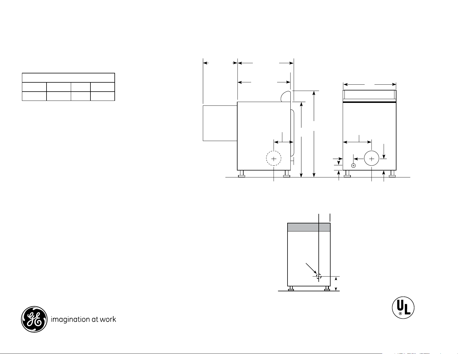
36
25-1/2
42
51
Side View
27
Rear View
36
42
27
2
3-1/2
2-1/2
25-1/2*
Side View
Rear View
8-1/2
28-1/4
23-1/2
11-1/2
*24-1/2" from the edge of the side panel to the front.
25-1/2" from front to edge of endcaps.
5
Back View
Power
Cord Hole
4-1/2
GTDN550ED
GE® 7.0 cu. ft. stainless steel capacity electric dryer with HE Sensor Dry
Dimensions and Installation Information (in inches)
Electric Dryer Rating:
240V
208V
Exhaust Option: 4-way rear, right, left and bottom
Circuit Requirements: An individual, properly-grounded branch circuit,
protected by a 30-amp circuit breaker or a time-delay fuse, is required.
Note: Dryer wall outlet must be located within 36" of service cord entry
and acessible when dryer is mounted in position.
Installation Information: For complete information, see installation
instructions packed with your dryer.
Special Installation Requirements
Alcove or Closet Installation:
• If your dryer is approved for installation in an alcove or closet, it will be stated on a label
on the dryer back.
• The dryer MUST be exhausted to the outside.
• Minimum clearances between dryer cabinet and adjacent walls or other surfaces are:
0" either side; 3" front and rear
• Minimum vertical space from floor to overhead cabinets, ceilings, etc. is 52”.
• Closet doors must be louvered or otherwise ventilated and must contain a minimum
of 60 sq. in. of open area equally distributed. If this closet contains both a washer and
a dryer, doors must contain a minimum of 120 sq. in. of open area equally distributed.
• No other fuel-burning appliance shall be installed in the same closet with a gas dryer.
Bathroom or Bedroom Installation:
• The dryer MUST be exhausted to the outdoors.
• The installation must conform with the local codes, or in the absence of local codes,
with the National Electric Code and National Fuel Gas Code, ANSI Z223 for gas dryers.
Minimum Clearances other than Alcove or Closet Installation:
• Minimum clearances to combustible surfaces are: 0" both sides; 3" rear
Dryer Exhausting Information : Use metal duct only, vertical and horizontal ducting.
5600W 24A 60Hz
4400W 22A 60Hz
For answers to your Monogram,® GE Profile™ or
GE® appliance questions, visit our website at
geappliances.com or call GE Answer Center®
service, 800.626.2000.
Power Cord Locations
Specification Revised 3/14
Listed by
Underwriters
Laboratories
370147
Page 2

GTDN550ED
A
4
GE Dryer Vent
B
2-1/2
GE® 7.0 cu. ft. stainless steel capacity electric dryer with HE Sensor Dry
For complete information, see installation instructions packed with your dryer.
Ducting Materials:
For best performance, this dryer should be vented with 4" diameter all rigid metal
exhaust duct. If rigid metal duct cannot be used, then UL-listed flexible metal (semirigid) ducting can be used (Kit WX08X10077). In special installations, it may be
necessary to connect the dryer to the house vent using a flexible metal (foil-type) duct.
A UL-listed flexible metal (foil-type) duct may be used ONLY in installations where rigid
metal or flexible metal (semi-rigid) ducting cannot be used AND where a 4” diameter
can be maintained throughout the entire length of the transition duct. Please see
installation instruction packed with your dryer for complete instructions when using
flexible metal (foil type) ducting.
Exhaust Length Calculation:
1. Determine the number of 90° turns needed for your installation. If you exhaust to the
side or bottom of dryer, add one turn.
2. The maximum length of 4" rigid (aluminum or galvanized) duct which can be tolerated
is shown in the table. A turn of 45° or less may be ignored. Two 45° turns within the
duct length should be treated as a 90° elbow. A turn over 45° should be treated as a
90° elbow.
Dryers must be exhausted to the outside.
Caution: For personal safety do not terminate exhaust into a chimney, under any
enclosed house floor (crawl space), or into an attic, since the accumulated lint could
create a fire hazard or moisture could cause damage. Never terminate the exhaust
into a common duct or plenum with a kitchen exhaust, since the combination of lint
and grease could create a fire hazard.
Exhaust ducts should be terminated in a dampered wall cap to prevent back drafts,
bird nesting, etc. The wall cap must also be located at least 12" above the ground or
any other obstruction with the opening pointed down.
For more information on venting kits and accessories, please call 1-800-GE-CARES.
Dryer Exhausting Information — Use Metal Duct Only
Vertical and Horizontal Ducting
Best performance
A
Number
Domestic dryer models
All Long Vent 6.0 - 8.3 cu. ft.
capacity electric & gas dryers
(GTDL, GFDL)
All 6.0 - 8.3 cu. ft. capacity
models electric and gas dryers
(GFDS, GFDR, GFDN, GTDS,
GTDN, GHDN, GHDS, GTDP,
GLDP, GTDX, HTDP, HTDX)
DCVH480
All 3.6 cu. ft. (DSKS, DSKP)
electric dryers
Laundry Center GTUP270,
GTUN275
Laundry Center GTUP240
For every extra 90° elbow, reduce the allowable vent system
length by 10 ft.
Two 45° elbows will be treated like one 90° elbow.
For the side exhaust installations, add one 90° elbow to
the chart.
The total vent system length includes all the straight
portions and elbows of the system (transition duct included).
Laundry Center length includes factory-installed elbow that
does not impact vent length.
Maximum length
of 4" dia rigid
metal duct
Exhaust hood type
of 90°
turns
0 150 ft. 125 ft.
1 135 f t. 115 ft.
2 125 ft. 105 ft.
3 115 ft. 95 ft.
4 105 f t. 85 ft.
5 95 ft. 75 ft.
0 90 ft. 60 ft.
1 60 ft. 45 ft.
2 45 ft . 35 ft.
3 35 ft. 25 ft.
4 25 ft. 15 f t.
0 90 ft. 60 ft.
1 60 ft. 45 ft.
2 45 ft . 35 ft.
3 35 ft. 25 ft.
0 46 ft. 37 ft.
1 37 ft. 30 ft.
2 30 ft. 22 ft.
3 23 ft. 15 ft.
0 56 ft. 42 ft.
1 48 ft. 34 ft.
2 40 ft. 26 ft.
3 32 ft. 18 ft.
0 43 ft. 36 ft.
1 33 ft . 26 ft.
2 24 f t. 16 ft.
A
4"
opening
B
2-1 /2"
opening
Specification Revised 3/14
370147
Page 3

GTDN550ED
GE® 7.0 cu. ft. stainless steel capacity electric dryer with HE Sensor Dry
Features and Benefits
• HE Sensor Dry - Keep your clothes looking and feeling their best. Dual
thermistors continually monitor temperature with a sensor bar that
measures moisture to prevent over-drying
• LED electronic controls with cycle countdown display show exactly
how much time is left for each cycle
• eMonitor - an electronic readout shows the exact efficiency of each
cycle so the user can decide how they want to dry each load
• eDry option—energy-saving option reduces dry temperatures on
select cycles without sacrificing performance
• 5 heat selections provide the right temperatures for your clothes-
drying needs
• Quick Fluff delivers ready-to-go results in minutes without heat
• Variable end-of-cycle signal—adjustable volume offers added
flexibility
• Delicate cycle helps protect delicate fabrics
• Model GTDN550EDWW –White
Specification Revised 3/14
370147
 Loading...