

Page 1
GTD42EASJ
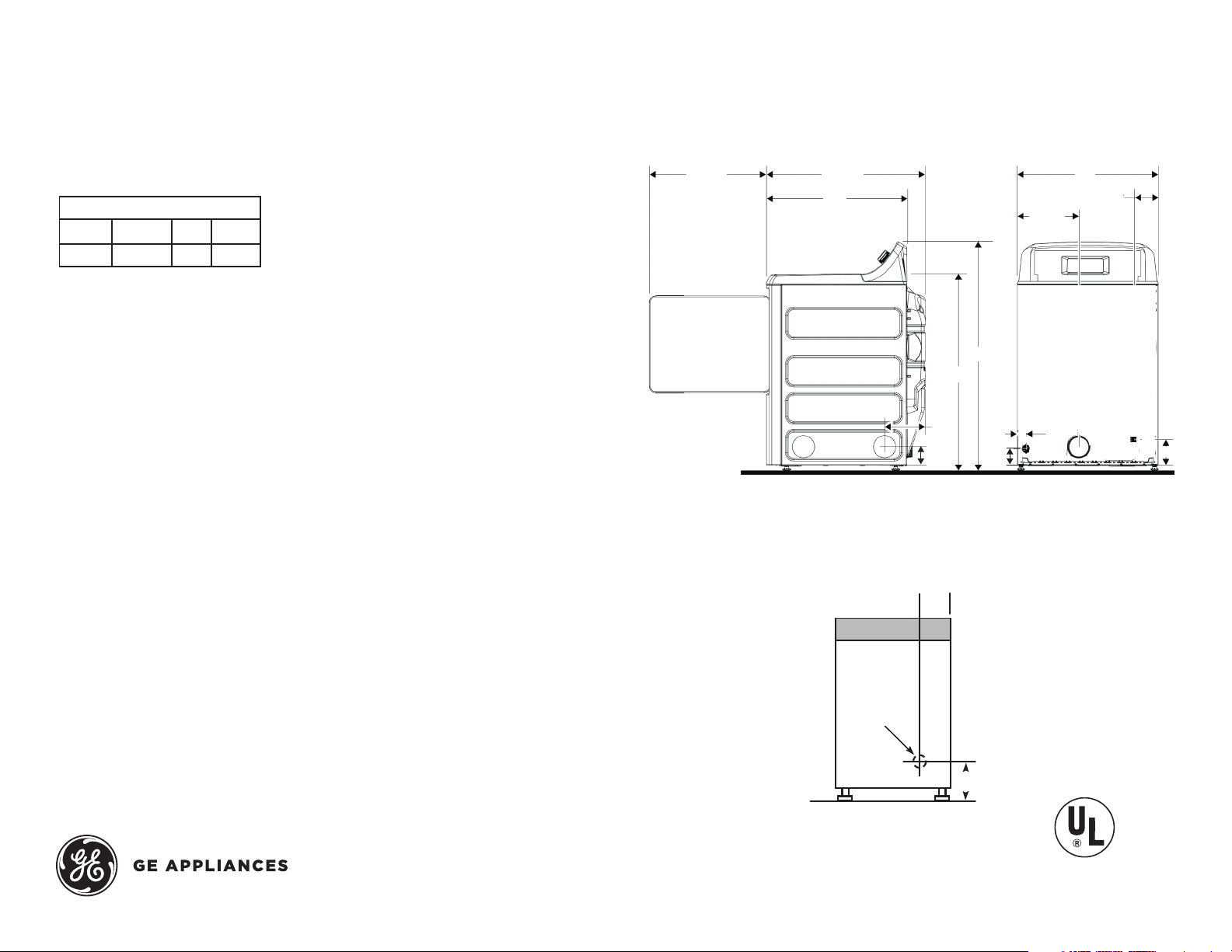
22 1/2"
29 1/2"
26"
3 1/2"
1 3/4"
3 1/4"
8"
37 1/2"
44"
27"
5"
Power Cord 4 1/2"
11 3/4"
5
Power
Cord Hole
4-1/2
GE® Series 7.2 Cu. Ft. Capacity Electric Dryer
dimensions and instaLLation information
(in inChes)
eLeCtriC dryer rating:
240V 5600W 24A 60Hz
208V 4400W 22A 60Hz
exhaust oPtion: 4-way rear, right, left and bottom.
CirCuit requirements: An individual, properly-grounded branch circuit,
protected by a 30-amp circuit breaker or a time-delay fuse, is required.
note: Dryer wall outlet must be located within 36" of service cord entry and
acessible when dryer is mounted in position.
instaLLation information : For complete information, see installation
instructions packed with your dryer.
sPeCiaL instaLLation requirements
aLCoVe or CLoset instaLLation:
- If your dryer is approved for installation in an alcove or closet, it will be stated
on a label on the dryer back.
- The dryer MUST be exhausted to the outside.
- Minimum clearances between dryer cabinet and adjacent walls or other surfaces
are: 0" either side; 3" front and rear.
- Minimum vertical space from floor to overhead cabinets, ceilings, etc. is 52".
- Closet doors must be louvered or otherwise ventilated and must contain a minimum
of 60 sq. in. of open area equally distributed. If this closet contains both a washer
and a dryer, doors must contain a minimum of 120 sq. in. of open area equally distributed.
- No other fuel-burning appliance shall be installed in the same closet with a gas dryer.
Bathroom or Bedroom instaLLation:
- The dryer MUST be exhausted to the outdoors.
- The installation must conform with the local codes, or in the absence of local codes,
with the National Electric Code and National Fuel Gas Code, ANSI Z223 for gas dryers.
minimum CLearanCes other than aLCoVe or CLoset instaLLation:
- Minimum clearances to combustible surfaces are: 0" both sides; 3" rear.
dryer exhausting information : Use metal duct only, vertical and horizontal ducting.
For answers to your Monogram, GE Profile™ Series
or GE® Series appliance questions, visit our website
at geappliances.com or call GE Answer Center®
service, 800.626.2000.
side View rear View
Power Cord LoCations
BaCk View
Speci fication Revised 10/15
Listed by
Underwriters
Laboratories
Page 2
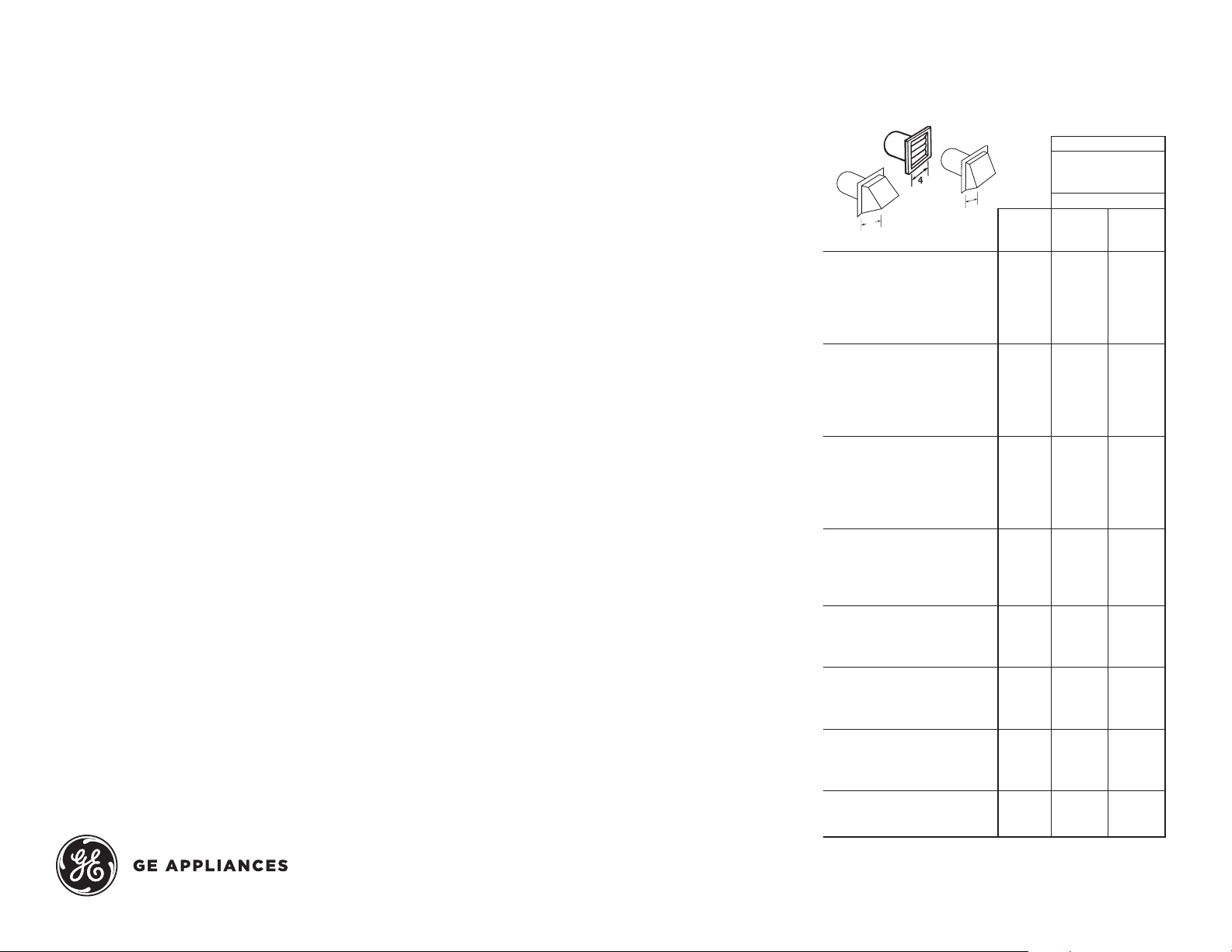
A
B
4
GE Dryer Vent
B
2-1/2
GTD42EASJ
GE® Series 7.2 Cu. Ft. Capacity Electric Dryer
for ComPLete information, see instaLLation instruCtions
PaCked with your dryer.
duCting materiaLs:
For best performance, this dryer should be vented with 4" diameter all rigid metal
exhaust duct. If rigid metal duct cannot be used, then UL-listed flexible metal
(semi-rigid) ducting can be used (Kit WX08X10077). In special installations, it
may be necessary to connect the dryer to the house vent using a flexible metal
(foil-type) duct. A UL-listed f lexible metal (foil-type) duct may be used ONLY in
installations where rigid metal or flexible metal (semi-rigid) ducting cannot be
used AND where a 4" diameter can be maintained throughout the entire length
of the transition duct. Please see installation instruction packed with your dryer
for complete instructions when using flexible metal (foil type) ducting.
exhaust Length CaLCuLation:
1. Determine the number of 90° turns needed for your installation. If you exhaust
to the side or bottom of dryer, add one turn.
2. The maximum length of 4" rigid (aluminum or galvanized) duct which can be
tolerated is shown in the table. A turn of 45° or less may be ignored. Two 45°
turns within the duct length should be treated as a 90° elbow. A turn over 45°
should be treated as a 90° elbow.
Dryers must be exhausted to the outside.
Caution: For personal safety do not terminate exhaust into a chimney, under
any enclosed house f loor (crawl space), or into an attic, since the accumulated
lint could create a fire hazard or moisture could cause damage. Never terminate
the exhaust into a common duct or plenum with a kitchen exhaust, since the
combination of lint and grease could create a fire hazard.
Exhaust ducts should be terminated in a dampered wall cap to prevent back
drafts, bird nesting, etc. The wall cap must also be located at least 12" above
the ground or any other obstruction with the opening pointed down.
for more information on Venting kits and aCCessories,
PLease CaLL 1-800-ge-Cares.
For answers to your Monogram, GE Profile™ Series
or GE® Series appliance questions, visit our website
at geappliances.com or call GE Answer Center®
service, 800.626.2000.
dryer exhausting information—use metaL
duCt onLy VertiCaL and horizontaL duCting
BEST PERFORMANCE
A
Number
of 90°
Domestic dryer models
GE Front Load Long Vent 7.0
cu. ft. capacity electric dryer
(GF DL)
Long Vent 6.1-7.4 cu. ft.
capacity electric & gas
(GTD42, GTD45, GTD65,
GTX42 and GTX65
Long Vent 61 -7.4 cu. ft.
capacity electric & gas
(GTD42, GTD45, GTD65,
GTX42 and GTX60)
All 6.0 - 8 .3 cu. ft. capacity
models electric and gas dryers
(GFDS, GFDR, G FDN, GTDS,
GTDN, GHDN , GHDS, GTDP,
GLDP, GTD, HTDP, HTDX)
DCVH480
All 3.6 cu. ft. (DSKS, DSKP)
electric dryers
Laundry Center GUD27
Laundry Center GUD24
Maximum length
of 4" dia rigid
metal duct
Exhaust hood t ype
A
4"
turns
opening
0 200 ft. 175 ft.
1 185 f t. 165 ft.
2 175 ft. 155 ft.
3 165 ft. 145 ft.
4 155 ft. 135 ft.
5 145 ft. 125 ft.
0 150 ft. 125 ft.
1 135 ft. 115 ft.
2 125 ft. 105 ft.
3 115 f t. 95 ft.
4 105 ft. 85 ft.
5 95 f t. 75 ft.
0 120 ft. 90 ft.
1 100 ft. 75 ft.
2 85 f t. 65 ft.
3 70 ft. 55 ft.
4 60 ft. 45 ft.
5 55 f t. 35 ft.
0 90 ft. 60 ft.
1 60 ft. 45 ft.
2 45 ft. 35 ft.
3 35 f t. 25 ft.
4 25 ft. 15 ft.
0 90 ft. 60 ft.
1 60 ft. 45 ft.
2 45 ft. 35 ft.
3 35 f t. 25 ft.
0 46 ft. 37 f t.
1 37 ft. 30 ft.
2 30 ft. 22 ft.
3 23 f t. 15 ft.
0 56 ft. 42 ft.
1 48 ft. 34 ft.
2 40 ft. 26 ft.
3 32 f t. 18 ft.
0 43 ft. 36 f t.
1 33 ft. 26 f t.
2 24 f t. 16 ft.
Speci fication Revised 10/15
opening
B
2-1/2"
Page 3

GTD42EASJ
GE® Series 7.2 Cu. Ft. Capacity Electric Dryer
features and Benefits
Auto Dry – For clothes that come out feeling and looking great, this setting
monitors air temperature to set the optimal drying time
WrinkleCare Extended Tumble – Reduces wrinkling and creasing
End-of-Cycle Signal – Alerts you when the load is done, so clothes can be
removed before wrinkles set in
4 heat selections – Provide the right temperatures for your clothes-drying needs
Up to 120-ft. venting capability – Provides f lexible installation
Model GTD42EASJWW – White
Speci fication Revised 10/15
 Loading...