

GE GTD18ESSJ2WW, GTD18GSSJ2WW, GTD42EASJ0WW, GTD42EASJ1WW, GTD42GASJ0WW Installation Guide
...Page 1
Installati
n
Dryers
Instructi
i Ouestions? Call800.GE.CARES {800.432.2737)orvisitour Web siteat:GEAppliances.com i
This isthe safety alert symbol. This symbol alerts you to potential hazards that can kill you or hurt you and others.
A
All safety messages will follow the safety alert symbol and the word "DANGER","WARNING", or "CAUTION".These
words are defined as:
Indicates a hazardoussituation which, if not avoided,will resultin death or seriousinJury.
Indicates a hazardoussituation which, if not avoided, could result indeath or seriousinjury.
Indicates a hazardoussituation which, if not avoided, could result inminor or moderate injury.
BEFORE YOU BEGIN
Readthese instructions completely and carefully.
• IMPORTANT-save these instructions for local
electrical inspector's use.
• IMPORTANT- Observeallgoverning codesand
ordinances.
• Installthe clothes dryer according to the manufacturer's
instructions and local codes.
• Note to Installer - Be sure to leavethese instructions
with the Consumer.
• Note to Consumer - Keepthese instructions for future
reference.
• Clothes dryer installation must be performed by a
qualified installer.
• Thisdryer must be exhausted to the outdoors.
• Before the old dryer is removed from service or
discarded, remove the dryer door.
• Service information and the wiring diagram are located
in the control console.
• Do not allow children on or inthe appliance. Close
supervision of children isnecessary when the appliance
is used near children.
• Proper installation isthe responsibility of the installer.
• Product failure due to improper installation is not
covered under the Warranty.
• Install the dryer where the temperature is above 50°F
for satisfactory operation of the dryer control system.
• Remove and discard existing plastic or metal foil duct
and replace with UL-listed duct.
as
- Fire Hazard
• Clothes dryer installation must be performed by a
qualified installer.
Install the clothes dryer according to these
instructions and local codes.
DO NOT install a clothes dryer with flexible plastic
venting materials. If flexible metal (semi-rigid or
foil-type) duct is installed, it must be UL-listed and
installed in accordance with the instructions found
in "Connecting the Dryer to House Vent" later in
this manual. Flexible vent materials are known to
collapse, be easily crushed and trap lint. These
conditions will obstruct dryer airflow and increase
the risk of fire.
DO NOT install or store this appliance in any
location where it could be exposed to water or
weather.
To reduce the risk of severe injury or death, follow
all installation instructions.
Save these instructions. (Installers: Be sure to leave
these instructions with the customer.)
01
Printed in Me×ico
234D2318P001
31-16767-Io5-15GE
Page 2
Installation Instructions
StateofCaliforniaProposition65 Warnings:
TheCaliforniaSafeDrinkingWater and Toxic EnforcementAct requiresthe governor of Californiato publisha list of substances
known to the state to cause cancer, birth defects or other reproductive harm and requiresbusinessesto warn of potential exposure
to suchsubstances.
Thisproduct contains one or morechemicals known to the Stateof Californiato causecancer, birth defectsor
other reproductive harm.
Gasappliances cancause low-level exposureto some ofthese substances,including benzene,carbon monoxide, formaldehyde and
soot,caused primarily by the incompletecombustion of natural gas or LPfuels. Exposureto these substancescan be minimized by
properlyventing the dryer to the outdoors.
UNPACKING YOUR DRYER
Tilt the dryer sideways and remove the foam
shipping pads by pulling at the sides and breaking
them away from the dryer legs. Be sure to remove all
of the foam pieces around the legs.
Remove literature and bag containing accessories.
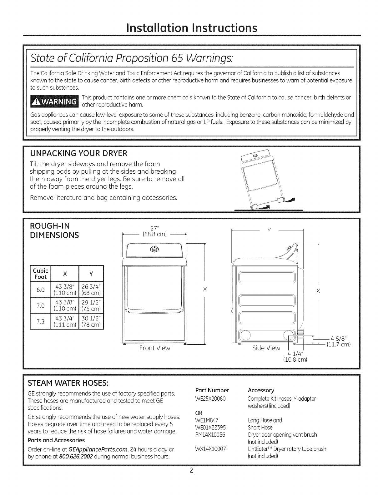
ROUGH-IN 27"
DIMENSIONS ------ (68.8 cm)
Cubic × y
Foot
43 3/8" 26 3/4"
6.0 (110 cm) (68 cm)
43 3/8" 29 1/2"
7.0 (110 cm) (75 cm)
43 3/4" 30 1/2"
7.3 (111cm) (78 cm)
Front View
J
STEAM WATER HOSES:
GEstrongly recommends the useof factory specified parts.
Thesehosesare manufactured andtested to meet GE
specifications.
GEstrongly recommends the useof new water supply hoses.
Hosesdegrade overtime and need to bereplaced every 5
years to reducethe risk of hose failures and water damage.
Parts end Accessories
Order on-line at GEAppliencePorts.com, 24 hours a day or
by phone at 800.626.2002during normal businesshours.
Pert Number
WE25X20060
OR
WEltq847
WE01X22395
plVll4X100%
WX14X10007
Y
.................. -4--
%
Side View \_
4 1/4"
(10.8cm)
Accessory
CompleteKit(hoses,Y-adapter
washers)(included)
LongHoseand
ShortHose
Dryerdooropeningventbrush
(notincluded)
LintEaterTM Dryerrotarytube brush
(notincluded)
X
_14 s/8"
1.7 cm)
Page 3
Installation Instructions
REQUIREMENTS FOR ALCOVE OR
CLOSET INSTALLATION
_- Explosion Hazard
Keepflammable materials and vapors, such as gasoline,
away from dryer.
Placedryer at least 18" (/46cm) above the floor for a
garage installation.
Failureto do so can result in death, explosion, or fire.
,, If the dryer is approved for installation in an alcove or
closet, it will be stated on a label on the dryer back.
• The dryer MUST be vented to the outdoors. See
the EXHAUSTING THE DRYERsection.
• Minimum clearance between dryer cabinet and
adjacent walls or other surfaces is:
0" either side
3" front
0" rear but a 1" minimum is recommended
Minimum vertical space from dryer to overhead
shelves, cabinets, ceilings, etc., is 1" on top.
Consideration must be given to provide adequate
clearance for installation and service.
Closet doors must be Iouvered or otherwise
ventilated and have at least 60 square inches of
open area. If the closet contains both a washer
and a dryer, doors must contain a minimum of
120 square inches of open area.
NOTE: WHEN THE EXHAUST DUCT IS LOCATED IN
THE REAR OF THE DRYER,THE CONFIGURATION OF
THE DUCTING MAY REQUIRE GREATER THAN 0" OF
REARCLEARANCE.A 1" MINIMUM ISRECOMMENDED.
Gas Dryers Only:
• No other fuel burning appliance shall be installed
in the same closet as a gas dryer.
The dryer must be disconnected from the gas
supply piping during pressure testing at pressures
greater than 1_ psi (3.5 kPa).
A 1/8 inch NPT minimum plugged tapping,
accessible for test gauge connection, must be
installed immediately upstream of the gas supply
connection to the dryer.
MINIMUM CLEARANCE OTHER THAN
ALCOVE OR CLOSET INSTALLATION
Minimum clearance to combustible surfaces and
for air opening are: 0" both sides; 1" front; 0" rear
but a 1" minimum is recommended. Consideration
must be given to provide adequate clearance for
installation and service.
MOBILE OR MANUFACTURED HOME
INSTALLATION
• Installation must conform to the
MANUFACTURED HOME CONSTRUCTION AND
SAFETYSTANDARD, TITLE 2/4, PART 32-80 or
Standard CAN/CSA-Z240 MH, or, when such
standard is not applicable, with AMERICAN
NATIONAL STANDARD FOR MOBILE HOME,
ANSI/NFPA NO. 501B.
The dryer MUST be vented to the outdoors. The
exhaust vent must be securely fastened to a
non-combustible portion of the mobile home.
The vent MUST NOT be terminated beneath a
mobile or manufactured home.
• The vent duct material MUST BE METAL.
• KIT 14-D346-33 MUST be used to attach the dryer
securely to the structure.
• The vent MUST NOT be connected to any other
duct, vent or chimney.
• Do not use sheet metal screws or other
fastening devices which extend into the interior
of the exhaust vent.
• Provide an opening with a free area of at least
25 square inches for introduction of outside air
into the dryer room.
• See the sections for electrical connection
information.
POWER CORDS:
GEstrongly recommends the useof factory specified parts.
Selectthe power cord to fit your installation requirements.
Order on-line at GEApplianceParts.com, 24 hours a day or
by phone at 800.626.2002during normal businesshours.
Part Number Type Length Amperage
WX9X2 ]5-Prong 4 Feet 30
WX9X3 3-Prong 5 Feet 30
WX9X4 3-Prong 6 Feet 30
WX9X!8 4-Prong 4 Feet 30
WX9X!9 4-Prong 5 Feet 30
WX9X20 4-Prong 6 Feet 30
Page 4
Installation Instructions
CONNECTING INLET HOSES
CONNECTING INLET HOSES
(on some models)
To produce steam, the dryer must connect to
the cold water supply. Since the washer must
also connect to the cold water, a "Y" connector
is inserted to allow both inlet hoses to make that
connection at the same time.
NOTE: Use the new inlet hoses provided; never use
old hoses.
,
Turn the cold water faucet off. Remove the
washer inlet hose from the washer fill valve
connector (cold).
.
Ensure the rubber flat washer is in place and
attach one female coupling of the short hose
onto the washer fill valve connector. Tighten by
hand until firmly seated.
.
Attach one male end of the "Y" connector to the
other female coupling of the short hose. Ensure
the rubber flat washer is in place. Tighten by
hand until firmly seated.
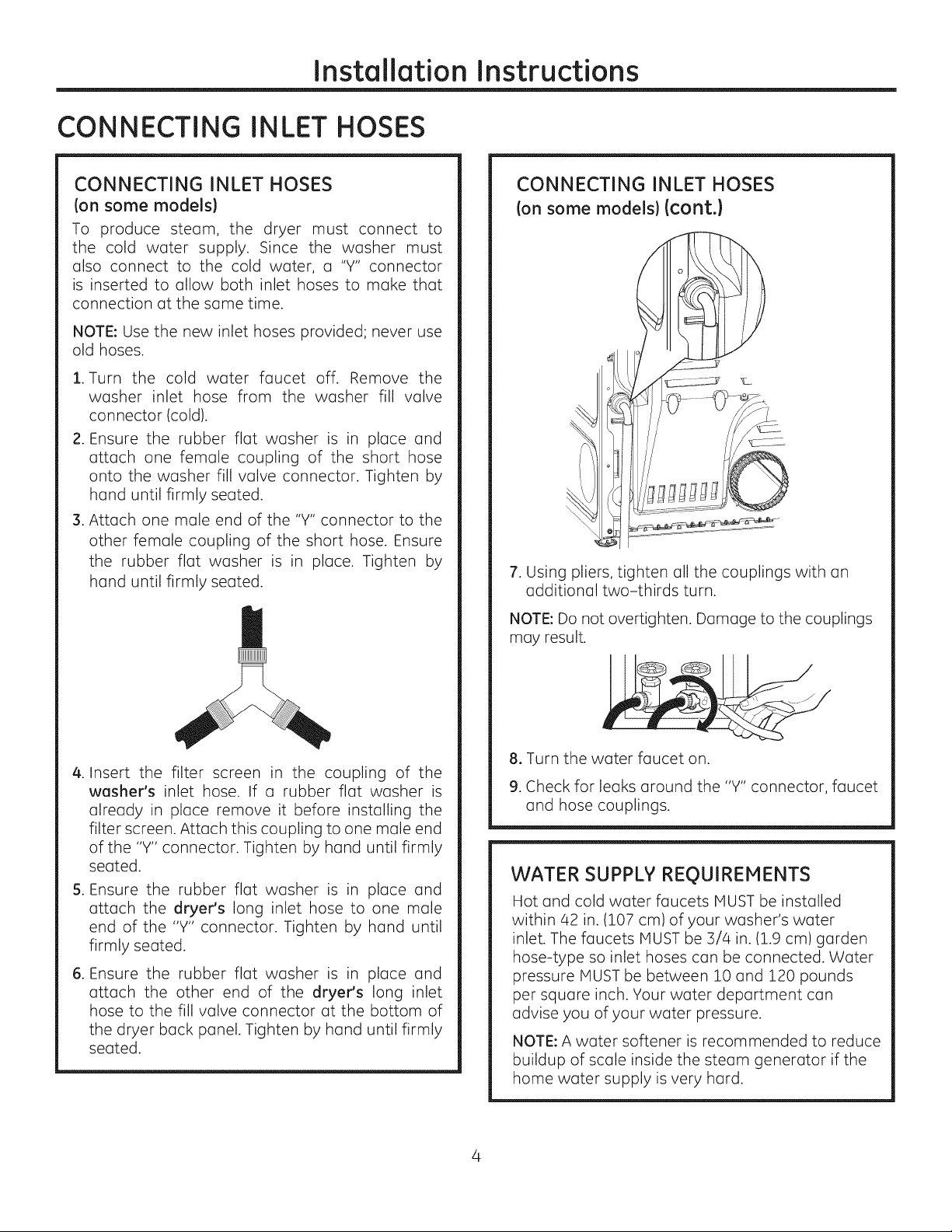
CONNECTING INLET HOSES
Ion some models)(cont.}
7. Using pliers, tighten all the couplings with an
additional two-thirds turn.
NOTE: Do not overtighten. Damage to the couplings
may result.
.
Insert the filter screen in the coupling of the
washer's inlet hose. If a rubber flat washer is
already in place remove it before installing the
filter screen. Attach this coupling to one male end
of the "Y" connector. Tighten by hand until firmly
seated.
S.
Ensure the rubber flat washer is in
attach the dryer's long inlet hose to
end of the "Y" connector. Tighten by
place and
one male
hand until
firmly seated.
.
Ensure the rubber flat washer is in
attach the other end of the dryer's
hose to the fill valve connector at the
the dryer back panel. Tighten by hand
place and
long inlet
bottom of
until firmly
seated.
8. Turn the water faucet on.
9. Check for leaks around the "Y" connector, faucet
and hose couplings.
WATER SUPPLY REQUIREMENTS
Hot and cold water faucets MUST be installed
within 42 in. (107 cm) of your washer's water
inlet. The faucets MUST be 3/4 in. (1.9 cm) garden
hose-type so inlet hoses can be connected. Water
pressure MUST be between 10 and 120 pounds
per square inch. Your water department can
advise you of your water pressure.
NOTE: A water softener is recommended to reduce
buildup of scale inside the steam generator if the
home water supply is very hard.
Page 5
Installation Instructions
CONNECTING A GAS DRYER(ski
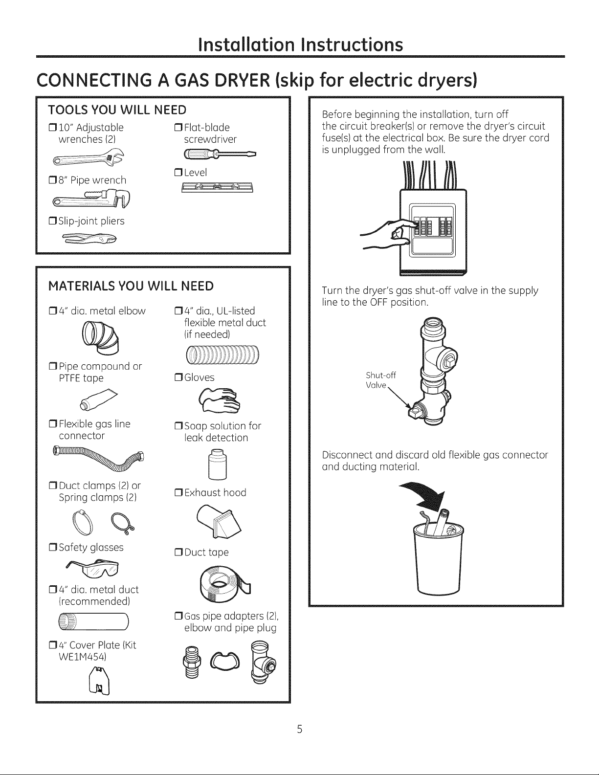
TOOLS YOU WILL NEED
010" Adjustable 0 Flat-blade
wrenches (2) screwdriver
17Level
178" Pipe wrench
17Slip-joint pliers
MATERIALS YOU WILL NEED
174" dia. metal elbow
174" dia., UL-listed
flexible metal duct
(if needed)
) for electric dryers}
Before beginning the installation, turn off
the circuit breaker(s) or remove the dryer's circuit
fuse(s) at the electrical box. Be sure the dryer cord
is unplugged from the wall.
Turn the dryer's gas shut-off valve in the supply
line to the OFF position.
17Pipe compound or
PTFEtape
13Flexible gas line
connector
17Duct clamps (2) or
Spring clamps (2)
%
0 Safety glasses
174" dia. metal duct
(recommended)
)
174" Cover Plate (Kit
WE1H454)
17Gloves
17Soap solution for
leak detection
0 Exhaust hood
17Duct tape
17Gas pipe adapters (2),
elbow and pipe plug
@o
Shut-off
Valve
Disconnect and discard old flexible gas connector
and ducting material.
Page 6
Installation Instructions
CONNECTING A GAS DRYER(ski
GAS REQUIREMENTS
_ Explosion Hazard
Use a new CSA International approved flexible
gas supply line. Never reuse old flexible
connectors.
o
Install a shut-off valve.
o
Securely tighten all gas connections.
o
If connected to LPgas, have a qualified person
make sure gas pressure does not exceed 13"
water column.
• Examples of a qualified person include: licensed
heating personnel, authorized gas company
personnel, and authorized service personnel.
Failure to do so can result in death, explosion,
or fire.
This gas dryer is equipped with a valve and
burner assembly for use only with natural gas.
Using conversion kit WE2SX217,your local service
organization can convert this dryer for use with
propane (LP)gas. (To convert from propane (LP)
to natural gas, conversion kit WE25X218 will be
utilized.) ALL CONVERSIONS MUST BE MADE BY
PROPERLYTRAINED AND QUALIFIED PERSONNEL
AND IN ACCORDANCEWITH LOCALCODESAND
ORDINANCE REQUIREMENTS.
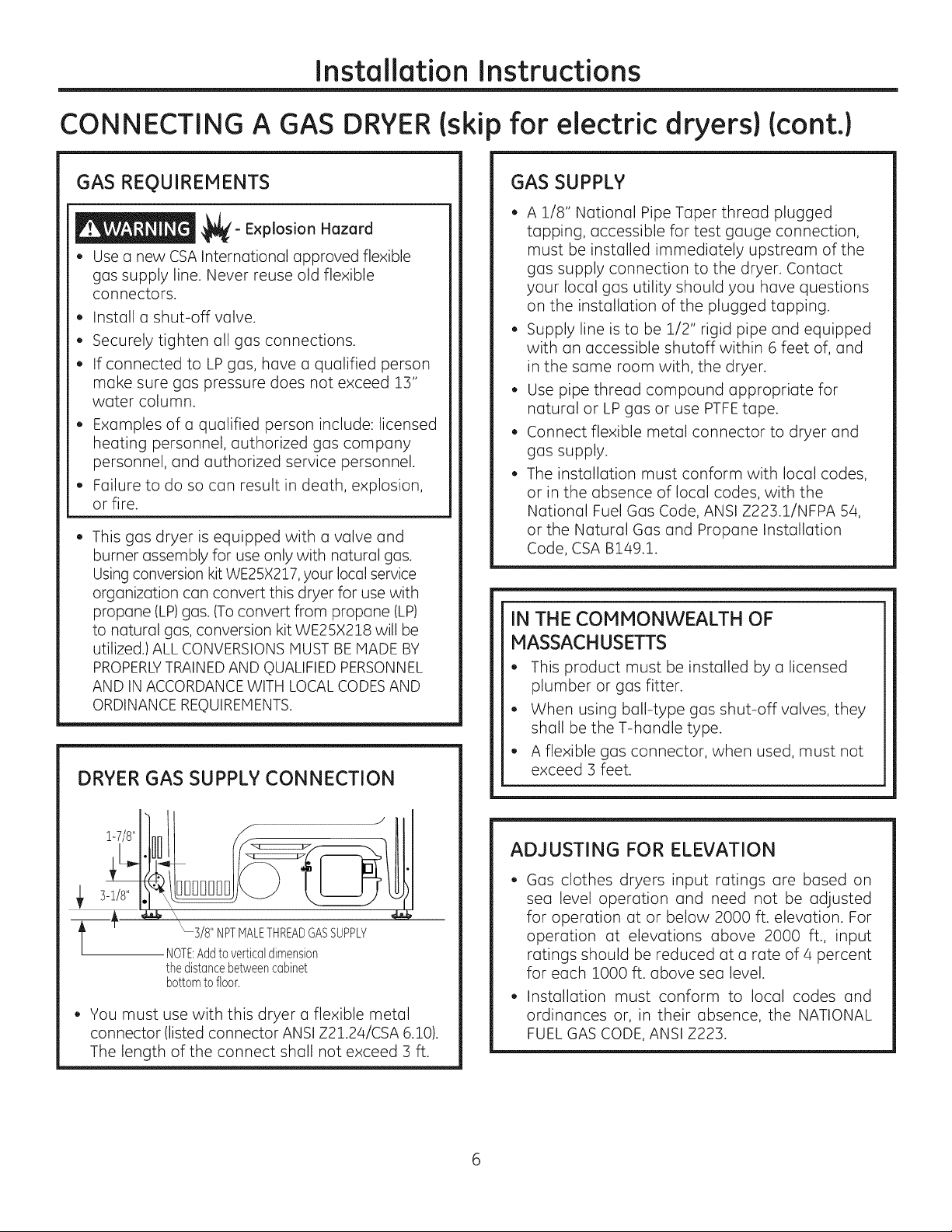
DRYER GAS SUPPLY CONNECTION
for electric dryers)(cont.)
GAS SUPPLY
A 1/8" National Pipe Taper thread plugged
tapping, accessible for test gauge connection,
must be installed immediately upstream of the
gas supply connection to the dryer. Contact
your local gas utility should you have questions
on the installation of the plugged tapping.
Supply line is to be 1/2" rigid pipe and equipped
with an accessible shutoff within 6 feet of, and
in the same room with, the dryer.
Use pipe thread compound appropriate for
natural or LP gas or use PTFEtape.
Connect flexible metal connector to dryer and
gas supply.
The installation must conform with local codes,
or in the absence of local codes, with the
National Fuel Gas Code, ANSI Z223.1/NFPA 54,
or the Natural Gas and Propane Installation
Code, CSA B149.1.
IN THE COMMONWEALTH OF
MASSACHUSETTS
This product must be installed by a licensed
plumber or gas fitter.
When using ball-type gas shut-off valves, they
shall be the T-handle type.
A flexible gas connector, when used, must not
exceed 3 feet.
1-7/8"
3-1/8"
3/8"NPTMALETHREADGASSUPPLY
NOTE:Addtoverticabdimension
thedistancebetweencabinet
bottomtofloor.
You must use with this dryer a flexible metal
connector (listed connector ANSI Z21.24/CSA 6.10).
The length of the connect shall not exceed 3 ft.
ADJUSTING FOR ELEVATION
Gas clothes dryers input ratings are based on
sea level operation and need not be adjusted
for operation at or below 2000 ft. elevation. For
operation at elevations above 2000 ft., input
ratings should be reduced at a rate of 4 percent
for each 1000 ft. above sea level.
Installation must conform to local codes and
ordinances or, in their absence, the NATIONAL
FUEL GAS CODE, ANSI Z223.
Page 7
Installation Instructions
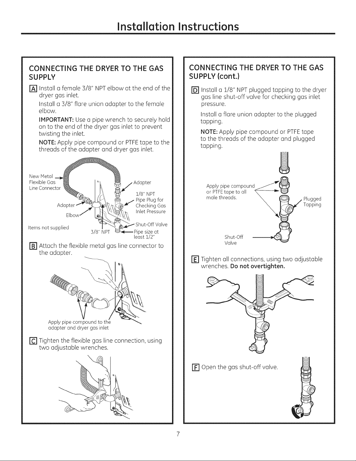
CONNECTING THE DRYER TO THE GAS
SUPPLY
Install a female 3/8" NPT elbow at the end of the
@
dryer gas inlet.
Install a 3/8" flare union adapter to the female
elbow.
IMPORTANT: Use a pipe wrench to securely hold
on to the end of the dryer gas inlet to prevent
twisting the inlet.
NOTE: Apply pipe compound or PTFEtape to the
threads of the adapter and dryer gas inlet.
New Metal
Flexible Gas _
LineConnector ___. _
AdGpter_ _ _
Elbow _
Items not supplied
r_ Attach the flexible metal gas line connector to
the adapter.
3/8" NPT
_pj Adapter
1/8" NPT
Pipe Plug for
Checking Gas
Inlet Pressure
Shut-Off Valve
ipe size at
least !/2"
CONNECTING THE DRYERTO THE GAS
SUPPLY(cont.)
@Install a 1/8" NPT plugged tapping to the dryer
gas line shut-off valve for checking gas inlet
pressure.
Install a flare union adapter to the plugged
tapping.
NOTE: Apply pipe compound or PTFEtape
to the threads of the adapter and plugged
tapping.
oArPPITYFPitPe;°tm Pa_und_@
male threads. __ W PlaUp_1_dg
r_ Tighten all connections, using two adjustable
wrenches. Do not overtighten.
Apply pipe compound to the
adapter and dryer gas inlet
r_ Tighten the flexible gas line connection, using
two adjustable wrenches.
\
EF1Open the gas shut-off valve.
Page 8
Installation Instructions
CONNECTING A GAS DRYERIskip for electric dryers)Icont.)
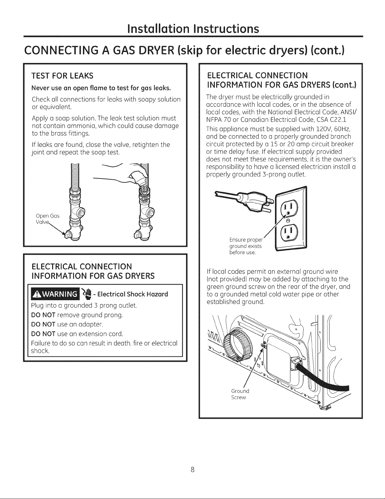
TEST FOR LEAKS
Never use an open flame to test for gas leaks.
Check all connections for leaks with soapy solution
or equivalent.
Apply a soap solution. The leak test solution must
not contain ammonia, which could cause damage
to the brass fittings.
If leaks are found, close the valve, retighten the
joint and repeat the soap test.
Open Gos
ELECTRICAL CONNECTION
INFORMATION FOR GAS DRYERS {cont.}
The dryer must be electrically grounded in
accordance with local codes, or in the absence of
local codes, with the National Electrical Code, ANSI/
NFPA 70 or Canadian Electrical Code, CSA C22.1
This appliance must be supplied with 120V, 60Hz,
and be connected to a properly grounded branch
circuit protected by a 15 or 20 amp circuit breaker
or time delay fuse. If electrical supply provided
does not meet these requirements, it is the owner's
responsibility to have a licensed electrician install a
properly grounded 3-prong outlet.
Ensure proper
ground exists
before use.
ELECTRICAL CONNECTION
INFORMATION FOR GAS DRYERS
_,dL
_ - Electrical Shock Hazard
i
Plug into a grounded 3 prong outlet.
DO NOT remove ground prong.
DO NOT use an adapter.
DO NOT use an extension cord.
Failure to do so can result in death, fire or electrical
shock.
If local codes permit an external ground wire
(not provided) may be added by attaching to the
green ground screw on the rear of the dryer, and
to a grounded metal cold water pipe or other
established ground.
Ground
Screw
Page 9
Instollotion Instructions
CONNECTING AN ELECTRIC DRYER
(Skip for gos dryers ond if your dryer olreody hos o power cord ottoched)
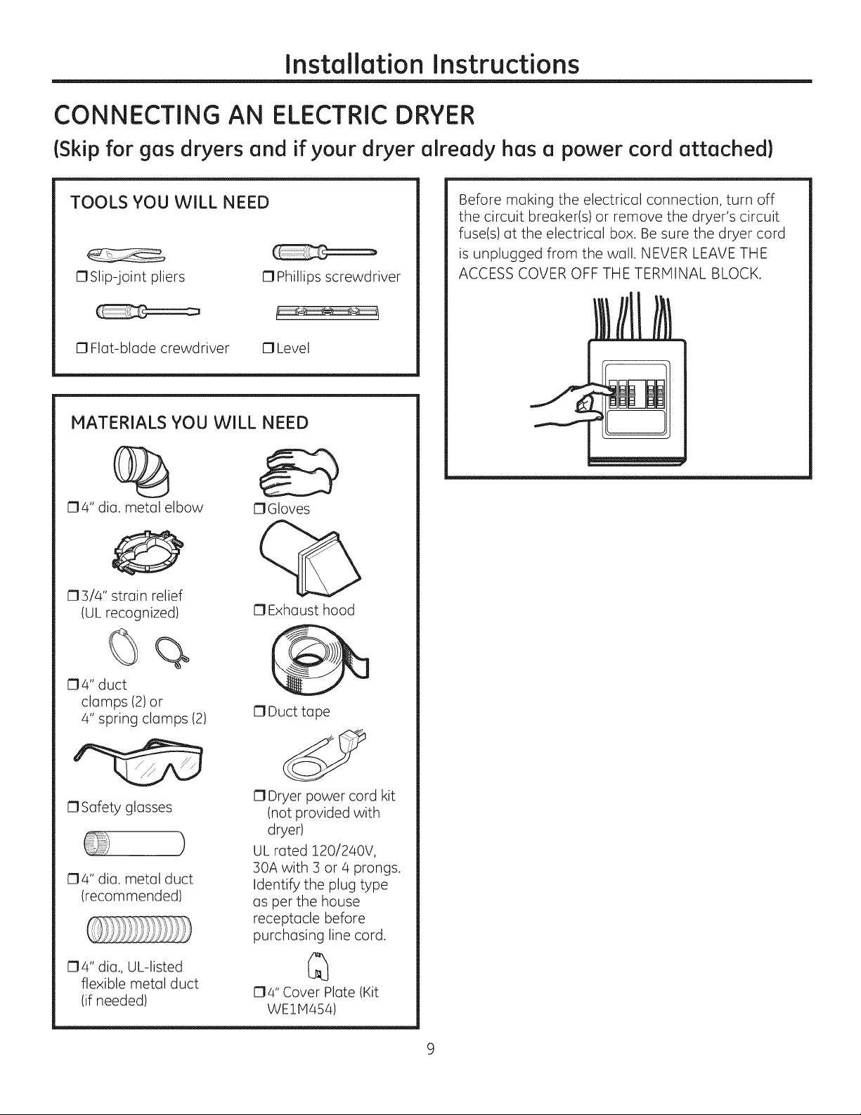
TOOLS YOU WILL NEED
OSlip-joint pliers 0 Phillips screwdriver
0 Flat-blade crewdriver 0 Level
MATERIALS YOU WILL NEED
04" dia. metal elbow
03/4" strain relief
IUL recognized)
OGIoves
O Exhaust hood
Before making the electrical connection, turn off
the circuit breaker(s) or remove the dryer's circuit
fuse(s) at the electrical box. Be sure the dryer cord
is unplugged from the wall. NEVER LEAVE THE
ACCESS COVER OFF THE TERMINAL BLOCK.
O4" duct
clamps (2)or
4" spring clamps (2)
0 Safety glasses
04" dia. metal duct
(recommended)
O4" dia., UL-listed
flexible metal duct
(if needed)
0 Duct tape
O Dryer power cord kit
(not provided with
dryer)
)
UL rated 120/240V,
30A with 3 or 4 prongs.
Identify the plug type
as per the house
receptacle before
purchasing line cord.
O4" Cover Plate (Kit
WE1H454)
Page 10
InstallationInstructions
CONNECTING AN ELECTRIC DRYER {cont.}
{Skipforgas dryersand ifyour dryeralreadyhas a power cord attached}
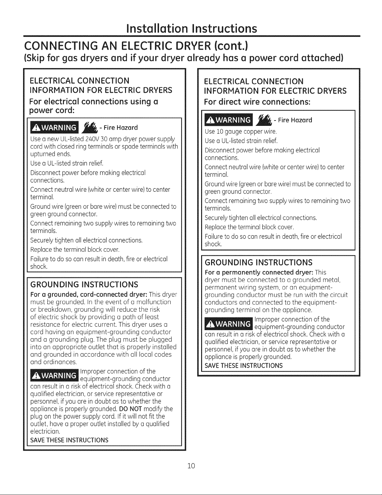
ELECTRICAL CONNECTION
INFORMATION FOR ELECTRIC DRYERS
For electrical connections using a
power cord:
- Fire Hazard
Use a new UL-listed 240V 30 amp dryer power supply
cord with closed ring terminals or spade terminals with
upturned ends.
Use a UL-listed strain relief.
Disconnect power before making electrical
connections.
Connect neutral wire (white or center wire) to center
terminal.
Ground wire (green or bare wire) must be connected to
green ground connector.
Connect remaining two supply wires to remaining two
terminals.
Securely tighten all electrical connections.
Replace the terminal block cover.
Failure to do so can result in death, fire or electrical
shock.
GROUNDING INSTRUCTIONS
For a grounded, cord-connected dryer: This dryer
must be grounded. In the event of a malfunction
or breakdown, grounding will reduce the risk
of electric shock by providing a path of least
resistance for electric current. This dryer uses a
cord having an equipment-grounding conductor
and a grounding plug. The plug must be plugged
into an appropriate outlet that is properly installed
and grounded in accordance with all local codes
and ordinances.
Improper connection of the
equipment-grounding conductor
can result in a risk of electrical shock. Check with a
qualified electrician, or service representative or
personnel, if you are in doubt as to whether the
appliance is properly grounded. DO NOT modify the
plug on the power supply cord. If it will not fit the
outlet, have a proper outlet installed by a qualified
electrician.
SAVE THESE INSTRUCTIONS
ELECTRICAL CONNECTION
INFORMATION FOR ELECTRIC DRYERS
For direct wire connections:
- Fire Hazard
Use 10 gauge copper wire.
Use a UL-Jisted strain relief.
Disconnect power before making electrical
connections.
Connect neutral wire (white or center wire) to center
terminal.
Ground wire (green or bare wire) must be connected to
green ground connector.
Connect remaining two supply wires to remaining two
terminals.
Securely tighten all electrical connections.
Replace the terminal block cover.
Failure to do so can result in death, fire or electrical
shock.
GROUNDING INSTRUCTIONS
For a permanently connected dryer: This
dryer must be connected to a grounded metal,
permanent wiring system, or an equipment-
grounding conductor must be run with the circuit
conductors and connected to the equipment-
grounding terminal on the appliance.
Improper connection of the
equipment-grounding conductor
can result in a risk of electrical shock. Check with a
qualified electrician, or service representative or
personnel, if you are in doubt as to whether the
appliance is properly grounded.
SAVETHESEINSTRUCTIONS
10
Page 11
Installation Instructions
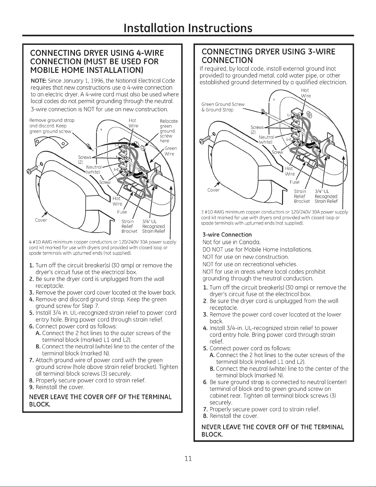
CONNECTING DRYER USING 4-WIRE
CONNECTION (MUST BE USED FOR
MOBILE HOME INSTALLATION)
NOTE:Since January !, !996, the National Electrical Code
requires that new constructions use a q-wire connection
to an electric dryer. A q-wire cord must also be used where
local codes do not permit grounding through the neutral.
3-wire connection is NOTfor use on new construction.
Remove ground strap Hot Relocate
and discard, Keep Wire green
greengroundscrew
here
Fuse
Cover
4 #10 AWG minimum copper conductors or 120/240V 50A power supply
cord kit marked for use with dryers and provided with closed loop or
spade terminals with upturned ends (not supplied).
1. Turn off the circuit breaker(s) (:SOamp) or remove the
dryer's circuit fuse at the electrical box.
2. Be sure the dryer cord is unplugged from the wall
receptacle.
3. Removethe power cord cover located at the lower back.
4. Remove and discard ground strap. Keep the green
ground screw for Step 7.
5. Install 3/4 in. UL-recognized strain relief to power cord
entry hole. Bring power cord through strain relief.
6. Connect power cord as follows:
A. Connect the 2 hot lines to the outer screws of the
terminal block (marked L1and L2).
B.Connect the neutral (white) line to the center of the
terminal block (marked N).
7. Attach ground wire of power cord with the green
ground screw (hole above strain relief bracket). Tighten
all terminal block screws (3)securely.
8. Properly secure power cord to strain relief.
9. Reinstall the cover.
NEVER LEAVE THE COVER OFF OF THE TERMINAL
BLOCK.
Strain 3/4" UL
Relief Recognized
Bracket Strain Relief
CONNECTING DRYER USING 3-WIRE
CONNECTION
If required, by local code, install external ground (not
provided) to grounded metal, cold water pipe, or other
established ground determined by a qualified electrician.
Hot
Wire
Green Ground Screw
& Ground Strap
]
Fuse
Cover
] #10 AWG minimum copper conductors or 120/240V ]OA power supply
cord kit marked for use with dryers and provided with closed loop or
spade terminals with upturned ends (not supplied).
3-wire Connection
Not for use in Canada.
DONOT use for Mobile Home Installations.
NOTfor use on new construction.
NOTfor use on recreational vehicles.
NOTfor use in areas where local codes prohibit
grounding through the neutral conduction.
1. Turn off the circuit breaker(s) (30 amp) or remove the
dryer's circuit fuse at the electrical box.
2. Besure the dryer cord is unplugged from the wall
receptacle.
3. Remove the power cord cover located at the lower
back.
4. Install 3/a-in. UL-recognized strain relief to power
cord entry hole. Bring power cord through strain
relief.
5. Connect power cord as follows:
A. Connect the 2 hot lines to the outer screws of the
terminal block (marked L1and L2).
B.Connect the neutral (white) line to the center of the
terminal block (marked N).
6. Besure ground strap is connected to neutral (center)
terminal of block and to green ground screw on
cabinet rear. Tighten all terminal block screws (3)
securely.
7. Properly secure power cord to strain relief.
8. Reinstall the cover.
Strain 3/4" UL
Relief Recognized
Bracket StrainRelief
NEVER LEAVE THE COVER OFF OF THE TERMINAL
BLOCK.
11
Page 12
Installation Instructions
EXHAUSTING THE DRYER
- Fire Hazard
This dryer MUST be vented to the outdoors.
Use only 4" rigid metal ducting for the home
exhaust vent.
Use only 4" rigid metal or UL-LISTEDtransition duct
to connect the dryer to the home exhaust duct.
DO NOT use a plastic vent.
DO NOT exhaust into a chimney, kitchen exhaust,
gas vent, wall, ceiling, attic, crawl space, or
concealed space of a building.
DO NOT install a screen in or over the exhaust duct.
DO NOT use duct longer than specified in the
exhaust length table.
Failure to follow these instructions can result in
death or fire.
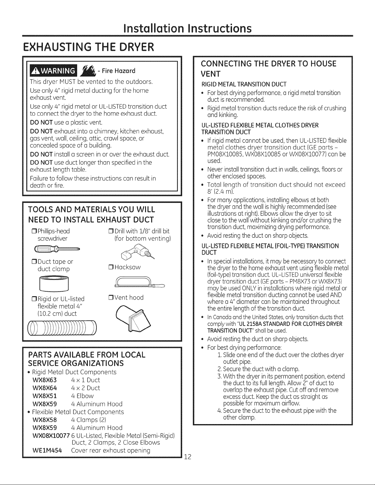
TOOLS AND MATERIALS YOU WILL
NEED TO INSTALL EXHAUST DUCT
C1Phillips-head
screwdriver
17Duct tape or
duct clamp
17Rigid or UL-listed
flexible metal 4"
(10.2 cm) duct
17Drill with 1/8" drill bit
(for bottom venting)
C1Hacksaw
17Vent hood
%
PARTS AVAILABLE FROM LOCAL
SERVICE ORGANIZATIONS
• Rigid Metal Duct Components
WXSX63 4 x 1 Duct
WX8X64 4 x 2 Duct
WX8XS1 4 Elbow
WX8×S9 4 Aluminum Hood
Flexible Metal Duct Components
W×8XS8 4 Clamps (2)
WX8×59 4 Aluminum Hood
WX08×::[0077 6 UL-Listed, Flexible Metal (Semi-Rigid)
Duct, 2 Clamps, 2 Close Elbows
WE1H454 Cover rear exhaust opening
CONNECTING THE DRYER TO HOUSE
VENT
RIGID METALTRANSITIONDUCT
Forbest drying performance, a rigid metal transition
duct isrecommended.
Rigidmetal transition ducts reduce the risk of crushing
and kinking.
UL-LISTEDFLEXIBLEMETAL CLOTHESDRYER
TRANSITIONDUCT
If rigid metal cannot be used, then UL-LISTEDflexible
metal clothes dryer transition duct (GEparts -
PIO8XlO085, WXO8XlO085 or WXO8XlO077) can be
used.
• Never install transition duct in walls, ceilings,floors or
other enclosed spaces.
Total length of transition duct should not exceed
8' (2.4 m).
Formany applications, installing elbows at both
the dryer and the wall is highly recommended (see
illustrations at right). Elbows allow the dryer to sit
close to the wall without kinking and/or crushing the
transition duct, maximizing drying performance.
Avoid resting the duct on sharp objects.
UL-LISTEDFLEXIBLEMETAL (FOIL-TYPE)TRANSITION
DUCT
• Inspecial installations, it may be necessary to connect
the dryer to the home exhaust vent using flexible metal
(foil-type) transition duct. UL-LISTEDuniversal flexible
dryer transition duct (GEparts - PM8X73or WX8X73)
may be used ONLYin installations where rigid metal or
flexible metal transition ducting cannot be used AND
where a 4" diameter can be maintained throughout
the entire length of the transition duct.
InCanadaandthe UnitedStates,onlytransition ductsthat
comply with "UL2158ASTANDARDFORCLOTHESDRYER
TRANSITIONDUCT"shall be used.
®
Avoid resting the duct on sharp objects.
®
Forbest drying performance:
1.Slide one end of the duct over the clothes dryer
outlet pipe.
2.Secure the duct with aclamp.
]. With the dryer in its permanent position, extend
the duct to its full length. Allow 2" of duct to
overlap the exhaust pipe. Cut off and remove
excess duct. Keep the duct as straight as
possible for maximum airflow.
4.Secure the duct to the exhaust pipe with the
other clamp.
12
Page 13

Installation Instructions
• DO cut duct as short
as possible and install
straight into wall.
(
,,DO NOT use
or collapse
ducting. Use
elbows if turns
,DO NOT bend
ore necessary.
@
EXHAUST LENGTH
Using exhaust longer than specified length will:
• Increase the drying times and the energy cost.
• Reduce the dryer life.
• Accumulate lint, creating a potential fire
hazard.
The correct exhaust installation is YOUR
RESPONSIBILITY,
Problems due to incorrect installation are not
covered by the warranty.
The HAXIHUH ALLOWABLE length of the exhaust
system depends upon the type of duct, number of
turns, the type of exhaust hood (wall cap) and all
conditions noted on the chart.
, Internal elbows added for side or bottom vent
conversions must be included in the total elbow
count.
, Any elbow greater than 45° should be treated as
a 90 ° elbow.
, Two 45 ° elbows will be treated like one 90 ° elbow.
, For every additional 90 ° elbow, reduce the
allowable vent system length by 10 feet.
, When calculating the total vent system length,
you must add all the straight portions and
elbows of the system (including the transition
duct).
excessive
exhaust
length. Cut
duct us short
us possible.
No.of 90°
Elbows
0
1
2
3
4
5
DO use elbows when
turns are necessary.
Elbows
• DO NOT _,DO NOT
crush duct _}?"X," set dryer
against the sx rU I on duct.
wall. _'
EXHAUST LENGTH
RECOMMENDEDMAXIMUMLENGTH
Exhaust Hood Types
Recommended
Rigid
Metal
120 Feet
100 Feet
85 Feet
70 Feet
60 Feet
55 Feet
Use only for short
run installations
4" DIA.
___ 2-1/2"
Rigid
Metal
90 Feet
75 Feet
65 Feet
55 Feet
45 Feet
55 Feet
13
Page 14

Installation Instructions
EXHAUSTING THE DRYER{cont.}
EXHAUST SYSTEM CHECKLIST
HOOD ORWALL CAP
• Terminate ina manner to prevent back drafts or entry
of birds or other wildlife.
• Termination should present minimal resistance to
the exhaust airflow and should require little or no
maintenance to prevent clogging.
Wall caps must be installed at least 12" above ground
level or any other obstruction with the opening
pointed down.
SEPARATIONOFTURNS
• For best performance, separate all turns by at least
4 ft. of straight duct, including distance between last
turn and dampened wall cap.
SEALINGOFJOINTS
• Alljoints should be tight to avoid leaks.The male end
of each section of duct must point away from the
dryer.
• Duct joints should be made air- and moisture-tight
by wrapping the overlapped joints with duct tape or
aluminum tape.
Do not assemble ductwork with any fasteners
that extend into the duct. These fasteners can
accumulate lint, creating a potential fire hazard.
• Horizontal runs should slope down towards the
outdoors 1/4" per foot.
Provide an access for inspection and cleaning of
the exhaust system, especially at turns and joints.
Exhaust system shall be inspected and cleaned at
least once a year.
INSULATION
• Ductwork that runs through an unheated area or is
near air conditioning should be insulated to reduce
condensation and lint buildup.
BEFORE YOU BEGIN
STANDARD REAR EXHAUST
We recommend that you install your dryer before
installing your washer. This will permit direct
access for easier exhaust connection.
Slide the end of the exhaust duct on the back of the
dryer and secure with duct tape or a duct clamp.
EXTERNAL DUCT
OPENING
DUCT TAPE OR
DUCT CLAMP
4" METAL DUCT CUT
TO PROPER LENGTH
DUCT TAPE OR
DUCT CLAMP
NOTE: We strongly recommend using rigid metal
exhaust duct. However, if flexible ducting is used it
must be UL-Listed metal, not plastic.
• For straight-line installation, connect the dryer
exhaust to the wall, using duct tape or a duct
clamp.
RECOMMENDED CONFIGURATION TO
MINIMIZE EXHAUST BLOCKAGE
Using duct elbows will prevent duct kinking and
collapsing.
• Remove and discard existing plastic or metal foil
duct and replace with UL-listed duct.
Remove any lint from the wall exhaust opening.
Wall
Internal
Duct
Check that exhaust
hood damper opens
and closes freely.
Transition
Ducting
\
14
Page 15

Installation Instructions
SIDE OR BOTTOM VENTING
Dryer Exhaust to right of cabinet for Electric
models only.
Dryer Exhaust to left of cabinet for Gas and
Electric models.
Dryer Exhaust to the bottom of cabinet for
Gas and Electric models.
- Fire Hazard
Close the back opening with cover plate (Kit
WE1M454).
Disconnect dryer from electrical supply.
Wear gloves and arm guards.
Failure to do so may result in fire, electrical shock
or lacerations.
Right
(electric
models
only)
Remove
screw
and save
O" Left
Bottom
Remove desired
knockout (one only)
Detach and remove the right (electric models only),
left or bottom knockout as desired. Remove the
screw inside the dryer exhaust duct and save. Pull
the duct out of the dryer.
Fixing hole
\
', A
i
L.................... _
For models GTD60, GTD65 and GTD68 only, use the
dimension below.
i
I_ 9-1/2" (24.13cm)_I
Fixing hole
TAB LOCATION
gas
BENDTAB
UP45°
Through the rear opening, locate the tab in the
middle of the appliance base. Lift the tab to about
45°,using a flat-blade screwdriver.
ADDING A NEW DUCT
Fixing hole Portion "A)'
Right(electric _,,1[ > k]<"i ';" "_"y ,;,;-_/ i ,,/
modelsonly)or _ I:_ `)'y-
left side exhaust -.._._:_ _
Reconnect the cut portion (A)of the duct to the
blower housing. Make sure that the shortened
duct is aligned with the tab in the base. Use the
screw saved previously to secure the duct in place
through the tab on the appliance bose.
ADDING ELBOW AND DUCT FOR EXHAUST TO
SIDE OF CABINET
Rig.h ./ _
Exhaust can_ _;'Z _J'_
be added to _---__
right (electric _ _ _'r_,,_,
models only) "_ Left ....
= i,):
Left
or left side t__"__ tape
Cut the duct as shown and keep portion A.
• Preassemble 4" elbow with 4" duct. Wrap duct
tape around joint.
• Insert duct assembly, elbow first, through the
side opening and connect the elbow to the dryer
internal duct.
Be sure not to pull or damage the electrical wires
inside the dryer when inserting the duct,
15
Page 16

Installation Instructions
EXHAUSTINGTHE DRYER{cont.)
SIDE OR BOTTOM VENTING (cont.)
ADDING ELBOW AND DUCT FOR EXHAUST TO
LEFT OR RIGHT SIDE OF CABINET {cont.)
• Apply duct tape as
shown on thejoint
between the dryer
internal duct and the
elbow, and also the joint
between the elbow and
the side duct.
Use 4" rigid metal ducting only inside the dryer.
Internal duct joints must be secured with tape,
otherwise they may separate and cause a safety
hazard.
ADDING ELBOW FOR EXHAUST THROUGH
BOTTOM OF CABINET
Insert the elbow through the rear opening and
connect it to the dryer internal duct.
Apply duct tape as Duct tape
shown on the joint
between the dryer
internal duct and the
elbow, and also the
joint between the
elbow and the bottom
duct.
Internal duct joints must be secured with tape;
otherwise, they may separate and cause a safety
hazard.
DUCT
TAPE
FINAL SETUP
I]-I LEVEL THE DRYER
Stand the dryer upright near the final location and
adjust the leveling legs at the corners to ensure
the dryer is level side-to-side and front-to-back.
Then, adjust the two anti-tip legs at the front inner
corners, taking care that they are touching the
floor to avoid unit tip over. The installation is not
complete until this process is finished.
Raise Lower
Anti-Tip Legs
[-2] PLUG DRYER IN
Ensure proper
ground exists
before use.
ADDING COVER PLATE TO REAR OF CABINET
Plate
(Kit WE1M4S4)
Connect standard metal elbows and ducts to
complete the exhaust system. Cover back opening
with a plate (Kit WE1M4S4) available from your
local service provider. Place dryer in final location.
NEVER LEAVE THE BACK OPENING WITHOUT THE
PLATE. (Kit WEl1454.)
r_ DRYER START-UP
Press the Power button.
NOTE: If the dryer has been exposed to
temperatures below freezing for an extended
period of time, allow it to warm up before pressing
Power. Otherwise, the display will not come on.
The dryer is now ready for use.
16
Power
Page 17

Installation
REVERSINGTHE DOOR
Instructions
ABOUT REVERSING THE DOOR
IMPORTANT NOTES:
• Read the instructions oil the way through before
starting.
• Handle ports carefully to ovoid scratching point.
Set screws down by their related ports to ovoid
using them in the wrong places.
Provide a non-scratch work surface for the door.
Normal completion time to reverse the door
swing is 30-60 minutes.
IMPORTANT:
Once you begin,do not move the cabinetuntildoor
swing reversaliscompleted.These instructionsore
forchanging the hingesfrom therightsidetothe left
side-ifyou everwont toswitchthem beck tothe
rightside,followthesesome instructionsend reverse
allreferencestothe leftand right.
Tools needed:
[] Standard #2 Phillips screwdriver
[] Tape-tipped putty knife
[] Small flat blade screwdriver
Unplug the dryer from its
electrical outlet
[] REVERSING THE DOOR- SOLID DOOR
MODELS (cont.}
P]
Remove the bottom screw from each hinge (right
side) and partially insert them into each top hinge
hole on the left side.
NOTE:All 4 front panel hinge screws will now be in
the top hinge holes- 2on the left and 2 on the right.
FI Loosen each top hinge screw on right side. Remove
the door and place it on a protective flat surface to
avoid any damage.
Loosen each top
hinge screw on
right side
Choose the REVERSING THE DOOR instructions
rA-]or r_ for your model.
F_ REVERSING THE DOOR- SOLID DOOR
MODELS
r_ open the door 130 With
putty knife, remove the 4 plastic caps located along
the left side of the front panel and set them aside.
approximately degrees.
Plastic Cap (4)
Left side of
front panel
1 S
r4-]Remove both the blind plate and the strike plate and
install them in opposite positions.
a
17
Blind
p](
Strike
plate
Page 18

Installation Instructions
REVERSINGTHE DOOR(cont.}
r_ REVERSING THE DOOR-SOLID DOOR
MODELS (cont.)
r_ Mount the door on the 2 upper left side hinge screws
installed in step 2. Move the hinge screws loosened in
step 3 into the lower left side screw holes and firmly
tighten all 4 screws.
Hang door and
tighten screws
Door
\
\
\ ,,
-6-]Install the 4 plastic caps removed in step 1 into the 4
right side front panel holes.
Plastic Cap (4)
Right side of _:_-_
front panel
NOTE:To return the door to the original setup, follow
these instructions, swapping "left" and "right".
When you finish
Plugthe dryer back into
its electrical outlet.
18
Page 19

Installation
REVERSINGTHE DOOR
Instructions
r_ REVERSING THE DOOR - GLASS PANEL
DOOR MODELS
FJopen the door 130 Withapproximately degrees.
putty knife, remove the 4 plastic caps located along
the left side of the front panel and set them aside.
Plastic Cap (4)
%
front panel
f Left side of
F] Remove the bottom screw from each hinge (right
side)and partially insert them into each top hinge
hole on the left side.
NOTE:All/4 front panel hinge screws will now be in
the top hinge holes- 2 on the left and 2 on the right.
FB1REVERSING THE DOOR - GLASS PANEL
DOOR MODELS (cont.}
a
r4--]Remove both the blind plate and the strike plate and
install them in the opposite positions.
Blind
Strike
plate
FJ Remove the 4 door hinge screws, 6 inside screws and
2 pocket screws. Lift the inner door upwards using a
flat blade screwdriver.
Pocket screws
Inside
screws
-31Loosen each top hinge screw on right side. Remove
the door and place it on a protective flat surface to
avoid any damage.
Loosen each top
hinge screw on
right side
/ S
19
Door
hinge
screws
I
Inside
screws
Page 20

Installation Instructions
REVERSINGTHE DOOR(cont.}
[] REVERSING THE DOOR - GLASS PANEL
DOOR MODELS (cont.)
F6-]Remove and swap the 2 plastic caps and the 2
hinges.
Install plastic caps
from oposite side
/_ Plastic
/ I caps
here Install hinges from
oposite side
here
P] Rotate the outer door 180 degrees, mount the inner
door back into the outer door frame and secure with
the screws removed in step 5. Make sure you mount
the hinges on the side opposite the pocket.
Inside
screws
Pocket screws
___" rews
Door
hinge
REVERSING THE DOOR - GLASS PANEL
DOOR MODELS (cont.)
F8-]Mount the assembled door on the 2 upper left side
hinge screws installed in step 2. Move the hinge
screws loosened in step 2 into the lower left side
screw holes and firmly tighten all 4 screws.
Hang door and
tighten screws
Door
\
\ ,,
rg] install the 4 plastic caps removed in step 1into the 4
right side front panel holes.
Plastic Cap (4)
Ins
Inside
screw
Inside
screw
Right side of >-_--_
front panel
NOTE:To return the door to the original setup, follow
these instructions, swapping "left" and "right".
When you finish
plugthe dryer back into
its electrical outlet.
20
Page 21

Instrucciones
J
S d
in tol " n
i Si tiene alguna pregunta, flame a 800.GE.CARES (800.432.2737) o visite nuestro sitio Web en: GEAppliances.com i
_ Esteesels[mbolodealerta de seguridad.Elmismoalertasabrepotencialesriesgosque lepuedenproducirla muerte
o lesionestanto a ustedcoma a otras personas.Todoslosmensajesdeseguridadestar6na continuaci6ndelsimbolo
dealertadeseguridady con la palabra"PELIGRO","ADVERTENCIA"o "PRECAUCION".Estaspalabrassedefinencoma:
Indica una situaci6n de riesgo que,si no se evita, producir6 la muerte o lesionesgraves.
Indica una situaci6n de riesgo que,si no se evita, podria producir la muerte o lesiones graves.
_ Indica una situaci6n de riesgo qua,si no se evita, podria resultar en lesionesmenores o moderadas.
ANTES DE COMENZAR
Lea estas instrucciones par completo y con
detenimiento.
. IMPORTANTE-Guardeestasinstrucciones
para el usa de inspectores el@ctricos locales.
, IMPORTANTE-Cumplacon todos los
c6digos y ordenanzas vigentes.
, Instale la secadora de acuerdo con las instrucciones
del fabricante y los c6digos locales.
, Nota al instalador- Aseg_rese de dejar estas
instrucciones con el consumidor.
Noto al usuario - Conserveestas instrucciones para
referencia futura.
Lainstalaci6n de la secadoradebeefectuarla un
instalador calificado.
o
Esta secadora debe tenet una salida al exterior.
o
Antesde que la secadora antigua searetirada del
servicioo eliminada,qdtele la puerta.
Lainformaci6n sabre reparaciones y el diagrama del
cableacloseencuentran enla consola decontrol.
, No permita que niBossesuban o se metan dentro
del artefacto. Serequiereuna supervisi6nestricta
cuando el aparato es utilizado cerca de ninos.
, Elinstalador tiene la responsabilidadde efectuar una
instalaci6n adecuada.
Lagarant[a no cubrelas fallas del producto debido a
una instalaci6n incorrecta..
Instale la secadoraen lugaresdonde latemperatura
seamayor a 50°Fpara un funcionamiento
satisfactorio del sistema de control de la secadora.
Quite y descarte el conducto existente de pldstico
o de papel de aluminio y coloque un conducto
aprobado por UL.
__- Riesgo de incendio
• La instalaci6n de la secactora ctebeefectuarla un
instalador calificado.
Instalela secadora de ropa de acuerdo con estas
instruccionesyen cumplimiento con los c6digos
locales
• NO instale una secadora de ropa con conductos
de pl6stico flexible. Si se instala un conducto
flexible de metal (semi rigido o de tipo papel de
aluminio), debe estar aprobado por UL e instalarse
de acuerdo con las instrucciones de "C6mo
conectar la secadora a la ventilaci6n dom6stica"
de este manual. Los materiales de los conductos
flexibles a menudo se desploman, se aplastan y
atrapan pelusas. Estas condiciones obstruyen la
corriente de aire de la secadora e incrementan el
riesgo de incendio.
• NO instale o almacene este aparato en un
lugar donde se vea expuesto al agua o alas
inclemencias del tiempo.
Para reducir el riesgo de una lesi6n grave o de
muerte, cumpla con todas las instrucciones de
instalaci6n.
Guarde estas instrucciones. (Instaladores:
Aseg0rense de dejar estas instrucciones al
consumidor).
Impreso en M6×ico
234D2318P001
31-16767-Io5-15GE
Page 22

Instruccionesde instalaci6n
Advertencias de la Proposici6n 65 del Estado de California:
La Leysabre Agua Potable Inocua y Tratamiento de ResiduosT6xicos de California (California Safe Drinking Water and
Toxic Enforcement Act)solicita al Gobernador de California que publique una lista de sustancias que el estado reconoce
que producen c6ncer, defectos de nacimiento uotros daflos reproductivos y solicita alas empresas que adviertan sabre la
posible exposici6n a tales sustancias.
Este producto contiene uno o m6s qu[micos que el Estado de California entiende que producen c6ncer,
defectos en el nacimiento u otros dahos reproductivos.
Los electrodom#sticos a gas puedan causar una exposici6n de bajo nivel a algunas de estas sustancias, incluyendo
benceno, mon6xido de carbono, formaldehido y hall[n,ocasionado principalmente par lacombusti6n incompleta de
gas natural o combustibles de LRLa exposici6n a estas sustancias puede set minimizada ventilando correctamente la
secadora hacia el exterior.
C6MO DESEMPACAR LA SECADORA
Incline la secadora de costado y saque los patios de
espuma de embalaje tirando de los costados y quit6ndolos
de las patas de la secadora. AsegOrese de quitar todas las
piezas de espuma de las patas.
Saque la literatura y la balsa que contiene la informaci6n.
DIMENSIONES
APROXIMADAS
Pie
C6bico × Y
43 3/8" 26 3/4"
6.0 (110 cm) (68 cm)
43 3/8" 29 1/2"
7.0 (110 cm) (75 cm)
43 314" 30 1/2"
7.3 (iiicm) (78cm)
27"
(68,8 cm)
Visi6n frontal
MANGUERA DE VAPOR V AGUA:
GE recomienda enfdticamente el usa de piezas especfficas
de f6brica. A continuaci6n figura una lista de mangueras
de fabricas que podr6 adquirir. Dichas mangueras son
fabricadas y probadas de modo que se cubran las
especificaciones de GE.
GErecomienda enf6ticamente el usade nuevas mangueras
de suministro de agua. Con el paso del tiempo, las mangueras
sedegradas y deben ser reemplazadas cada 5 aflos, a fin de
reducir el riesgode fallas sobre lasmismas y dahos con el agua.
Piezasy Accesorios
Ordenehay a trav@sde Interneten GEApplioncesports.com,
las 24 horas del d[a o en forma telef6nica Ilamando al
800.626.2002, durante el horario comercial habitual.
X
N6mero de Pieza
WE25X20060
0
WEl[v1847
WEOIX22395
P[v114XlO056
WXI4XIO007
X
b_-4 5/8"
Visi6n lateral
1,7 cm)
4 1/4"
(10,8 cm)
Accesorio
Kitcompleto(mangueras,lavadoracon
adaptadorenY)(incluido)
Mangueralargay
Mangueracorta
Cepillodeventilaci6ndelaaberturadela
puertadela secadora(noincluido)
CepillocontuberiagiratoriaLintEaterTM (no
incluido)
Page 23

Instruccionesde instalaci6n
REQUERIMIENTOS PARA INSTALACION
EN NICHOS 0 ARMARIOS
_ _'- Riesgo de explosi6n
lViantengacualquiermaterial y vaporesinflamables,
talescoma gasolina,alejadosdela secadora.
Coloque la secadora a por Iomenos 18" (46cm.)del
piso cuando sea instalada en un garaje.
si nosecumplecon esto,se podr6 produciruna
explosi6n,incendioo la muerte.
Si se aprob6 la instalaci6n de su secadora en
alcoba o armario, esto figurar6 en una etiqueta
en el reverso de la secadora.
• Esta secadora DEBEtener una ventilaci6n
al exterior. Ver la secci6n SALIDA AL EXTERIOR
DE LA SECADORA.
• El espacio libre minimo entre la secadora y las
paredes adyacentes u otras superficies es:
0" en ambos lados
3" (7.62 cm) en el frente
0" en la parte trasera pero 1" (2.54 cm)
minimo es la recomendada
• El espacio vertical minimo de la parte superior de la
secadora basra losestantes,armarios, techos, etc,es de 1.
• Se deber6 considerar que se debe brindar el despeje
adecuado para la instalaci6n y el servicio t6cnico.
• Las puertas del armario deben contar con rejillas
u otro tipo de ventilaci6n y tenet por Io menos
60 pulgadas cuadradas de espacio abierto
igualmente distribuido. Si el armario incluye una
lavadora y una secadora, las puertas deben
contener un minimo de 120 pulgadas cuadradas
de espacio abierto distribuido uniformemente.
NOTA: CUANDO ELCONDUCTO DE ESCAPE SE
ENCUENTRAENLA PARTETRASERADE LA SECADORA,
LA CONFIGURACION DEL DUCTO DE ESCAPEPUEDE
REQUERIR MAS DE 0" DE ESPACIO EN LA PARTE
TRASERA.1" (2.54 CH) HiNIHO ESLA RECOHENDADA.
Secadoras a Gas 0nicamente:
• No se deber6 instalar ningOn otro electrodom6stico
que consuma combustible en el mismo armario
donde haya una secadora a gas.
• La secadora se deber6 desconectar de la tuberia
de suministro de gas durante la prueba de presi6n
en presiones superiores a !4 psi (3.5 kPa).
Secadoras a Gas Unicamente - continuado:
• Una rosca cubierta NPT de 1/8", accesible para
la conexi6n de un dispositivo de calibraci6n,
deber6 ser instalada inmediatamente arriba de la
conexi6n del suministro de gas a la secadora.
ESPACIO LIBRE MJNIMO EN OTROS
ESPACIOS QUE NO SEAN INSTALACIONES
EN NICHOS 0 ARMARIOS
Los espacios libres minimos respecto de superficies
combustibles y de aberturas de aire son: O"a ambos
lados; 1" (2.54 cm) en el frente; O" en la parte trasera
pero 1" (2.54 cm) minimo es la recomendada. Debe
tenerse en cuenta un espacio libre adecuado para
un funcionamiento y reparaci6n correctos.
INSTALACI6N EN CASAS M6VILES
0 PREFABRICADAS
• Instalaci6n debe cumplir con la NORtVlA
SOBRE CONSTRUCCION Y SEGURIDAD DECASAS
PREFABRICADAS,TiTULO 24, PARTE 32-80 o
Norma CAN/CSA-Z240 iVlH, o, cuando dicha
norma no sea aplicable, con la NORMA NACIONAL
ESTADOUNIDENSE PARA CASAS Ivl0VILES, ANSI/
NFPA N° 501B.
• La secadora DEBE tener ventilaci6n al exterior. La
ventilaci6n del escape deber6 estar ajustado de
forma segura a una parte no combustible de la
casa rodante.
La ventilaci6n NO DEBEterminar debajo de una
casa m6vil o prefabricada.
Elmaterial del conducto de ventilaci6n DEBESERMETAL.
DEBE utilizarse el KIT 14-D346-33 para conectar
bien la secadora a la estructura.
La ventilaci6n NO DEBE conectarse a ningOn otro
conducto, ventilaci6n o chimenea.
No utilice tornillos para placas de metal u otros
dispositivos de sujeci6n que se extiendan
al interior de la ventilaci6n de salida.
Debe contar con una abertura con un espacio libre de
pot Io menos 25 pulgadas cuadradas para el ingreso
de aire exterior dentro de la secadora habitaci6n.
Para acceder a informaci6n sobre la conexi6n
el6ctrica, consulte la section.
CABLES DE CORRIENTE:
GErecomienda enf@icamente el usode piezasespec[ficasde
fabrica. Seleccioneel cable de corriente que seadecQea sus
requisitos de instalaci6n.
Ordene a trav6s de Internet en GEAppliancesParts.com, las 2z_
horas del d[ao en forma telef6nica Ilamando a1800.626.2002,
durante elhorario comercial habitual.
Pieza N° Tipo Longitud Amperios
wxgx2 3-ClavUas 4 Pies 30
wxgx3 ]-Clavijas SPies 30
wxgx4 3-Clavijas 6 pies 30
wxgx!8 4-Clavijas 4 pies 30
wxgx!9 4-Clavijas SPies 30
WX9X20 4-Clavijas 6 Pies 30
]
Page 24

Instruccionesde instolaci6n
C6MO CONECTAR MANGUERAS DE ENTRADA
C6MO CONECTAR MANGUERAS
DE ENTRADA
Para producir vapor, la secadora debe conectarse
al suministro de agua fria. Ya que la lavadora
tambi6n debe conectarse al agua fria, debe
introducirse un conector en "Y" para permitir que
ambas mangueras de entrada puedan utilizarse al
mismo tiempo.
NOTA: Utilice las nuevas mangueras de entrada
provistas; nunca utilice mangueras viejas.
.
Cierre el grifo de agua frTa. Quite la manguera
de entrada de la lavadora del conector de la
v61vula de Ilenado (fria).
2. AsegOrese de que la arandela plana de goma
se encuentre en su lugar y sujete una uni6n
hembra de la manguera corta en el conector
de la v61vulade Ilenado de la lavadora. Ajuste a
mano hasta que est6 firmemente asentada.
3. sujete un extremo macho del conector en
"V" a la uni6n hembra de la manguera corta.
Aseg0rese de que la arandela plana de goma se
encuentre en su lugar. Ajuste a mano hasta que
est6 firmemente asentada.
C6MO CONECTAR MANGUERAS
DE ENTRADA (cont.)
7. Utilizando alicates, ajuste todas las uniones con
un giro adicional de dos tercios.
NOTA: No ajuste de m6s. Pueden da_arse las
uniones.
,
Introduzca el filtro en la uni6n de la manguera
de entrada de la lavadora. Si la arandela plana
de goma ya se encuentra en su lugar, quitela
antes de instalar el filtro, sujete esta uni6n a
un extremo macho del conector en "V". Ajuste
a mano hasta que est6 firmemente asentada.
,
AsegOrese de que la arandela plana de goma
se encuentre en su lugar y sujete la manguera
larga de entrada de la secadora a un extremo
macho del conector en "V".Ajuste a mano hasta
que est6 firmemente asentada.
,
Aseg0rese de que la arandela plana de goma se
encuentre en su lugar y sujete el otro extremo
de la manguera larga de entrada al conector
de la v61vula de Ilenado en la parte inferior del
panel trasero de la secadora. Ajuste a mano
hasta que est6 firmemente asentada.
8. Abra el grifo de agua.
9. Controle la presencia de p6rdidas alrededor
del conector en "V",el grifo y las uniones
de las mangueras.
REOUISITOS DE SUMINISTRO DE AGUA
Los grifos de agua caliente y fria DEBEN instalarse
dentro de las 42 pulg.(107 cm) de la entrada de
agua de la lavadora. Los grifos DEBEN set del tipo
de manguera dejardin de 3/4 pulg. (1.9 cm) para
que las mangueras de entrada puedan conectarse.
La presi6n de agua DEBE hallarse entre 10 y 120
libras por pulgada cuadrada. La compa_ia de agua
puede informarle sobre la presi6n de agua.
NOTA: Se recomienda el uso de un suavizante de
agua para reducir la acumulaci6n de sarro dentro
del generador de vapor si el suministro dom6stico
contiene agua muy dura.
4
Page 25

Instruccionesde instoloci6n
COHO CONECTAR UNA SECADORA A GAS
(sise cuento con uno secodoro el_ctrico0solteoresteposol
HERRAMIENTAS NECESARIAS
O Llaves ajustables OOestornillador
de 10" (2) de lados pianos
OLlave para tubos de
OPinzas
ONivel
MATERIALES NECESARIOS
OCodo de metal de
4" di6metro
O Compuesto o PTFE
cinta para tuberias
OConducto de metal
flexible de 4"
di6metro (si fuese
necesario)
OGuantes
Antes de comenzar la instalaci6n, apague
el disyuntor o quite los fusibles de la secadora
de la caja el6ctrica. Verifique que el cable
de la secadora est6 desenchufado
del tomacorriente.
Girea la posici6n OFF(apagado)la v61vulade gas
de la secadora de la linea de suministro.
V61vula
de cierre
O Conector de tuberia
de gas flexible
O Abrazaderas de tuberia
(2) o abrazaderas de
resorte (2)
%
OGafas de seguridad
O Conducto de metal de 4"
di6metro (recomendado)
)
04" Placa de cubierta
(Kit WE1M454)
OSoluci6n jabonosa
para detecci6n de
p@didas
OCampana de salida
OCinta aislante
OGas adaptador (2),
codo, y tap6n de
tuberfa
Desconecte y elimine el conector flexible de gas
y el material del conducto.
Page 26

Instruccionesde instalaci6n
COMO CONECTAR UNA SECADORA A GAS (cont.)
(sise cuenta con una secadora el ctrica, saltear este
REQUERIMIENTOS DE GAS
__!- Riesgo de e×plosi6n
• Useuna linea nueva de suministro de gas flexible
que est6 aprobada pot CSAInternational. Nunca
vuelva a usar conectores flexibles viejos.
• Instale la v61vulade cierre.
• Defarina segura ajuste todas las conexiones de
gas.
• Si la conexi6n fue realizada a gas LP, solicite a
una persona calificada que le asegure que la
presi6n del gas no supera una columna de agua
de 13".
Ejemplosde una persona calificada incluyen:
Personalde calefacci6n calificado, personal
autorizado de una compa_ia de gas,y personal
autorizado del servicio t6cnico.
• Si no se cumple con esto, se podr6 producir la
muerte, una explosi6n o incendio.
Esta secadora a gas est6 equipada con un
montaje de v61vula y quemador para utilizar s61o
con gas natural. Mediante el kit de conversi6n
WE25X217, la organizaci6n de atenci6n local
puede convertir esta secadora para su uso con
gas propano (LP).(Para convertir de gas propano
(LP)al gas natural, se utilizar6 el kit de conversi6n
WE25X218.) TODAS LASCONVERSIONES DEBEN
LLEVARLASA CABO PERSONAL CAPACITADO%'
CALIFICADO EN CUMPLIMIENTO CON CODIGOS
LOCALES%'REQUERIHIENTOSDE ORDENANZAS.
CONE×I6N DE SUMINISTRO DE GAS
DE LA SECADORA
SUMINISTRO DE GAS
• Debe instalarse una toma a rosca de 1/8" NPT,
accesible para una conexi6n del man6metro de
prueba, inmediatamente en sentido ascendente
de la conexi6n de suministro de gas hacia
la secadora. Sitiene dudas sobre la instalaci6n
de la toma, comuniquese con su empresa
proveedora de gas local.
• La linea de suministro debe set de tuberia rigida
de 1/2" y debe contar con un cierre accesible
dentro de los 6 piesde la secadora, dentro de la
misma habitaci6n donde se encuentra la misma.
Utilice compuesto para rosca de tuberia apropiado
para gas natural o LP o utilice cinta de PTFE.
Una el conector de metal flexible a la secadora
y al suministro de gas.
La instalaci6n deber6 ser conforme con los c6digos
locales, o en ausencia de los c6digos locales, con
el C6digo Nacional de Gas Combustible (National
Fuel Gas Code), ANSIZ223.1/NFPA 54, o el C6digo de
Instalaci6n de Gas Natural o Propano (Natural Gas
and Propane Installation Code), CSAB149.1.
EN LA MANCOMUNIDAD DE
MASSACH USETTS
• Este producto debe instalarlo un plomero
matriculado o un instalador de gas.
Cuando use v61vulas esf@icas de apagado
de gas, deber6n ser del tipo de manija en T.
Si se usa una conexi6n flexible para gas, 6sta
no debe superar los 3 pies.
AJUSTE PARA ELEVACI6N
1-7/8"
l "' SUMINISTRO DE GAS ROSCA MACHO NPT DE 3/8"
NOTA:Agreguea ia dimensi6nvertical iadistancia
entre la parte inferiordel gabinete y elpiso.
• Debe utilizar un conector flexible met61ico
listado por ANSI Z21.24/CSA 6.10. La Iongitud del
conector no exceder6 3 pies.
• Los niveles de entrada de las secadoras de ropa
a gas est6n basados en el funcionamiento al nivel
de mar y no necesitan ajustes para funcionar
en o pot debajo de los 2000 pies de elevaci6n.
Para un funcionamiento a m6s de 2000 pies de
elevaci6n, los niveles de entrada se deberian
reducir a un promedio del 4 por ciento pot cada
1000 pies sobre el nivel del mar.
• La instalaci6n debe cumplir con los c6digos
y ordenanzas locales, o en su ausencia, con
el CODIGO NACIONAL DE GAS COMBUSTIBLE
(NATIONAL FUEL GAS CODE),ANSI Z223.
6
Page 27

Instruccionesde instalaci6n
C6HO CONECTAR LA SECADORA
AL SUMINISTRO DE GAS
Instale un codo hembra NPT de 3/8" al final
@
de la entrada de gas de la secadora.
Instale un adaptador de uni6n c6nica
de 3/8" al codo hembra.
IIPORTANTE: Utilice una Ilave para tubas para
sostener bien el extremo de la entrada de gas
de la secadora para no doblar la entrada.
NOTA: Aplique compuesto para tuberia o cinta
PTFEa las roscas del adaptador y la entrada de
gas de la secadora.
Conector_
nuevo de I_ _
linea de gas _. I_\
de metal _¢_ "_b_._ /F\
flexible "_Z _\\
ndaptador "I_ _4s_d_i
odo/
NPTde 3/8"
Los productos que no suministrados
r_ una el conector de tuberia de gas de metal
flexible al adaptador.
/Adaptador
Tap6n de tuberia
_ paracontrolar
_. la presi6n de
_ entrada de gas
:_ V61vulade cierre
k_4r _ --
_-----Ta maffo de
npt de 1/8"
tuberia al
menos 1/2"
c6Ho CONECTAR LA SECADORA
AL SUHINISTRO DE GAS (cont.)
Instale una toma a rosca de 1/8" NPT
@
en la v61vulade apagado de latubefia de gas
de la secadora para controlar la presi6n
de gas en la entrada.
Instale un adaptador de uni6n c6nica
en la toma a rosca.
NOTA: Aplique compuesto para tuberia o cinta
PTFE alas roscas del adaptador y a la toma.
Aplique compuesto para
tuber[a o cinta PTFEen
todas las roscas macho.
V61vula de apagado .mmm_(
rE] Ajuste todas las conexiones mediante
dos Ilaves ajustables. No ajuste de m6s.
Tomaa
Aplique compuesto para tubena al
adaptador y a la entrada de gas de la
secadora.
r_ Ajuste la conexi6n de tuberia flexible de gas,
utilizando dos Ilaves ajustables.
rFj Cierre la v61vula de apagado del gas.
Page 28

Instruccionesde instalaci6n
COMO CONECTAR UNA SECADORA A GAS (cont.)
(sise cuenta con una secadora el ctrica, saltear este paso)
PRUEBA DE PI_RDIDAS
Nunca utilice una llama abierta para detectar
p_rdidas de gas.
Controle todas las conexiones con una soluci6n
jabonosa o un elemento equivalente.
Aplique una soluci6n jabonosa. Lasoluci6n para
controlar p@didas no debe contener amoniaco,
ya que este producto puede da_ar los accesorios
de bronce.
Sise detectan p@didas, cierre la v61vula,vuelva
a ajustar lajunta y repita la prueba de la soluci6n
jabonosa and repeat the soap test.
Abra la
v61vula
de ga_,._
CONE×I6N ELI_CTRICA INFORMACI6N
SOBRE LAS SECADORAS A GAS (cont.)
La secadora debe contar con una conexi6n
el6ctrica a tierra en cumplimiento con los c6digos
locales, o si 6stos no existieran, de acuerdo con
el C6digo EI6ctrico Nacional, ANSI/NFPA 70 o el
C6digo EI6ctrico Canadiense CSA C22.1.
Este artefacto debe contar con un suministro de
120V, 60Hz, debe estar conectado a un circuito
derivado individual con una adecuada conexi6n
a tierra y deben contar con la protecci6n de un
disyuntor o fusible de tiempo retardado de 15 o
20 amperios. Si el suministro el6ctrico provisto no
reOne estos requerimientos, es responsabilidad
del dueBo solicitar a un electricista calificado la
instalaci6n de un tomacorriente de 3 paras con
conexi6n a tierra.
CONE×I6N ELECTRICA INFORMACI6N
SOBRE LAS SECADORAS A GAS
_:_, - Riesgo de Descarga El_ctrica
Enchufe en un tomacorriente con conexi6n a tierra
de 3 cables.
NO retire la conexi6n a tierra.
NO UTILICE un cable de extensi6n.
NO UTILICE un enchufe adaptador con este
artefacto.
Si no se siguen estas instrucciones, se podr6
producir la muerte o descargas el6ctricas.
Verifique que haya
una conexi6n a tierra
adecuada antes del uso.
Silos c6digos locales Io permiten, se podr6 agregar
un cable a tierra externo (noprovisto), ajustando el
mismo al tomillo conectado a tierra de color verde
en la parte trasera de la secadora, y a una conexi6n
ca_eria met61ica de agua fria conectada a tierra u
otra conexi6n a tierra establecida.
Tornillo de
conexi6n
a tierra
8
Page 29

Instruccionesde instalaci6n
COHO CONECTAR UNA SECADORA ELECTRICA
(S61tesesise trata de las secadoras a gas o sisu secadora ya tiene un cable de alimentaci6n conectado)
HERRAMIENTAS NECESARIAS
O Pinzas
O Destornillador de
lados pianos O Nivel
O Destornillador Phillips
MATERIALES NECESARIOS
%
OCodo de metal de
4" de di6metro 17Guantes
OAlivio de tensi6n de
3/4" (reconocido par
UL)
OCampana de salida
Antes de efectuar la conexi6n el6ctrica, desactive
los disyuntores o quite los fusibles del circuito
de la secadora de la caja el6ctrica. Verifique
que el cable de la secadora est6 desenchufado
del tomacorriente. NUNCA OLVIDE DE VOLVER
A COLOCAR LA TAPA DE ACCESO DEL BLOq)UE
TERMINAL
%
OAbrazaderas de
tuberia de 4" (2)
o abrazaderas de
resorte de 4" (2)
OGafas de seguridad
17Conducto de metal
de 4" de di6metro
(recomendado)
17Conducto de metal
flexible de 4"
de di6metro
(si fuese necesario)
OCinta aislante
17Kit de cable de
energia de la
secadora (no incluido
con la secadora)
Clasificado UL, de
120/240V, 30A con
3 o 4 patas. Identifique
el tipo de enchufe
segOn el tomacorriente
de la vivienda antes de
comprar el cable.
¢]
O4" Placa de cubierta
(Kit WE1M4S4)
Page 30

Instruccionesde instalaci6n
COMO CONECTAR UNA SECADORA ELECTRICA (cont.)
S61tese sise trata de lassecadoras a gas o sisu secadora ya tiene un cable de alimentaci6n conectado
CONE×I6N ELI_CTRICA INFORMACI6N
SABRE LAS SECADORAS ELI_CTRICAS
Para realizar conexiones el_ctricas con
un cable de corriente:
_f_- Riesgo de incendio
Use un cable de suministro de carriente de la secadara
de 30 amperes y 240V de la lista de UL,can terminales
de anilla cerradas a terminales de espada can
extremas al rev6s.
Use un amartiguadar can refuerza de la lista de UL
Descanecte la carriente antes de realizar canexianes
el6ctricas.
Canecte elcable neutra (el blanca a el cable central)a
la terminal central.
Elcable a tierra (verde o pelado) se deber6 conectar al
canectar a tierra verde.
Canecte las das cables de suministra restantes alas
das terminales restantes.
De farma segura ajuste tadas las canexianes el6ctricas.
Reemplace latapa del blaque terminal.
Si no cumple con esto, se podr6 producir la muerte,
incendia a descarga el6ctrica.
INSTRUCClONES DE CONE×I6N A TIERRA
Para una secadora conectada con cable con
cone×i6n a tierra: Esta secadora deber6 estar
conectado a tierra. En caso de mal funcionamiento
o averia, la conexi6n a tierra reducir6 el riesgo
de descargas ei6ctricas al brindar un camino con
una resistencia menor para ia corriente ei6ctrica.
Esta secadora est6 equipada con un cable con un
conductor para ia conexi6n a tierra dei equipo y un
enchufe con conexi6n a tierra. El enchufe deber6
estar conectado a un tomacorriente instaJado
en form(] adecuada y con conexi6n a tierra de
acuerdo con todos los c6digos y ordenanzas
locales.
Unacanexi6n inaprapiada del
conductor de canexi6n a tierra
del equipa puede pravacar riesgasde descargas
el@ctricas.Consultea un electricista calificada a
personal o representantes del servicia t@cnicasi
tiene dudas de que el electradom6stico se encuentre
conectada a tierra apropiadamente. NOmodifique
el enchufe en el cable de suministro de corriente. Si
no coincide can latoma decarriente, contrate a un
electricista calificada para que instale una toma de
carriente en farma adecuada.
GUARDE ESTAS iNSTRUCCIONES
CONE×I6N ELI_CTRICA INFORMACION
SABRE LAS SECADORAS ELI_CTRICAS
Para cone×iones directas de cables:
,_- de incendio
Use un cable de cabre can calibre de 10
Use un amartiguadar can refuerza de la lista de UL
Descanecte la carriente antes de realizar canexianes
el6ctricas.
Canecte el cable neutra (elblanca a el cable central)a
la terminal central.
Elcable a tierra (verde o pelado) se deber6 conectar al
canectar a tierra verde.
Canecte las das cables de suministra restantes alas
das terminales restantes.
De farma segura ajuste tadas las canexianes el6ctricas.
Reemplace la tapa del blaque terminal.
Si no cumple con esto, se podr6 producir la muerte,
incendia a descarga el6ctrica.
Riesgo
INSTRUCClONES DE CONE×I6N A TIERRA
Para una secadora conectada de forma
permanente: Esta secadora debe estar conectada
a un sistema de cableado de metal permanente
con conexi6n a tierra o se debe tender un
conductor para la conexi6n a tierra del equipo con
los conductores del circuito y ser conectado al
terminal de tierra del electrodom6stico.
Una conexi6n inapropiada del
conducto de conexi6n a tierra
del equipo puede provocar riesgos de descargas
el6ctricas. Consulte a un electricista calificado
o personal o representantes del servicio t6cnico
si tiene dudas de que el electrodom6stico se
encuentre conectado a tierra apropiadamente.
GUARDE ESTASINSTRUCCIONES
10
Page 31

Instruccionesde instalaci6n
C6MO CONECTAR LA SECADORA
USANDO UNA CONE×I6N DE 4 CABLES
(DEBE UTILIZARSE EN INSTALACIONES
DE CASAS RODANTES)
NOTA:Desde el 1 de enero de 1996,el C6digo El@ctrico
Nacionalexige que lasnuevas construcciones utilicen una
cone×i6nde 4 cablesa unasecadorael@ctrica.Tambi@ndebe
usarseun cablede4 alambrescuando losc6digoslocalesno
permiten una conexi6n a tierra a trav@sde cable neutral.
NOclebe usarse una cone×i6n de tres cables en una
construcci6n nueva.
Quite la cinta de conexi6n a tierra
y desc@tela. Conserve el tomillo
verde de cone×i6n a tierra,
Tapa Mvio de
4 conductores de cobre #10 AWG minima o kit de cable de surninistro de
energia de 120/240V30Amarcado para su usa con secadorasy provisto con
terminalesde bucle cerrado o hembra con extremos hacia arriba (noprovistos).
1. Desactive el disyuntor (30amperios) o quite el fusible
del circuito de la secadora de la caja el6ctrica.
2. Verifique que el cable de la secadora est6
desenchufado del tomacorriente.
:3.Quite la tapa del cable de energ[a ubicada en la parte
trasera inferior.
4. Quite y descarte la cinta de conexi6n a tierra. Conserve
el tornillo verde de conexi6n a tierra para el paso 7,
5. Instale un alivio de tensi6n de 3/4 pulgadas reconocido
par ULen el orificio de entrada del cable de energ[a.
Paseel cable de energ[a a trav6s del alivio de tensi6n.
6. Conecte el cable de energ[a de la siguiente manera:
A. Conecte los dos cables vivos a los tornillos externos
del bloque terminal (marcado L! y L2),
B.Conecte el cable neutral (blanco) al centro del
bloque terminal (marcado N),
7. Conecte el cable a tierra del cable de energ[a con el
tornillo verde de conexi6n a tierra (orificio sabre el
soporte de alivio de tensi6n). Ajuste par firmemente
todos los tornillos (3)del bloque terminal.
8, Ajuste bien el cable de energ[a al alivio de tensi6n.
9. Vuelva a instalar la tapa.
NUNCA OLVIDE DE VOLVER A COLOCAR LA TAPA
DEL BLOQUE TERMINAL.
Cable Colqqye
viva aqu_e_
de aJivio de 3//4"
de tensi6n reconoddo
tensi6n
par UL
tornillo
cone×i6n
a tierra
COMa CONECTAR LA SECADORA
UTILIZANDO UNA CONE×I6N DE 3 CABLES
Sias[ Iorequirieran los c6cligos locales, instale una conexi6n
a tierra externa (no provista) a metal con cone×i6n a tierra,
tuber[as de agua fr[a con conexi6n a tierra u otra cone×i6n
a tierra establecida par un electricista calificado.
Cable
viva
Tornillo verde de
conexi6n a tierra
de
Tapa Soporte Alivio de
3 conductores de cobre #10 AWG mfnimo o kit de cable de suministro
de energfa de 120/240V 30A marcado para su usa con secadoras
y provisto con terminales de bude cerrado o hembra con extremos
hada arriba (no provistos).
Conexi6n de 3 cables
NO usar en Canad6.
NO usar en instalaciones en casas m6viles.
NO usar en casas nuevas.
NO usar en veh[culos recreativos.
NO usar en 6reas donde los c6digos locales proh[ben la
connexi6n el6ctrica a tierra par el media del cable neutral.
1. Desactiveel disyuntor (30amperios)o quite elfusible del
circuito de la secadora de la caja el6ctrica.
Z. Verifique que el cable de la secadora est6
desenchufado del tomacorriente.
3. q)uite la tapa del cable de energ[a ubicada en la parte
trasera inferior.
4. Instale unalivio de tensi6n de 3/4 pulgadas reconocido
par ULen el orificio de entrada del cable de energ[a.
Paseel cable de energ[a a tray,s del alivio de tensi6n.
S.Conecte el cable de energ[a de lasiguiente manera:
A. Conecte los dos cables vivos a los tornillos externos
del bloque terminal (marcado L! y L2),
B.Conecte el cable neutral (blanco) al centro del
bloque terminal (marcado N).
6. AsegOresedequelacintadeconexi6na tierraest6conectada
a laterminalneutral (central)delbloquey altornilloverdede
conexi6natierra de la partetrasera delgabinete.Ajustepar
firmemente todos los tornillos (3)del bloque terminal.
7. Ajuste bien el cable de energ[a al alivio de tensi6n.
8. Vuelva a instalar la tapa.
NUNCA OLVIDE DE VOLVER A COLOCAR LA TAPA
DEL BLOQUE TERMINAL.
de tensi6n de 3/4"
aJiviode reconoddo
tensi6n par UL
11
Page 32

Instruccionesde instalaci6n
SALIDA AL EXTERIOR DE LA SECADORA
CONE×ION DE LA SECADORA A LA
__- Riesgo de incendio
Esta secadora DEBEtener una ventilaci6n
al exterior.
Utilice s61oun conducto de metal rfgido de 4" para la
ventilaci6n de salida dom6stico.
Utilice s61oun conducto de transici6n de metal r[gido
de 4" o de la lista de UL para conectar la secadora a la
salida del hogar conducto.
NO use una ventilaci6n del pl6stico.
NO use lasalida de una chimenea, la salida de la
cocina, ventilaci6n de gas, pared, cielo raso, 6rico,
espacio de rastreo, o espacio escondido de una
edificaci6n.
NO instale una pantalla en o sobre el conducto de
salida.
NOuseunconducto m6s largo que aqu61especificado
enlatabla de Iongitudde salida.
Sinosesiguenestasinstruccionessepodr6 producir la
muerte o un incendio.
HERRAIVlIENTAS Y MATERIALES NECESARIOS
PARA INSTALAR UN CONDUCTO DE SALIDA
[] Destornillador phillips [] Perforecon una broca
de 1/8" drill bit (para
ventilaci6n inferior)
[] Cinta aislante o
abrazaderas de tuberia
•Sierra para metales
•Conducto de metal de
4" (10,2 cm) flexible o
rigido listado UL
PIEZAS DISPONIBLES EN LAS
ORGANIZACIONES DE SERVIClO LOCALES
• Componentes conductos met61icos rigidos
WX8X63 4 x i Ducto
WX8X64 4 x 2 Ducto
WX8X51 4 Codo
WX8XS9 Capuch6n de Aluminio 4
Componentes conductos met61icos flexibles
WX8X58 Pinzas 4 (2)
WXSX59 Capuch6n de Aluminio 4
WXO8XIOO77 6 Ducto UL-, Metal Flexible (Semi-
Rfgido) 2 Pinzas, 2 Codos de cierre
WEIM454 Cubiertapara abertura del escapeposterior
•Campana de
ventilaci6n
VENTILACI6N DE LA CASA
CONDUCTO DETRANSICI6N DE METALRJGIDO
• Para un mejor funcionamiento del secado, se
recomienda ei uso de un conducto de transici6n de
metal rigido.
• Losconductos de transici6n de metal r[gido reducen el
riesgo deque se puedan apiastar odobiar.
CONDUCTO DETRANSICI6N DE METALFLEXIBLE
SECADORADE ROPADELA LISTADE UL
• Si un conducto de metal rigido no puede ser
utilizado, entonces un conducto de metal flexible
aprobado por UL puede ser utilizado. (GE partes -
PM08X10085, WX08X10085 o WX08X10077.)
• Nunca instale un conducto de transici6n en paredes,
cielos rasos, pisos u otros espacios adjuntos.
• La tongitud total delconducto de transici6n no deber6
superar los 8' (2.4 m).
• Para muchas aplicaciones, se recomienda
enf6ticamente ta instalaci6n de codos tanto en ta
secadora como en la pared. Los codos permiten
que la secadora pueda estarjunto a la pared sin
que se aplaste ni se doble elconducto de transici6n,
maximizando el rendimiento del secado.
• Evite que tatuberfa se apoye sobre objetos cortantes.
CONDUCTO DETRANSICIONDE METALFLEXIBLE(TIPO
HOJA DEALUIvIINIO)DELALISTADE UL
• En instalaciones especiales, puede ser necesario
conectar la secadora a la ventilaci6n domestica
usando un conducto de metal flexible (tipo papel
de aluminio). Un conducto universal flexible
aprobado pot UL (GE partes - PM8X73 o WX8X73)
puede set utilizado UNICAMENTE en instalaciones
donde un conductor de metal rigido o flexible no
puede ser utilizado y donde un di6metro de 4"
puede mantenerse a Io largo del conducto.
,, EnCanad6 yen Estados Unidos,s6to sepodr6n usar los
conductos de transici6n que cumplan con "UL 2:1.58A
STANDARDFORCLOTHESDRYERTRANSITION DUCT"
(UL2158A - Norma de conductos para secadoras de
ropa).
• Eviteque la tuberfa seapoye sobre objetos cortantes.
• Para un mejor funcionamiento:
1.Deslice un extreme del conducto sobre la tuber[a
2.Asegure el conducto con una abrazadera.
3. Con la secadora en su posici6n permanente,
4.Asegure el conducto a la tuberfa de escape con
12
de salida de la secadora de ropa.
extienda etconducto hasta su m6xima extensi6n.
Permita que 2"del conducto se superpongan con
la tuber[a de escape. Corte y retire el sobrante del
conducto. IVlantengael conducto to m6s recto
posibte para tograr et ftujo de aire m6ximo.
la otra abrazadera.
Page 33

Instruccionesde instalaci6n
•CORTE el conducto Io
m6s corto posible e
inst61elo derecho en
la pared.
(
pliegue los una Iongitud aplaste el
conductos. _ de salida conducto
Utilice codos \_ excesiva, contra la
•
si algunos Corte los pared.
codos conductos
resultan con la
necesarios. Iongitud mas
corta posible.
LONGITUD DE SALIDA
AI utilizar una salida de mayor Iongitud a la
especificada se:
• Incrementar6n los tiempos de secado y el costo
de energia.
• Reducir6 la vida 6til de la secadora.
• Acumular6 pelusa, Io que podria generar un
riesgo potencial de incendio.
La correcta instalaci6n de salida es SU
RESPONSABILIDAD.
Los problemas generados por una instalaci6n
incorrecta no se encuentran cubiertos pot
la garantia.
La Iongitud MAXIMA PERMITIDAdel sistema de salida
depende del tipo de conducto, la cantidad de curvas, la
clase de campana de salida (cubierta de pared) y todas
las condiciones indicadas en el gr6fico.
, Codos internos agregados para conversiones de
ventilaci6n lateral o inferior se deber6n incluir en la
cuenta total de los codas.
, Cualquier codo superior a 45 ° deberia set
considerado como un codo de 90 °.
• Dos codos de 45° deberan set considerados como un codo
de 90°.
, para cada codo adicional de 90°, reduzca en !0 pies la
Iongitud permisible del sistema de escape.
, Enelc61culode la Iongitud total del sistema de ventilaci6n,
debe agregar todas las partes rectas y codos del sistema
(incluyendo el conducto de transici6n).
Cantidad de
codos de 90°
0
1
2
3
4
5
• UTILICE codos
cuando hagan falta
curvas.
Coudes
la secadora
,. ! en el
LONGITUD DE ESCAPE
LONGITUDMAXIMA RECOMENDADA
Tipos de campanas de escape
Recomendado Use s61opara instalaciones
I_ I /4"
Metal
Rfgido
120 Pies
100 Pies
85 Pies
70 Pies
60 Pies
55 Pies
conducto.
, NO coloque
decortas
/4" DIA.
_- 14 2-112"
Metal
Rfgido
90 Pies
75 Pies
65 Pies
55 Pies
45 Pies
35 Pies
13
Page 34

Instruccionesde instalaci6n
SALIDA AL EXTERIOR DE LA SECADORA (cont.)
LISTA DE CONTROL DEL SISTEMA DE
SALIDA
CAMPANA 0 CUBIERTA DE PARED
,, Instale la salida de modo de evitar contracorrientes
o el ingreso de pdjaros u otros insectos o animales.
• Lo boca de salida debe presentar una resistencia
minima al flujo de salida y debe requerir poco
mantenimiento para evitar las obstrucciones.
• Lascubiertas de pared deben instalarse par Io
menos a 12" sabre el nivel del suelo o cualquier
otra obstrucci6n con la abertura apuntando
hacia abajo.
SEPARACI6N DE CURVAS
• Para un mejor desempe_o, separe todas las
curvas con 4 pies de conducto recto coma
minima, incluyendo la distancia entre la Qltima
curva y la cubierta de pared con regulador de tiro.
SELLADO DE JUNTAS
• Todas las juntas deben estar bien selladas
para evitar p6rdidas. El extremo macho de cada
secci6n de conducto debe apuntar en direcci6n
opuesta de la secadora.
• Lasjuntas de los conductos deben set herm6ticas
al aire y a la humedad mediante la superposici6n
de juntas con cinta aislante o cinta de aluminio.
• Noensamblelatuberia con tensoresque seextiendan
sabreelconducto.Estostensoresacumulan pelusa,
creandoun posibleriesgode incendio.
• Lostramos horizontales deben tenet una
inclinaci6n hacia el exterior de 1/4" par pie.
• Incluya un acceso para inspecci6n y limpieza del
sistema de salida, especialmente en lascurvas.
Inspeccione y limpie el conducto par Io menos una
vez al a_o.
AISLACl6N
• Los conductos instalados a trav6s de una
6tea sin calefacci6n o ubicados cerca de un
acondicionador de aire deben aislarse para reducir
la condensaci6n y la acumulaci6n de pelusas.
SALIDA TRASERA EST_,NDAR
Recomendarnos instalar la secadora antes
que la lavadora. Esto permitir6 un acceso directo
para poder efectuar la conexi6n de salida.
Deslice el extremo del conducto de salida hacia
la parte trasera de la secadora y sujete con cinta
aislante o una abrazadera de mangueras.
ABERTUIRA DE
CONDUCTO EXTERIOR
CINTA AISLANTE
O ABRAZADERA
DE CONDUCTO
CONDUCTO DE METAL
DE 4" CORTADO
CON LA LONGITUD
ADECUADA CINTA AISLANTE O
NOTA: Recomendamos el uso de un conducto de
salida rigido de metal. Sin embargo, si se usan
conductos flexibles 6stos deben ser de metal
aprobados por UL, no de pldstico.
Para una instalaci6n en linea recta, conecte
la salida de la secadora a la pared con cinta
aislante o una abrazadera de mangueras.
ABRAZADERA DE CONDUCTO
CONFIGURACI6N RECOMENDADA
PARA MINIMIZAR LAS OBSTRUCCIONES
DE LA SALIDA
El uso de codos evitar6 que los conductos
se tuerzan y caigan.
ANTES DE COMENZAR
Quite las pelusas de la abertura de salida
pared.
Aberturade
conducto
de la _ared
interno _ Verlflqueque
de la campana
desalidaseabra
'_"P l reguladordetiro
y cierre libremente.
(
Conductode
transici6n_..
, )
14
Page 35

Instruccionesde instalaci6n
VENTILACI6N LATERAL O POR LA PARTE
INFERIOR
La secadora cuenta con una salida hacia la
derecha del gabinete s61oen modelos el_ctdcos.
La secadora cuenta con una salida hacia la
izquierda del gabinete en modelos a gas y
el_ctricos.
La secadora cuenta con una salida por
la parte inferior del gabinete en modelos
a gas y el_ctricos.
_f_- de incendioRiesgo
Cierre la abertura trasera con la placa protectora
(KitWEIP1454).
Desconecte la secadora del suministro el6ctrico.
Useguantes y protectores para brazos.
Siesto no se cumple, sepodr6 producir una
incendio, descarga el@ctricao laceraciones.
Derecha
(s61o
modelosa
el@ctrico)
Quite el
tornilloy
cons@velo
Parte Izquierda
inferior
Quitela tapa
deseada(s61ouna)
UBICACI6N DE LA LENGUETA
Gire la
lengOeta
hasta 45°
A trav6s de la abertura trasera, ubique la leng0eta
en el medio de la base del artefacto. Levante la
lengOeta hasta alrededor de 4S°, utilizando un
destornillador de lados pianos.
C6MO AGREGAR UN CONDUCTO NUEVO
Orificiode
montaje
para gas
I
Porci6n "A"
Derech!\
Derecha (s61o
modelos a
el@ctrico)o salida
del lado izquierdo •tzquierdo
Vuelva a conectar la porci6n cortada "A" del
conducto a la caja del ventilador. AsegOresede que
el conducto m6s corto se encuentre alineado con la
leng0eta de la base. Utilice el tornillo conservado con
anterioridad para sujetar el conducto en su lugar a
trav6s de la lengOetade la base del artefacto.
C6MO AGREGAR CODOS Y CONDUCTOS DE
SALIDA HACIA DEL GABINETE
Derech --" -- -
Despegue y quite la tapa derecha (s61omodelos
a el6ctrico), izquierda o por la parte inferior seg6n
corresponda. Quite el tornillo ubicado dentro del
conducto de salida de la secadora y cons6rvelo.
Saque el conducto de la secadora.
Orificio de montaje
\
', A
L.................... i
Para los modelos GTD60, GTD6S y GTD68
solamente, use la dimensi6n de abajo.
Corte el conducto como puede verse y conserve
la porci6n A.
,,
I_ 9-1/2" (24.15cm)_I
Orificio de montaje
I_ !o-!/z' (26.
a a,i a pbr
puede _-----_-__
agregarse "-_ "Cinta aislante
el@ctrico)(S61°derechaalosladOSmodelosaoDe!e_'_h__a _ Izqup._.erdo...
izquierdo _Izquierdo
• Arme previamente un codo de 4" con un
conducto de 4". Coloque cinta aislante alrededor
de la junta.
• Introduzca el montaje del conducto, el codo
primero, a trav6s de la abertura lateral y conecte
el codo al conducto interno de la secadora.
Aseg6rese de no tirar o daffar los cables el_ctricos
ubicados dentro de la secadora cuando introduzca
el conducto,
IB
Page 36

Instruccionesde instalaci6n
SALIDA AL EXTERIORDE LA
SECADORA {cont.)
VENTILACI6N LATERAL O POR LA PARTE
INFERIOR (cont.)
C6MO AGREGAR CODOS Y CONDUCTOS
DE SALiDA HAClA LA IZQUIERDA O DERECHA
DEL GABiNETE (cont.)
• Aplique cinta aislante
como puede verse en la
junta entre el conducto
interno de la secadora y
el coda, y tambi6n en
lajunta entre el codo
y el conducto lateral.
Utilice s6lo un conducto rigido de metal de un
di6metro de 4" dentro del gabinete de la secadora.
Los juntas del conducto interno deben sujetarse
con cinta; caso contrario, pueden separarse y
provocar un riesgo de seguridad.
Cinta
aislante
J
CONFIGURACION FINAL
rfl NIVELE LA SECADORA
Coloque la secadora en posici6n vertical cerca de la
ubicaci6n definitiva y ajuste las cuatro patas para
garantizar que la secadora se encuentre nivelada de
lado a lado y del frente a la parte trasera. Adem6s
ajuste las 2 patas antivuelco de las esquinas inferiores
frontales, teniendo cuidado de que toquen el suelo
para evitar la unidad vuelque. La instalaci6n no est6
completa hasta que termine este proceso.
H
Elevar Bajar
C6MO AGREGAR UN CODO DE SALIDA A TRAV_:SDE
LA PARTE INFERIOR DEL GABINETE
Introduzca el codo a trav6s de la abertura trasera
y con6ctelo al conducto interno de la secadora.
Aplique cinta aislante Cinta
como puede verse en la aislante
junta entre el conducto
interno de la secadora y
el coda, y tambi6n en la _"
junta entre el coda y el
conducto inferior.
Los juntas del conducto interno deben sujetarse
con cinta; caso contrario, pueden separarse y
provocar un riesgo de seguridad.
C6MO AGREGAR LA PLACA DE CUBIERTA
A LA PARTE TRASERA DEL GABINETE
Patas contra la vuelta
r_ ENCHUFE LA SECADORA
Verifiqueque haya
una conexi6natierra
adecuadaantesdel uso.
[_ INICIO DE LA SECADORA
Presione el bot6n Power (Encendido).
Power
Conecte los codos y conductos de metal est6ndar
para completar el sistema de salida. Cubra
la abertura trasera con la placa (Kit WEIM4S4),
disponible en su proveedor de servicios local.
Coloque la secadora en su ubicaci6n final.
NUNCA DEJE LA ABERTURA TRASERA
SIN LA PLACA EN SU LUGAR. (Kit WEIM454.)
NOTA: Si la secadora ha sido expuesta a temperaturas
bajo cero pot un periodo prolongado, deje que suba
la temperatura antes de presionar Power. De otra
manera, la pantalla no se encender6.
Su secadora ya est6 lista para usar.
16
Page 37

Instruccionesde instalaci6n
J
INVERSION DE LA PUERTA
C6mo cambiar el sentido de apertura
de la puerta.
NOTAS IMPORTANTES:
• Lea todas las instrucciones antes de comenzar.
• Hanipule las piezas con cuidado para evitar rayar
la pintura.
• Coloque los tornillos cercanos a sus piezas
correspondientes para evitar utilizarlos en los
lugares incorrectos.
• Coloque las puertas en una superficie de trabajo
que no produzca ralladuras.
• El tiempo normal necesario para invertir el
sentido de la puerta es de 30 a 60 minutos.
IM PO RTANTE:
Una vez que comience, no mueva el gabinete hasta
que haya completado el cambio de la puerta. Estas
instrucciones indican c6mo cambiar las bisagras del
lado derecho al lado izquierdo. En caso que desee
cambiarlas nuevamente al lado derecho, siga las
mismas instrucciones e invierta todas las referencias
de izquierda y derecha.
Herramientas que necesitar6:
[] Destornillado Phillips NO2 Est6ndar
[]Esp6tula con la punta cubierta con cinta
[] Destornillador de punta plana pequeha
Antes de Comenzar
Desenchufetasecadoradet
tomacorriente.
INVERSI6N DE LA PUERTA- MODELOS DE
PUERTA S6LIDA (cont.)
F2] Retire el tornillo inferior decada bisagra (lado derecho)
e inserte parcialmente en los agujeros de las bisagras
del lado superior izquierdo.
NOTA: Los 4 tornillos de la bisagra del panel frontal
estar6n ahora en los agujeros de la bisagra superior
- 2 sobre la izquierda y 2 sobre la derecha.
r_ Afloje cada tornillo de la bisagra superior en el lado
derecho. Retire la puerta y coloque la misma sobre
una superficie plana protegida a fin de evitar
cualquier da_o.
Afloje cada
tornillo de la
bisagra superior._
en el lado
derecho.
alas INVERSI6NDELA PUERTAinstrucciones
or r_ para su modelo.
[] INVERSI6N DE LA PUERTA- MODELOS DE
PUERTA S6LIDA
rT1Abra la puerta aproximadamente 130 grados. Con
una esp6tula, retire las 4 tapas de pl6stico ubicadas
a Io largo del lado izquierdo del panel frontal y deje
las mismas a un costado.
Tapa de pl6stico (4)
Lado izquierdo
del panel frontal
/ S
r_ Retire la placa ciega y la placa de refuerzo e instale
las mismas en posiciones opuestas.
Placa
de
refuerzo
17
Page 38

Instruccionesde instalaci6n
J
INVERSION DE LA PUERTA(cont.}
_'11NVERSI6N DE LA PUERTA- MODELOS DE
PUERTA SOLIDA (cont.)
[-5] Monte la puerto sobre los 2 tornillos superiores del
lado izquierdo, instalados en el paso 2. Mueva los
tornillos de la bisagra aflojados en el paso 3 hacia los
agujeros inferiores del lado izquierdo y apriete
firmemente los cuatro tornillos.
Sostenga la
,puerta y ajuste
los tornillos
Puerta
X h
-6-]Instole los cuatro topos de pl6stico retiradas en el
paso ! en los 4 agujeros del panel frontal derecho.
Tap(] de
NOTA: Para regresar la puerto a la configuraci6n original,
siga estas instrucciones, cambiando entre la "izquierda" y
la "derecha'.
en la salida el@ctrica.
AIfinalizar _
Vuelvaa enchufar la secadora V"
18
Page 39

Instruccionesde instalaci6n
J
INVERSION DE LA PUERTA
[] INVERSI6N DE LA PUERTA- MODELOS CON
PANEL DE CRISTAL
rT1Abra la puerta aproximadamente 130 grados. Con
una esp6tula, retire las 4 tapas de pl6stico ubicadas
a Io largo del lado izquierdo del panel frontal y deje
las mismas a un costado.
Tapa de pl6stico (4)
Lado izquierdo
del panel frontal
F1 Retireeltornillo inferior decada bisagra (lado derecho)
e inserte parcialmente en los agujeros de las bisagras
del lado superior izquierdo.
NOTA: Los 4 tornillos de la bisagra del panel frontal
estar6n ahora en los agujeros de la bisagra superior
- 2 sobre la izquierda y 2 sobre la derecha.
IBI INVERSI6N DE LA PUERTA- MODELOS CON
PANEL DE CRISTAL (cont.)
r_ Retire la placa ciega y la placa de refuerzo e instale
las mismas en posiciones opuestas.
Placa
refuerzo
rs] q)uite los 4 tornillos de la bisagra de la puerta, los 6
tornillos del interior y los 2 tornillos bolsillo. Levante la
puerta interior con un destornillador de punta plana.
Tornillos
internos
Tornillos bolsillo
I
,_.Tornillo
interno
de
[_Afloje cada tornillo de la bisagra superior en el lado
derecho. Retire la puerta y coloque la misma sobre
una superficie plana protegida a fin de evitar
cualquier daflo.
Afloje cada
tornillo de la
bisagra superiors.
en el lado
derecho.
I
Tornillos de
las bisagras
de la puerta Tornillos
internos
19
Page 40

Instruccionesde instalaci6n
J
INVERSION DE LA PUERTA(cont.}
[_] INVERSI6N DE LA PUERTA- MODELOS CON
PANEL DE CRISTAL (cont.)
F6-]Quite y cambie las 2 tapas de pl6stico y la bisagras
de la puerta exterior.
Instale las tapas de
pl6stico de un lado
opuesto aqui
/ _Tapas
Instalarbisagras
de lado opuesto
aqui
P]Gire la puerta exterior de 180°,instale la puerta
trasera interior en el exterior de la puerto con los
tornillos que retir6 en el paso S.Aseg6rese de montar
las bisagras en el lado opuesto de bolsillo.
Tomillos de los
internos bisogras
TorniHosbolsillo _..--_----_ _ -_ ___uerta
Tornillos
dela
rB] INVERSI6N DE LA PUERTA- MODELOS CON
PANEL DE CRISTAL (cont.)
r-8-]Monte la puerta sabre los 2 tornillos superiores del
lado izquierdo, instalados en el paso 2. Mueva los
tornillos de la bisagra aflojados en el paso 3 hacia los
agujeros inferiores del lado izquierdo y apriete
firmemente los cuatro tornillos.
SostengoIn
puerto y ojuste
los tornillos
Puerto
X h
r_ Instale las cuatro tapas de plastico retiradas en el
paso 1en los 4 agujeros del panel frontal derecho.
Tapa de
_ ?l - "Tornill_€ _nterno
Tornillo
interno
interno
delpanel
Lado derecho _"XX
frontal
NOTA: Para regresar la puerta a la configuraci6n original,
siga estas instrucciones, cambiando entre la "izquierda" y
la "derecha'.
Vuelvaa enchufar la secadora
en la salidael@ctrica.
AIfinalizar __
2O
 Loading...