

Page 1

°e..I
rJ3
°e..i
rJ3
gO. COrn
Safety Instructions ............... 2-4
Operating Instru,_tions
Automatic Icemaker ............... ] 3
Care and Cleaning .............. 15, 16
Crispers and Pans ................. 12
ExpressC, hilF _ . .................... 7
Ice and X_'ater Dispenser ............ 14
Refrigerator Doors ................ 11
Replacing the Light Bulbs ........... 17
Shelves and Bins ................ 9, 10
Temperature Controls ............... 5
TurboCooF _ . ...................... 6
_'ater Filter . ...................... 8
Installation Instruc_tions
Installing the Refrigerator . ....... 27-30
Moving the Refligerator . ........ 23-26
Preparing to Install
the Reflig>ramr . .................. 22
Trim Kits and Panels ............ 18-21
Water Line Installation .......... 31-33
Models22,23,25,
28,27and29
Profile C6te fi C6te
R6frig6rateurs
La sectionfran_aise commenceala page 48
ProfileLado a Lado
Refrigeradores
Troubleshooting Tips _
Normal Operating Sounds .......... 34
Consumer Support
Consumer Support ......... Back Cover
Performance Data Sheet ............ 41
Product Registration (U.S.) ....... 43, 44
Product Registration (Canadian) . . .45, 46
State of California ¼'amr
Treatment Device Certificate ......... 42
¼'arranty (Canadian) ............... 39
VVarranty (U.S.) ................... 40
Write the model and serial numbers here:
Model #
Serial #
........... 3a-3/
Laseccion en espa#olempieza enla pagina 90
Find these numbers on a label inside
the refrigerator compartment at the
top on the right side.
200DSO74PO05 49-60409 !1-05 Jfl
Page 2

IMPORTANTSAFETYINFORMATION.
READALLINSTRUCTIONSBEFOREUSING.
WARNING!
Use this appliance only for its intended purpose as described in this Owner's Manual
SAFETYPRECAUTIONS
When using electrical appliances, basic safety precautions should be followed, including the following:
i)::This refi'igerator must be properly installed
and located in accordance with tile Installation
Instructions before it is used.
i)::Do not allow children to climb, st;rod or hang
on the shelves in the reli-igerato_: They could
damage the reti_igerator and seriously iqj ure
themselves.
::_ Do not touch tile cold sui-lilces in tile fl'eezer
compartment when hands are damp or wet. Skin
may stick to these extremely cold s/mfhces,
}_'<Do not store or use gasoline or other flammable
\_q)o_ and liquids in tile vicinity of this or any
other appliance.
i)_:In refl'igerato_ with automatic icemake_,
avoid contact with the moving parts of the
ejector mechanism, or with tile heating element
located on tile bottom of tile icemake_: Do not
place finge_ or hands on tile autolnatic
icemaking mechanism while tile refl]gerator
is i)lugged in.
i)_:Kee I) finget_ out of tile "pinch point" areas;
clearances between the doo_ and between
the doo_ and cabinet are necessarily small.
Be caretul closing dom_ when children are
in the area.
i)_:Unplug tile refrigerator befiwe cleaning and
making repairs.
NOTE."We stronglyrecommendthat anyservicing be
performedby a qualified individual
i)::Setting either or both controls to 0 (Off)does
not remove power to the light circuit,
__Do not refl'eeze fl'ozen fi)ods which have
thawed completely.
Page 3

ge.com ........
A DANGER! RISK OFCHILD ENTRAPMENT
PROPERDISPOSAOFTHEREFRIGERATORL 0 0 0
Child entral)ment and ,;tiff' cati n are n t pr blems Refrigerants
of the past.Junked or abandoned refl_igerato_ are
still danoerous exen if they will sit for "'ust a few M1 refl_igeration products contain refl'i_erants,,
days." If)ou are getting cid of)our old refcigeratox; which trader federal law must be removed prior
accidents.
Before YouThrowAway YourOldRefrigerator t,, d,,.
or Freezer: _"
iJi::Take off the cloox_. _"
!i_:I,eaxe the shelxes in place so that children ma)
not easilx climb inside.
USEOFEXTENSIONCORDS
to )roduct disposal If you are ,ettin , cid of
0 } '* ' " ' _ 8 }lIl
I:| refit] gerati°n }ff°d uct: ('li:c k '_i: hthe
cmpan) handlin_ the di,;p ,;al abut what _'D
Because of potential safety hazards under certain conditions, we strongly recommend against the use
of an extension cord.
However, ifxou must use an extension cord, it is absolutely necessary that it be a UlAisted (in the United _"
States) or a (:SA-listed (in Canada), 3-wire grounding type appliance extension cord haxing a grounding
_])e I)lu_*_and outlet and that the electcical rating, of the cord be 15 amperes (minimum) and 120 xolts.
g
g
g
3
Page 4
IMPORTANTSAFETYINFORMATION.
READALLINSTRUCTIONSBEFOREUSING.
WARNING!
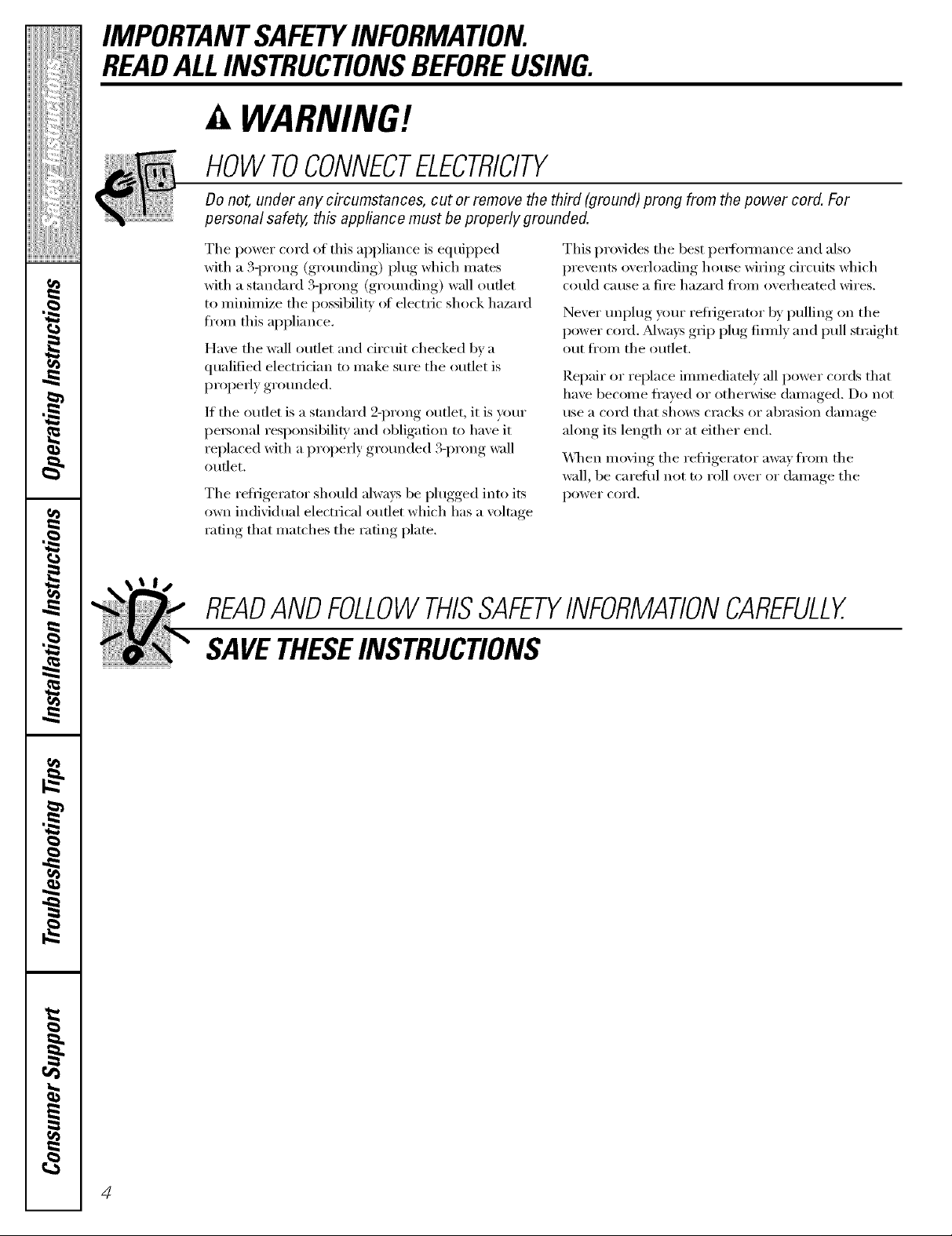
HOWTOCONNECTELECTRICITY
Do not, under any circumstances, cut or remove the third (ground) prong from the power cord. For
personal safe_ this appfiance must be properly grounded.
The power cord of this appliance is equipped
with a 3-prong (grounding) plug which mates
with a standard 3-prong (grounding) wall outlet
to minimize the possibili V of electric shock hazard
fi'om this appliance,
Have the wall outlet and circuit checked by a
qualflied electridan to make sure the outlet is
propedy grounded.
If the outlet is a standard 2-prong outlet, it is _mr
personal responsibili b, and obligation to have it
replaced with a properly grounded %prong wall
outlet.
The refl_igerator, should ahvavs, be I)lugged,, into its
own indixidual electrical outlet which has a xoltage
rating that matches the rating plate.
This provides the best perlimnance and also
I)rexents oxerloading, house wiring circuits which
could cause a fire hazard fl'om oxerheated wires.
NeverIun )lug,,_our refl_igerator, 1)_,I)tilling, on the
I)°wer cord . _Mwavs,,ii,gri) )lug firefly, and pull ,strai_4_t
out fl'om the outlet.
Repair or replace immediately all power cords that
have become fl'ayed or otherwise damaged. Do not
use a cord that shows cracks or abrasion damage
along its length or at either end.
\_]_en moving the refiigerator away from the
wall, be careflfl not to roll over or damage the
power cord.
READANDFOLLOWTHISSAFETYINFORMATIONCAREFULLY.
SAVETHESEINSTRUCTIONS
4
Page 5

Aboutthe temperaturecontrols, gecom
The temperature controls are preset in the factory at 37°F for the
refrigerator compartment and O°Ffor the freezer compartment. Allow
24 hours for the temperature to stabilize to the preset recommended
settings.
The temperature controls can display both the SET temperature
as well as the actual temperature in the refrigerator and freezer.
The actual temperature may vary slightly from the SET temperature
based on usage and operating environment.
Setting either or both controls to OFFstops cooling in both the freezer
and refrigerator compartments, but does not shut off electrical power
to the refrigerator.
J
temperature controls. If this film was not removed during installation,
remove it now.
NOTE: The refrigerator is shipped with protective film covering the
Tochange the temperature, press and release the
WARMER or COLDERpad. Tile SETlight will come
on and tile display will show tile set teml)eramre.
To change tile teml)eratm'e, tap either tile
WARMER or COLDERpad tlntil tile desired
temperature is displayed. Refl'igerator temperatures
can be ac!justed between 34°F and 44°F and tile
fl'eezer teml)eratm'es can be a(!iusted between
-()°F and +6°E
Once tile desired temperature has been set,
tile temperatm'e display will retm'n to tile actual
reflJgerator and fl'eezer temperatm'es alter 5
seconds. Several a(!iusunents may be required.
Each time you a(!iust controls, allow 24 horn's fin" tile
refl_igerator to reach tile temperatm'e you have set.
Toturn thecooling system off, tap tile WARMER pad
fi)r either tile reflJgerator or tile fl'eezer tmtil tile
display shows OFF.To turnthe unit back on,press tile
COLDERpad fin" either tile refl_igerator or fl'eezex:
The SETlight will ilhmfinate on the side you
selected, Then press the COLDERpad again (on the
side where the S_"Tlight is ilhmfinated) and it will
go to tile preset points ot O°Ffi,r tile fl'eezer and
37°Ffln" the reti'igeratox: Setting either or both
controls to OFFsmps cooling in both the fl'eezer
and refl'igerator compartments, but does not shut
off' electrical power to tile reli'igerato_:
PerformanceAir FlowSystem
Tile Perfimnance _M>glow System is designed to
maximize temperatm'e control in tile refligerator
and fl'eezer compartments. This mfique special
teature consists of tile :Mr Tower along tile back
wall ot the refl-igerator and the _dr Tmmel on the
bottom portion of tile fl'eezer rear wall. Placing fi)od
in fl'ont of the louvers on these components will not
affect pettormance. _&dthough tile :Mr Tower
and the ?dr Tmmel can be removed, doing so
will affect temperature ped0mmnce. (For remowfl
instructions, on-line, 24 horns a day, contact us at
ge.com or call 800.GE.CARES. In Canada, contact
us at geappliances.ca or call 1.800.361.3400.)
Page 6

About TurboCool.TM
How it Works
TurboCooY_rapidly cools the refl_igerator
conq)artment in order to more quickly
cool fl)o(ls. Use TurboCool when adding a
large amount ot toed to the refrigerator
compartment, putting away fi)o(ls after they
have been sitting out at room teml)erature
or when putting away warn/leftovers. It can
also be used if the refl_igerator has been
without power for an extended period.
Once acfiw_te(l, the compressor will mrn on
immediately and the tiros will cycle on and
off at high speed as needed tot eight hou_.
The compressor will continue to run until
the refrigerator compartment cools to
approximately 34°F (1 °C), then it will cycle
on and off to maint;fin this setting. _Mter
8 hom_, or if TurboCool is pressed again,
the refrigerator compartment will return
to the original setting.
How to Use
Press TurboCool.The refl_igerat(>r
temperature display will show TO.
_M_.er TurboCoolis complete, the reti_igerator
compartment will return to the odginal
setting.
NOTES:
Therefn)eratortemperaturecannotbechanged
duringTurboCool.
Thefreezertemperatureisnot affectedduring
TurboCool.
Whenopeningtherefrigeratordoordunng
TurboCool,thefanswill continuetorunif they
havecycledon.
Page 7
AboutExpressChill? ge.cem
ExpressChflF_
The ExpmssChill TM feature is a system
of d:uni)e_, a tim and a temi)erature
themfistor.
The controls tot this pan are located at the
top of the refl_igerator with the temperature
controls.
The pan is fighfl)sealed to prexent the pan's
temperatm'e fl'om causing temperatm'e
fltlCttlations in the rest of the refl_igeratm:
How to Use
O Empty the pan. Place the Chill tray in
the pan. Place the items on the tray and
close the pan completely.
O Select the ExpressChilF_pad. The
display and SETlight will come on. Tap
the pad until the light appeax_ next to
the desired setting. Use the chart to
detemfine the best setting to use.
::Ji::To stop a teature betore it is
finished, tap that teatm'e's pad
until no options are selected and
the display is off'.
!i_: During ExpressChill, the displax on
the controls will count down the time
in the cycle.
How to Remove and Replace the Drawer
Toremove: 0 i,ock all four swing locks by rotating
O Pull the drawer out to the stop position, them to the lock i)osifion,
ExpressChi/I
0 _SMIN
• 4sMI.
O Rotate all fimr swing locks to the mdock
position.
I,ifl the fl'ont of the drawer up and out.
Toreplace:
O Make sm'e all Ibm" swing locks are in the
mdock position.
O Place the sides of the drawer into the
drawer supports, making sm'e the swing
locks fit on the drawer slots.
ExpressChilr _Chart
NOTE: Results may vary depending
15 Minutes
5;_ 1 Beverage Can (12 oz)
_:5 2 Small Juice Boxes
(6-8 oz each)
on packaging, starting temperature and other food traits.
30 Minutes
ii:: 2 to 6 B('_erage Cans
(12 oz each)
i_i; 2 Plastic 20 oz Boules
of Beverage
ii:: 4 to 6 Small Juice Boxes
(6-8 oz each)
U 3 Foil Juice Packets
ii:: Wine (7J_0 ml boule)
45 Minutes
i:,_ 2 Liwrs of Beverage
_::: 1/2 Gallon of Juice
i_i: (;eladn-1 package
Page 8
About the water filter. (onsomemodels)
Water FilterCartridge
The water filter cartridge is located in the back upper fight
corner of the refrigerator con/i)artinent.
When to Replace the Filter on Models With a
ReplacementIndicatorLight
There is a replacement indicator light fin" the water filter
carti_idge on the dispense_; This light will mrn orange to tell
wm that you need to replace the filter soon.
The filter cartridge should be replaced when the
replacement indicator light turns red or if the flow of water
to the dispenser or icemaker decreases.
When to Replace the Filter on Models Without a
ReplacementIndicatorLight
The filter cartridge should be replaced every sixmonths
or earlier if the flow of water to the water dispenser or
icemaker decreases.
Removingthe Filter Cartridge
If you are replacing the cartridge, fiI_t remove the old one
by slowly turning it to the left. Do not pull down on the
cam_idge. A small amotmt of water may dil I) down.
Installing the Filter Cartridge
0 ]fxou, are rept lacino;_ a SmartWatercartrid_se, with
an adapte_; mus )e removed befin'e ii trilling the
cartridge. To remove the adapte_; mrn it to the left
about 1/4 turn.
O I,ine up the arrow on the cartridge and the cartridge
holder; Place the top of the new cartridge, uI_ inside the
holdeI; Do not push it up into the holder
O Slowly tm'n it to the right tmfil the filter cartridge stops.
DO NOTOVERTIGHTEN. A_ you turn the cartridge, it will
automatically raise itself into position, The cartridge will
moxe about l/2 ttu'n.
O Rtm water fl'om the dispenser fl)r 3 minutes (about l-1/2
,gall°ns) to clear the s) stem and pre_ent ,Is)uttering,.
0 Press and hold the RESET WATERFILTERpad (on some
models) on the dispenser fin 3 seconds.
NOTE:A i_ewly-instnlled water filter cartridge Ina) cause
water to spurt fi'om the dispensex;
FilterBypassPlug
Ym must use the filter bypass plug when a replacement
filter cartridge is not a\_lilable. The dispenser and the
icemaker will not operate without the filter or filter
bypass plug.
]fw_u are replacing a Water by Culligan cartridge,
leave the adapter in place. This adapter will stay in the
refl_igerator when )'ou replace fimn'e cartridges.
With adapter Withoutadapter
(appearancemay vary)
@ On models without a replacement indicator light,
appl) the month and )ear sticker to the new cartridge
to remind xou to replace the filter in sixmonths.
O Fill the replacement cartridge xfith water fl'om the tap
to allow fi)r better flow fl'om the dispenser immediately
after installation.
Filter Filter""_,, /_
2" f
_/uPgass _ Bypass
Plug_
SmartWater WaterbyCulligan
To use the filter 1Upass plug oil Water by Culligan models,
you llitlst ill'St À'ell/ore the filter adapter tvom the cartridge
holder by tm'nin_ it to the left.
/f you have questions--visit our _,Vebsite
;It ge.(Ol//,
or call 1.800.GE.CARES (1.800.439.9737).
Replacement filters:
To order additional filler cartridges in the United States,
visit our Website at ge.com, or call GE Parts and Accessories,
800.626.2002.
M_F
Suggested Retail $38.95-47.95
Customers in Canada should consult the yellow pages fin.
the nearest Camco Serxice Center:
Page 9

Abouttheshelvesandbins. gecem
Not all features are on all models.
Refrigerator Door Bins and Freezer Door Tilt-Out Bins
Refrigerator bin
Freezer tilt-out bin
LargeBins
The larger refi-igerator door bins and
fl'eezer tilt-out door bins are ac!justable.
To remove: Lift the fl'ont of the bin straight
up, then lift up and out.
Toreplace or relocate: Engage the back side
of the bin in the molded supports on the
doo_: Then push down on the fl'ont of the
bin. Bin will lock in place.
SmallBms
To remove: iift the fl'ont of the bin straioht
up then out.
To replace: Position the bin above the Top freezer bit?
rectangular molded sui)i)orts on the (loo_: ........
Then slide the bin down onto the SUl)port
to lock it in place.
The snuggerhelps prevent tipping, spilling
or sliding of small items stored on the door
shelfi Place a finger on either side ofthe
snugger near the rear and move it back
and fi)rth to fit your needs,
Donotblock CAUTION:
Be careful when
placingitemsinthe
topbin.Makesure
that items do not
blockorfafl into
theicechute.
CAUTION:
Partmustbein
Donot block
placeasshown
forproperice
dispensing.Food
cannotbestored
in thislocation.
l
i
i
Press tab and pull shelf forward
to remove
Slide-Out Spillproof Shelf
The slide-out spillproof shelf allo_vs you
to reach items stored behind othe_. The
special edges are designed to hel I) prevent
spills from dripping to lower shelves.
Toremove:
Slide the shelf out until it reaches the stop,
then press down on the tal) and slide the
shelf straight out.
OuickSpace TM Sheff
This shelf splits in half and slides under
itself fin" storage ot tall items on the shelf
below.
Top freezer bit? (on some models)
Toreplace or relocate:
i,ine the shelf up with the SUl)ports and
slide it into place. The shelf can be
repositioned when the door is at 90 ° or
more. To reposition the shelf, slide the shelf
past the stops and angle downward. Slide
shelf down to the desired position, line up
with the supI)orts and slide into place.
Make sure you push the shelves all the wayback
in before you dose the doo_
On some models, this shelf cannot be used
in the lowest position.
This shelf can be removed and replaced
or relocated just like Slide-Out Spillproof
Shelves.
Page 10

Abouttheshelvesandbins.
Not all features are on all models.
Freezer Baskets
To remove, push the 1)asket all the way to the
back of the freezei: i.ifi up until the back
pins are disengaged, i,ifi the entire basket
up and pull ()tlt.
Makesureyoupushthebasketsall the wayback
in beforeyouclosethe doo_
i ¸ ()/Q( )
i _ _ iI
Slide-Out Freezer Shelves
To remove, slide ()tit to the stop posit.ion,
lifi the fl'ont past the stop position and
slide ()tit,
Fixed Freezer Shelves
There are two b'pes of fixed
fl'eezer shelves.
Toremovethistypeofshelf"
0 I,ift the shelf up at the left side.
Bring the shelf ()tlt,
Toremovethistypeofshelf"
0 i,ift up the left side of the shelf and
slide it left into the center of the shelf
suI)ports.
@ Rotate the right side of the shelf up
and ()tit of the shelf supports.
Makesureyoupushtheshelvesall thewayback
in beforeyouclosethe doo_
NOTEFORDISPENSERMODELS:/nordertotake
fu//advantageofthetilt-outicebin,on/}/storeitems
ontheshelfbelowtheicebinthatarenotallerthan
the/owestpointonthebin.
10
Door Wine/Beverage Rack (onsomemodels)
This rack holds up to 5 cans, one bottle of
wine or one 2-liter bottle of soda.
The rack hangs fl'om the sides of the
dairx bin.
To remove:
Empb the wine/beverage rack.
Holding the bottom of the dairy bin,
lift the fl'ont straight up, then lift up
_lIl(l o/It.
To detach the rack fl'om the daiI T bin,
pull the rack's side wires out of the
holes on each side of the dairy bin.
To replace:
Reattach the rack to the sides
of the bin.
Engage the back side of the bin in
the molded supports on the dooI:
Then push down on the ti'ont of the
bin. The bin will lock into place.
/
Page 11
Abouttherefrigeratordoors, gecom
Refrigerator Doors
When the door is only partially open,
it will automatically close.
Beyond flTisstop flTedoor will stay open.
I
The reti_igerator (loo_ may feel (liflerent
than the ones you are used to. The special
door opening/closing teatuI'e I/lakes StlI'e
the (loo_s close all the way and are securely
sealed.
When opening and closing the door you
will notice a step position. If the door is
opened past this step point, the door will
remain open to allow vou to load and
unload fi_od more easily. _,\]/ell the door
is only partially open, it will automatically
close.
Door Alignment
If doo_ are une',en, a(!iust the reti_igerator
dooi:
Using a 7/16" wrench, turn the door
ac!iusfing screw to the right to raise the
doo_; to the left to lower it. (A nylon
i)lug, imbedded in the threads of the
pin, prevents the pin fl'om turning
unless a wrench is used.)
The resistance you teel at the stop
position will be reduced as the door
is loaded with fi)od.
O _Mter one or two turns of the wrench,
oi)en.... and close the refl_igerator, door
and check the alignment at the top of
the (loo_.
11
Page 12

Aboutthecrispers andpans.
Not all features are on all models.
Fru# and Vegetable Crispers
Excess water that may accunmlate in tile
bottom of tile drawers should be wiped (h_':
On some models, tile l)ottom drawer has
fitll extension slides that allow fitll access
to tile (h'awet:
HI _ LO
o
Adjustable Humidity Crispers
Slide tile control all tile _w_'to tile HI setting
to provide high humidly' recommended tor
most vegetables.
Convertible Deli Pan
Tile convertible deli pan has its own cold
air duct to allow a streain ot cold air fl'om
tile ti'eezer compartment or fi'esh toed
compartment to flow to tile pan.
The variable temperature control regulates
tile air flow fl'om tile Climate Keeper:
Aboutcrisperremoval
Slide tile control all tile way to tile LO
,settino_ to proxide lower humidi_ lex els
recommended fi)r most fl'uits.
Set tile control to tile coldest setting to
store fresh tlleats.
Set tile control to coldto convert tile pan
to nomml refi_igerator temperature and
provide extra vegetable storage space. The
cold air duct is turned off. Variable settings
between these extremes can be selected.
Not all features are on all models.
Crisper Removal
Crispers can easily be remo\vd by pulling
tile drawer straight out and lifting tile
(hawer up and over tile stop location.
12
If the door prevents you ti'om taldng out
tile dl'awetN, fitNt ttT to telllOVe tile door
bins. If this does not offer enough
clearance, tile refi]gerator will need to
be rolled flwward until tile door opens
enough to slide tile (hawel_ out. In some
cases, when you toll tile refligetator out,
you will need to mo\e tile refl_igerator
to the left or fight as you roll it out.
Page 13
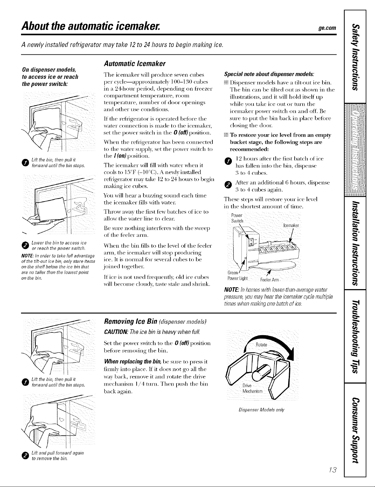
Abouttheautomaticicemaker, ge.cem
A newly installed refrigerator may take 12to 24 hours to begin making ice.
Automatic Icemaker
On dispenser models,
to access ice or reach
the power switch:
o Lift flTebin, then pull it
forward until the bin stops.
Lower thebin to access ice
or reach the power switch.
NOTE:In order to take full advantage
of the tilt-out ice bflT,only store items
on the shelf below the ice bfl7that
are no taller than the Iowest pofl?t
on the bin.
The icemaker will produce seven cubes
per cycle'---aI)proximately 100-130 cubes
in a 94-hour period, depending on fl'eezer
COilll)ai'tlllent teilll)ei'attli'e _ i'OOill
teil/l)ei'attli'e _ ntlillber of door ol)enings
and other use conditions.
If the reti_igerator is operated betore the
water connection is made to the icemake_;
set the power switch in the 0 (off) position.
When the refl-igerator has been connected
to the water SUl)ply, set the power switch to
the I (on)position.
The icemaker will fill with water when it
cools to 15°F (-10°C). A newly installed
refi_igerator may take 12 m 24 hotu_ to begin
making ice cubes.
You will hear a buzzing sound each time
the icemaker fills with water:
Throw awm the first tew batches of ice to
allow the water line to clem:
Be sure nothing interteres with the sweep Icemaker
of the teeler am_.
When the bin fills to the level _ffthe teeler
ram, the icemaker will stop producing
ice. It is nomml tot several cubes to be
joined together.
If ice is not used fi'equenfl}; old ice cubes
will become cloudy, taste stale and shrink.
Special note about dispenser models:
::Ji::Dispenser models have a tilt-out ice bin.
The bin can be tilted out as shown in the
illustrations, and it will hold itself up
while you take ice out or turn the
icemaker power switch on and otE Be
sure to put the bin back in place betore
closing the doo_:
::Ji::To restore your ice level from ma empty
bucket stage, the followh_g steps are
recommended:
O 12 hom_ after the fi_t batch of ice
has tidlen into the bin, dispense
3 to 4 cubes.
@ _Mter an additional 6 hom_, dispense
3 to 4 cubes a ,ain
These steps will restore your ice level
in the shortest amount (ff time.
p0werLight FeelerArm
NOTE."Inhomeswith lower-than-averagewater
pressure,you mayhear the icemakercycle multiple
times whenmaklbgonebatch of ice.
o Lift flTebin, then pull it
forward until the bin stops.
o Liftandpull forwardagain
toremovethebin.
Removing Ice Bin (dispensermodels)
CAUTION: The ice bin is heavy when full.
Set the power switch to the 0 (Off)position
befi)re remoxing the bin.
When replacing the bin, be sure to press it
fire,l} into place. If it does not _ooall the
wm back remoxe it and rotate the (lrixe
mechanism 1/4 ttlFn. Then push the bin
back again.
Dispenser Models only
13
Page 14
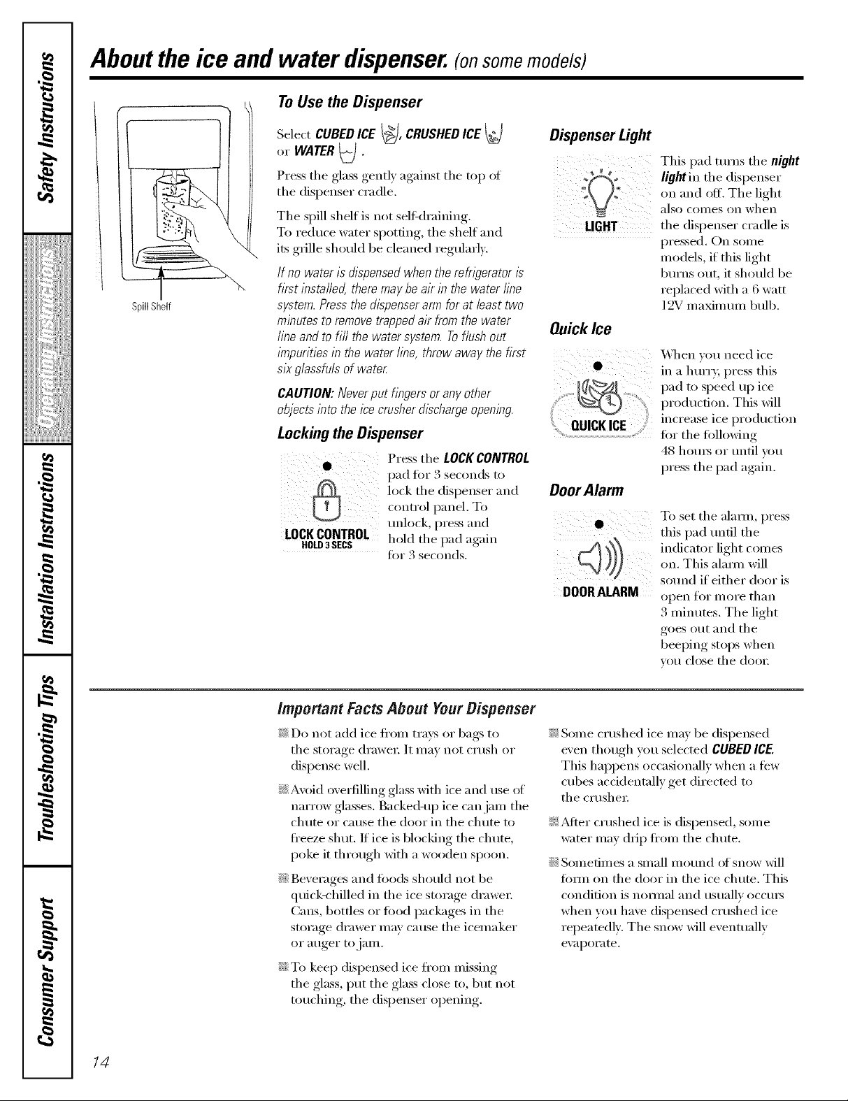
Aboutthe ice and water dispenser.(onsomemodels)
ToUsetheDispenser
SpillShelf
Select CUBED ICE I_], CRUSHEDICE t_}
or WATER l_I
r
Press tile glass gentl) against tile top ot
the dispenser cradle.
The spill shelf is not self-draining.
To reduce water spotting, the shelf and
its grille should be cleaned regularl).
If no water is dispensed when therefrigerator is
first instafled, there may be air in the water fine
system. Press the dispenser arm for at least two
minutes to remove trapped air from the water
line and to tiff the water system. Toflush out
impurities in the water fine, throw away the first ..................................................................\,\lien you need ice
six g/assfuin of water Q in a hllrrv; press tills
x
CAUTION:Neverput fingersoranyother
objectsinto theicecrusherdischargeopening.
Lockingthe Dispenser
• PresstheLOCKCONTROL
lock the dispenser and
p.dfo, seco.dsto
c,,ntrol })anel. To
unlock, press and
LOCKCONTROL hold tile )ad again
HOLD3SECS l i
for 3 seconds.
Dispenser Light
;)!
I!i II
LIGHT
QuickIce
i ¸ _
QUICKICE
DoorAlarm
DOORALARM
This pad turns tile night
light in tile dispenser
on and off. The light
also COilleS on when
tile dispenser cradle is
pressed. On some
models, if this light
b/1Yns O/l[, it should be
replaced with a 6 watt
12V maximmn bull).
pad to speed up ice
production. This _611
increase ice production
for the fi)llo\6ng
48 hom_ or until you
press the pad again.
To set the ;11;11111, pl'ess
this pad tmti] the
indicat(n light c(mms
on. This al;mu will
sound if either door is
open Jk)i" l//oYe thin?
3 minutes. The light
goes out and tile
beeping stops when
VOt/close the door.
14
important Facts About Your Dispenser
_: Do not add ice fl'om trays or bags to
tile storage drawer It may not crush or
dispense well.
_: Avoid ove_tilling glass with ice and rise (ff
narrow glasses. Backed-up ice can jam tile
chute or cause tile door in tile chute to
freeze shut. If ice is blocking the chute,
poke it through with a wooden spoon.
iJi::Beverages and fi)ods should not be
quick-chilled in the ice storage (h'awe_:
Cans, bottles or fi)od packages in tile
storage drawer may Ca/Ise tile icemaker
or auger to jam.
iJi::To kee I) dispensed ice fl'om missing
the glass, put the glass close to, but not
touching, the dispenser opening.
_: Some crushed ice may be dispensed
even though you selected CUBEDICE.
This hal)pens occasionall)' when a few
cubes accidentally get directed to
tile crushe_:
?_:AJier crushed ice is dispensed, some
water may drip ti'om tile chute.
iJi::Sometimes a small me/rod of snow will
from on tile door in tile ice chute. This
condition is nomml and usually occm's
when wm have dispensed crushed ice
repeatedly. Tile snow will eventually
eV_ll)OI'ilte.
Page 15

Careandcleaning of the refrigerator.
Cleaning the Outside
The dispenser drip area, beneath tl_e grille,
should be wiped (h_'. _\'ater leit in this area
may leave deposits, Remove the deposits by
Dispenser drip area.
adding undiluted vinegar to the well. Soak
tmtil the deposits disappear or become
loose enotlgh to Yinse aW;IV.
The dispenser cradle. Betore cleaning, lock
the dispenser by pressing and holding the
LOCKCONTROLpad tot :4seconds. Clean
with wam_ water and baking soda
solution--about a tablespoon (l 5 ml) of
baking soda to a qt:lart (l liter) of water:
Rinse thoroughly and wipe d_v
The door handles and trim.Clean with
a cloth danq)ened with soap)' wateI:
Dry with a soft cloth.
ge.com
The stainless steel panels and door handles
(on solne Inodels) can be cleaned with
a commercially available stainless steel
cleane_: A spra)_on stainless steel cleaner
works best.
Do not use appliance wax or polish
on the stainless steel,
Keep theoutsideclean.Wipe with a clean
cloth lightly dampened Mth kitchen
appliance wax or miM liquid dish detexgent.
Dry and polish with a clean, soft cloth.
Donot wipetherefn_?eratorwith a soileddish
cloth orwet towel Thesemay&ave aresidue
that canerodethepaint.Donot usescouring
pads,powderedcleaners,bleachorcleaners
containingbleachbecausetheseproductscan
scratchand weakenthepainthblsh.
I
_!!iiii,,_i<iiiii_i:il
ii_iiiii_iiii}ii;i
iii!iiiiii_i_ii{ii¸
Cleaning the Inside
Tohelp prevent odors, leave an open box of
baking soda in the fl'esh fi)od and fl'eezer
COil] I)_1 EtlIIexlts,
Unplug the refrigerator before cleaning. If this
is not practical, wring excess moisture out
of sponge or cloth when cleaning arotmd
switches, lights or controls.
Use waIIn water and baking soda solution--
about a tablespoon (l 5 ml) ol baking soda
to a quart (l liter) ofwam_: This both
cleans and neutralizes odors. Rinse and
wipe (h'v:
Use of any cleaning solution other than that
which is recommended, especially those that
contain petroleum distillates, can crack or
damage the interior of the refrigerator.
Avoid cleaning cold glass shelves with hot water
because the extreme temperature difference
may cause them to break. Hand& glass shelves
carefull_z Bumping temperad g/ass can cause
it to shatter
Donot washanyplasticrafngeratorparts
in thedishwasher
Thechili/thawtrayis dishwashersafe.
g,.
g
g
}
15
Page 16

Careand cleaning of the refrigerator.
Behind the Refrigerator
Be caretul when moving the refl_igerator
away fl'om the wall. MI types of floor
coverings can be danlaged, particularly
cushioned coverings and those with
elllbossed S/lI]_lces.
Pull the reflJgerator straight out and returi_
it m position by pushing it straight in.
Moving the refl_igerator in a side direction
Inay result in danmge to the floor cox'ering
or refl_igeratoi:
Preparing for Vacation
For long ;_lcations or absences_ rei//ove
tood aim uI_plug the refligeratoi: Clean the
interior with a baking soda solution of one
tablespoon (15 nil) of baking soda to one
quart (1 liter) of watei; i,eave the dooi_
open.
Set the icemaker power switch to the 0 (ol_J
position and shut off the water supply to
the i'efl_igelatoi:
When pushing the refrigerator back, make sure
you don't rofl over the power cord or icemaker
supply line.
If the temperatm'e can drop below fl'eezing,
have a qualified servicer drain the water
supply systeln to prevent serious propert}'
damage due to flooding.
Preparing to Move
Secm'e all loose items such as shelves and
drawe_ by roping them secm'ely in place
to prevent damage.
XA]mn using a hand truck to move the
refl_igeratoi; do not rest the fl'ont or back
ot the refl_igerator against the hand truck.
This could damage the reffigeratm: Handle
only fl'om the sides of the reffigeratm:
Be sure the refngerator stays in an upright
position during moving.
16
Page 17
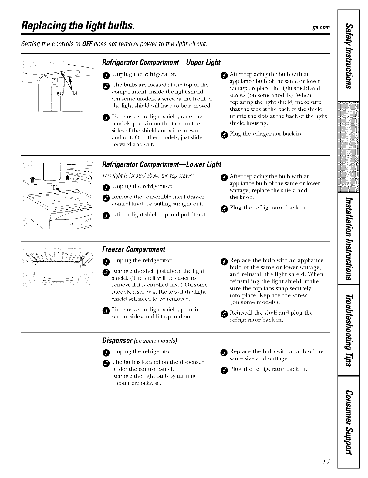
Replacingthe lightbulbs, gecom
Setting the controls to OFF does not remove power to the light circuit.
Refrigerator Compartment--Upper Light
.............0 O
Unplug the refligerator.
The bulbs are located at the top ot the
compartment, inside the light shield.
On some models, a screw at the fl'ont of
the light shield will have to be removed.
To remove the light shield, on some
@
models, press in on the tabs on the
sides of the shield and slide torward
and out. On other models,just slide
fin'ward and out.
@
Refrigerator Compartment--Lower Light
This hght is located above the top drawe_
0 /-'rnplug the refl_igerato_:
0 Remoxe the comertible meat drawer
control knob b) pulling straight out.
lilt the light shield III) and pull it out.
O ,Mter replacing the bulb xfith an
0 Plug the refrigerator back in.
Freezer Compartment
0 Unplug the refligerator.
0 Remoxe the shelf just aboxe the light
shield. (The shelf will be easier to
remoxe if it is emptied fi_st.) On some
models, a screw at the top of the light
shield will need to be remoxed.
To remoxe the light shield, press in
on the sides, and lift up and out.
0
,Mier replacing the bulb with an
appliance bulb ot the same or lower
wattage, replace the light shield and
scrm_:s (on some models). When
replacing the light shield, make sure
that the tabs at the back ot the shield
fit into the slots at the back of the light
shield housing.
Plug the refl_igerator back in.
appliance bulb of the sanle or lower
wattage, replace the shield and
the knob.
Replace the bull) with an appliance
bulb of the same or lower wattage,
and reinstall the light shield. When
reinstalling the light shield, make
sure the top tabs snap secm'elv
into place. Replace the screw
(on some models).
Reinstall the shelf and plug the
refrigerator back in.
Dispenser (on some models)
0 /-'rnplug the refligerator.
0 The bulb is located on the dispenser
trader the control panel.
Remoxe the light bulb b) tm'ning
it cotmterclockwise.
O Replace the bulb with a bulb of the
same size and wattage.
Plug the refrigerator back in.
/7
Page 18

Trimkits anddecoratorpanels.
For CustomStyM °'models
Read these instructions completely and carefully.
BeforeYouBegin
Some models are equipped with trim kits that aflow you to instafl door panels. You can order
pre-cut black, white, bisque or stainless steel decorator panels from GE Parts and Accessories,
800.626.2002, or you can add wood panels to match your kitchen cabinets.
Panels less than 1/4" (6 mm) thick
When installing wood panels less than ]/4" (6 mm) thick, you need to create a filler panel, such as ]/8"
cardboard, that Mll fit between the ti_ce of the door and the wood panel. If you are installing the pre-cut
decorator panels, pre-cut filler panels are included in the kit. The combined thickness of the decoraun"
or wood panel and the filler panel should be 1/4" (6 ram).
Panels1/4"thick oriess
1/4"max
3/4" (19 mm) or Raised Panel
A raised I)anel desion_ screwed or ,glued to a 1/4" (6 ram) thick backing, or a 3/4" ( ] cJram) routed board
can be used. The raised portion of the panel must be thbcicated to pe_nit clearances of at least 2" (5.1 cm)
from the handle side for fingertip clearance.
Panels thicker than 1/4" (6 ram), up to 3/4 (l .) ram) max, will _equue that the outer :)/16 (8 ram) of
panel perimeter be no thicker than 1/4" (6 ram).
Weight limitations for custom panels:
Fresh Food38Ibs. (17kg)max.
Freezer Door 28/bs. (13kg) max
Panelsthickerthan1/4"(6ram)
6"(8ram)
1/4"(6ram}max
3/4" 119Into}
f
2"(5.1 cm)
Clearance
HandleSide
Appearance
Panel
1/4"(6ram)
kBacking
_iiiltor
Door
18
Page 19
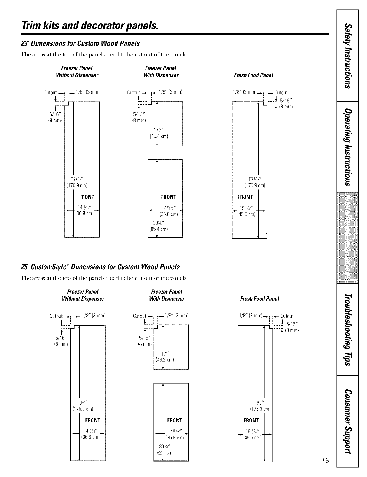
Trimkits anddecoratorpanels.
23"Dimensions for Custom Wood Panels
The areas at the top of the panels need to be cut out of the panels.
Freezer Panel Freezer Panel
Without Dispenser With Dispenser
FreshFoodPanel
Cutout .-_1 _- 1/8"(3 ram)
_.. i I
.... J
Cutout "-'I F"-1/8"(3 ram)
',
i i
t
5/16"
(8 ram)
/8rara,| /
/ 177/_"
1(45i4era'
67%Z'
(170.9 cra)
FRONT
141%Z'
'(36.8 cra)"
25"CustomStyleTM Dimensions for Custom Wood Panels
i FRONT
141%2" ..,
(36.8 cra)
33%"
(85.4 cm)
1/8"(3 ram).-,.: :.,,- Cutout
" "---} 5/16"
I..
""} (8 rara)
67%2"
(170.9 cra)
FRONT
1915/32"
"(49.5 cra)' _
The areas at the top of the panels needtobe cutoutof the panels.
FreezerPanel FreezerPanel
WithoutDispenser With Dispenser
Cutout "-'I _"- 1/8" (3 ram)
.... --I
''
i !
Cutout --,-, ,--1/8" (3 ram)
',
i i
t
5/16"
(8 mm)
69"
(175.3 cm)
FRONT
1415/32"
"(36.8 cra) _
(6rara/| /
j 17"
1(43i2cra)
i FRONT
(92.0 cra)
15 "
14/_2 ,.,
(36.8 cra)
361A"
{
FreshFoodPanel
1/8"(3 rara).-,,-f :_,- Cutout
" "----_ 5/16"
L ---} (8 rara)
69"
(175.3cra)
FRONT
191%2"
"-(49.5 cra)"--"
19
Page 20

Insertingthedoorpanels.
Read these instructions completely and carefully.
0 Insert the Freezer Panel and FreshFood Panel
Carefully push the fi'eezer panel in until it slides If your model has a (lispense_; this step only applies
into the slot behind the door handle. Push the filler to the fl'esh fl_od panel and top fl'eezer panel.
panel (required with some door panels) in behind
the decorator panel, Repeat fin" fl'esh fl)od panel,
0 Insert the Bottom Freezer Panel (ondispenser models).
Carefull_ push the panel in until it slides into the (required with some door panels) in behind the
slot behind the door handle, Push the filler panel decorator panel,
Attach the TopTrimon the Freezer and Fresh Food Doors.
The Top Trim can be tound inside the reii_igerator each (loo_; Hand tighten only: Make sure that the
compartment, top of each panel fits snugly behind the lip of the
With a T-20 Torxdrive_; attach the Top Trim, using Top Trim.
two screws on each Top T_im piece, to the top oI
Cut-Out
SideTrim
t
20
Page 21

Insertingthedoorpanels.
O Install the Side Trim.
These pieces are tucked inside the reti_igerator
door handle.
Donot removethe protectivefilm on theoutsideof
theSideTrimuntil theSideTrimis installed.
Fit the bottom of the Side Trim under the
Bottom Trim as illustrated.
Hold the Side Trim against the fl'ont fl_ce of the
decorator panels and fit the Side Trim under
the Top Trim. Make sure the magnetically attached
Side Trim is fitted correctly and that you are
satisfied with the appearance of all the parts.
2/
Page 22

Installation
Refrigerator
Instructions
Questions? Call 800.GE.CARES (800.432.2737) or Visit our Website at: ge.com
I
BEFORE YOU BEGIN
Read these instructions completely
and carefully.
• iMPORTANT - Savethese
instructions for local inspector's use.
• iMPORTANT - Observeall
governing codes and ordinances.
Note to Installer - Be sure to leave these
instructions with the Consumer.
Note to Consumer - Keep these
instructions for future reference.
Skill level - Installation of this appliance
requires basic mechanical skills.
Completion time - Refrigerator Installation
Proper installation is the responsibility of
the installer.
In Canada, call 1.800.361.3400 or Visit our Website at: geappliances.ca
30 minutes
Water Line installation
30 minutes
Models 22, 23, 25, 26, 27 & 29
PREPARATION
WATER SUPPLY TO THE ICEMAKER
If the refrigerator has an icemaker, it will have
to be connected to a cold water line. AGE
water supply kit (containing tubing, shutoff
valve, fittings and instructions) is available
at extra cost from your dealer, by visiting
our Website at go.corn (in Canada at
geappliances.ca) or from Parts and
Accessories, 800.626.2002 (in Canada
1.888.261.3055).
TOOLS YOU WILL NEED
3/8" and 5/16" Socket 1/2" and 7/16" Wrench
I
Product failure due to improper installation
is not covered under the Warranty.
if the refrigerator has already been installed,
remove the base grille (see Step 2 in Moving
the Refrigerator), then skip to Step 5 in
Installing the Refrigerator.
Plastic Putty Knife
Phillips Head Screwdriver
22
Page 23
Installation instructions
MOVING THE REFRIGERATOR
[] LOADING THE RERIGERATOR
ONTO A HAND TRUCK
Leave all tape and door pads on doors
until the refrigerator is in its final location.
To move the refrigerator, use a padded
hand truck. Center the refrigerator on the
hand truck and secure the strap around
the refrigerator. DO NOT OVERTIGHTEN
THE STRAP.
If the refrigerator must go through
any entrance that is less than 38"
wide, the doors must be removed.
Proceed to Step 3.
DO NOT remove the handles.
If all entrances are more than
38" wide, skip to Installing
the Refrigerator.
[] DISCONNECT THE WATER
COUPLING (on some models)
If the refrigerator has a water dispenser,
there is a water line from the cabinet into
the bottom hinge on the freezer door that
must be disconnected.
To disconnect, push in on the white collar
of the coupling and pull out the tubing.
White collar
[] REMOVE THE BASE GRILLE
Remove the grille by removing the two
Phillips head screws.
Bottom
freezer
hinge
23
Page 24

Installation instructions
MOVING THE REFRIGERATOR (CONT.)
[] DISCONNECT THE POWER
COUPLING (on some models)
If the refrigerator has a water dispenser,
there is a power line (harness) from the
cabinet into the bottom hinge on the
freezer door that must be disconnected.
To disconnect pull apart at the coupling.
Bottom _ _ L_J o "_../_L/
freezer / _" _J'-="=--=-"=--=
hin
DISCONNECT THE ELECTRICAL
[]
CONNECTORS (on some models)
If the refrigerator has a refreshment
center, there are electrical connectors
(harnesses) from the cabinet into the
bottom hinge on the refrigerator door
that must be disconnected.
To disconnect, pull apart each connector.
[] CLOSE THE FREEZER AND
REFRIGERATOR DOORS
[] REMOVE THE FREEZER DOOR
[] Remove the freezer door top hinge cover
(if equipped) by either squeezing it and
pulling it up or by prying it off with a
plastic putty knife.
[] Remove the two 5/16" or 1/8" hex head
screws, then lift the hinge straight up to
free the hinge pin.
5/16" or 1/8" hex head
Bottom
refrigerator
hinge
[] Open the freezer door to 90. °
J
J
90 °
24
Page 25
Installation instructions
[]
REMOVE THE FREEZER DOOR
(cont.)
[]
As one person slowly lifts the freezer door
up and off the bottom hinge, the second
person should carefully guide the water
line and power line (harness) through the
bottom hinge.
_
90°
[] REMOVE THE REFRIGERATOR
DOOR (cont.)
[] Remove the two 5/16" or 1/8" hex head
screws, then lift the hinge straight up to
free the hinge pin.
5/16" or 1/8" hex head
<
[] Open the refrigerator door to 90. °
[] Set the door on a non-scratching surface
with the inside up.
[] REMOVE THE REFRIGERATOR
DOOR
[] Remove the refrigerator door top hinge
cover (if equipped) by either squeezing it
and pulling it up or by prying it off with
a plastic putty knife.
_ H
90 °
25
Page 26
Installation Instructions
MOVING THE REFRIGERATOR (CONT.)
[]
REMOVE THE
REFRIGERATOR DOOR (cont.)
[]
Lift the refrigerator door up and off the
bottom hinge.
If the refrigerator has a refreshment
center, one person should slowly lift the
door up and off the bottom hinge and the
second person should carefully guide the
electrical lines (harnesses) through the
bottom hinge.
[] REPLACING THE DOORS
To replace the doors, simply reverse
steps 3 through 8,
However, please note the following:
• When lowering the doors onto the
bottom hinges, make sure the second
person carefully guides the tube and
harnesses through the holes in the
hinges.
• When connecting the water line, make
sure you insert the tubing all the way
to the mark.
\ _ ........
90 °
Refreshment Center Models Only
[] Set the door on a non-scratching surface
with the inside up.
Mark
• Do not pinch the tubing and harnesses
when placing the doors on the bottom
hinges.
• When connecting the power line and
the electrical lines (refreshment center
models only), be sure that the
connectors are seated together fully.
26
Page 27
Installation Instructions
INSTALLING THE REFRIGERATOR
REFRIGERATOR LOCATION
• Do not install the refrigerator where the
temperature will go below 60°F (16°C)
because it will not run often enough to
maintain proper temperatures.
• Do not install the refrigerator where the
temperature will go above 100°F (37°C)
because it will not perform properly.
• Install it on a floor strong enough to
support it fully loaded.
CLEARANCES
Allow the following clearances for ease
of installation, proper air circulation and
plumbing and electrical connections:
22', 23' (33" wide),
23"/25" CustomStyle TM 25', 26', 27', 29'
Sides 1/8" (4 mm) 1/8" (4 mm)
Top 1" (25 mm) 1" (25 mm)
Back 1/2" (13 mm) 1" (25 mm)
DIMENSIONS AND SPECIFICATIONS
(for 23" CustomStyle TM models)
701/4" (178.4cm
o
36"
(91.4cm)
DIMENSIONS AND SPECIFICATIONS
(for 25" CustomStyle TM models)
DIMENSIONS AND SPECIFICATIONS
Water Electrical
_'_3/4"(19 ram)Airspace
(1/2"[13 ram]Gap+
1/4" [6ram]WallPlates)
25" (83.5cm)
Countert0p
' J'L '
........2 2........
721A" (183.5cm)_
o
o
_721/4 rl (183.5 cm) required for full adjustment
of mobility wheels. If cabinets installed
above refrigerator have doors that are
flush to the top of the opening for the
refrigerator, then an additional 1/8'I may be
required to provide clearance for cabinet
doors to open freely.
36"
(91.4cm)
27
Page 28
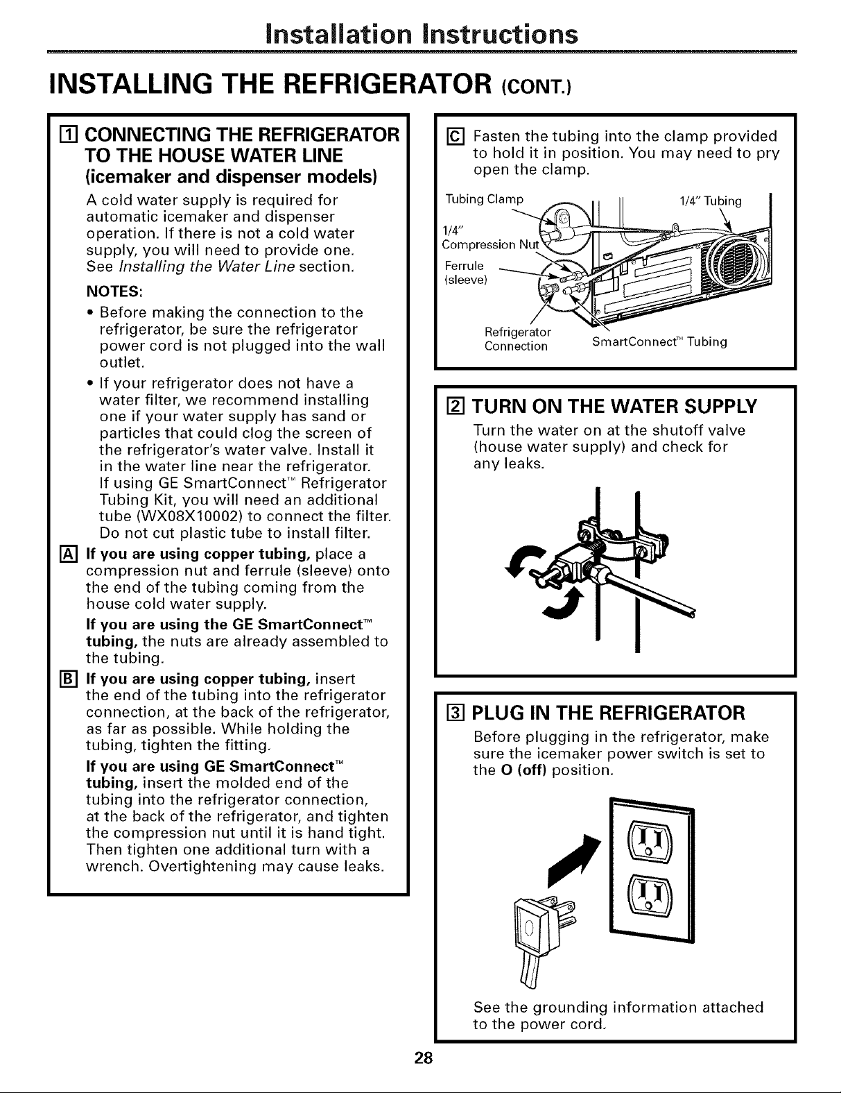
Installation Instructions
INSTALLING THE REFRIGERATOR (CONT.)
[]
CONNECTING THE REFRIGERATOR
TO THE HOUSE WATER LINE
(icemaker and dispenser models)
A cold water supply is required for
automatic icemaker and dispenser
operation. If there is not a cold water
supply, you will need to provide one.
See Installing the Water Line section.
NOTES:
Before making the connection to the
refrigerator, be sure the refrigerator
power cord is not plugged into the wall
outlet.
• If your refrigerator does not have a
water filter, we recommend installing
one if your water supply has sand or
particles that could clog the screen of
the refrigerator's water valve. Install it
in the water line near the refrigerator.
If using GE SmartConnect TMRefrigerator
Tubing Kit, you will need an additional
tube (WX08X10002) to connect the filter.
Do not cut plastic tube to install filter.
[]
If you are using copper tubing, place a
compression nut and ferrule (sleeve) onto
the end of the tubing coming from the
house cold water supply.
If you are using the GE SmartConnect TM
tubing, the nuts are already assembled to
the tubing.
[]
If you are using copper tubing, insert
the end of the tubing into the refrigerator
connection, at the back of the refrigerator,
as far as possible. While holding the
tubing, tighten the fitting.
If you are using GE SmartConnect TM
tubing, insert the molded end of the
tubing into the refrigerator connection,
at the back of the refrigerator, and tighten
the compression nut until it is hand tight.
Then tighten one additional turn with a
wrench. Overtightening may cause leaks.
[] Fasten the tubing into the clamp provided
to hold it in position. You may need to pry
open the clamp.
Tubing Clamp 1/4" Tubin
1/4"
Compression
Ferrule
(sleeve)
Refrigerator
Connection
[] TURN ON THE WATER SUPPLY
Turn the water on at the shutoff valve
(house water supply) and check for
any leaks.
[] PLUG IN THE REFRIGERATOR
Before plugging in the refrigerator, make
sure the icemaker power switch is set to
the O (off) position.
SmartConnect TMTubing
28
See the grounding information attached
to the power cord.
Page 29

Installation instructions
[] PUT THE REFRIGERATOR
IN PLACE
Move the refrigerator to its final location.
[] LEVEL THE REFRIGERATOR
The refrigerator can be leveled by
adjusting the rollers located near the
bottom hinges.
Rollers have three purposes:
• Rollers adjust so the door closes easily
when opened about halfway. (Raise the
front about 5/8" [16 mm] from the floor.)
• Rollers adjust so the refrigerator is
firmly positioned on the floor and does
not wobble.
• Rollers allow you to move the
refrigerator away from the wall for
cleaning.
To adjust the rollers on 22", 23" (33" wide),
25", 26", 27" and 29" models:
• Turn the roller ,) II II
clockwise to
raise the
Raise
[] LEVEL THE REFRIGERATOR
(cont.)
To adjust the
rollers on 23"/25"
CustomStyle TM
models:
Turn the front roller
adjusting screws
clockwise to raise
the refrigerator,
counterclockwise
to lower it. Use a 3/8" hex wrench with
extension, or an adjustable wrench.
These models also have rear adjustable
rollers so you can align the refrigerator
with your kitchen cabinets. Use a 3/8" hex
wrench with extension to turn the screws
for the rear rollers--clockwise to raise the
refrigerator, counterclockwise to lower it.
......... J L___
Roller adjusting screws
[] LEVEL THE DOORS
Adjust the refrigerator door to make the
doors even at the top.
To align:
[]
Using a 7/16" wrench, turn the door
adjusting screw to the right to raise the
door, to the left to lower it.
NOTE:
A nylon plug, imbedded in the threads
of the pin, prevents the pin from turning
unless a wrench is used.
[]
After one or two turns of the wrench,
open and close the refrigerator door and
check the alignment at the top of the doors.
Doors should be even at top
refrigerator, _(
adjusting screws __
to lower it. Use
a 3/8" hex socket
or wrench, or
counterclockwise .__d_,
an adjustable
wrench. Roller adjusting screw
29
Page 30
Installation Instructions
INSTALLING THE REFRIGERATOR (CONT.)
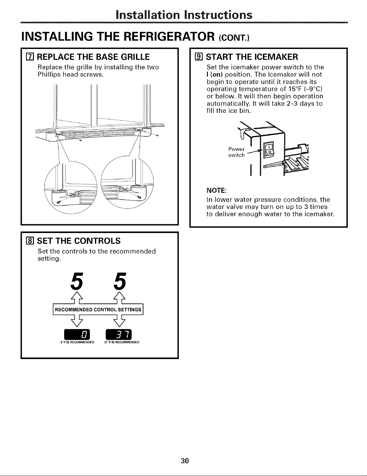
[] REPLACE THE BASE GRILLE
Replace the grille by installing the two
Phillips head screws.
[] START THE ICEMAKER
Set the icemaker power switch to the
I (on) position. The icemaker will not
begin to operate until it reaches its
operating temperature of 15°F (-9°C)
or below. It will then begin operation
automatically. It will take 2-3 days to
fill the ice bin.
Pow
switch - I
NOTE:
In lower water pressure conditions, the
water valve may turn on up to 3 times
to deliver enough water to the icemaker.
[] SET THE CONTROLS
Set the controls to the recommended
setting.
5 5
[.EOOMME.OEOCO.T.O'SETT..OS]
0 *FIS RECOMMENDED 37 1= IS RECOMMENDED
30
Page 31

Installation instructions
iNSTALLiNG THE WATER LiNE (ICEMAKER &DISPENSERMODELS)
BEFORE YOU BEGIN
Recommended copper water supply kits are
WX8X2, WX8X3 or WX8X4, depending on the
amount of tubing you need. Approved plastic
water supply lines are GE SmartConnect TM
Refrigerator Tubing (WX08X10002,
WX08Xl0006, WX08X10015 and
WX08X10025).
When connecting your refrigerator to a GE
Reverse Osmosis Water System, the only
approved installation is with a GE RVKit. For
other reverse osmosis water systems, follow
the manufacturer's recommendations.
If the water supply to the refrigerator is from
a Reverse Osmosis Water Filtration System
AND the refrigerator also has a water filter,
use the refrigerator's filter bypass plug. Using
the refrigerator's water filtration cartridge in
conjunction with the RO filter can result in
hollow ice cubes and slower water flow from
the water dispenser.
This water line installation is not warranted
by the refrigerator or icemaker manufacturer.
Follow these instructions carefully to
minimize the risk of expensive water damage.
Water hammer (water banging in the pipes)
in house plumbing can cause damage to
refrigerator parts and lead to water leakage
or flooding. Call a qualified plumber to correct
water hammer before installing the water
supply line to the refrigerator.
To prevent burns and product damage, do not
hook up the water line to the hot water line.
If you use your refrigerator before connecting
the water line, make sure the icemaker power
switch is in the O (off} position.
Do not install the icemaker tubing in areas
where temperatures fall below freezing.
When using any electrical device (such as a
power drill) during installation, be sure the
device is double insulated or grounded in a
manner to prevent the hazard of electric
shock, or is battery powered.
All installations must be in accordance with
local plumbing code requirements.
WHAT YOU WiLL NEED
J
* Copper or GE SmartConnect TM Refrigerator
Tubing kit, 1/4" outer diameter to connect
the refrigerator to the water supply. If using
copper, be sure both ends of the tubing are
cut square.
To determine how much tubing you need:
measure the distance from the water valve
on the back of the refrigerator to the water
supply pipe. Then add 8' (2.4 m). Be sure
there is sufficient extra tubing (about 8' [2.4 m]
coiled into 3 turns of about 10" [25 cm]
diameter) to allow the refrigerator to move
out from the wall after installation.
GE SmartConnect TM Refrigerator Tubing Kits
are available in the following lengths:
2' (0.6 m) - WX08Xl0002
6' (1.8 m) -WX08Xl0006
15' (4.6 m) - WX08X10015
25' (7.6 m) - WX08X10025
Be sure that the kit you select allows at least
8' (2.4 m) as described above.
31
Page 32

Installation Instructions
INSTALLING THE WATER LINE (CONT.)
Install the shutoff valve on the nearest
WHAT YOU WILL NEED (CONT.)
NOTE: The only GE approved plastic tubing
is that supplied in GE SmartConnect TM
Refrigerator Tubing kits, Do not use any
other plastic water supply line because the
line is under pressure at all times. Certain
types of plastic will crack or rupture with age
and cause water damage to your home.
= AGE water supply kit (containing tubing,
shutoff valve and fittings listed below) is
available at extra cost from your dealer or
from Parts and Accessories, 800.626.2002
(in Canada 1.888.261.3055).
= A cold water supply. The water pressure must
be between 20 and 120 p.s.i. (1.4-8.1 bar).
* Power drill.
,, 1/2" or adjustable wrench.
= Straight and Phillips blade screwdriver.
frequently used drinking water line.
[] SHUT OFF THE MAIN WATER
SUPPLY
Turn on the nearest faucet long enough
to clear the line of water.
[] CHOOSE THE VALVE LOCATION
Choose a location for the valve that is
easily accessible. It is best to connect into
the side of a vertical water pipe. When it is
necessary to connect into a horizontal
water pipe, make the connection to the
top or side, rather than at the bottom,
to avoid drawing off any sediment from
the water pipe.
%
- Two 114" outer diameter compression nuts
and 2 ferrules (sleeves)--to connect the
copper tubing to the shutoff valve and the
refrigerator water valve.
OR
- if you are using a GE SmartConnect TM
Refrigerator Tubing kit, the necessary
fittings are preassembled to the tubing.
* If your existing copper water line has a
flared fitting at the end, you will need an
adapter (available at plumbing supply
stores) to connect the water line to the
refrigerator OR you can cut off the flared
fitting with a tube cutter and then use a
compression fitting. Do not cut formed end
from GE SmartConnect TM Refrigerator tubing.
* Shutoff valve to connect to the cold water
line. The shutoff valve should have a water
inlet with a minimum inside diameter of
5/32" at the point of connection to the COLD
WATER LINE. Saddle-type shutoff valves are
included in many water supply kits. Before
purchasing, make sure a saddle-type valve
complies with your local plumbing codes.
[] DRILL THE HOLE FOR THE VALVE
Drill a 1/4" hole in the water pipe (even if
using a self-piercing valve), using a sharp
bit. Remove any burrs resulting from
drilling the hole in the pipe.
Take care not to allow water to drain into
the drill.
Failure to drill a 1/4" hole may result in
reduced ice production or smaller cubes.
32
Page 33

Installation Instructions
[] FASTEN THE SHUTOFF VALVE
Fasten the shutoff valve to the cold water
pipe with the pipe clamp.
Pipe
Saddle-Type
Shutoff Valve
NOTE: Commonwealth of Massachusetts
Plumbing Codes 248CMR shall be adhered
to. Saddle valves are illegal and use is not
permitted in Massachusetts. Consult with
your licensed plumber.
Vertical Cold Water Pipe
[] TIGHTEN THE PIPE CLAMP
Tighten the clamp screws until the sealing
washer begins to swell.
NOTE: Do not overtighten or you may
crush the tubing.
Washer
Pipe Clamp
Clamp
Screw
Inlet End
CONNECT THE TUBING
[]
TO THE VALVE
Place the compression nut and ferrule
(sleeve) for copper tubing onto the end
of the tubing and connect it to the
shutoff valve.
Make sure the tubing is fully inserted
into the valve. Tighten the compression
nut securely.
For plastic tubing from a GE
SmartConnect TM Refrigerator Tubing kit,
insert the molded end of the tubing into
the shutoff valve and tighten compression
nut until it is hand tight, then tighten one
additional turn with a wrench.
Overtightening may cause leaks.
Saddle-Type
Shutoff Valve
_1 / SmartC°nnect'M
Packing Nut
Outlet Valve
NOTE: Commonwealth of Massachusetts
Plumbing Codes 248CMR shall be adhered
to. Saddle valves are illegal and use is not
permitted in Massachusetts. Consult with
your licensed plumber.
Ferrule (sleeve)
Compression Nut
_ Tubing
[] ROUTE THE TUBING
Route the tubing between the cold water
line and the refrigerator.
Route the tubing through a hole drilled in
the wall or floor (behind the refrigerator or
adjacent base cabinet) as close to the wall
as possible.
NOTE: Be sure there is sufficient extra
tubing (about 8' [2.4 m] coiled into 3 turns
of about 10" [25 cm] diameter) to allow the
refrigerator to move out from the wall after
installation.
[] FLUSH OUT THE TUBING
Turn the main water supply on and flush
out the tubing until the water is clear.
Shut the water off at the water valve after
about one quart (1 liter) of water has been
flushed through the tubing.
go back to Step 1 in Installing the Refrigerator.
I To complete the installation of the refrigerator,
33
I
I
Page 34

Normaloperatingsounds.
Newer refrigerators sound different from older refrigerators.
Modem refrigerators have more features and use newer
technology.
Do you hear what I hear? Thesesoundsare normal
HUMMM...
--WHOOSH...
• The new high eflicienc) compressor ma) Hm faster
and longer than vour old refl'igerator and you may
hear a high-i)itched hum or pulsating sound while
it is operating.
• Sometimes the reliJgerator runs fin" an extended period,
espedally when the doo_s are opened fl'equentl> This
means that the Frost GuardT"feature is working to
prevent fl'eezer burn and improve tood preselwafion.
• Y)m may hear a whooshing sound when the (loo_s close.
This is due to pressure equalizing within the reti_igerato_:
CLICKS, POPS,
CRACKS and CHIRPS
• You may hear cracking or i)oi)ping sounds when the
refrigerator is first i)lugged in. This hal)pens as the
refl'igerator cools to the correct temperature.
• Electronic dampers click open and closed to provide
optimal cooling and energy savings.
• The compressor may catlse a clicking or chiq)ing
sound when attempting to restart (this could take
tl I) to 5 minutes).
• The electronic control board may cause a clicking
sound when relays activate to control refl'igerator
COII/l)OIleIltS.
• Expansion and contraction of cooling coils during
and after defl'ost can cause a cracking or i)oi)ping
SOtlnd.
• On models with an icemake_; after an icemaking
cycle, you may hear the ice cubes dropping into
the ice bucket.
WHIRl
• You may hear the rims spinning at high speeds.
This hal)pens when the refrigerator is fiI_t I)lugged
in, when the (loo_ are opened ti'equently or when
a large ai//Otlilt of ti)od is added to the refrigerator
or ti'eezer compartments. The tans are helping to
maintain the correct temperatures.
• If either door is open fi)r over 3 minutes, you may
hear the rims come on in order to cool the light
bulbs.
• The rims change speeds in order to provide optimal
cooling and energy savings.
• You may hear the rims running after selecting one of
the gustomgool%ettings.
WATERSOUNDS
6
• The flow of refl'igerant through the fl'eezer cooling
coils may make a gurgling noise like boiling water.
• Water dropping on the deti'ost heater can Catlse a
sizzling, I)opping or buzzing SOtlild during the
defl'ost cvcle.
• A water dripping noise may occur during the defl'ost
cycle as ice melts from the ewq)orator and flows into
the drain pan.
• Closing the door may cause a gurgling sound due to
pressure equalization.
34
Page 35

Beforeyoucall forservice...
Troubleshooting -tips
Save time and money/.Review the charts on the following
pages first and you may not need to call for service.
Possible Causes What To Do
Refrigerator does not Refrigerator in defrost cycle. * _,%fit about 30 minutes for defl'ost cxcle to end.
Either or both controls set to OFF. * Set the controls to a temperature setting.
Refrigerator is unplugged. * Push the [)lm,,_ c()mpletelv, into the outlet.
The fuse is blown/cirettit * Replace fllse or reset the breaker.
breaker is tripped.
The refrigerator is in * Unplug the refrigerator, and I)lug, it back in.
showrooln mode.
Vibrationorrattling Rollers need adjusting. * See Rollers.
(slight vibration
is normal)
Motor operates fortong Normal when refrigerator * _,_fit 24 hems fl,r the refrigerator to completel 3
periodsorcyclesonand is first plugged ha. cool down.
offfrequently.(Modem Often occurs when large * This is hernial.
refrigerators with mere
storagespaceand mnotmts of food aace
a larger freezer require placed in refrigerator.
if )ackaoe is holding door open.more operating time. Door left open. * (_heck to see I
They start and stop Hot weather or frequent * This is nomml.
often to maintain even door openings.
temperatures.)
Temperature controls set * See About thecontrols.
at the coldest setting.
Refrigeratoror Temperature control not set * See About thecontrols.
compartmenttoowarm cold enough.
Waacm weather or frequent * Set the temperature control one step col(le_:
door openings. See Aboutthe controls.
if )ackaoe is holdii_g door opelLDoor left open. * Check to see I _ ,
Frost or ice crystals Door left open. * Check to see if l)ackage, is holding door open.
onfrozenfood
(frostwithinpackage Too frequent or too long
isnormal) door openhags.
ge.com
Dividerbetween Automatic energy saver * This helps prevent condensation on the outside.
refrigerator and freezer system circulates warm
compartments liquid around front edge
feels warm o f freezer compaJctment.
Automatic icemaker lcemaJcer power switch • Set the power switch to the on position.
does not work is ha the off position.
Water supply turned off or * See Installingthe water line.
not colnaected.
Freezer compartment * _'%fit 24 horns for the refrigerator to completely
too warm. cool do]vii,
Piled up cubes ha the storage * i,exel cubes l)_ hand.
bin cattse the icema_ker
to shut off.
Ice cubes stuck ha icemaker.
(Green power light on
icema_ker blhakhag).
• Tm'n off the icemake_, remove cubes and turn the
icelnaker back on.
,35
Page 36

Beforeyoucall for service...
PossibleCauses
Frequent "buzzing, sound Icemaker power switch is in the
/ (on) posifion, but the water supply
to the refrigerator has not been
connected.
Ice cubes have odor/taste Ice storage bin needs cleaning. • Erupt? and wash bin, Discard old cubes.
Food transmitting odor/taste • Wrap tiLods well.
to ice cubes.
Interior of refrigerator • See Careandcleaning.
needs cleaning.
What ToDo
• Set the power switch to tile 0 (off) position. Keeping it in the
/ (on) position will danmge tile water xal_,e.
Smallorhollowcubes Water filter clogged. • Replace filter cartridge with ne'i/v'cartridge or with plug,
Slow ice cube freezing Door left open. • Check to see if package is holding door open,
Temperature control not set • See About the controls.
cold enough.
Cube dispenser Icemaker turned off or • Turn on icemaker or water supply.
does not work water supply turned off.
An item is blockirLg or has fallen • Remoxe an) item that might be blocking, or has tidlen into
into the ice chute inside the tile chute.
top door bin of the freezer.
Ice cubes are frozen to • Remoxe c tlbes.
icemaker feeler arm.
Irregular ice clumps in • Break up with fingertip pressure and discard remaining clumps.
storage container. • Freezer Lna} be too warm. Adjust the ti'eezer c(mtrol to a
colder setting, one position at a time, until clumps do not tbmL
Dispenser is LOCKED. • Press and hold tile LOCK CONTROL pad tin- 3 seconds,
Waterhaspoor taste/odor Water dispenser has not been • Dispense w_tter until all w_tter ill s) stem is replenished,
used for a long time.
Waterinfirstg/ass is warm Normal when refrigerator • _,\_dt 94 houi_ tiLr the refl'igerator to completel} cool down,
is first installed.
Water dispenser has not been • Dispense water until all water ill s) stem is replenished,
used for a long thne.
Water system has been drained. • AlhLw sexeral hours tiLr replenished suppl} to chill,
Water dispenser Water supply line turned • See Installing the water line.
doesnotwork off or not connected.
Water filter clogged. • Replace filter cartridge or remoxe filter and install plug.
Air may be trapped in the water system. • Press the dispenser arm ti)r at least two minutes,
Dispenser is LOCKED. • Press and hold the LOCKCONTROLpad tin"3 seconds,
Waterspurtingfrom Newly-installed filter cartridge. • l:_tln water t]'om the disi)enser tar 3 minutes (about
dispenser one and a half galhtns).
Waterisnot dispensed Water in reservoir is • Call tilt serx ice,
but icemaker is working frozen.
Refrigerator control setting • Set to a "warLyler setting,
is too cold.
Nowateroricecube Supplyline or shutoff valveis clogged. • Call a phunber,
production
Water filter clogged. • Replace filter cartridge or remoxe filter and install plug,
Dispenser is LOCKED. • Press and hold the LOCKCONTROLpad tiLL"3 seconds,
CUBEDICEwasselectedbut Last setting was CRUSHEDICE. • A ]_vvrcubes were left ill the crusher fi'om the previous
CRUSHEDICEwasdispensed setting, This is normal,
30
Page 37

ge.com
Possible Causes What ToDo
Orange glow in Defrost heater is on. * This is mmnal.
the freezer
Refrigerator has odor Foods traalsalaitthlg odor * Foods with strong o(hn_ should be tightl) wrapped.
to refrigerator. * Keep an oI)en box of baking, soda in tile refi_igerator;
replace e;erv three months.
Interior needs clemfing. * See Care and cleaning.
Door not closing properly Door gasket oil hinge side * _[[k) )lx, l)araflin.... wax to tile tiwe of tile ,gasket,.
sticking or folding over.
A door bin is hitting a shelf * Moxe the door bin up one position.
inside the refrigerator.
Moistureformson Not unusual durhlg periods * _,_qpe surti_ce dry:
outside of refrigerator of high humidity.
Moisture collects inside Too frequent or too long * This is nmmal for tile bexera-e_ centei:
(inhumidweather,air door opelmlgs.
carries meisture inte
refrigerator when doors Due to the higher hmnidJty in the * This is n(mnal and may coxne and go as different food
Interiorlightdoes No power at outlet. * Replace fuse or reset tile breakei:
network
refrigerator, you may on occasion loads and emiromnentnl conditions change. _,_ipe (Ix')'
experience fog or small amounts with a paper towel if desired.
of moisture in the refrigerator
coinpaJctlnent.
Light bulb burned out. * See Replacing the light bulbs
Wateroukitchenflooror Cubes jaJ_amed in chute. * Poke ice through with a wooden spoon.
onbottomoffreezer
Hotair frombottom
ef refrigerator
Refrigerator never Adaptive defrost keeps * This is hernial. Tile refrigerator xfill cycle off after tile
shills offbutthe compressor rmmhlg during door remains ch)sed fi)r 2 hom_.
temperatures are OK door openings.
Refrigerator beeping Door open. * Close (looI:
Normal air flow cooling motor.
In the refrigeration process, it is
normaJ that heat be expelled in the
area under the refrigerator. Some
floor coverings are sensitive and
will discolor at these normal and
safe temperatures.
Foodisn'tthawing/chilling Packaging. * Increase time or re-package in plastic.
O_
Wrong weight selected. * Select a larger weight.
Item with high fat content. * Select a larger weight.
Not using Chill/Thaw tray. * Place items on trax and alhxw space in between items fiw
better aii_low.
Actual temperature not Ulfit just plugged in. * _dlow 24 hom_ fin" s) stem to stabilize.
equalto Set temPerature Door open for too long. * Allow 24 hom_ fl)r system to stal)ilize.
Warm food added to refrigerator. * _Mlow 24 h_mi_ fl n _s) stem to stabilize.
Defrost cycle is in process. * Allow 24 hems fin" s)stem to stal)ilize.
SelectTemp orBeverage Refrigerator compartment * This is hernial. In order to minimize energx,, usa, _e tile
Center feature is not temperature control is set Select Temp and Beverage Centerteatmes are disabled
working at wm'mest setting, when tile refrigerator temperature control is set at tile
wannest setting.
Beverage Center feature * Press Beverage Centerpad to restart.
turns off after six months
of continuous operation.
i::ii:iiii_iii
37
Page 38

m
_ Notes_
€_
r_
m
m
Q_
€_
38
Page 39

CUSTOMER WARRANTY
(forcustomersin Canada)
Yourrefrigeratoriswarrantedto befree ofdefectsin materialandworkmanship.
Whatis covered HowLongWarranted Parts Labour
(FromDateofSale) Repairor Replace
at Camco'sOption
Compressor GEProfile:Ten(10)Years GEProfile:Ten(10)Years GEProfile:Five(5)Years
SealedSystem(including GEProfile:Five(5)Years GEProfile:Five(5)Years GEProfile:Five(5)Years
evaporator,condenser GEandAll Other GEandAllOther GEandAll Other
tubingandrefrigerant) Brands:One(1)Year Brands:One(1) Year Brands:One(1)Year
All OtherParts One(1)Year One(1)Year One(1)Year
TERMS AND CONDITIONS:
Thiswarrantyappliesonlyforsinglefamilydomesticusein
Canadawhenthe Refrigeratorhasbeenproperlyinstalled
accordingto theinstructionssuppliedbyCamcoandis
connectedtoanadequateandproperutilityservice.
Damageduetoabuse,accident,commercialuse,andalteration
or defacingof theserialplatecancelsallobligationsofthis
warranty.
Serviceduringthis warrantyperiodmustbeperformedbyan
AuthorizedCamcoServiceAgent.
NeitherCamconortheDealeris liableforanyclaimsor
damagesresultingfromfailureoftheRefrigeratororfrom
servicedelaysbeyondtheirreasonablecontrol.
Toobtainwarrantyservice,purchasermustpresenttheoriginal
BillofSale.Componentsrepairedorreplacedarewarranted
throughtheremainderoftheoriginalwarrantyperiodonly.
Thiswarrantyisextendedto theoriginalpurchaserandany
succeedingownerforproductspurchasedforhomeusewithin
Canada.Inhomewarrantyservicewillbeprovidedinareas
whereit isavailableanddeemedreasonableby Camcoto
provide.
Thiswarrantyis inadditionto anystatutorywarranty.
GEandAllOther GEandAllOther GEandAll Other
Brands:One(1)Year Brands:One(1)Year Brands:One(1)Year
WHAT IS NOT COVERED:
• Owneris responsibleto payfor servicecallsrelatedto
productinstallationand/orteachinghowto usethe product.
• Damagetofinish mustbereportedwithin48 hoursfollowing
thedeliveryoftheappliance.
• Damagetofinishafterdelivery.
• Improperinstallation--properinstallationincludesadequate
air circulationtotherefrigerationsystem,adequateelectrical,
plumbingandotherconnectingfacilities.
• Replacementof housefusesor resettingof circuitbreakers.
• Replacementof lightbulbs.
• Damageto productcausedbyaccident,fire,floodsoracts
of God.
• Lossoffoodduetospoilage.
• Properuseandcareof productaslistedintheowner's
manual,propersettingofcontrols.
• Productnot accessibleto providerequiredservice.
• WARRANTORISNOTRESPONSIBLEFORCONSEQUENTIAL
DAMAGES.
EXCLUSIONOFIMPLIED WARRANTIES--Your sole and exclusive remedy isproduct repair as provided in this Limited
Warranty.Any implied warranties, iucludiug the implied warranties of merchantability orfitness for aparticular purpose,
are limited to one year or the shortestperiod allowed by law.
IMPORTANT
Keep this warranty and your bill of sale as proof of original purchase and purchase date.
Please have serial number and model number available when calling for service.
CamcoServiceis availablecoastto coast.If further help is
neededconcerningthis warranty,contact:
Manager,ConsumerRelations
CamcoInc.,ConsumerService
1 FactoryLane,Suite 310
Moncton,NewBrunswickE1C9M3
1.800.361.3400
Staple your receipt here.
Proof of the original purchase
date is needed to obtain service
under the warrant_
11
39
Page 40

RefrigeratorWarranty. (Forcustomers in the United States)
Aft warranty service provided by our Factory Service Centers,
or an authorized Customer Care® technician. To schedule service,
on-line, 24 hours a day, visit us at ge.com, or cafl SOO.GE.CARES
(800.432.2737).Please have serial number and model number
Staple your receipt here.
Proof of the original purchase
date is needed to obtain service
under the warrant_
available when calling for service.
GE Will Replace:
GEand GEPROFILEMODELS:
One Year Any partof tile refiige_;m)r which fllils due to a (lefe('t in materials or workmanship.
From the date of the During this limited one-year warranty, GE will also provide, free of charge, all labor and
originalpurchase related service to replace the defecti\'e part.
ThirtyDays
/Water filter,ff included)
Fromtheoriginal
purchasedate of
therefrigerator
GEPROFILEMODELSONLY'.
(GEProfile modelsonly)
Fromthedateof the
originalpurchase
Anypartof the water filter cartridge which fifils due to a defect in materials or workmanship.
During this limited thirty-day warranty, GE will also provide, free of charge, a replacement water
filter camidge.
Any part ofthesealed refrigerating system (the compressox; condenser, evaporator
and all connecting tubing) which fifils due to a (lefect in materials or workmanship.
During this limited five-year sealed refrigerating system warranty, GE will also provide,
free of charge, all labor and related service to replace the defective part in the sealed
reliJgerating system.
_%:Service trips to your home to teach you how to use
the product.
i_i::hnproper h_staJlation, delivery or maintenm_ce.
_%:FaJhtre of the product if it is abused, misused, or used for
other thm_ the intended purpose or used commercially.
_%:Loss of food due to spoilage.
::_i::Replacement of house fuses or resetting of circuit
breakers.
_%:Dmnage caused after delivery.
_%:Replacement of the water Filter cartridge, if included,
due to water pressure that is outside the specified
operating range or due to excessive sediment hi the
water supply.
::_i::Replacement of the light bulbs, if included, or water filter
cartridge, if included, other thml as noted above.
_%:Dmnage to the product caused by accident, fire, floods
or acts of God.
_%:h_cidentaJ or consequential damage caused by possible
defects with this applimace.
!i_:Product not accessible to provide required service.
EXCLUSION OF IMPLIED WARRANTIES--Your sole and exclusive remedy is product repa# as provided in this
Limited Warranty. Any implied warranties, including the implied warranties of merchantability or fitness for a
particular purpose, are limited to one year or the shortest period allowed by law.
This warranty is extended to the original purchaser and any succeeding owner for products purchased for home
use within the USA. If the product is located in an area where service by a GEAuthorized Servicer is not available,
you may be responsible for a trip charge or you may be required to bring the product to an Authorized GEService
location for service. In Alaska, the warranty excludes the cost of shipping or service calls to your home.
Some states do not allow the exclusion or limitation of incidental or consequential damages. This warranty gives
you specific legal rights, and you may also have other rights which vary from state to state. Toknow what your
legal rights are, consult your local or state consumer affairs office or your state's Attorney General.
40
Warrantor: General Electric Company. Louisville, KY 40225
Page 41

Performance Data Sheet
SmartWater Filtration System
MWF Cartridge
This system hasbeen testedaccordingtoNSF/ANSI42/53forreductionof thesubstanceslisted below.
Theconcentrationof theindicated substancesin water enteringthesystemwas reducedto a concentration
less than or equal to thepermissible limit for water leaving thesystem, as specified in NSF/ANSI42/53.*
'100%safety factors built in for unmetered usage)
Stmldard No. 42: Aesthetic Effects
Parameter USEPA lnfluent
MCL Challenge Concenlration
Chlofin( -- 2.0 mg/L + ] 0%
TX-O -- --
Parlicttlate :+:* -- _>]0,000 pard(l_ s/nil,
Parameter
"IinSidiw
(;y,_,ls
Asbestos
I,ead al pH 6.5
l_ead al pH 8.5
Mer(ur} at pH 6.5
M(lvtll) at p}{ 8.5
Alachl0r
[ Jn(/an(
2,4-1)
"ibxaphenc
Bei3zt i3e
(]arl)0ftl/','t//
1,4dich/0r0benzene
Atrazin{
Tested usfl_ga flow rate of O.5Ogpm; pressure of 6Opsig pH of 7.5_+0.5, temp. of 68°_+5°F120°_+3°C)
** Measurement in Particles/ml. Particles used were 0.5-1 microns
..... NTU=Nephelometric Turbidity units
USEPA
MCL
0.5 NT[
_>99.95!_ Reducthm
_>9!)% Rcd/tdion
0.015 rag/i,
0.015 mg/L
0.002 mg/L
0.002 mg/L
0.002 mg/L
0.0(X)2 mg/L
0.070 mg/L
0.007, mg/L
0.005 mg/L
0.040 mg/L
0.075 mg/L
0.003 mg/L
[rl_L'_uent
ChaRenge Concentration
]1 ±1 NT['***
Miniln/tm 50,(X)0I,
](F to ]0'sfilbe_s/I,; > 10pro
0.15 rag/I, ± ] 0%
0.15 rag/I, ± ] 0%
0.006 mg/L + 10%
0.006 mg/L + ] ()!_i
0.04 rag/I, + ]()!_i
0.002 mg/L + ] ()!_i
0.210 mg/L + ] ()!?i 02033 rag/I, 0.00337 rag/I, 0.0] ]000 rag/I,
0.015 mg/L + ] ()!_i 0.0](i0 rag/I, 0.00100 rag/l, 0.00] 000 rag/I,
0.0]5mg/L+]0!_i 0.0]45rag/I, 0.000500mg/L 0.000500rag/I,
0.0S)mg/L+10!fi 0.0830mg/I, 0.00]000mg/L 0.00]000mg/I,
0.225mg/L+10!f 0.2283mg/I, 0.000500mg/L 0.000500rag/I,
0.009mg/l,+10!f 0.0087rag/I, <0.0005rag/I, <0.0005rag/I,
Influent Effluent
Average Average Max_um
].96 rag/l, 0.06 mg/l, 0.] ] mg/l,
(1,400,000 #/mI, 58,833 #/mI, 150,000 #/mI,
Standard No. 53: Health Effects
Inl]uent
Average
]0.5 NH '
]] 8,750#/I,
57 MF/I,
0.17)67rag/I,
0.1433 rag/I,
0.0059 rag/I,
0.0057 rag/I,
0.03(i7rag/l,
0.0020 rag/I,
0.996 MF/I, < ] \IF/I,
< 0.001 rag/I, < 0.001 rag/I,
< 0.001 mg/L < 0.001 rag/I,
0.000350 mg/L 0.0007 mg/L
0.000325 mg/L 0.000(i mg/L
0.00023 mg/L 0.0(X)4mg/L
<0.(X)(X)2rag/l, <0.(X)(X)2mg/L
Effluent
Average Maxlmtml
0.] 4 NH ' 028 NT[
< ] #/I, 4 #/I,
% Reduction
Average Minlmnm
96.77% !)4.74%
99.14% 97.97%
% Reduction
Average Minlmtml
98.54% 97.20%
>9!).!)9% >9!).!)9%
99.60% 99.39!_
9{).36% 99.29%
99.30% 99.29%
94.70% 87.50!i
9320% 89.29!_
99.34% 98.67%
99.00% 98.95!i
98.32% 94.50!1
93.44% 91.67!_
96.51% !15.83!_
98.78% 98.65!i
9{).78% 99.77%
94.22% 93.33%
Min. Required
Reduction
>50%
_>8,5%
Min. Reqtdred
Reduction
0.,5 NH '
_>99.9,5%
_>99%
0.010 rag/I,
0.010 mg/L
0.002 mg/L
0.002 mg/L
0.002 mg/L
0.0002 mg/L
0.070 rag/I,
0.003 rag/I,
0.005 rag/I,
0.04 rag/I,
0.075 rag/I,
0.003 rag/I,
Operating Specifications
[] Capacit) : ( ertified hw up to ,,00 gallons (113?) l) ; up to six months for models without a replacement filter indicator light;
up to one }ear fi)r models with a replacement filter indicator light
[] Pressure requirement: 40-120 psi (2.8-8.2 bar), non-shock
[] Temperature: 33-100°F (0.6-38°C)
[] Flo_ rate: 0.5 gpm (1.9 lpm)
General Installation/Operation/Maintenance Requirements
[] Flush new cartridge at hdl flo_ flw 3 minutes to I_tn'ge, out trapped air.
[] Replace cartridoe, _ when the indicator light flashes or water flow rate is reduced on non-indicator units.
Special Notices
[] Installation instructions, parts and service availabilit}, and standard warrant} are inch_ded *_ith the product when shipped.
[] This &inking water s}stem must be maintained according to mamd'actm'er's instructions, including replacement of filter cartridges.
[] Do llot rise with water that is microbiologicall} tlllsaie or of tlllkltowll qualit) without adeqt/ate disinfection before or
after the sxstem. Sxstems certified for cxst reductioi_ max be used on disinfected water that me} contain filterable cxsts.
[] The contaminants or other substances remoxed or redtlced bx this water treatment s}steFa are not necessarilx in )our water.
[] Check for compliance *_itlt the state and local laws and regulations.
[] Note that while the testing was performed tllldeF Stalldal'd ]abora{or_, conditions, actual performance me} Xr_'}o %stems must
be installed and operated in accordance with mamdhcturer's recommended procedures and guidelines.
Syst(m Tested and Certified by NSF International against ANSIiNSF Standard 42 & 53 tor the reduction of:
Standard No. 42: Aesthetic Effects
Chemical/nit
Chlorine qaste and Odor
Medaani( al Fihration Lnit
Particular( Reduction, Class I
Standard No. 53: Health Effects
Chemical Reduction Unit
Alachlor and Atrazine Reduction
Benzene and Carbofuran Reduction
1,4 dichlorobenzene and 2,44) Reduction
I.ead and Lindane Reduction
Mercury and Toxaphene Reduction
Mechanical Fihration Unit
"[-twbidiw Reduction
Cyst and Asbestos Reduction
Malltlf_lcllll'(_d tl)l-: (;ellel-al Elecwic (:Ollll)ally, Ixmisville, KY 40225 EPA ESrl '. No. 070595-M[N4)01 4 7
Page 42

State of California
Department of Health Services
Water Treatment Device
Certificate Number
05-1698
Date Issued: February 2, 2005
Trademark/Model Designation
MWF
Manufacturer: General Electric ComDa W
The water treatment
116830 of the t
ants and Turbidity ia_inants
Cysts
Turbidity
Organic Contaminants
Alachlor
Atraziue
Benzene
Carbofuran
Lindane
Mercury
Toxaphene
1.4-dichlorobenzene
2.4-D
Replacement Elements
MWF
pursuant to Section
Rated Service CapaciD': 300 gal Rat_ Service Flow: 0.5 gpm
Conditions of Certification: _ "
Do not use where water is microbiologically unsafe or with water of unknown quality, except that systems certified for
cyst reduction may be used on disinfected waters that may contain filterable cysts.
42
Page 43

GE Service Protection Plus 'M
GE, a name recognized _xorldwide _br quality and dependability; o_;%rs yell
Serxice Protection Plus"-comprehensive protection on all your appliances-
No Matter What Brand!
Benefits Include:
* Backed by GE
* All brands covered
o Unlimited service calls
o All parts and labor costs included
o No out-of-pocket expenses
o No ]ridden deductibles
o One 800 nmnber to call
You will be completel} satisfied _ith our service protection or }ou ma} request }our mone} back
on the remaining value of }our contract. No questions asked. It's that simple.
Protect your refl'igerato_, dishwasher, washer and d_Ter, range, TV; VCR and much more-aJay brand!
Plus there's no extra charge ti_r emergency service and low monthly financing is available. Even icemaker
coverage and ti_od spoilage protection is oHbred. Yell can rest easy, knowing that all your valuable
household products are protected against expensive repairs.
Place ,,otH" confidence in (;E and call us in the IJ.S. toll-free at _UU._)Z_I.ZZZz-]:
_()r I//ore illl_orI//atiOll,
*-MI b_mlds cov_led, up Io 20 }'_ar_ old, in Ila_ continental IJ.S.
We'll CoverAny Appliance.
Anywhere. Anytime.
Pleaseplacein envelopeand mail to:
GeneralElectricCompany
Warranty Registration Department
P.O. Box 32150
Louisville, KY 40232-2150
43
Page 44

Consumer Product Ownership Registration
Dear Customer:
Thank you for purchasing our product and thank you for placing your confidence in us.
_47eare proud to haxe you as a C/lStOlller!
Follow these three steps to protect your new appliance investment:
Complete mid mail
your Consumer
Product Ownerslfip
Registration today.
t]a_c the peace of
mind of knowing we
(an contact you in
th( unlikely (win of
a sa/;_qv modi/icaiion.
Afler mailing tile
registraiioH below,
s{ort' [his (tOCHl//(*lll
in a sale place. It
( omains iHlbrmatioH
you will *lee<| should
you require service.
()ur service 1111tuber is
800.GE.( b\RES
(800.432.2737).
Model Number Serial Number
I I
Important: If you did not get a registration card with your
product, detach and return the form below to
ensure that your product is registered, or register
online at ge.com.
Consumer Product Ownership Registration
Read your ()wner's
Mmmal carefldl_.
h will help you
operam your new
at_pliame properly.
, I
._,_ (_//I here
I I I
Ms. M*>,. Mi_s
Fir, d] I Lasl]
Name I I I I I I I I I Naln(! I I I I I I
St r_. (!1 [
Addlx ss I I I I I I I I I I I I I I I I I I I I I I I I
Model Number Serial Number
I I I I I I
,>#I , , , , , , , I E-nlailA(l(lress::
GE Consumer & Industrial
Appliances
General Electric Compan U
Louisville, KY40225
ge.com
44
* Please provide your e-mail address to receive, via e-mail, discomlts, special oflbrs and other
important commmfications ti-om GE Appliances ((;EA).
Check here if you do not want to receNe communications fkom (;EA's carethllv select(d
parmer_,.
FAILI RE TO (X)MPI ETE AN[) RETI RN "FillS CARD DOES NOT DIMINIStt Y()I R
WARI_ \NT'i RIGttTS.
For information about (;EA's privacy an(I data usage policy, go to ge.com and
click on "Privacy Policy" or call 800.626.2224.
I
I
Page 45

Please place in enveiope and maii to:
Veuillez mettre dans une enveioppe et envoyez _ :
OWHERSHIPREGiSTRATiON
P,O. BOX1780
MISSISSAUGA,ONTARIO
L4Y461
(FORCANADIANCOHSUMERSOHLY)
45
Page 46

For Canadian
Customers
Pour ;es
Consommateurs
Canadiens
P',easeregisteryourproducttoenableustocontactyou
inbheremoteeventasafetyn_ce isissuedforthisproduct
andtoa;owforefficientcommunicalionunderlbeterms
ofyourwarranty,shou;dlheneedarise.
REGISTERON-IJNE: vvww,geapp_iances,ca MAiLTO:
ENREGISTREMENTSURINTERNETA: ww_(.e;ectromeeag_e_rs__e,.caPOSTERA:
MR./M [] MRS./MME.=6RSTNAME/PRENOM =LASTNAME/NOM
[] MiSS/MLLE.[] MS. i i
STREETNO/N° RUE _STREETNAME/RUE _APT.NO/APP./RR#
QqY/¼LLE rpROVINCE, _I_SfAL C /POSTAL
1 .I
1 "r
I I
I I
Veui;ezenregisb-ervolzeproduitalandenouspermellrede
communiqueravecvoussijamaisunavisdes6curit6concemant
ceproduit@tait6misetdecommuniquerfaciiementavecvousen
vertudev_e gara_e,si',ebesoinsenfairserrdr.
RO.BOX1780,M;SS;SSAUGA
ONTAR;O,L4Y461
b ±
AREACODE/IND. REG.I_ _ PN-O-NE ],E-MAiL
DIDYOUPURCHASEA SER¼CECONTRACTFORTHISAPPL;ANCE? YES/OUi [] iFYES/SiOUi:EXPiRATiON
AVEZ-VOUSACHETEUN CONTRATDESERVICEPOURCETAPPAREiL? NO/NON []
NAME OFSELGNGDEALER/ NOMDU MARCHAND i
INSTALLATIONDATE/DATED'INSTALLATION[ CORRESPONDENCE [] ENGGSH
Y/A M O_J I
[] ido notwishto receiveanypromotionaloffersregardingthisproduct.
[] Je ned_ire pasrecevolrd'offrespromotionneiiesconcemantceproduit.
I I
J J
CORRESPONDANCE [] FRANr.AiS SER_L / St_RiE
I
MODEL/MODt_LE
I
I
Y/A M O/J
46
Page 47

Notes.
I
m
w
m
w
47
m
Page 48

Mesures de s&_,rit_ ............... 49, 50
Fom*ionnement
Clayettes et bats ................... 56, 57
EnlOvement des contenants ............ 59
Entrefien et nettoyag>
du I_flJg_rateui . .................. 69, 63
ExpressChill_" . ................... 53, 54
Le distfibumur d'eau et de glaqons ...... 61
Le filtre _ eau ....................... 55
Les commandes ..................... 51
Les portes du r_frig_rateur ............. 58
Les tiroirs et contenants _ l_gmne ....... 59
Machine figlaqons automatique ........ 60
Remplacement des ampoules .......... 64
TurboCool _'_. ........................ 59
,o
Installation
D_m&mgement du r_fi_ig_rateur. .... 70-73
D_monmg_ et remonmge des portes .... 69
Ensembles de moulures et de
panneaux d_corati£s ............... 65-68
Installation de la conduim d'eau ..... 78-_q0
Installation du r_frig_rateur . ........ 74-77
Preparation ......................... 69
,o
Conseils de d@a_e ............ 82-_q5
Bruits nommux de fonctionnement ..... 81
Soutien au consommateur
Feuillet de donn_es relatives 5 la
perfommnce de la cartouche MX_]?. ..... 87
Garantie pour la client&le au Canada .... 86
Soutien au consommateur ............. 89
(la
I
I
C2_
Transcrivezles numems de modMe et deserie ici :
# de modele
e,
# de serie
]Istigurent sur l'(_tiquette qui se trouve 5 l'interieur
du conlpai_tilnent i'6tiJggwateur ell haute _'_droite.
m
48
Page 49

MESURESDES[:CURIT[:IMPORTANTES.
LISEZD'ABORDTOUTESLESDIRECTIVES.
AVERTISSEMENT!
N'utilisez cet #lectromOnager que pour I'usage auquel il est destinO, comme expliqu# clans le pr#sent manueL
MESURESDES@URITE
Lorsque vous utilisez un appareil #lectrique, observez toujours les mesures de s#curitO de base,
y compris les suivantes.
iJi::Installez le r_fl_ig_ratem _confimn&nent aux
direcfi;es d'installafion axant de l'utilise_:
_: Ne laissez pas les enflmts grimpet; s'asseoit; se
tenir debout ni se pendre aux clavettes du
rg_fl_ig&'atetm lls pourraient endommager le
rg_fi_ig&'atem" et se blesser gravement.
::J)::Ne touchez pas les sm-ti_ces fl'oides du cong_latem"
si vous avez les mains humides ou mouillg_es : la
peau risque d'adhg_rer fi ces sm-thces tr_s fl'oides.
::J)::N'entreposez et n'utilisez pas d'essence ou autres
w_pem_ et liqtfides iiNammables 5 proximit_ de cet
appareil ou de tout autre appareil _lectrom_nage_:
::Ji::t_loignez les doigts des parties du r(_ffig&'atem" off
l'on peut fi_cilement se pincer : les espaces entre
les portes et entre les portes et les placards sont
tot/joins (_troits. Soyez prudent lo_que w)tts tem/ez
les portes de l'appareil en prg_sence des enfimts.
_: Dg_branchez votre r_qiigg_ratem" avant de le
nettover ou de le r_pare_:
REMARQUE : Nousvousrecommandonsvivementde
confier route r_paration_ un techn_kienqualifi_.
::_i::i,o_sque w)us r_glez la commande sin" 0 (arrOt),
l'alimentation _lectrique de l'ampoule
n'est pas coupg_e.
electromenagersge.ca
_: Si votre rg_fl_igg_ratem" est dot(_ d'm_e machine 5
glacons automatique &'itez le contact avec les
pi_ces mobiles du mg_canisme _jectem; ou avec
l'(dg_ment chauflimt situ(_ 5 la pattie infiXriem'e de
la machine 5 glacons. Ne posez pas les doigts ou
les mains sin" le mg_canisme de la machine 5
gla_ons pendant que le r_liJg_ratem" est branch,.
_: Ne recongelez pas les aliments smgelg_s qui ont
compl_mment (l(_gel&
DANGER! RISQUESPOUR LESENFANTS
COMMENTVOUSDEBARRASSERCONVENABLEMENT
DEVOTREANCIENREFRIGERATEUR
I,es enfants pris au pii_ge ou morts d'asph):xie sont
toujom5 d'acmalit(_, i,es r_li'igg_ratem_ abandom_g_s
sont tot{jouI_ aussi dangereux, nl_nle si on n'attend
que <_quelquesjouis,, pour s'en d_barrassei: Si vo/is
ne gardez pas votre ancien rg_fl_ig_ramm; veuillez
suiwe les directives d-dessous afin de prg_venir les
accidents.
Avantde vousdebarrasserde votreancien
refrigerateur ou congelateur:
_: D_montez les portes.
Refrigerants
Tousles appareils de rg_fl'igg_ration contiem_ent
des rg_fi_igg_rantsqui, conl0m_g_ment aux lois
tcadg_rales, doivent _tre enlevg_s avant toute
_limination de l'appareil. Si w)us w)us d_barrassez
de vieux appareils de rg_fl_ig(_rafion, vg_rifiez, aupr&s
de la soci_t_ qui s'occupe de lem" _limination,
ce que vous devez tifire.
::_i::I,aissez les clavettes en place afin d'emp_cher
les enfimts de grimper 5 l'int_XrJem:
CORDONSPROLONGATEURS
Nous vous recommandons fortement de no pas utiliser de cordons prolongateurs _ cause des risques
potentiels qu'ils prOsentent dans certaines conditions.
Toutetois si vous dOcidez d'ufiliser tout de m_me tm cordon prohmgatem; il est absolmnent nOcessaire
qu'il s)_gisse d'm_ cordon 5 3 ills avec raise 5 la terre pour appareils (dectromgmage_5 homologu(_ UI,
(aux Etats-Unis) ou certifi(_ CSA (au Canada), pour;'u d'une fiche et d'une prise raises 5 la telTe
de 15 amperes (minimum) et de 120 volts.
49
Page 50

MESURESDESECURITEIMPORTANTES.
LISEZD'ABORDTOUTESLESDIRECTIVES.
AVERTISSEMENT!
RACCORDEMENTELECTRIOUE
Ne coupez ni retirez en aucun cas la troisibme broche (mise _ la terre) de la fiche du cordon
d'alimentation. Pour votre sbcurit#, cet appareil doit Otre correctement mis _ la terre.
I,e cordoi,_ d'alimentation de cet appareil est
muni d'une fiche ;'l 3 bmches (raise ;'lla te_xe)
qui se branche darts une prise m urale ordinaire
_'l3 alv&_les (raise _'lla terre) pour r_duire au
minimum les risques de chocs _lectriques.
gaites examiner la prise de courant et le circuit par
un _lectfiden qualifi_ pour vous assurer que la prise
est correctement raise _'lla terre.
Si la prise murale est du _'pe standard fl 2 alv&_les,
il xous incombe de la fifire remplacer par une prise
_'l3 alx&)les correctement raise _'lla terre.
I,e r_fl_ig_mteur doit toujoms &tre bmnch_ darts sa
propre prise de courant, dont la tension nominale est
identique _'lcelle indiqu_e sur la plaque signal_fique.
Cette precaution est recommand_e pour garanfir
un rendement optimum et &'iter une surcharge des
drcuits _lectriques de la r_sidence, ce qui pourrait
cr0er un risque d'incendie par sm'chaufle des ills.
Ne d_branchezjamais le r_li_ig_rateur en firant sur le
cordon d'alim entafion. Saisissez tem_ement la fiche
du cordon et firez droit pour la refirer de la prise.
ROparez ou remplacez imm&liatement tout cordon
efliloch_ ou endommag_. N'ufilisez pas un cordon
fbndill_ ou pr_sentant des signes d'tlStli'e.
I,o_que \'otts d_placez votre r_fl_ig_rateur du ram;
tifites attention de ne pas le efire fouler sur le cordon
d'alimentation afin de ne pas l'endommaget;
VEUILLEZLIREETSUIVREATTENTIVEMENT
CESMESURESDESECURITE.
CONSERVEZCESDIRECTIVES
5O
Page 51

Les co_a_des, e/ectromenagetsge.ca
La temperature est prO-rOglOe_ I'usine au numOro 37°F pour le
compartiment r#frigOrateur et 0° Fpour le compartiment cengOlateur.
Attendez 24 heures que la tempOrature se stabilise aux temperatures
recommandOes pr#-r#glOes.
Le r#glage de tempOrature peut indiquer la tempOrature SET (r#glOe)
ainsi que la tempOrature r_efle dans le compartiment r#frigOration et
dans le compartiment congOlation. La tempOrature SET (r_glOe) peut
varier IOgOrement de la tempOrature r_efie, selon I'utilisation et les
conditions de fonctionnement.
Le placement d'une ou des deux commandes sur OFF(ArrOt) arr_te
le refroidissement _la fois dans les compartiments du r#frigOrateur
et du congOlateur mais ne coupe pas I'alimentation Olectrique
J
du r_frigOrateur.
NOTE: Le rOfrigOrateur est expOdiOavec une pellicule de protection
couvrant les commandes de tempOrature. Si cette pellicule n'a pas
Ot#retirOe au cours de I'installation faites-le maintenant.
Pour changer la temperature, appuyez et relfichez le
bouton WARMER ou COLDER(Plus chaud et Plus
fl'oid). I,e vo)m_t SET (aflichage) s'allumera et
l'aflichage indiquera la temp&'atm'e r_gl_e. Pore"
changer la temp&'atm'e, appuyez bfi_vement sin" la
touche WARMER (plus chaud) ou COLDER(plus
fl'oid) jusqu'_'l ce que la temp&'amre (l_sir_e
apparaisse. I,a temp&'atm'e du r_li_g&'atem" peut
&tre ajust_e entre 34 et 44 ° F celle du cong_latem"
entre -6 et +6 ° F.
Une lifts la temp&'amre souhait_e aflich_e, apr&s
5 secondes, la temp&'atm'e aflich_e retom'nera 5
celle du r&flJg_ratem" et du cong_latem: Plusiem_
_!justements peuvent _tre n_cessaires. Chaque t0is
que vous ajustez les commandes, laissez passer
24 hem'es pour que le r_flJg_ratem" atteigne la
temp&'atm'e que vous avez s_lectionn_e.
Syst rnede circulationd'air
Ce svst&me est con(u pore" ma_miser le rendement
darts les compartiments du r_fl_ig&'atem" et du
cong_latem: Ce concept tmique consiste en tree
canalisafion d'air fix_e au long des patois artistes
du r_fl_ig&'ateur et d'un tmmel 5 air au bas de la
paroi artiste du compartiment du cong_latem:
i,e rangement d'aliments en avant des pe_iennes
de ces compartiments n'aflecte pas le rendement
de l'appareil. Bien qu'il soit possible d'enlever
Pour Oteindre le systeme de refroidissement,
appuyez bri(Xvement sur le bouton WARMER (plus
chaud) du r_li_g&'ateur ou du cong_lateurjusqu'5
ce que l'aflichage indique OFF(Art&t). Pour remettre
rappareil en marche, poussez sin" le bouton COLDER
(plus fl'oid) du r_fl_ig_rateur ou du cong_latem: I,e
vo}m_t SET (aflichage) s'allumera du cgt_ que vous
avez s_lectionn_. Appuyez fi no/iveatl (du cgt_ ot'_
le voxm_t SEYest allum_) et la temp&'amre de
l'appareil passera sin" la \alem" pr&r_gl_e de O°F
pour le cong_lateur et 37°F pour le r&frig&'atem:
I,'aflichage d'un ou des deux boutons sur 0FF
(Art&t) arrbm le reli'oidissement darts les
compartiments du r_liJg_ratem" et du cong_latem"
mais ne coupe pas l'alimentation _lectrique du
r_li_ig_ratem:
la canalisafion d'air et le tmmel 5 ai_; une telle
op&'afion aflectera le rendement en ce qui
concerne la temp&'atm'e. (Pour recewfir les
instructions de d&nontage de ces Ol&nents
en ligne 24 heures par join; veuillez contacter
GE sur le site Web electromenage_ge.ca ou
appelez le 1.800.361.3400.)
51
Page 52

Au sujet de TurboCoo/.TM
Fonctionnement
I,a commande TurboCool ac('_l_re le
refi-oidissement du compartiment
, ,,
i _ iii'i!!_!ii%_3_,_:,_,_i:;_i_}!':i'_i
rdfl'igdration afin de refl-oidir plus rapidement
les aliments. Utilisez Tu_oCoolquand vous
_!ioutez tree grande quantitd d'aliments dans
le compartiment rdfligdration, quand vous
mettez de c6td des aliments apr_s les moir
laiss(_s reposer 5 la tempdramre de la piece
ou quand vous metmz de c6td des testes
d'aliments chauds. Vous pouvez dg_dement
l'utiliser apr_s que le rdfligdrateur soit rest(_
ddbmnchd pendant tree pdliode prolongde.
Une Ibis activd, le compresseur se met
immddiatement en route et les ventilateurs
se mettent en marche et s'arr_tent _'_haute
vitesse pendant huit heures, en suix_mt leur
cycle, i,e compresseur continue 5 marcher
.jusqt£_'_ ce que le compartiment rdfl'igdration
se refi'oidisse 5 environ 1 ° C (34 ° F), ptfis il se
met en marche et s'arr_te selon son propre
cycle pour maintenir cetm tempdramre.
Apr_s 8 heures ou si vous pressez _'lnomeat/
sur le bouton YurboCool,le compartiment
rdflJgdration revient _'_son rdglag-e oliginal.
Utilisation
Appuyez sur le bouton TurboCool.l,'_cran de
mmpdramre du rdfligdmteur indique TO.
Quand la commande TurboCool cesse de
lbnctionnel; le compartiment rdflJgdration
revient 5 son rdglage o_ig6nal.
NOTES:
Vousnepouvez[?aschangerla tempdraturedu
r_frigdrateurpendantque lacommandeTurboCool
foncfionne.
LeTurboCooln'apas d'effet surla tempdraturedu
congdlateur
Quandvousouvrezlaportedurdfrigdrateurpendant
l'acfionde lacommandeTurboCool,les venfilateurs
confinuent_ foncfionnersi leurcyclele demande.
52
Page 53

Au sujet deExpressChill: electromenagersge.ca
ExpressChillT"
B O 15MIN
....................................................• SET
Fonctionnement
i,e dispositil ExpressChill TM consiste en tm
s\st_me de modE_l_lteurs, d'tm \entiIatem"
et d'tme thermismnce de temp(_ramre.
i,e contenant est rendu (_mnche afin
de prFvenir sa temp6ramre de causer
des variations de temperature darts le reste
d u r_fi'ig('ratem:
Utilisation
Vklez le contenant. Placez le plateau
Chill a l'intOfieur du contenant. Placez
les aliments sur le plateau et Iermez le
contenant compl_tement.
Choisissez le bouton ExpressChilU _l,e
pmmeau d'affichage et le vo}mlt SET
s'allument. Appuyez bfiOvement sin" le
boutonjt_sqtF,l ce que la lumi_re
apparaisse aprbs le rdglage vouhL Utilisez
le tableau pour determiner le meilleur
rdglage a adopter:
ExpmssChill • 30
• 45 MiN
i,es commandes de ce contenant sont situ(_es
a la pattie supOriem_e du r(_fl_ig(_ratem _axec
les con]n]}tl]des de [en]pOt"}t[ttre,
i_i;:Pour arr_ter tree Ionction mantla
fin du cycle, appuyez bribvement
sur le bouton correspondant a cette
lonction.iusqtF,l ce qu'aucmle option
n'apparaisse et que le pmmeau s'(_teint.
i_i;:Pendant le cycle de ExprossChilY _
(gel rapide), le r(_glage indique le
compte a rebours du cycle.
Pour enlever et replacer le tiroir
Pour enlever :
O Tirez le tiroir en position (l'arr_t.
O Faites torn'net les quatre verrous en
position de ddverrouillage.
O Faites sortir le tiroir en soulevant son
_:/\}111[e[ ell tirallt vers \_)t/s.
Pour remettre en place :
O Assttrez-\otlS (ttle les qtlatl'e \etTOtlS soient
en position de ddxerrotfillage.
O Placez les c6tds du tiroir clans les soutiens
de tiroit, en vous assm_mt que les _errous
soient sm _les Ientes du tiroir.
O Verrouillez...... les quatre xerrous en les
tomlmnt en position de verrouillage.
53
Page 54

Au sujetde ExpressChill7
Tableau ExpressChilf M
NOTE:Lesr_sulatspeuventvarier enfonction de I'emballage,de la temperatureinitiale et
ExpressChill
0 4sMIN
lesparticularit#s des autres aliments.
15 Minutes
] canette de boisson (12 oz)
2 t)etites 1)oites dejus
(6-8 oz chactme)
30 Mhltutes
i_i; 2 a 6 canettes de boisson
(12 oz chacm_e)
ii:: 2 bouteilles en plastique
de 20 oz de boisson
N 4 _'_6 boites de jus
(6 fi 8 oz chacune)
N 3 emballage cartonnO
('tanche
N Vin (bouteille de 750 ml)
45 Minutes
_;! 2 litre bouteille de boisson
_;!_ 1/2 gallon dejus
_: 1 paquet de g('latine
54
Page 55

Lefiltre a eau. (surterrainsmodOles) electromenagersge.ca
Cartouche du filtre gl eau
I,a cartouche du filtre _'l eau se trouve darts le coin droit
arri0re sup(_rieur du compartiment r_fl_ig_ratem;juste au-
dessous des commandes de temp(_ratm'e.
,4quel momentremplacer le filtre surlesmodeles
avec indicateur lumineux de remplacement
Une lumi_re indique la n&'essit_ de remplacer la cartouche
du filtre a eau sur le distributem: Cette lumi_)re devient
orange pore" vous avertir de remplacer bientgt le filtre.
Vous devez remplacer la cartouche de filtre quand la
lmni_re de l'indicateur devient rouge ou quand le dUd)it de
l'eau qui va au distibumm" d'eau ou au distributem" de glace
diminue.
,4quel momentremplacer le filtre sur les modeles
sans indicateur lumineux de remplacement
I,a cartouche du filtre dolt _tre remplac_e tousles six mois
ou moins si le (1(4)it d'eau du distfibuteur d'eau ou du
distfibutem" de glace diminue.
Retrait de la cartouchedufiltre
S'il s'agit d'une cartouche de remplacement, enlevez d'abord
l'anciemle en la tournant lentement vers la gauche. Ne tirez
passur la cartouche. Un peu d'eau peut s'_couler
Installation de la cartouche du filtre g_eau
Si xous remplacez tree cartouche SmartWateravec
tm adaptatem; xous dexez retirer ce dernier axant
d'installer la cartouche. Pore" retirer l'adaptatem; faites-
le piw_ter ve_ la gauche d'environ tm quart de tom:
Si w)us remplacez fine cartouche Water by Culligan,
laissez l'adaptateur en place. Cot adaptateur demeurera
darts le r_fi_ig_ratem" lo_que que vous remplacerez les
filtm'es cartouches.
0 Tom'nez la cartouche lentement vets la droite
jusqu'au point ot'l la cartouche s'arr_te. NESERREZ
PASTROPFORTix_Isque w_us la tournez, elle se 10vera
en position automatiquement. I,a cartouche tera
approximativement une 1/2 rotation.
ca_0iihe _
Faites couler l'eau du distributem" pendant 3 minutes
(emiron 6 litres) afin de d(_gager le s_st_)me et
emp_cher le bredouillement.
O Pressez et maintenez appuy_e la touche RESETWATER
FILTER (re-r_glage du filtre _'1eau) sur le distributeur
pendant 3 secondes (sin" certains mo&)les).
REMARQUE:Une cartouche de remplacement qui vient
d'etre install(_e peutNire jaillir roau du distributem:
Bouchon de derivation du filtre
ll flint utiliser le bouchon de d&'ivation du filtre
lo_qu'tme cartouche de remplacement n'est pas
disponible. I,e distfibutem" et la machine fi glaqons
ne peuvent pas flmctionner sans le filtre ou sans le
bouchon de d&'ivation du filtre.
Bouchon ............i_
_erivation_ Bouchon,l¢_ .
dufiltre dOrivation
SmartWater WaterbyCu//igan
de
dufil_
iii,,iiifi{_i_
ii::;;;;:_:ii{ii
7;iltii_7i
7!;77iiii
i;:;t:;iiiii
iiiii
m
.-g.
m
Avecadaptateur Sans adaptateur
(l'apparence pout varier)
@ Sin" les mod&les sans indicatem" hunineux de
remplacement, appliquer l'autocollant du mois et de
l'mm_e fi la nouvelle cartouche pore" wins rappeler de
remplacer le filtre darts six mois.
O Remplissez la cartouche de remplacement d'eau du
robinet imm(_diatement apr&s l'installation afin de
pemmttre tm meillem" d_bit du distribumm:
_Mignez la fl&che de la cartouche axec celle de support
de cartouche. Placez le haut de la nomelle cartouche fi
l'int(_riem" du support. Norenfoncezpas darts le
poi'te-ca i'totlche.
Pour ufiliser la prise de d_rivafion du filtre sur los mod_les
Water by Culligan, vous devez d'abord rotifer l'adaptatem" du
filtre du sl [pport de 1;I cartouche en le tilisant piw)ter vel_ 1;I
gauche.
Si vous avez des questions--visitez notre site _A+eb_'il'adresse
W_%'.el ectl'oln eIla ge ISge .c;i
ou appelez le 1.800.461.3636.
Filtres de remplacement :
Pour commander des cartouches supplOmentaires
aux Etats-Unis, visitez notre site Web a I'adresse ge.com,
ou appelez le Service des piOces et accessoires GE au
800.626.2002.
M'i4T
Prix sugg(_r(_ pore" la vente
au d_tail $38.95-47.95 USD
I,es clients au Canada dewaient consulter les pagesjaunes
pour cmmaitre la succm_ale Camco la plus pr&s.
55
I
I
; €
i i
I i
bl
Page 56

Clayetteset bacs.
Toutes los caract_ristiques ne sent pas disponibles sur tous los modOles.
L'ergot
/
/
Bac de porte ae rfifr g&ateur
Bac basculant de oorte
ae congfilateur
Bacs de porte de refrigerateur et bacs basculants de porte de congelateur.
Grandsbacs
Vous pouvez r_gler les i)lus grands bats de
porte de i'eliJgei'atetlr et les bacs basctllants
de porte de cong_lamm:
Enlevement: Soulevez l'awmt du bac droit
vei_ le haut, puis soulevez et enlevez.
Remise en place ourelocalisation : Engagez
l'arri_re du bac darts los soutiens moulg_s sur
la porte. Puis poussez vexN le bas l'avant du
bac. i,e bac se fixe en place.
Petits bacs
Enlevement: Soulevez l'awmt du bac droit
\'e_ le haut, puis enlevez.
Remise on place :Placez le bac au dessus des
soufiens Inoulg_s rectangulaires de la porte.
Puis taites glisser le bac vexs le bas darts los
sui)ports pour le fixer en place.
L'orgetaide ft emp_cher que de petits
articles places sur la clayette de la porte se
renvexsent, coulent ou glissent. Mettez un
doigt de chaque cgt_ de l'erooto pros de
l'arri_re et fifites bouger, la clmette xe_
l'a\ant ou veI_ l'arri_re sehm xos besoins.
Nepas0bstruer MISEENGARDE:
Soyezprudents
/orsquevousp/acez
desarticles dam
/e bacsupfirieur
Assurez-vous
qu'aucun objetne
bloque outombe
danslachute_
g/a_ons.
Bacsupbrieurdoportodo congblatour
MISE EN GARDE:
0bstruer
Lapi#ce doit gtre en
place conformOment
/a@ure pour
bien distribuer
los g/a_ons.
Vousnepouvez
/)aS conseiver
d'a/#_entsdans
cot emp/acemenL
Bac sup&iour do porte de cong#lateur
(sur cortains modfilos)
Appuyoz sur le taquot et tiroz la
clayette vers I'avant pour I'onlever
56
Clayettecoulissanteanti-deversement
(;_'ft('e ft la clayette glissante anti-
d&e_ement, vous i)ouvez atteindre des
articles plactqs derriere d'autres. Ses bords
Sl)g_ciaux sent con(us pour emp_cher tout
d_ve_ement aux clavettes inl_rieures.
Enlevement :
l_2fites glisser la clayette vex_ l'extg_rieur
jusqu'ft ce qu'elle atteigne son point
d'arr_t, puis apl)uyez le taquet ve_ le
has et tifites glisser la clavette directem ent
vei_ 1'ext_iJeur.
Clayette QuickSpace TM
Vous I)ouvez diviser en deux cette clavette et
tifire coulisser sa pattie avant sous sa pattie
arrig_re pour ranger des articles de haute
mille sur la clavette du dessous.
Vous pouvez enlever cette clayette et la
relllettre en place Oil la placer COli/iile line
clmette coulissante anti-d&e_ement.
Remise en place ou relecalisatien :
_Mignez la clayette avec les SUl)ports et
tifites glisser en place. I,'_tag&re peut &tre
repositionn_e h)_que la l)o_te est ou\'e_te
ft 90 ° ou i)lus. Pour ce tifire, taites glisser
l'_tag_)re au delft des btmaes et inclinez-la
ve_s le has. gaims la glisser ve_s le bas darts la
position d_sir_e, alignez-la avec los supi)orts
et glisse>la en place.
Prenezsoin de pousser la clayette jusqu'au fond
pour reformer/a porte.
Dans certains i/lodeles, "_ot/s ne l)otr_ez l)aS
utiliser cette clavette darts la position la plus
basse.
Page 57

Toutes les caract&isfiques ne sent pas disponibles sur tous les mod#les.
Paniers du congelateur
electromeuagersge.ca
Pour enlever, repousser le panier
compl&tement ve_ l'arfi&re du congt)latem:
Prenezsoindepousserlespanniersjusqu'au
fondpourrefermer/aporte.
Soulevez-lejusqu'5 ce que les broches
arfi&re soient d_gag_es. Soulevez le partier
au complet et retireMe.
ClaFettes de congelateur a retrait par coulissement
Pour enlever, fidtes ,glisser,,.ius'qu'fi ]a position Prenezsol)) de pousser los c/ayettes jusqu'au
d'arrOt soule_ez ]'avant au de]5 de ]a fond pour refermer/a porte.
position d'arr_t et fidtes sortir en glissant.
Clayettes de congelateur fixes
II existe deux types de clavettes fixes :
Pour enlever ce type de clayette :
0 Soulevez la clavette par le ('6tt: gauche.
O [_2dte_la sortir.
Pour enlever ce type de clayette :
NOTE CONCERNANT LESMODELES AVEC
DISTRIBUTEUR: ?din de drer pleinement
avantage du tiroir basculant, la taille des
articles d_pos_s sin" la clayette en dessous
du tiroir 5 gla<ons ne doit pas exct)(ler
le point le plus has de ce tiroi_:
O Soule_ez le ('6tt) gauche de la clayette et
• " i'" r
fmtes-le ghsser _e_ la gauche au centre
des supports de la clavette.
O Soule_ez le cgt_ droit de la clayette puis
sortez-le des supports de la clmette.
Support g_bouteilles de vin/boissons (sur certains modOles)
Ce stlpport peut contenirj t/sqtl';'l b Pour replacer:
(anettes, tree bouteille de vin ou tree .......
bouteille de soda de 2 litres. _ " "
I,e stlt)t)()I't est accrochO aux c6tOs du bac _ , ' ' • , .....
• • les stlppoi'ts illOt/les (le la porte, got/ssez
5 produits laitie_ , ,
• ensulte la partm a_ant du bac _e_ le
Pour onlovor: bas. i,e 1)ac se xerrotfillera en place.
O Videz le support.
O En tenant la pattie inf_riem'e du bac 5
produits laitie_, soulexez sa pattie axmt
en ligne droite, puis drez xe_s le haut et
1'extt) riera;
O Pour dt)gaoer le su ) )oft (lu bac 5
produits laitie_s, tirez sin" les tiges
lat&'ales du support pore" les retirer
des trous situ_s sin" les cGt& du bac.
_ACCI'OCI/ez le Sl.l|)|)oi'[ _ll.lX cotes (Ill DaC,
Engagez la t)artie artiste du bac darts
57
Page 58

Lesportesdu refrigerateur.
Portes du refrigerateur
Lorsque la porte sst partiellement ouvsrts,
ells ss fsrms automatiqusmsnt,
Au flel_ de cette position d'arrfit la porte
rsstsra oovsrts,
i,es I)ortes de votre r(ati-ig(_rateur ne sont
pas tout 5 tifit comme celles dont vous
avez l'habitude. Un s}'st(Xme special
d'ouverture/ter/neture assure que les
portes fe_nent complOtement et
hem_tiquement.
i,ots(lue VOtlSotivi'ez et f_'IIIlez les portes,
VOltS i'eillai'(ltlei'ez qu'elles son[ Illtlnies
d'une position d'arr_t. Si vous ou\'rez la
i)orte at1 del5 de cette position d'arr#t, elle
i'estei'a ouverte _lfiil de VOI.IS l)eililetti'e de
ranger et de prendre vos aliments plus
thcilement. Ixnsque la porte est
partiellement ouverte, elle se tempe
_1 tltOill_lti(ltleillent.
Alignement ties portes
Si les portes ne soient pas align_es, r_glez la
porte du compartiment r_fiJg(_ratetH:
0 A 1 rode dune cle de //10 p(>, tournez
la xis de r_glage de la porte xels la
droite pour relever la porte, ou vets la
gauche pour l'abaisse_: (Une douille de
nylon, encastr_e dans les filets de l'axe,
emp_chera cehd-ci de tourner si l'on
ne se sert pas d'une cl_.)
I,'impression de r_sistance que vous
ressentez 5 la position d'arr#tdiminue
hnsque des aliments sont ranges dans
la porte.
0 AprOs axoir tournO 1;I clO une ou deux
fois, ouxrez et termez 1;i porte du
coinl)artilnent r_tii gOrateur,....... et x_iifiez
l'alignement des p()rtes 5 1;i pattie
SUl)C_ieure.
58
Page 59

tes tiroirset contenantsa I#gume. elec,,o,,e,agersge.ca
Toutes les caract_ristiques ne sont pas disponibles sur tous les modules.
Contenants a fruits et l#gumes
Si tree qunntit(_ d'eau excessive s'accumu]e
dans le fired des th'oirs, essuyez-les.
Surcertaius modeles,le firoir int_rieur
est muni de coulisses pleine extension
pem_ettant ]'accbs 5 ]'ensemble du tiroi_:
Contenants avec humidiM variable
HI _ LO
R(_alez_,.la comm;mde 5 HI pour que le droir
conserve Im deor(_ d'humidit(_ (_lev(_ pour ]a
COllSel'v;/[ion des le_/lI//es,
R6glez la commande 5 LO pour abaisser
le deg_ d'hmnidit_ &ms le tiroir pour
la conservation des fruits.
Claye#e deli transformable
I,e Cla} ette d(_li transfimn_d)le a sa propre
arriv_e d'air froid pour penl_ettre 5
IIn el)Ill'lint d'}til" ell pl'o\ ell}lllCe (Ill
(()Ill[)_lFtilllent C/)llgeliltelll', Oil
compartiment des aliments fl'ais d'arriver
}Ill COlItelI_IIIL
te r#?flage de temperature variable contrSle
l_l circulation d'air en provemulce du
r6gulateur, de tern [_6rature
Enlevementdescontenants.
Toutes les caract_ristiques ne sont pas disponibles sur tous les modules.
Enlevement des contenants
Vous pouvez fi_cilement enle\vr les tiroil_
en les tirant droit et en les soule\:mt au
desstls de lem" position d'arrOt
R_glez la temperature fi la position #aid
maximum })our conserver des viandes
fl'aiches.
R(_glez la temperature fi la position
froid pO[ll" I';ll/lener le contenant ;'l lisle
temperature nonnale de refl_igerafion et
l'utiliser comme espace supp16menmire
pour les legmnes. Cela coupe l'entr(_e d'air
fl'oid. Vous pouvez choisir une temp(_mtm'e
intem_(_diaire entre ces deux extrOmes.
Si la porte w)us emp6che d'enle\ er les
tiroil% essavez d'abord d'enlever les bacs
5 poise. Si la porte n'ofli'e pas assez
d'espace libre, vous devez fouler le
r(_fl_ig(_r;_teur vel_ l'av;mtjusqu'_'l ce que
la pol_e s'omre suflisamment pour vous
peimettre d'enle\ er les tiroil_. Partbis,
pour fidre smtir le r6flig_tatem, x_)us de\ ez
le edre aller ve_ la gauche ou ve_ la droite
en le roulant.
59
Page 60

Machine a gla ons automatique.
II faut pr_voir entre 12 et 24 heures avant qu'un r_frig_rateur nouvellement install_ commence _ produire des glagons.
Dans le cas des mod#les Machine a gla_ons automatique
avec distributeur, pour
atteindre la glace ou
17nterrupteur :
o Soulevezle tiroir, puis tirez vers
ravantjusqu'& son arr#t.
o Abaissez le tiroir pour avoir
accbs aux glacons oupour
atteindre le commutateur
de marche.
NOTE:Afin detirer pleflwment
avantage dutiroirbasculant, la taille
des articles d#pos#ssur la clayette en
dessousdu tiroir _glacons ne doitpas
exc#der le poflTtleplusbas de cetiroi_
I,a machine ;'l glaqons produim environ
7 glaqons par cycle_soit elMron 100-130
glaqons mutes les 24 hem'es--selon la
tempg_ratm'e du congt)latem; la tempg_mmre
ambiante, la fl't=quence d'ouvertm'e des
portes et d'autres conditions d'ufilisation.
Si vous mettez w)tre rg_fl-igg_rateur en
marche a\m_t que la machine fi glaqons ne
soit aliment&e en eau, mettez l'interrupteur
d'alimentation ;'l la position 0 (arrOt).
i,oi_que la conduite d'eau est raccordg_e
au rg_liigt)ratem; mettez l'interrupteur
d'alimentation fi la position I (marche).
i,a machine _'lgla<ons se remplit d'eau
lo_qu'elle atteint le point de -10 ° C
(15 ° F). I1 flint prOvoir entre 12 et 24 heures
awmt qu'un rg_fl'igt)ratem" i_ouvellement
install_ ('Oll/lllen('e ;'1 produire des glaqons.
VOIIS entendrez tin botlrdonneillent
chaque lifts que la inachine fi glaqons se
relnplit d'eau.
.]emz les premiei_ lots de glaqons afin
d'g_linfiner les impureff_s provenant de
la conduite d'eau.
_&ssurez-\'ous que rien ne g&ne le
mouven/ent du bras rtagulateur.
Si le bac ;'l gla<ons est pleinjusqu'au niveatl
dr! bras r0gulateui; la machine fi glaqons
s'arr&t de produire des glaqons. I1 est
nomml que plusieui_ glaqons soient coll(_s
entre etix.
I,oi_que VOtlS n'utilisez pas sotwent de
glaqons, les vieux glaqons peMent leur
transparence, prennent tm goOt
dg_sagrg_able, et (liminuent de taille.
Note particufiere au sujet des modules
avec distributeur :
I,es modules axec distfibuteur sont munis
d'un firoir fi glace basculant. I,e tiroir peut
basculer comme indiqu(_ sur les illustrations,
et il se maintiendm ell position (_lev_e
loi_que xous prendrez de la glace ou mettrez
l'interrupteur de la nlachine _'1glaqons ell
position Marche ou Arr6t. _Sstlrez-\ otis de
remettre le firoir ell place axmt de temper
la porte.
ij?::Pour restaurer votre _veau de glagons
lorsque le seau est vide, nous
recommandons de suivre les &tapes
suivmltes :
c S
12 heuI'e._ apr_s la premiere chute
de glaqons dans le tiroii; distribuez
3 ;'_4 cubes.
@ Apr&s une autre pg_riode de 6 heures,
distribuez 3 _'14 cubes de llOtr_eat/.
Cette procg_dure rest;mrera ;otre ni;eau de
glacons dans la plus br&ve p&'iode possible.
Interrupteur
d'alimentati0n
Machineagla_0ns
V0yantt#m0ininvert
d'alimentati0n BrasrOgulateur
NOTE: Dans/esma/sonsoOia pressionde/'eau
estpius faibie queianorma/e,vousentendrezia
machine_giagonse remettre en marche_p/usieurs
repnsespour fabnquer uniot degia_ons.
O Soulevezle tiroir,puistirezvers
I'avantjusqu'_sonarr#t.
o Soulevezettirez_ nouveau
versI'avantpourrenlever.
_0
Enlevement du tiroir a glace (mod#lesavecdistributeur]
MISE EN GARBE :la glace pose Iourd quand
le tiroir estplein.
Rtqglezle bouton de r&,lage_, ell position
0 (arr_t) axant d'enle;er le firoii:
Quand vous remettez le tiroir, asstlrez-\'ot ]s
de le presser fem_ement ell place. S'il ne
w_ pasjusqu'au ton& enlevez-le et tifites
toumer le m_canisn_e de raise ell place
d'l/4 de tom: Repoussez aloIs le tiroir
en place ;'_notlveatl.
Modbles avec
OlSrrll)Ureur seulemetT_
Page 61

Ledistributeurd'eau et de g/agons.(surce ainsmodOles) e/ectmmenagemge.ca
Pour utiliser le distributeur
Bacdetrop-piein
S(_lecti(mnez CUBEDICE 1_I (glacons),
Lumiere du distributeur
CRUSHEDICEI_) (glace concassOe) ou
WATER(e,,,).
Appuyez doucement le verre c(mtre le
haut du bras de distribution.
I,a clmette de trop-plein n'est pas munie
d'un s>_st_me d'&oulement. Pour r&luire
]es taches d'eatl, vot/s de\ ez nettover
r_guli&rement la clavette et sa grille.
S'i/ n'y a/)as d'eau distr/7_u_e/orsque /e
r_fr/g_rateur est initia/ement /nsta//_,// ya peut-
gtre de I'ak dans la conduite d'eau. Appwez sur la
commandededistrlT_utionpendant deuxminutes _]SCe rs_31d8
au min/nTumpour expu/ser/'ak de/a conduite .....
d'eau et remplk le r_servoir d'eau. Afin d%?77/)_er
los _ventuelles impuret_s provenant de la conduite
d'eau,jetez les six premiers verres d_au.
ATTENTION: Ne mettez jama/s les do/gts
ou d'autres objets dans /'ouverture du QUICKICE
dlstributeur.
, _ et _teint la lumi_re du
"_ distfibutem: Vous
Verrouillage dudistributeur
Appuyez sur la touche
LOCKCONTROL (r_glage
pour verrotfiller le Si_lla_ SOI10ro
LOCKCONTROL distfibuteur et le
HOLD3SECS pilnlleil{1 de r_glage.
Pour d&err(/uillel.
appuyez sur la touche ..........
et teneMa enflmc_e
pendant encore
3 secondes. DOOR ALARM
Cette touche allume
le bras de distl_ibution.
Sur cel_ains mod&les,
si cette ampoule brfi]e,
_ms devez la remplacer
par une ampoule d'au
maximum (; watts, I2V_
Si vous mez besoin
de glace mpidement,
apptgez sur cette
touche pour accgdg_rer
la production de glace.
Cola augmente la
production de glace
pendant les 48 heures
suivantes oujusqu'a ce
que "a)us appuyez a
nouveau StlF cette
touche.
POtll" ulettre ell ularche
le signal sonore, apptffez
Sill"cette touche potl,"
allumer l'in(ficateur
lumineux. (;e signal
sonne si Fune des }:)()lies
reste ouve,te plus de
3 minutes. I,a lumi_re
s'6teint et le signal
sonore s'arr#'te quand
VO/lS iel i//ez la })()lie.
.pp.;.ll,
Renseignements importants concemant votre distributour
_: N'ajoutez pas darts le bac 5 glaqons des
glaqons non lilblJqtl_S par votre machine
5 glaqons. Ils fisquent (l'_tre difliciles 5
concasser ou 5 distribuer
_: t_vitez de trop relnplir les verres de
glaqons et d'utiliser des verres (_troits ou
tr_s hauts, i,e conduit peut se bloquer et
le volet pout geler et coincei: S'il v a des
glaoms qui bloquent le conduit, tifite>les
passer au moyen d'tlile cuill&re en bois.
::Ji::Ne placez pas de boissons ou d'aliments
darts le bac 5 glaqons pour les rafi'aichii:
I,es boites, bouteilles et paquets
alimentaires peuvent coincer la machine
fi gla<ons ou la vis sans fin.
_: _Min que la glace distfibu(_e ne puisse
manquer le verre, placer le verre 5
proximit(_ mais sans toucher l'ouverture
du distributem:
::_i::M&me si vous avez s_lectionn_ CUBEDICE
(gla<ons), il est possible que de la glace
concass&e tombe dans votre verre. Cela
se produit de temps 5 autre lorsque
plusieurs gla<ons sont achemin& vers
le brovem:
::_i::Apr_s distribution de la glace concass6e,
de l'eau peut s'g_couler (Ill conduit.
_: Pmt0is, un peu de giwe se torme sur le
volet OH conduit 5 glace. Ce phgmom_ne
est nomml et se produit en g&_&'al aprbs
des distributions r(_pg_t_aesde glace
concassg_e, i,e giwe va &'enmellement
&'aporei:
61
Page 62

Entretienet nettoyagedurefrig#rateur.
Nettoyage de I'exterieur
Le bac de trop-plein dudistributeur
devrait _tre soigneusen_ent essuyb. Vous
potlvez 0liilliner les d_p_ts cah'aires laiss_s
ZolTede ramasse-gouttes
du r@arfiteu_
par les taches d'eau en trempant le bac
dans (11lvinaigre non dilu_, i,aissez tremper
j usqu';'l ceque los d_pgts disparaissent ou
soient suflisamment ramollis pore" _tre
_limin_s par finqage.
te bras de distribution. Avant netto)_lge,
appuyez pendant 24secondes sin" la touche
LOCKCONTROL.NettoyeMa au inoyen d'une
solution d'eau et de bicarbonate de soude-
environ 15 ml (une cuill0re ;'1soupe) de
bicarbonate de soude par litre (une pinte)
d'eau. Rincez bien et essuvez.
Les poignees de porte et leur gamiture.
Nettovez-les an moyen d'un linge lmmect_
d'eau savonneuse. SOchez avec t111linge doux.
Vouspouvez nettoyer les panneaux et les
poignees de porte en acier inoxydable (sur
terrains mod01es) avec un netto)m_t d'acier
inoxvdable vendtl StlI"le march_. 11\_ltlt
miete( utiliser un produit de nettoyage
wq)ofis_ pore" acier ino×ydable.
N' udlisez pas de cite pore" appareils
m_nage_s sin" l'acier inoxydable.
GardezrextOrieur du refrigOrateur propre.
Essuyez-le avec un linge propre l(_g0rement
hmnectt: de cite pore" appareils
_lectrom_nage_ ou d'un (l_te_gent liquide
doux pore" la vaisselle. S_chez et polissez
avec tm linge doux et propre.
N'essuyozpas Iorbfn)bratouravocun lingo_ vatssollo
saleou uneserviettehumide: ils pourraienthisser un
rbsiduqui pourraendommager/apeinture. N'utihsez
pasde tampons _rficurer,depro&its nettoyants en
poudre,dejavellisants ou depro&its nettoyants
contenant unjavellisant, car cosproduits peuvent
bgratignerla peinture et la rendremoins rbsistante.
Nettoyage de I'interieur
Pour _viter les mauvaises odeurs, laissez
tree boite ouverte de bicarbonate de soude
darts les compartiments r(qi'ig0ratem"
et c_mg_latem:
Debranchez le refrig_rateur avant de le
nettoyer.S'il est trop diflicile de le filire,
essorez bien votre lingo ou votre _ponge
pore" enlever l'exc&s d'eau lo_que w)us
nettovez a/ItOtlI" des interlllptetlrs, des
laI//pes Oil des COII/IIl}lndes,
Ufilisez une solution d'eau ti0de et de
bicarbonate de soude-environ 15 ml (tree
cuill0re 5 soupe) de bicarbonate de soude
par litre (une pinto) d'eau-afin de nettover
tout en neutralisant les o(leui_. Rincez et
essuvez bien.
L_tilisation de solutions nettoyantes autres
que celles que nous recommandons,plus
particulierement celles contenant des
distillats depetrole peut fissurer ou
endommager rinterieur durefrigOrateur.
Evitezde nettoyerlosclayettes on verre encore
froidesclansde/'eau chaude car olios risquentde so
casser_ causede/'bcart excessifde tempbrature.
Manipu/ez/esc/ayetteson verreavecprudence.Si
vouscognez/o verretremp4 i/ pourra so bnser
No/avez aucunepibco dep/astiquodurbfngbrateur
au lavo-vatssollo.
Lepiateaurefroidissement/d@elpoutafter
aubve-vaissolle.
62
Page 63

Derriere le refrigerateur
Prenez un soin particulier lo_que vous
(doignez le r_fi'ig_rateur du ram: Tousles
types de rev_tements de sol peuvent _tre
endommag&, particuli_rement Cetlx qtli
sont Co/Issines Oil dont la StlI]ilce est ga tdi'_e.
Tirez le r6fi'ig_ramm" en ligne droite
et, lo_que vous le remettez en place,
pousseMe ve_ le tour en ligne droite.
I,es dg_placements latcaraux du rg_fi'igg_ramur
pourraient endommager le rev_mment
de sol ou le r_ffig_rateu_:
Depart en vacances
I,oi3qtle VO/lS VO/lS absentez pendant tlne
pg_riode prolongg_e, videz et dgd)ranchez le
r&liig_ratem: Nettovez l'intg_rieur avec tree
solution d'eau et de bicarbonate de soude,
5 raison 15 ml (d'tme cuill&re 5 soul)e ) de
bicarbonam par litre (1 pinte) d'eau.
I_fissez les portes ouvertes.
electromenagersge.ca
Lorsque vous remettez le r_frlg_rateur en place
en /epoussant, veiflez _ ne pas /e fake rouler sur
le cordon d'alimentafion ou sur la conduite d'eau
de/a machine _ g/a_ons.
Si la tempg_rature risque de descendre sous
le point de conggdation, demandez 5 tm
rg_parateur de vidanger la conduite d'eau
afin d'_viter les dg_gfits sc)iJetlx CatlSC)Spar
les inondations.
ii:i;;;;i_!iiiii
iii!iii!i:iiiiii
i_',i',,4i'i'i
Y'",,_,HH_
m
Mettez l'interrepteur d'alimentation de
la machine 5 glaqons 5 la position 0 (arr_t)
et fexmez l'alimenmtion d'ea u a u
r6li'ig_ratetn:
Demenagement
]mmobilisez tousles _l_ments amovibles,
tels que les clayettes et les bats, 5 l'aide de
ruban gomm(_ pour (_\'iter de les
endoii/iilagei:
Si vous utilisez tm chaniot pour
d_m_nager le rcXfi'ig_ratetH; ne laissez
jamais le de\m_t ou le derri_ere du
r_afi'igg_rateur reposer contre le charriot.
Cela pourrait endommager le r_fiig_ramm:
Ne transportez le r6li'igg_rateur que
par les cgt6s.
Assurez-vousquele r_frig_rateurdemeuredebout
pendantsond_m_nagement.
m
I
; €
€
€
Page 64

Remplacementdesampoules.
Lorsque vous r@lez les commandes sur OFF (Arr#t), I'alimentation _lectrique de I'ampoule n'est pas couple.
Compartiment refrigerateur--lampe superieure
D_branchez le r(qi_ig_mtem:
I,es ampoules se trouvent en haut du
0
ts
.......... 0 O
compartiment, _'ll'intg_riem" du pare-
lmni&re. Sin" certains mod&les, w_us
devez enlever tree vis qui se trouve fi
l'a\m_t de l'Ocran.
Pore" enlever l'(Xcran a lumi_re, sur
@
certains modules, appuyez sin" les
taquets situg_s de c6t(_ de l'(_cran et fifites
sortir en fifisant glisser ve_3 l'a\mm Sin"
d'autres mod&les tifites simplement
glisser ve_ l'awmt et fifites sortie:
O Rebranchez le r_frig&'atem:
Compartiment refrigerateur--lampe inferieure
Cette lumi&rese trouve au dessus du tiroir
fen haut.
DObranchez le rOfl_igOratem:
Enlexez le bouton de r_glage du firoir _'l
viande transfimnable en le tirant droit.
O Soulevez le pare-lmni&re et enlevez-le
en tirant.
Apr&s avoir remplac(X l'ampoule par
une ampoule d'appareil (_lectro-
m<)nager de re&me puissance ou de
puissance int_riem'e, remettez le
pare-lmni&re et les vis (sin" certains
mod&les). Pore" remettre le pare-
lumi&re, asstlrez-\'o/ls que les taquets
qui se trouvent _'ll'arri&re du pare-
lumi&re aillent dans les trous qui se
trouvent fi l'arri&re du boifie_:
Apr&s avoir remplac_ l'ampoule par
tree ampoule d'appareil (_lectro-
mgmager de re&me puissance ou
de puissance inflXrieure, remettez
le pare-lmni&re et le bouton.
Rebranchez le r_fl'ig(_ratem:
Compartiment congelateur
D_branchez le r(Xfrig(q'atem:
Enlevez la clayette qui se trouvejuste au
dessus du pare-lumi&re (vous pouvez
enlever cette clayette plus fi_cilement
apr&s l'avoir vid0e). Sur certains
mod&les, wins devez enlever une vis
qui se trouve en haut du pare-lumi&re.
Pour enlever le pare-lumi&re, appwez
sin" les c6t_s et enlevez en soulevant.
Distributeur (sur certains modOles)
D_branchez le rOfrig(q'atem:
I,'ampoule se trou\'e sur le distributeur
sous le panneau de rg_glage. Enlevez
l'ampoule en la fifisant tourner darts le
sens oppos_ fi cehfi des aiguilles d'une
I/lOntI'e.
O Remplacez l'ampoule par tree
ampoule d'appareil Olectro-m&mger
de m_me puissance ou de puissance
inliarieure, puis remontez le pare-
lmni_re. Pour remonter le pare-
lmni_re, assurez-vous que les taquets
du haut soient solidement fixes en
place. Remettez la vis (sin" cermins
modules).
Remontez la clavette et rebranchez
0 le rOfrigOratem'.'
0 Remplacez l'ampoule par m_e ampoule
de m_me taille et de m&me puissance.
@ Rebranchez le r<)frig_rateur.
C4
Page 65

Ensemblesdemoulureset depanneaux decoratifs.
Pour les modbles .CustomStyle%
Veuillez /ire toutes les directives attentivement.
Avantdecommencer
Certains modbles sont munis de garnitures qui vous permettent de monter des panneaux de porte.
Vouspouvez commander des panneaux de d#coration pr#-d#coup#s des couleurs suivantes : noir, blanc,
bisque ou acier inoxydable au service de Pibces et accessoires 1.888.261.3055,ou vous pouvez ajouter
des panneaux de bois qui vont avec votre cuisine.
Panneaux de moins de 6 mm (1/4po) d_paisseur
I,o_que vous installez des panneaux de bois avant moins de 6 mm (1/4 po) d'_paissetu; vous aurez
besoin d'tm panneatl de remplissage entre la porte et le panneatl de bois, tel que du carton de 3 mm
(1/8 po). Si vous insmllez tm panneau dg_coratif prg>coup(_, un panneau de remplissage prg>coup(_ est
fourni darts l'ensemble. I,'_paissetu" tomle du panneatl d_coratif ou de bois avec le panneatl de remplissage
dolt _tre de 6 rain (1/4 po).
Lespanneauxqui ontplusde 6mm(1/4 po}
6 mm (1/4 po) max
Panneau de 19mm (3/4 po) ou sureleve
Vous pouvez utiliser tm panneatJ stn'_lev_ viss_ ou coll_ sur tm panneatl de base de (; mm (1/4 po)
d'g_paissem; ou tm panneatl fi'ais(_ de 19 mm (3/4 po). I_ pattie sm'gdevg_e du panneatl doit _tre fid)riqug_e
de fl_qon 5 ofli_ir tm dg_gagement pour les doigts d'au moins 5,1 cm (2 po) du c6t(_ de la poigng_e.
i,es panneatlx qtfi ont phB de 6 mm (l/4 po) d'g_paissem;jtBqtf5 19 mm (3/4 po), ng_cessitent que le
panneml extg_rietu" de pg_rim_tre de 8 mm (5/16 po) ne soit pas phB (_pais que 6 mm (l/4 po).
Limites de poids pour los panneaux personnalisOs :
R#frig#rateur :38 fivres (17kg) max.
Cong#/ateur : 28/ivres (13 kg) max.
Lespanneauxquiont plusde6 mm(1/4po}d'6paisseur Panneaudebasede6 mm(1/4po)
5,1o_e(2pold. IIIIII NN -'_ " X
6mm{1/4po,maxc t de'ap°i " lllll] -- .[
I_ 19mrn(3/4po)
65
Page 66

Ensemblesdemoulureset depanneaux decoratifs.
23" Dimensions pour les panneaux de bois sur mesure
I,es parties sup0rieures des panneaux doivent _tre (l_coup0es darts les panneaux.
Panneau du Panneaux du
cong#lateur sans congelateur avec
distributeur distributeur
D_coupez..-,_]]_.._3mm(1/8po)
J, ,,
i i
.... ,J
t
8mm
(5/16 po)
170,9cm
(67%2po)
DEVANT
:_h11cm
( 141hA2Drfl
D_coupez"-_I _,.-3 mm(1/8 po)
..
i i
/5/18po/1/
I 45,4cm
1(171/sp°)
m
DEVANT
4 36,8cm .
|1141yj_po/
85,4 cm
(33%po)
4F
Panneau du
compartiment
des aliments frais
3mm(1/8 po)..-_f I'- D_coupez
DEVANT
.,,-49,5cm --,,-
(191%2po)
170,9cm
(67%2po)
''
'' - 8mm
I- ...{ (5/16po)
25"Dimensions. CustomStyle'% pour les panneaux de bois sur mesure
I,es parties sup_Hetu'es des panneaux doivent 6tre (l@'oup_es darts les panneaux.
Panneau du Panneaux du
congelateur sans congelateur avec
distributeur distributeur
D_coupez"-_l l_- 3mm(1/8 po)
''
i !
D_coupez--,,-f_,,-3 mm(1/8po)
_, ..
i i
t
8mm
(5/16 po)
.... .I [
(5/18p0)i 43,2 cm
(17po)
/
,!
175,3cm
(69po)
I DEVANT
36,8cm ,
(141%2po)
92,0cm
(361Apo)
66
DEVANT
36,8cm ,.
_'-"(14sA2 po)
[
Panneau du
compartiment
desaliments frais
3mm(1/8 po).-_I I"- D_coupez
I L__-_ 8 mm
I- ___{,(5/16po)
175,3cm
(69po)
DEVANT
_- 49,5cm
(191%2po)"'-_
Page 67

Installationdespanneaux deporte.
Veuillez lire toutes les directives attentivement.
0 Inserez les panneaux du congelateur et du refrigerateur.
Poussez d_licatement sur le panneau supOrieur
du cong_lateurj usqu'5 ce qu'il soit ins&'_ darts la
rainure derriere la poign6e de porte. Poussez le
panneau de relnplissage (nOcessaire avec certains
panneaux de porte) derriere le panneau dOcoratfl.
Faites la re&me chose avec le panneau du
r<)fi_ig_ratetm
0 Inserezle panneau inferieur ducongelateur (surles modeles a distributeur).
Poussez dOlicatement sur le panneaujusqu'5 ce
qu'il soit ins&'_ darts la rainure derd&re la poign_e
de porte. Poussez le panneau de remplissage
(nOcessaire avec certains panneaux de porte)
derriere le panneau d_coratfl.
@ Attachez la moulure superieure de la porte du congelateur et du refrigerateur.
I,a moulure sup0deure se trouve 5 l'int<)rieur du moulure. Serrez 5 la main seulement. _ssurez-\'ous
compartiment du r_fdg&'atetm que le haut de chaque panneau est bien align_ sous
_ l'aide d'une cl_ 5 to_ion T-20, fixez les inouhlres
supOrieures en ufilisant deux vis en haut de chaque
Si xotre mod&le est dotO d'un distributem; cette
Otape ne s'applique qu'au panneau du rOti_ig&'ateur
et au panneau sui)&Jeur du cong_lateur, .
le rebord de sa moulure sup&Jeure.
Visde lamouluresup6rieure
Moulure
lat6rale
D6coupure
Moulure
lat6rale
67
Page 68

Installation despanneauxdeporte.
lnsta/lez la moulure latorale.
Ces pi?_ces se trouvent a l'int&-ieur de la poignOe
de porte du compartin_ent r_flJg_ratem:
N'enlevez pas la pellicule protectrice qui so trouve
l'ext_rieur de la moulure lat_rale avant d'avoir install_
/amoulure /at_rale.
lnsg_rez la pattie int_rieure de la moulure latg_rale
sous la moulure int>rieure comme illustr&
Tenez la moulure lat&'ale contre la pattie awmt
des panneaux dg_coratifs, puis installez la moulure
lat&'ale sous la illotlhli'e sup&_ieure. _SStli'ez-votls
que la moulure lat&'ale magn_tiquement fix_e est
correctement install_e et que w)us &tes satistifit de
l'aspect g_n&'al des pi_ces.
Page 69

Instructions
Refrigerateur
d'installation
I Questions? Appelez le 1.800.361.3400 ou Visitez notre site Web a I'adresse : electromenagersge.ca I
AVANT DE COMMENCER
Veuillez lire toutes les directives attentivement.
IVlodeles22, 23,25,26, 27 et 29
PREPARATION
ALIMENTATION D'EAU DE
LA MACHINE A GLAqONS
• IMPORTANT - Conservezces
instructions pour I'inspecteur local.
• IMPORTANT - Respectez toutes
les ordonnances et les codes Iocaux.
• Note a I'installateur - Assurez-vous de laisser
ces instructions au consommateur.
• Note au consommateur - Conservez ces
instructions pour reference future.
• Niveau de competence - L'installation de
cet appareil necessite des competences
mecaniques de base.
• Temps d'installation - Installation du
refrigerateur
30 minutes
Installation de la
conduite d'eau
30 minutes
• L'installateur est responsable de bien installer
ce refrigerateur.
• Toute panne du produit due a une mauvaise
installation n'est pas couverte par la garantie.
Si le refrigerateur a deja ete installe, enlevez
la grille de base (voir I'etape 2 de la section
Demenagement du refrigerateur), puis sautez
I'etape 5 de la section Installation du
refrigerateur.
Si votre refrigerateur a une machine a gla_ons,
il faut le brancher a une conduite d'eau froide.
Vous pouvez acheter une trousse d'alimentation
d'eau GE (contenant la tuyauterie, le robinet
d'arr6t, les joints et les instructions) chez votre
revendeur ou en vous adressant a notre site
Web a I'adresse electromenagersge.ca ou
notre service de Pieces et accessoires au numero
de telephone 1.888.261.3055.
OUTILS REQUIS
Cle a douille, 3/8 poet 5/16 po
CI6 hexagonale de 1/8 po
U
Cle, 1/2 et 7/16 po
Couteau a mastiquer
en plastique
69
Tournevis cruciforme
Page 70

instructions d'instaliation
DI MI NAGEMENT DU RI FRIGI RATEUR
[] CHARGEMENT DU
RI:!:FRIGC:RATEUR SUR
UN CHARIOT MANUEL
Laissez le ruban et les protecteurs sur
les portes jusqu'a ce que le refrigerateur
arrive a destination.
Pour transporter le refrigerateur, utilisez
un chariot manuel rembourre. Centrez
le refrigerateur sur le chariot et entourez-
le d'une courroie. NE SERREZ PAS LA
COURROIE EXCESSlVEMENT.
Si le refrig6rateur doit passer par
une ouverture de moins de 38 po
de largeur, ses portes doivent 6tre
enlevees. Passez a I'etape 3.
N'ENLEVEZ PAS les poignees.
Si toutes les ouvertures ont plus de
38 po de largeur, sautez a la section
Installation du refrig6rateur.
[]
DI_BRANCHEZ LE RACCORD
D'ALIMENTATION D'EAU
(sur certains modeles)
Si le compartiment refrig6ration est dote
d'un rafraichisseur d'eau, alors il faut
debrancher la conduite d'eau qui part de
la carosserie et s'insere dans la charniere
inferieure de la porte du compartiment
congelation.
Pour debrancher, poussez sur le collet
blanc du raccord puis tirez sur le tube.
Collet blanc
[] ENLEVEZ LA GRILLE DE BASE
Enlevez la grille en retirant les deux vis
t6te cruciforme.
Charniere
inferieure du
compartiment
congelation
70
Page 71

instructions d'instaliation
DI_BRANCHEZ LE RACCORD
[]
D'ALIMENTATION I_LECTRIQUE
(sur certains modeles)
Si le compartiment refrigeration est
dote d'un rafraichisseur d'eau, alors
il faut debrancher la conduite electrique
(faisceau) qui part de la carosserie et
s'insere dans la charniere inf@ieure de
la porte du compartiment congelation.
Pour debrancher, tirez de chaque c6te
du raccord.
Charniere _ _ kJ © _/7
inferieure du / _ =_---'-IJ_L_J---"-----'--
com
congelation _ _-
DEBRANCHEZ LES
[]
CONNECTEURS I_LECTRIQUES
(sur certains modeles)
Si le compartiment refrigeration est
dote d'un centre de rafraichissement,
alors il faut debrancher les connecteurs
electriques (faisceaux) qui partent de la
carosserie et s'inserent dans la charniere
inf@ieure du compartiment refrigeration.
Pour debrancher, tirez de chaque c6te
des connecteurs.
[] FERMEZ LES PORTES DES
COMPARTIMENTS CONGELATION
ET RI_FRIGERATION
[] ENLEVEZ LA PORTE DU
COMPARTIMENT CONGCLATION
Enlevez le couvercle de la charniere
[]
superieure (si ainsi equipe) de la porte
du compartiment congelation, soit en le
pressant et le tirant vers le haut, soit en
le degageant a I'aide d'un couteau
mastiquer en plastique.
[] Enlevez les deux visa t6te hexagonale
5/16 po ou 1/8 po, puis soulevez la
charniere en ligne droite pour degager
I'axe de charniere.
T6te hexagonale 5/16 po ou 1/8 po
Charniere
inferieure du
compartiment
refrigeration
[] Ouvrez la porte du compartiment
congelation a 90. °
J_
J_
90 °
71
Page 72

instructions d'instaliation
DI MI NAGEMENT DU RI FRIGI RATEUR (SUITE)
[]
ENLEVEZ LA PORTE DU
COMPARTIMENT CONGI_LATION
(suite)
[]
Pendant qu'une personne souleve lentement
la porte du compartiment congelation pour
la degager de la charniere inferieure, une
deuxieme personne doit minutieusement
guider la conduite d'eau et la conduite
electrique (faisceau) a travers la charniere
inferieure.
[] ENLEVEZ LA PORTE DU
COMPARTIMENT RI_FRIGI_RATION
(suite)
[] Enlevez les deux vis a t_te hexagonale
5/16 po ou 1/8 po, puis soulevez la
charniere en ligne droite pour degager
I'axe de charniere.
T6te hexagonale 5/16 po ou 1/8 po
[] Ouvrez la porte du compartiment
refrigeration a 90. °
_
90°
[] Placez la porte sur une surface lisse pour
la proteger des egratignures, I'interieur
vers le haut.
ENLEVEZ LA PORTE DU
[]
COMPARTIMENT RI_FRIGI_RATION
Enlevez le couvercle de la charniere
[]
superieure (si ainsi equipe) de la porte
du compartiment refrigeration, soit en le
pressant et le tirant vers le haut, soit en
le degageant a I'aide d'un couteau
mastiquer en plastique.
H
i
90 °
72
Page 73

instructions d'instaliation
ENLEVEZ LA PORTE DU
[]
COMPARTIMENT RI_FRIGI_RATION
(suite)
[]
Soulevez la porte du compartiment
refrigeration pour la degager de la
charniere inferieure.
Si le compartiment refrigeration est dote
d'un centre de rafraichissement, une
personne doit soulever lentement la porte
pour la degager de la charniere inferieure,
pendant qu'une deuxieme personne guide
minutieusement les conduites electriques
(faisceaux) a travers la charniere inferieure.
- - _11
[] REMISE EN PLACE DES PORTES
Pour replacer les portes, inversez
simplement les etapes 3 a 8.
Veuillez cependant noter les points suivants :
• Au moment d'abaisser les portes sur
les charnieres inferieures, une deuxieme
personne doit guider minutieusement
le tube et les faisceaux electriques
travers les ouvertures des charnieres.
• Lorsque vous branchez la conduite
d'eau, assurez-vous d'inserer le tube
jusqu'a la marque.
L
!........
90 °
Modeles dotes d'un centre de refraichissement seulement
[] Placez la porte sur une surface lisse pour
la proteger des egratignures, I'interieur
vers le haut.
Marque
Ne pincez pas le tube et les faisceaux
electriques Iorsque vous placez les
portes sur les charnieres inferieures.
Lorsque vous branchez la ou les
conduites electriques (plusieurs
conduites seulement sur les modeles
dotes d'un centre de rafrafchissement),
assurez-vous que les connecteurs SORt
completement imbriques.
73
Page 74

instructions d'instaliation
INSTALLATION DU REFRIGERATEUR
EMPLACEMENT DU RI_FRIGERATEUR
• N'installez jamais votre refrigerateur dans
un emplacement ou la temperature ambiante
sera inferieure a 16° C (60° F). II nese mettra
pas en marche suffisamment souvent pour
maintenir des temperatures convenables.
• N'installez jamais votre refrigerateur dans
un emplacement ou la temperature ambiante
sera superieure a 37° C (100 ° F). II ne
fonctionnera pas bien.
• Installez votre refrigerateur sur un plancher
suffisamment solide pour le porter Iorsqu'il
est plein.
DEGAGEMENTS
Prevoyez les degagements suivants pour
faciliter I'installation, la bonne circulation
d'air et les raccordements de plomberie et
d'electricite :
CustomStyle TM 22',23' (33 po de largeur),
de 23'/25' 25', 26', 27', 29'
Cbtes 4 mm (1/8 po) 4 mm (1/8 po)
Dessus 25 mm (1 po) 25 mm (1 po)
Arriere 13 mm (1/2 po) 25 mm (1 po)
DIMENSIONS ET SPI_CIFICATIONS
(pour los modeles {{ CustomStyle"'_ de 23")
IolloI
L
178,4cm
0 _I 0
o o
DIMENSIONS ET SPECIFICATIONS
(pour los modeles {{ CustomStyle TM _ de 25")
(701/4po)
m
I o11oI
DIMENSIONS ET SPi_CIFICATIONS
Dessusdu
de61cm comptoir
(24p0) {25po)
de63,5cm
_l o
O O
"183,5 cm (721/4 po) sont necessaires pour
bien regler les roues de mobilite. Siles
armoires placees sur le refrigerateur ont
des portes qui sont alignees au sommet de
I'ouverture du refrigerateur, vous pouvez
avoir besoin de 1/8 po d'espace libre
supplementaire pour permettre une bonne
ouverture des portes de I'armoire.
74
Page 75

instructions d'instaliation
BRANCHEMENT DU
[]
REFRIGI'--RATEUR A LA CONDUITE
D'EAU DE LA MAISON
(modeles avec machine a gla_ons
et distributeur)
Une alimentation d'eau froide est requise
pour faire fonctionner la machine
gla_:ons et le distributeur. Vous devrez en
fournir une si elle n'existe pas. Voir la
section Installation de la conduite d'eau.
[] Fixez le tuyau dans le collet (fourni) pour
le maintenir en position. II est possible
que vous deviez ecarter le collet.
Collet a tuyau
I_crou
compression
1/4 po
Bague
(manchon)
Tuyau
NOTES :
• Avant de brancher la conduite au
refrigerateur, assurez-vous que le
cordon d'alimentation electrique n'est
pas branche a la prise murale.
• Si votre refrigerateur n'est pas equipe
de filtre a eau, nous recommandons
d'en monter un si votre alimentation
d'eau contient du sable ou des
particules qui peuvent boucher la grille
du robinet d'eau du refrigerateur.
Installez-le sur la conduite d'eau pres
du refrigerateur. Si vous utilisez une
trousse GE SmartConnect TMRefrigerator
Tubing, vous aurez besoin d'un tuyau
additionnel (WX08X10002) pour
brancher le filtre. Ne coupez pas le
tuyau de plastique pour installer le filtre.
[]
Si vous utilisez un tuyau de cuivre,
placez un ecrou de compression et une
bague (manchon) a I'extremite du tuyau
qui vient de I'alimentation d'eau froide
de la maison.
Si vous utilisez un tuyau GE
SmartConnect, TM les ecrous sont deja
assembles au tuyau.
[]
Si vous utilisez un tuyau de cuivre,
inserez aussi loin que possible I'extremite
du tuyau darts le raccord a I'arriere du
refrigerateur. Tout en tenant le tuyau,
serrez le raccord.
Si vous utilisez un tuyau GE
SmartConnect, TM inserez I'extremite moulee
du tuyau darts le raccord a I'arriere du
refrigerateur, puis serrez I'ecrou
compression a la main. Serrez ensuite un
autre tour a I'aide d'une cl& Un serrage
excessif pourrait occasionner des fuites.
Raccord du
refrigerateur
Tuyau SmartConnect T_
[] OUVREZ L'ALIMENTATION D'EAU
Ouvrez I'alimentation d'eau au niveau du
robinet d'arr_t (l'alimentation d'eau de la
maison) et verifiez la presence de fuites.
[] BRANCHEZ LE CORDON DU
RI_FRIGI:!:RATEUR DANS LA PRISE
Avant de brancher le refrigerateur, assurez-
vous que I'interrupteur de la machine
gla_ons est a la position O (arr6t).
75
Lisez I'etiquette concernant la mise a la terre
qui est attachee au cordon d'alimentation.
Page 76

Instructions d'instaliation
INSTALLATION DU RI FRIGI RATEUR (SUITE)
[] PLACEZ LE R¢:FRIGI_RATEUR
DANS SON EMPLACEMENT
Transportez le refrigerateur jusqu'a sa
destination.
[] METTEZ LE RrtFRIGERATEUR
DE NIVEAU
La mise a niveau du refrigerateur
s'effectue en ajustant les roulettes situees
pres des charnieres inferieures.
Les roulettes de nivellement jouent trois r61es :
• Elles peuvent 6tre reglees pour que les
portes se referment automatiquement
Iorsqu'elles sont a moitie ouvertes.
(Reglez le bord inferieur avant du
refrigerateur a 16 mm [5/8 po] du sol.)
• Elles peuvent _tre reglees de maniere
permettre a I'appareil de reposer solidement
sur le sol et I'emp6cher ainsi de branler.
• Elles vous permettent d'eloigner le
refrigerateur du mur pour le nettoyage.
Pour ajuster les roulettes sur les modeles
de les roulettes sur les modeles 22", 23"
(33 po de largeur), 25", 26", 27" et 29" :
• Tournez les vis
de reglage des
roulettes dans
le sens des
aiguilles d'une
montre pour
faire monter
le refrigerateur,
dans le sens
oppose a celui
des aiguilles d'une
montre pour le faire descendre. Utilisez
une douille hexagonale ou une cle de
3/8 po, ou une cle anglaise.
Vis de reglage
[] METTEZ LE RrtFRIGrtRATEUR
DE NIVEAU (suite)
Pour ajuster les
roulettes sur
les modeles
CustomStyle TM
de 23" / 25" :
Tournez les vis
de reglage des
roulettes clans le sens Vis de reglage
des aiguilles d'une
montre pour faire monter le refrigerateur,
clans le sens oppose a celui des aiguilles
d'une montre pour le faire descendre.
Utilisez une cle hexagonale de 3/8 po avec
extension ou une cle anglaise.
Ces modeles ont aussi des roulettes arrieres
reglables, pour vous permettre d'aligner le
refrigerateur aux armoires de cuisine. Utilisez
une cle hexagonale de 3/8 po. avec extension
pour tourner les vis pour les roulettes
arrieres, darts le sens des aiguilles d'une
montre pour faire monter le refrigerateur,
darts le sens oppose a celui des aiguilles
d'une montre pour le faire descendre.
[] ALIGNEZ LES PORTES
Reglez les portes du refrigerateur pour
qu'elles soient bien alignees a la partie
superieure.
Pour aligner les portes :
_, I'aide d'une cle de 7/16 po, tournez la
[]
vis de reglage de la porte vers la droite
pour relever la porte, ou vers la gauche
pour I'abaisser.
NOTE :
Une douille de nylon, encastree dans les
filets de I'axe, emp_chera celui-ci de
tourner si I'on ne se sert pas d'une cl&
[]
Apres avoir Portes
tourne la cle une doivent 6tre
ou deux fois, alignees
ouvrez et fermez la partie
la porte du superieure
refrigerateur
et verifiez
I'alignement des
portes a la partie
superieure.
Cle 7/16 po
76
Page 77

instructions d'instaliation
[] REPLACEZ LA GRILLE DE BASE
Replacez la grille de base en installant
les deux vis a t6te cruciforme (Phillips).
[] REGLEZ LES COMMANDES
Reglez les commandes selon les
recommandations.
METTEZ EN MARCHE
[]
LA MACHINE A GLA(_ONS
Mettez le commutateur de la machine
gla£ons en position I (marche). La
machine a gla_:ons ne se met en marche
que Iorsqu'elle atteint une temperature de
fonctionnement de -9 ° C (15° F) ou moins,
Elle commence immediatement
fonctionner. II faudra 2 a 3 jours pour
remplir le bac a gla_ons.
Com mutatlur___
d'alir_entation - _
electr,que i I_
NOTE :
Si votre pression d'eau est trop faible,
le robinet peut se remettre en marche
jusqu'a trois fois pour envoyer
suffisamment d'eau a la machine
gla_:ons.
5 5
[RECOMMENOEOCONTROLSETT,NOS]
0 _FIS RECOMMENDED 37 "F IS RECOMMENDED
77
Page 78

instructions d'instaliation
iNSTALLATiON DE LA CONDUITE D'EAU (MODI LESAVEC
MACHINE A GLA( ONS ET DISTRIBUTEUR)
AVANT DE COMMENCER
Nous recommandons les trousses d'alimentation
d'eau en cuivre WX8X2, WX8X3, WX8X4, selon le
montant de conduite dont vous avez besoin. Nous
approuvons les conduites d'eau en matiere plastique
GE SmartConnect TM Refrigerator Tubing (WXO8XIO002,
WXO8XIO006, WXO8X10015 et WXO8X10025).
Si vous installez un systeme d'eau GE Reverse
Osmosis dans votre refrigerateur, la seule installation
approuvee est celle de la trousse GE RVKIT. Pour les
autres systemes d'osmose de I'eau, suivez les
recommandations du fabricant.
Si I'alimentation d'eau a votre refrigerateur vient d'un
systeme de filtration d'osmose inversee ET si votre
refrigerateur a egalement un filtre d'eau, utilisez le
bouchon de derivation du filtre de votre refrigerateur.
Si vous utilisez la cartouche de filtration de votre
refrigerateur en conjonction avec le filtre d'osmose
inversee, vous pouvez produire des gla£ons creux
et ralentir I'alimentation en eau de votre machine
glagons.
Cette installation de conduite d'eau n'est pas garantie
par le fabricant de refrigerateur ou de machine
glagons. Suivez soigneusement ces instructions
pour minimiser le risque de dommages onereux
d'inondation.
Les coups de belier (eau qui donne des coups dans
les tuyaux) darts la tuyauterie de la maison peut
occasionner des dommages aux pieces de votre
refrigerateur, ainsi que des fuites ou des inondations.
Appelez un plombier certifie pour corriger les coups
de belier avant d'installer la conduite d'eau de votre
refrigerateur.
Pour prevenir toute brOlure et tout dommage a votre
refrigerateur, ne branchez jamais la conduite d'eau
une canalisation d'eau chaude.
Si vous utilisez votre refrigerateur avant de brancher
la conduite d'eau, assurez-vous de laisser le
commutateur de la machine a gla(;on en position
0 (arr_t}.
N'installez jamais les tuyaux de la machine a gla(;on
darts des endroits ou la temperature risque de
descendre en dessous du point de congelation.
Si vous utilisez un outil electrique (comme une
perceuse electrique) pendant I'installation, assurez-
vous que I'isolement ou le c_blage de cet outil
emp_che tout danger de secousse electrique.
Vous devez proceder a toutes vos installations
conform_ment aux exigences de votre code local
de plomberie.
CE DONT VOUS AUREZ BESOIN
/!
• Tuyaux en cuivre ou trousse GE SmartConnect TM
Refrigerator Tubing, diametre exterieur de 1/4 po
pour brancher le refrigerateur a I'alimentation
d'eau. Si vous utilisez un tuyau en cuivre,
assurez-vous que les deux extremites du tuyau
soient coupees bien droit.
Pour trouver la Iongueur de tuyau dont vous aurez
besoin : mesurez la distance qui va du robinet
d'eau situe derriere le refrigerateur jusqu'au tuyau
d'alimentation d'eau. Ajoutez 2,44 m (8 pi).
Assurez-vous qu'il y ait assez de tuyau en trop
(environ 2,44 m [8 pi] enroules trois fois en cercles
d'environ 25 cm [10 po] de diametre) pour vous
permettre de decoller le refrigerateur du mur apres
I'installation.
Les trousses GE SmartConnect TM Refrigerator
Tubing sont disponibles dans les dimensions
suivantes :
0,6 m (2 pi) - WX08X10002
1,8 m (6 pi) - WX08X10006
4,6 m (15 pi)- WX08X10015
7,6 m (25 pi)- WX08X10025
Assurez-vous que votre trousse ait au moins
2,44 m (8 pi) comme indique ci-dessus.
NOTE : Les seuls tuyaux en matiere plastique
approuves par GE sont ceux qui font fournis dans
les trousses GE SmartConnect TM Refrigerator
Tubing. N'utilisez jamais un autre tuyau en matiere
plastique, car le tuyau d'alimentation d'eau est
tout le temps sous pression. Certaines categories
de tuyaux en matiere plastique peuvent devenir
cassants avec I'_ge et peuvent se fendre, en
occasionnant des dommages d'inondation dans
votre maison.
* Vous pouvez acheter une trousse d'alimentation
d'eau GE (contenant un tuyau en cuivre, un
robinet d'arr_t et les joints enumeres ci-dessous)
chez votre distributeur local ou en le
commandant au service de pieces et accessoires,
au 1.888.261.3055.
78
Page 79

Instructions d'installation
CEDONT VOUS AUREZ BESOIN (SUITE)
Installez le robinet d'arr6t sur la canalisation
d'eau potable la plus frequemment utilisee.
• Une alimentation d'eau froide potable. La
pression de I'eau doit 6tre entre 20 et 120 p.s.i.
(1,4 et 8,1 bar).
• Une perceuse electrique.
• Une cle de 1/2 po ou une cle anglaise.
• Un tournevis a lame plate et un tournevis
Phillips.
• Deux ecrous a compression d'un diametre
exterieur de 1/4 po et deux bagues
(manchons)--pour brancher le tuyau en cuivre
au robinet d'arr_t et au robinet d'eau du
refrigerateur.
OU
• Si vous utilisez une trousse d'alimentation d'eau
GE avec tuyau en matiere plastique, les garnitures
necessaires sont deja montees au tuyau.
[] FERMEZ L'ALIMENTATION
PRINCIPALE D'EAU
Ouvrez le robinet le plus proche
suffisamment Iongtemps pour purger
le tuyau.
[] CHOISISSEZ L'EMPLACEMENT
DU ROBINET
Choisissez pour le robinet un emplacement
facilement accessible. II vaut mieux le
brancher de c6te a un tuyau vertical.
Si vous devez le brancher a un tuyau
horizontal, faites le branchement en haut
ou de c6te, plut6t qu'en bas du tuyau,
pour eviter de recevoir des sediments
du tuyau d'alimentation d'eau.
• Si votre canalisation d'eau actuelle a un raccord
evase a une extremite, vous aurez besoin d'un
adaptateur (que vous trouverez dans votre
magasin de materiel de plomberie) pour
brancher le tuyau d'eau au refrigerateur, OU
BIEN vous pouvez couper le raccord evase
I'aide d'un coupe-tube, puis utiliser un raccord
compression. Ne coupez jamais I'extremit6
finie d'un tuyau de la trousse GE SmartConnect TM
Refrigerator Tubing.
• Un robinet d'arr6t pour brancher le tuyau d'eau
froide. Le robinet d'arr6t doit avoir une entree
d'eau avec un diametre interieur minimal de 5/32
po au point de jonction avec le TUYAU D'EAU
FROIDE. Des robinets d'arr_t a etrier sont
souvent inclus dans les trousses d'alimentation
d'eau. Avant d'acheter, assurez-vous que le
robinet a etrier se conforme a vos codes de
plomberie Iocaux.
[] PERCEZ UN TROU POUR LE
ROBINET
Percez un trou de 1/4 po dans le tuyau
d'eau, a I'aide d'un foret dur. Enlevez toute
barbure due au per£age du trou darts
le tuyau.
Faites attention de ne pas laisser de I'eau
couler dans votre perceuse electrique.
Si vous ne percez pas un trou de 1/4 po,
vous obtiendrez une alimentation d'eau
reduite et des gla£ons plus petits.
79
Page 80

Instructions d'installation
INSTALLATION DE LA CONDUITE D'EAU (SUITE)
[] FIXEZ LE ROBINET D'ARRI_T
Fixez le robinet d'arr_t au tuyau d'eau
froide a I'aide du collier de serrage,
Collier de serrage
Robinet d'arr6t Tuyau vertical
etrier d'eau froide
NOTE : Vous devez vous conformer aux Codes
de plomberie 248CMR du Commonwealth of
Massachusetts. Les robinets d'arr_t a etrier
sont illegaux et leur utilisation n'est pas
autorisee au Massachusetts. Consultez votre
plombier local,
[] SERREZ LE COLLIER
DE SERRAGE
Serrez les vis du collier jusqu'a ce que la
rondelle d'etancheite commence a enfler.
NOTE : Ne serrez pas trop. Vous risquez
d'ecraser le tuyau de cuivre.
Rondelle
Entree
Collier de serrage ,_
Vis du
[] BRANCHEZ LE TUYAU
AU ROBINET
Placez un ecrou de compression et une
bague (manchon) a I'extremite du tuyau
et branchez-les au robinet d'arr@.
Assurez-vous que le tuyau soit bien insere
dans le robinet. Serrez fort I'ecrou de
compression.
Pour le tuyau en matiere plastique d'une
trousse GE SmartConnect TM Refrigerator
Tubing, ins@ez I'extremite moulee du
tuyau darts le robinet d'arr_t et serrez
I'ecrou de compression a la main, puis
serrez un autre demi tour avec une cl&
Si vous serrez trop fort, vous pouvez
occasionner des fuites.
Robinet d'arr6t
_llr.z_ _/ tuyau
etrier
Presse-joint
Robinet de sortie
NOTE : Vous devez vous conformer aux Codes
de plomberie 248CMR du Commonwealth of
Massachusetts. Les robinets d'arr@ a etrier
sont illegaux et leur utilisation n'est pas
autorisee au Massachusetts. Consultez votre
plombier local.
Bague (manchon)
Ftcrou de compression
martConnecff _
[] ACHEMINEZ LE TUYAU
Acheminez le tuyau du tuyau d'eau froide
au r6frigerateur.
Faites passer le tuyau par un trou perce dans
lemur ou le plancher (derriere le r6frig@ateur
ou au niveau de I'armoire de cuisine
adjacente), aussi pres du mur que possible.
NOTE : Assurez-vous qu'il y ait assez
de tuyau en trop (environ 2,44 m [8 pi]
enroules trois fois en cercles d'environ
25 cm [10 po] de diametre) pour vous
permettre de decoller le r6frig@ateur
du mur apres I'installation.
[] PURGEZ LE TUYAU
Ouvrez le robinet d'alimentation principale
d'eau et purgez le tuyau jusqu'a ce que
I'eau soit claire,
Fermez I'eau au niveau du robinet d'eau
apres ecoulement d'environ 1 litre (1 quart)
d'eau par le tuyau.
@
Pour completer I'installation du refrigerateur,
retournez a I'etape 1 de la section Installation
du refrig6rateur.
80
Page 81

Bruitsnormauxde foncdonnement
Les r_frig_rateurs plus r_cents font des bruits cliff,rents de ceux
des anciens. Les r_frig_rateurs modemes pr_sentent plus de
fonctions et sont plus avanc_s sur le plan technologique.
Entendez-vous ce que j'entends ? Ces bruits sont normaux.
HUMMM...
--OUUCH....
• I,e nouveau compresseur 5 rei_demei_t _lev_ peut
flmctionner phls hmgtemps et phls vite que votre
ancien r_fl'ig_rateur et w)us pouvez ei_tendre un son •
modul_ ou un roi_flement aigu pendaiK son
tonctionneil/enL
•Partois le r_fl_g_I'ateur fimcfioime pendant une p&_ode
prohmg_e, surtout loi_que les portes sont ouvertes
fl'&luemment. C,ela signifie que la tOi_cfion FrostGuard"°
est active pour emp&-her la 1)rOlure de cong_lation et
am_liorer la consei_'ation lies aliinents. •
• Vous pouvez entendre un siftlement loi_que les portes
se ferment. Cela vient de l'&luilibrage de pression dans
le i'_ffig_rateui: •
CLICS, CLAQUEMENTS,
CRAQUEMIENTS et
GRESILLEMENTS
OUIR !
Vo/lS po/Ivez entendi'e les ventilateurs tO/li'nei"
5 hautes vitesses. Cela se produit h)rsque le
r_fl'ig_rateur vient d'6tre branch,, loi_que les portes
sont ouvertes fr&luemlnent ou h)rs de l'ajout d'une
grande quantit_ d'alilnents dans les con_partiments
cong_lateur ou r_fl'ig_rateur. I,es ventilateurs
pern/ettent de n/aintenir les bonnes temperatures.
Si une des portes est ouverte pendant plus de
3 ininutes, vous pouvez entendre l'activation des
ventilateurs pern/ettant de refl'oidir les alnpoules.
I,es ventilateurs changent de vitesses pour assurer des
_conomies d'_nelgie et un refl'oidissen/ent oi)tilnaux.
I1 est possible que vous entendez les ventilateui_
inarcher apres awfir choisi une lies fontions lie
CustomCooF.
BRUITSD'EAU
6
• Moils po/lvez entendi'e des ci'aqtlell/ents o/t des
claquelnents lorsque le r_fl'ig_rateur est branch_
pour la premiere Ibis. Cela se produit lorsque le
r_fl'ig_rateur se refl'oidit 5 la bonne temperature.
• i,es registres _lectroniques s'ouvrent et se terment
pour assurer des _conolnies d'_nergie et till
refl'oidissement optilna ux.
• I,e con/presseur peut causer till clic ou till
gr(_sillen/ent h)rs de la tentative de red_inarrage
(cela peut prendre 5 ininutes).
• i,e tableau de con/n/ande _lectronique peut causer
till clic lorsque les relais s'activent pour colnmander
les composants du r_fl'ig_rateur.
• I,'expansion et la contraction des serpentins de
refl'oidisselnent pendant et apr&s le d_givrage
pe/lvent Catlsei" tin ci'aqtlei/lent o/t tin claqtlelllent.
• Sur les mod&les &luip_s d'une inachine fi glaqons,
apr&s till cvcle lie thbrication lie glaqons, w)us pouvez
entendre les glagons tomber dans le bac.
• I,e passage de l'agent fl'igorifique dans les serpentins
lie refl'oidissement du cong_lateur peut _tre
accolnpagn_ d'un gargouillelnent selnblable 5 cehli
de l'eau ell _bullition.
• I,'eau tolnbant sur l'(_l_inent chauflant de d_givrage
peut taire till bluit de gr_sillelnent, de claquen/ent
ou de bourdonnement pendant le cycle de
d_givrage.
• Un biuit de suinten/ent d'eau peut &tre entendu
pendant le cycle de d_givrage lorsque la glace de
l'_vaporateur fond et tombe dans le bac de
r_cup&'ation.
• Fei_nler la porte peut causer till gargouillenlent
ell raison de l'&luilibrage de pression.
0°7
Page 82

Avantd'appelerunreparateur...
Conseils de d_pannage-E-conomisez du temps et de I'argent!
Consultez d'abord los tableaux qui suivent et vous pourrez peut-
#tre #viter de fake appel _ un r#parateur.
Causes possibles Correctifs
Le refrig6rateurne Le cycle de d6givrage * Atteudez environ 30 miuutes afiu que le ('v(le de
fonctionne pas est peut-_tre en cours, d_givrage puisse temfine_:
Los commmades de temp6rature * ROglez los commandos de tempOrature stu" tm r_glage
sont r_gl_es sur OFF(afrO). de temperature.
Le r6frig6rateur est d6brmach6. * Eufl)ucez 1;Ifiche de l'appareil dans la prise mtu'ale.
Ee disjoncteur ou le fusible * Reuq)lacez le fl/sible ou r_eucleuchez le disjoucteu_:
pout avoir saut&
Le r_frig_rateur se trouve * D_brauchez le r_fi'ig_rateur et rebrauchez-le.
sur le ]node "salle d'exposition'.
Vibration ou bruit Les roulettes de ulvellement * (_oustdtez Roulettes.
metallique (une Ibgere avmzt doivent _ce r6gl_es.
vibration est notmale)
Le moteurfonctionne Ceci est normal lorsque le * Atteudez 24 heures pour que le r_fi_ig_rateur refi'oidisse
pendantde Iongues r_frig_rateur vient d'Ore brmlch_, compl_teuwut.
periodes ou demarre et
s'arrOtefrOquemment(Les Une grallde qumztit6 d'aJilxlents • (]'est i]oYInal.
r_frig_rateuts modernes a _t_ raise au r_frig_ratettr.
etleurs congelateurs Porte laiss6e ouverte. * V6rifiez qu'il u'y a pas un paqtlet qtfi crop&the
etantplus grands, leur la porte de temper:
moteur doit fonctionner
plus Iongtemps. IIs Temps chaud ou ouverture • ( ;'est n(>m)al.
dOmarrentet s'arr_tent fr_quente des portes.
afin de maintenirdes Les co]mnmldes de temperature * Coustdtez Los commandos.
temperatures uniformes.) ont 6t6 r6gl6es h la temp6rature
la plus froide.
Temperaturetropelevee La commmade de temperature * Coustdtez Los commandos.
dans le congMateur ou n'a p&s 6t6 r_gl_e h mae
le refrigerateur temp6rature assez basse.
Temps chaud ou ouverture * Abaissez 1;i commau(le de teml)_rature d'tme posifiou.
fr_quente des portes. Cousultez Los commandos.
Porte laiss6e otrverte. *V_riliez qu'il u')' a l)as tm l)aqt_et qtd euq)_( he 1;I
porte tie _el-luel:
Givre surles aliments Porte laiss6e otwerte. • V(_riliez qu'il u'y a l)as tm l)aqt_et qui emp_che 1;I
surgeles (il est normal p()rte de te_)))e_:
que dugivre se forme k
Hnt_rieur du paquet) Les portes ont _t_ ouvertes
La separation entre Le syst_me automafique * Ceci emp_che 1;ifi)miatiou de cou(leusatiou sur
le refrigerateur et le d'6conomie d'6nergie fait l'ext_rietu" (lu r_fl_ig_ratem:
cong#lateur est chaude circuler du fiquide chaud autour
Formation lente des Porte laiss6e ouverte. • V&rifiez qu'il u'y a l)as tm paquet qtd eml)_che la
gla_ons porte de fe_mer.
MauvaisgoM/odeur Le distributeur d'eau n'a pas 06 * Faites couler l'e:utjusqu'a ceque l'eau du syst&me st>it
de I'eau ufilis6 depuis lon_emps, remplac_e par de l'eau fi'aiche.
8Y
trop souvent ou pendant trop
longtemps.
du rebord avm_t du cong61ateur.
La commm_de de temp6rature * (_ousultez Los commandos.
du cong6lateur n'est pas r_gl_e
h role te]np6rature assez froide.
Page 83

electromenagemge.ca
Causes possibles Correctifs
Lamachineh gla_ons L'interrupteur d'alilnentatiou * ]_.bglez l'iuterrt/ptet/r d'ali/ueutatiou _'lla positiou
de la machine h gla_ons est h (le marche.
la position d'arr6t.
L'alimentation en eau est coup6e * ConsulWz Installation de la conduite d'eau.
ou n'est pas raccord6e.
Le comparfiment cong6lateur * Attendez 24 heures pour title la temperature du
est mop chaud, r_ii'ig_rateur se stabilise.
Urn areas de glaqons dm_s le bac * Nivelez les glacons a la maim
provoque l'arr_t de la machine
gla_;ons.
Cubes de glace sont cohlc6s dmas * D_branchez le distributetu; enlevez les cubes et
le distdbuteur. (La lmnibre rebrmwhez le distril)utetm
d'alimentation verte clignote).
Bourdonnement Le commutateur de marche de * R_glez, _lv commutateur de marche sur la position
frequent la maclmm a glaqons est dmls la 0 (arr_t),car lv garder claus la position I (marche)
position I (marche), mais l'arriv6e endommagera lv robinet d'eau.
d'eau au r6frig6rateur n'a pas
6t6 raccord6e.
Odenr/savenr 1] faut nettoyer le bac _t glaqons. * Videz et lavez lv bac fl glaoms..[etez les vieux glaoms.
anormale des
glagons Des aliments ont u'masmis leur * Emballez bien les alimems.
odeur/goOt aux glaqons.
I1 faut nettoyer l'hlt6rieur du * ()msultez Entretienet nettoyage.
r6frig6rateur.
Petits glagons ouglagons Le fillre _t eau est bouch6. * Remplacez la cartotwhe du tiltre avec uue nouvelle
crenx _ Hnterienr cam)uc he ou installez lv b()uch(m du fil tre.
I
==
Ledistributeurde La machine h glacons est 6teinte ou * Mettez en tam'the la machine fl gla<ons ou r_ml_lissez
gla_onsne fonctionne I'alimentation en eau a 6t6 coup6e, l'alimentation ell eau.
pas Un objet bloque ou est tomb6 • Enlevez tout objet qui bloque ou est tomb6 dans
dmzs la chute a glace situ6e a la chute.
l'hzt6rieur du bac sup6deur
de la porte du comparthnent
cong61ation.
Des glaqons sont coll6s au bras • Refirez les gla(j)ns.
r6gulateur.
Distributeur est VERROUILLE. * Appttyez et maintenez el_OUCC_e la touche LOCKCONTROL
(r_glage du verrouillage) peudaut 5 secoudes.
Blocs de glace irr6guliers dm_s
le bach glaqons.
Lean versOe dans/e Notarial lorsque le r6frig6rateur * Attendez 24 heures pour title la temperature du
premier verre est est htifialement hlstall6, r&ti_ig_rateur se stabilise.
chaude
Le distributeur d'eau n'a pas 6t& • Faites cotller l'eattjttsqu'a ce title l'eau du svstg'lne soit
utilis6 depuis longtemps, remplac_e par de l'eau fraiche.
Le r6servoir d'eau vient * Attendez plusieuls heures pour que l'eau reti'oidisse.
d'&_ce vidmag6.
• grisez-en autant que possible avec vos (loigts etjetez ceux
qui restent.
• I,e conggdateur est peut-_tre trop chaud. Rcaglez la
commande du cong_lateur sur tree temp&'amre plus
basse, en abaissant la commande d'une positi(m 5 la lois
jusqu'fi ce que les blocs de glace disparaissent.
iii<ii_iiiiiiii}iiiii_iiiiii,s_¸
I
m
, I
_3
Page 84

Avantd'appelerunreparateur...
Causes possibles Correctifs
Le distributeur d'eau L'a]_entation ell eau est * Cousultez Installation de la conduite d'eau.
coup6e ou n'est pas raccord6e.
Le filtre a eau est boucht. * I_emplacez la cartotwhe du filtre ax'ec tree uouvelle
ll y a de l'afir dmas la conduhe * Appuyez sur le bras de distribution peud:mt au
d'eau. Ill ()ills deux lniut/tes.
Distributeur est VERROUILLE. * Appuyez et maiuteuez eutouc_e 1:1 touche LOCK CONTROL
L'eaujaillit du distributeur La cartouche du fillre vient d'Ore * Faites couler l'eau du distfil)t/teur pendant 3 minutes
La machine _ gla_ons L'eau du rtservoir est gelte. * Appelez uu r_parateu_:
fonctionne,mais ne l ,.,
distribue pas d'eau Le rtglage de commmlde est * R_glez le commaude (le tern _rature stu" uu r_(da,_e
La machine _ gla_ons La conduite d'eau ou le * Appelez uu pl(mfl_ie_:
ne distribue ni eau robhlet d'axrO est bouch6.
ni glagons
hlstallte. (environ 6 litres).
trop froid, plus chaud.
Le filtre a eau est bouch6. * Remplacez 1:1 ('artouche du tiltre avec uue uouvelle
cartouche ou installez le bouchon du filtre.
(r_glage du verrotfillage) pendant 3 secoudes.
cartouche ou iustallez le 1)otwhon du filtre.
Distributeur est VERROUILLE. * Ap/?_t/vez et maiuteuez eufi)uc_e 1:1 touche LOCK
CONTROL(r_glage (lu verrouillage) peuclaut 3 secoudes.
CUBED ICE (cubes de Le rtglage prtctdent 6tait * Quelques cttbes sour rest_s et out _t_ coucass_s _'1cause
glace) etait choisi mais CRUSHED ICE. du r_glage precedent. (Test u()m_al.
CRUSHED ICE (glace
concassee) a ete
distribuee
Odeurdans Des alhnents ont lrmasmis * I,es aliments _'1odeur forte doiveut _tre emball_s
le refrig_rateur leur odeur au r6frig6rateur, hem/_tiquemeut.
• (;ardez uue boite ouverte de bicarbonate tie soucle claus
le r_fiJg_ratetu:
I1 faut nettoyer l'hlt6rieur. • C(msultez Entretien et net_oyage.
De la condensation Cela n'est pas hflaabituel pendant • Essuvez bieu la stn_tilce ext_rieure.
s'accumule_I'exttrieur les p6riodes de forte humidit6.
De/a condensation Les portes sont ouvertes lrop • C'est n(mual potu" le ('eutre de boissous.
s'accumulehHnt_rieur fr6quemment ou pendant 1top
(partempshumide, lon_emps.
I'ouver_re des portes I_tmlt doma6 le taux d'hmnidit6 • Ce ph(hlom(_ue est u(mnal et sou apparition sera
laisse entrer de I'humidit_) plus 6lev6 dmls le comparthnent t0u( fiou des variatious de la (harge d'alimeuts et des
du rtfrigtrateur, il est possible conditions ambiantes. S_cher _'1l'aide (l'tm essuie-tout si
d'y d6celer la pr6sence de (16sir_.
brouillard ou de petites qumlfitts
de bute de temps a aulre.
L_clairage intOrieur 11n'y a pas de courmlt au niveau • Remplacez le fl_sible ou r_euclenchez le disioucteul:
ne fonctionne pas de la prise.
L'mnpoule est grill6e. • Coustdtez Remplacement des ampoules.
Eau sur le sol ou au fond I1y a des glaqons bloquts dmls • Faites passer les glac()us _'1l'aide d' uue cuillbre eu b()ix.
tilt congelateur le conduit.
Air chaud _ la base
du refrig_rateur
Lueurorangedans
le congMateur
Courmlt d'air normal provenmlt du moteur.
Pendmlt le processus de r6frig6ration,
il est normaJ que de la chaJeur soit exptfls6e
h la base du r6frig6rateur. CertaJns rev6tements
de sol sont sensibles et peuvent se d6colorer
sous l'effet de cette temp6rature de
fonctiomlement normale qui est smls dmlger.
Le cycle de d6givrage est
ell cours,
• (_'est n(mnal.
34
Page 85

electromenagersge.ca
Correctifs
• (3eci est noHl/al, i,e rC_fiJg_ratetH" passe sin" cycle
(l'arr_t lo_s(lue les portes ont _t¢_ te_'m_es pe'n(lant
2 heures.
Lerefrig_rateurne
s'arr_tejamaismais
lestemperaturessont
notmales
Causes possibles
La fonction de d_givrage
maJntient le compresseur en
mm'che au cours de l'ouverture
des portes.
Le refrigerateur emet un La porte est ouverte. • Fem_ez la p()rte.
signal sonore
Lesaliments ne se Emballage. • Attgmentez le temps oH remballez d:ms (It/plastiqtw.
d_gMent pas/ne se
refroidissentpas Poids erron_ s_lectioml_. • S_le(ti(mnez tm p(,ids plus grand.
Article a haute teneur en gras. • S_lectiomwz tm poids plt/s grand.
Non utilisation du plateau • Placez les articles stir le plateatl et m_nagez tm espace
Chill/Thaw (refroidissement/ entre les clink=rents articles pore" asstu'er tree meillem'e
d_gel), circt,lation d'ai_:
La temperature presente L'appareil vient d'6we brm_ch_. • Peru" st_d)iliser le svst_me laissez 24 hem'es s'_cotde_:
n'est pas egale _ celle
affichee La porte est rest_e ouverte trop • Peru" st_dfiliser le svst_me laissez 24 hem'es s'_(otde_:
longtemps.
Des aliments chauds ont _t_ • Peru" st_d)iliser le svst_me laissez 24 hem'es s'_cotde_:
places dmls le r_frig_rateur.
Cycle de d_vrage en cents. • Peru" st_d)iliser le svst_me laissez 24 hem'es s'_cot,le_:
La commande de Select La commmade de temperature • (:eci est hernial. _tin de minimiser la consommafion
Temp on Beverage Center du comparfiment du (l'_nergie, la f(mcfi(m (le Select Temp (s_lection de
(centre de boissons) r_frig_rateur est plac_e sur temperature) et Beverage Center (centre de boissons)
ne fonctionne pas la valeur la plus _lev_e est netm'alis_e lo_sqtw la comm:mde est l)lac_e sin" la
\alet,r la l)lt_s _lev_e.
Le Beverage Center (centre de • Appt_yez sin" la tot,the Beverage Center (centre de
boisso_s s'arr_te de fonctiomaer boissons) pour remettre en marche.
apr_s six mois de fonctiomaement
conthm.
I
==
La porte ne se ferme Le joh_t de la porte du c6t_ des • Mettre tree cottche de cite de parafline stu" lejoint
pas correctement char_fi_res est coll_ ou repfi_, de la porte.
Urn des contenmats de porte • Remontez le (ontenant d'tm (ran.
touche raze 6tagbre dm_s le
r6 frig6rateur.
iii_iii_iiiiiiiiiiiiii_iiiiii,s_¸
I
m
, I
_g
Page 86

GARANTiE DU CLIENT
(pour la clientele au Canada)
Votre r6frigerateur est garanti contre tout defaut de rnateriau et de fabrication.
Ceque cette Duree de garantie Pi_ces Main-d'oeuvre
garantie couvre (a partir de la R@aration ou
date d'achat) remplacement au
Compresseur GEProfile : Dix (10) ans GEProfile :Dix (10) ans GEProfile : Cinq(5) ans
GEet toutes autre GEet toutes autre GEet toutes autre
marques : Un(1)an marques: Un(1) an marques : Un(1) an
Syst_me scelle(y GEProfile : Cinq(5) ans GEProfile : Cinq (5) ans GEProfile : Cinq (5) ans
compris I'evaporateur,la GEet toutes autre GEet toutes autre GEet toutes autre
tuyauterie du condenseur marques : Un(1) an marques : Un(1) an marques : Un(1) an
et le frigorig_ne)
]-outesles autres pi6ces Un(1) an Un(1) an Un (1)an
choix de Camco
TERMES ET CONDITIONS :
La presente garantie ne s'applique qu'a I'utilisation domestique
par une seule famille au Canada,Iorsquele refrig6rateur aet6
install6 conform6ment aux instructions fournies par Camco et
est alimente correctement en eauet en electricit&
Les dommagesdosa une utilisation abusive, un accident,
uneexploitation commerciale, ainsi que la modification,
I'enl_vement ou I'alt6ration de laplaquesignal6tique annulent
la presente garantie.
L'entretien effectue dans le cadre de la presente garantie doit
1'6trepar un reparateur agre6 Camco.
Camcoet le marchand ne peuvent _tre tenus pour responsables
en cas de reclamationsou dommagesresultant de toute panne
du refrig6rateur ou d'un entretien retard6 pour des raisons qui
raisonnablement echappenta leur contr61e.
L'acheteur doit, pour obtenir un service dans le cadre de la
garantie, presenter la facture originale. Les 616mentsrepar6s ou
remplac6s ne sont garantis que pendant le restant de la p6riode
de garantie initiale.
Cette garantie est offerte a I'acheteur initial, ainsi qu'a tout
propri6taire subs6quent d'un produit achete en vue d'une
utilisation domestique au Canada.Le servicea domicile en vertu
de la garantie serafourni darts les regionsoQil est disponible et
oQCamco estime raisonnable de le fournir.
Cette garantie est en sus de toute garantie statutaire.
EXCLUSIONS DE LA GARANTIE :
• Le propri6taire est responsablede payer les reparations
occasionn6es par I'installation de ce produit et/ou les visites
n6cessairespour lui apprendrea utiliser ce produit.
• Tout dommage au fini de I'appareil doit _tre signal6 aupr_s
du magasin oQa et6 effectu6 I'achat dans les 48 heures
suivant la livraison de I'appareil.
• Dommagescaus6sa la peinture ou a I'email apres livraison.
• Installation incorrecte--I'installation correcte inclut la
bonnecirculation d'air pour le systeme de refrig6ration,
des possibilites de branchement aux circuits electriques,
d'alimentationen eauet autres.
• Remplacementdes fusiblesou rearmement des disjoncteurs.
• Remplacementdes ampoules61ectriques.
• Dommagessubis par I'appareil a la suite d'un accident, d'un
incendie,d'inondations ou en cas de force majeure.
• Utilisation correcte et entretien adequat de I'appareil selon
le manuel d'utilisation, reglagecorrect des commandes.
• Pertedes aliments dee a la deterioration.
• Leservices'il estimpossibled'avoiracc_sauproduit
pource Dire.
• LEGARANTN'ESTPASRESPONSABLEDESDOMMAGES
INDIRECTS.
86
EXCLUSION DE GARANTIES IMPLICITES--Votre seul et unique recours est la reparation du produit selon les dispositions de
oette Garantie limitee. Toutesles garanties impficites, incluant les garanties de commercialite et d'adequation a un usage
speoifique, sont fimitees a une annee ou a la periode la plus courte autorisee par la legislation.
IMPORTANT
Gardez cette garantie et votre facture originale comme preuve d'achat et preuve
de la date d'achat.
Camco vous offre ses services dans tout le pays. Pour de plus amples
renseignements sur la presente garantie, veuillez prendre contact avec :
Directeur, Relations avec les consommateurs, Camco Inc,, Bureau 310,
1 Factory Lane, Moncton, N,B. E1C 9M3
1,800.361,3400
Agraphez votre re9u icL
Vousdevezfournir la preuve de
I'achat original pour obtenir des
services en vertu de la garantie.
Page 87

Feuillet de donn#es relatives a/a performance
CartoucheMWF duwsteme de
Filtration d'eau GE SmartWater
Cewsteme a #t6 essay#se/on les normes NSF/ANS142/53pourune r_duction dessubstances #num#r_es ci-dessous.
ta concentrationdessubstancesindiqu#esdansI'eau qui entredansle sysMmea #t_r_duite a uneconcentrationinfbrieure
ou #gale a la Ibnite permise pourI'eau quittantle wsteme, te/le queprbcis#e par la norme NSF/ANS142/53.*
'facteurs int@r_s de s_curit_ _ 100%pour une utilisation sans compteur)
Norme N ° 42 : Effets esth6fiques
Pm-amb_re USEPA Quafit6
Clflol'C -- 2,0 Iqqg/[_ + ] 0%
T&O -- --
Pal-ti(ules :*_* -- 10.0iX) partide'_in_L minin'mln
Pm-amb_re
qiu'bidi g
Spores
Asbestos
Plomb au pit 6,5
Plolnb au pit 8,.5
Me_vm'e fipH 6,5
Mer_ m'e fipH 8,5
Alachlore
I find>me
2,4-1)
qbxaphbne
Benzbne
(:arbofimme
],4 DMflorobenTime
Atrazine
* Test# utilisant un d#bit de 0,50gpm; unepression de 60 psig; un pH de 7,5 +_0,5; et une temp,de 20°C+_3°C(68°F+_5°F)
** Mesures enparficules/mL Les parficules utilis#s #talent de 0,_1 micron,
*** NTU = unit#s deturbidit# n@h#lom#trique
MCL influent concentration
USEPA
MCL
0,5 NTU
_>99,95% v&luction
->99% r&/uctiol'l
0,015 mg/L
0,015 mg/L
0,002 mg/L
0,002 mg/L
0,002 mg/L
0,0002 mg/L
0,070 mg/L
0,003 mg/L
0,005 mg/L
0,040 mg/L
0,075 mg/L
0,003 mg/L
influent concentration
] ] + ] XT[ 7"**
50.000 L milfimum
](F _'l]0sfibres/I ,; > ] 0pro
0,15 rag/I,+ ]05{
03 5 rag/I,_+ ]0!{
0,006 mg/L + ] 0!{
0,006 mg/L + ] 0!{
0,04 rag/I,_+ ]0!{
0,002 mg/L + ] 0!{
0,2] 0 mg/L + ] 0!_1
0,015 mg/L + ] 0!_{
0,015 mg/L + ] 0!_{
0,080 mg/L + ] 0!_{
0,225 mg/L + ] 0!_{
0,009 mg/L + ] 0!_{
Qualit6
Moyemm Effluent
influente Moyemm Maxlmtml
] ,96 rag/I, 0,06 rag/I, 0,1 ] rag/I,
6.4tX).000 #/mL 58.833 #/mL ]SI).{X)0#/mL
Norme N ° 53 : Effets de stair6
Moyenne
intluente
]0,5 NT[ 5
] ]8.750 #/I,
57 MF/I,
0,] 567 rag/I,
0,] 433 rag/I,
0,0059 rag/I,
0,0057 rag/I,
0,0367 rag/I,
0,0020 rag/I,
02033 rag{I,
0,0] _) rag{I,
0,0] 45 rag{I,
0,0830 rag{I,
02283 rag{I,
0,0087 rag/l,
0,996 MF/I, < ] \IF/I,
< 0,001 mg/L < 0,001 rag/I,
< 0,00] mg/L < 0,001 rag/I,
0,000350 mg/L 0,0007 mg/L
0,000325 mg/L 0,0006 mg/L
0,00023 rag/I, 0,0004 mg/L
<O,OOtX)2mg/L < 0,00002 mg/L
0,00337 rag/I, 0,01 ] 000 rag/I,
0,00100 rag/l, O,(X)]000 rag/I,
O,O005(X)mg/L O,(X)0500 rag/I,
0,00] OtX)mg/L O,(X)]000 rag/I,
O,O005(X)mg/L 0,000500 rag/I,
Effluent
Moyemm Maxlmmn
0J 4 NT[ 5 0,28 NT( 5
< ] #/L 4 #/L
0,0005 mg/L < 0,0005 rag/l,
% R6duction
Moyemm Mirtlmum
96,77% 94,74%
99J 4% 97,97%
% R{.ducfion
Moyenne Mirtlmum
98,54% 97,20%
> 99,99% > 99,99%
99,60% 99,39%
99,36% 99,29%
99,30% 99,29%
94,70!{ 87,50!_1
9320!{ 89,29[_1
99,34% 98,67%
99,00% 98,95[{
98,32!{ 94,50!?1
93,44!?1 91,67!{
96,51 [( {)5,83!{
98,78[{ 98,65[{
99,78[{ 99,77[_1
94,22[{ 93,33[{
R6ducfion
exlgeml_e rain.
>50%
_>85%
R6&lcfion
exigeante rain.
0,5 NT[
_>99,95%
_>99%
0,010 rag/I,
0,010 rag/I,
0,002 rag/I,
0,002 rag/I,
0,002 rag/I,
0,0002 mg/L
0,070 rag/I,
0,003 mg/I.
0,005 mg/I.
0,04 rag/l,
0,075 rag/I,
0,003 rag/l,
Sp#cifications d'op#ration
[] Capacitd: certilid_ .jusqu'f_ nlaxiinun/de 300 gallons (1135 l);jusq/F5 inaxinmin de six inois ])o/.tr Its inod{qes non dot('s d'un '_}'ant indi< atem" de
remplacement de filtre;j/_squ'5 inaximum dqm an pour les modhles dotds d'un vovant indicate/_r de remplacement de lihre
[] Exigence en mati{'re de press{on : 2,8 5 8,2 bar (40 5 120 psi), sans choc
[] Tempdratm:e : 0,6°-38 'C (33°-100 T)
[] Ddbit : 1,9 lpm (0,5 gpm)
Exigences gOnorales d'installation/op#ration/entretien
[] Rin(ez la nora( Ile (artou(he 5 pl(in ddbit pcn(lant 3 l/li_/tites alin de lil)drer de Fail:
[] Remplac_ z la cartouche lorsque le _oyant clignote ou lorsque 1_ ddbit d'eau est r&luit pour les appareils sans voyants.
Avis spociaux
[] I x's dire( fixes d'inst;dlation, la disi)onibilit(' (t( 1)ii'ces et de s(rvice ainsi q ue ht g-re:anti( standard sore exp('dides avec h' prod/fit.
[] Ce s}stbme d'(au potable (hilt £'tr_ elHretelm conlbrnl('m( nt aux direcdv( s du lbbricant, y compris le remplacem( nt des cartouches du filtr(.
[] N'milisez pas lorsqt_( l'eau prdsente m_ danger nficrol)iologJque ou lots(pro l'eau est d'une qualitd inconnue sans d6sinlicter ad&tuatement
le sysff'me a_ant ou aprbs; le s}st{'m_ peru servir pour de l'eau d6sinfectde qui p(mrrait contenir d(s spores lihrables.
[] ][_(S COlHall/iDal/tS o/I a/1H'( S st/bstallces l'etir('(s o/1 r('dt/ites par ce s}stbi//e de tl?ait( illeiH de l'eat/ lie SOl/t pas i/('cessairel//el/t dal/S votr( ea/l,
[] \ driliez pore: vous assm:er de _ous conlbriner aux lois et r6glements locaux et de l'dtat.
[] Notez que bien (lt_ l'essai a e_ lieu dans des conditions normales d( laboratoire, mats que le rendem(nt rdel peru ratter, l,(s s}stbmes
do{vent g'tr_ installds et Ibn_ tionner contbrmdment aux procddures et directives recommanddes par le Ihbrieant.
Test('c et c(rtifi('e selon ks normes 42 et 53 de ANSI/NSF pour la rdduction (le :
Norme N ° 42 : Effets esfll6dques
I hilt& chimique
I2od_ ur et le gofit de chlorc
I nitd de fihF4tion m_canique
Rdduction de )articules, cat_gorie I
Norme N ° 53 : Effets de sant6
[nitd de rdduction chimiqu(
l/dduction alachlore et all-,izine
R_duction benzbne et carbofllran
Rdduction 1,4 dichlorobenzbne et 2,4-D
R6duction plomb et lindane
R6duction mercure et toxaph,3ne
[nitd de filw4fion mdcanique
Rdduction de tuvbiditd
R&h_ction de spores et asbestos
Fabriqude pour (;eneral ElecnJc Company, I _ouisville, KY 40225 EI_A EST. No. 070595-M N-001
87
Page 88

m
,_ /Votes.
.m
r_
w_
Q_
L_
m
Ilumb
_mNI
_ iww
_ m
_ mh
C_ r_j
€_
I
I
Q_
r_
m
88
Page 89

Soutiefi aU consommateur
Site Webappareilsdectrom_nagersGE electromenagersge.ca
VOus avez tree question on vans avez besoin d'aide pour _otre appareil (qectrom(4nager? (_ontactez-nous
par Internet au site eleetromenagersge.ea 24 heures parjotu; tons les iom_ de l';mng_e.
Serviceder_parations
Service de r@arations GE est tout pros de _ous.
Pour iidre r(_parer votre (_lectrom(_nager GE, il suftit de nous t(q(_i)honer.
1.800.361.3400
Studio deconceptionr6aliste
Sur dem:mde, GE pent tam'nit une brochure sur l'amg_nagement (l'mle cuisine pour les persomles
5 mobilit6 r&iuite.
Ecrivez: Diiectem; ]).elations avec les consommatem_, Camco, Inc.
Bureau 310, 1 Facto* T lane
Moncton, N.B. E 1C 9M3
Prolongation de garantie electromenagersoe.ca
Achetez un (ontrat d'entretien GE axant que _otre ,garlmtie n'exl)ire et b_ng_fkiez (l'un rabais substantiel.
_Mnsi le set;ice apr_s-; ente (;E sere tot!}otlrs la apl'es expiration de la garantie.
Visitez notre site Web ou appelez-nous an 1.800.461.3636.
Pibceset accessoires
Ceux qui dOsirent rOparer eux-m6mes lems OlectromOnage*_ petwent rece\_)ir pibces et accessoires
directement ala maison (cm_es VISA, MasterCard et Disco\ er accept_es).
Los directives stipulOes dans le prOsent manuel peuvent _tre effectu_es par n'imperte quel utilisateur. Los autres
r@aratiens deivent gOn_ralement Otre effectu_es par un technicien qualifi_. Seyez prudent, car une r_paratien
inadequate pout affecter le fenctiennement s_curitaire de I'appareil.
Vans trouverez dens les pagesj:nmes de votre ammaire le autogyro du Centre de service Cameo le plus
proche. Autrement, appele>nous au 1.888.261.3055.
Contactez-nous
Si w,us n'6tes pas satisfidt du service apr6>vente dent xous avez b_n_fid_ :
Premi_rement, commmfiquez avec les gens qui ant r_par_ _tre appareil.
Ensnite, si vans n'&tes tot!ioui_ pas satisfifit envoyez tousles d_tails-num_ro de t_l_phone compfis-au
Di_ectem; Relations avec les consommatem's, Camco, Inc.
Bureau 310, 1 Factory lane
Moncton, N.B. E 1C 9M3
Inscrivezvotreappareildectrom_nager electromenagersge.ca
Inscrivez votre appa_eil 61ectrom6nager en direct, aussit&t que possible. Cela amg_liorera has
(Olllllltllli(;|tions et notl'e service ;ipl'es-vente. Vails potlvez (4galel//ellt nails ellv(}yeF pill" l;l paste
le fi)nnulaire d'insc_Jptionjoint 5 wm'e documentation.
89
Page 90

Informad6n de seguridad ....... 91,92
In_lrucdones de operaci6n
C6mo sacar las gax_tas ............. l0l
Cuidado y limpieza del
reflig>rador. ................. 104, 105
E1 dispensador de agua y de hielo .... 103
El dispositix_ autom_itico
para hacer hielo .................. 109
E1 filtro de agua ................... 97
EN)ressChill _'_. ................. 95, 96
Gax>tas y cacerolas ................ 101
Los conuoles del refrig_rador. ....... 93
Los entrepaflos y recipientes
del refligerador ................. 98, 99
to
Puerms del refrig>rador ............ ]00
Reemplazo de bombillas ........... ]06
Tufl)oCool _''....................... 94
In_lrucdones de instala_q6n
C6mo insmlar el refcig_rador ... l 16-119
C6mo mover el refligerador . . . . l 12-115
Instalaci6n de la lfnea de agua .. 120-122
Molduras y paneles decoratix_s.. 107-110
Preparaci6n para
instalar el reflig>rador ............. 111
to
r,o
,g
Solucionar problemas ........ 124-127
Sonidos normales de la operaci6n ... 123
Servicio al consumidor
Garantfa para consumidores
en los Esmdos Unidos ............. 198
Hoja de datos de flmcionamiento .... 199
Servicio al consumidor ............. 131
Anote aqui los numeros de modelo yde serie:
No.
No.
Usted los xerfi en una etiqueta en el interior
del compartimiento de refrigerador en
la parte superior en el lado derecho.
to
Page 91

/NFORMAC/ONES/MPORTANTESBESEGUR/DAB.
LEAPR/MEROTODASLAS/NSTRUCC/ONES.
iADVERTENCIA!
Use este aparato sSIopara los fines que se describen en este Manual del propietario.
PRECAUCIONESDESEGURIDAD
Cuando use electrodom6sficos, siga las precauciones b#sicas de seguridad, incluyendo las siguientes:
iJi::Antes de usatse, este refl_igerador deber;_ estar
instalado v ubicado de acuerdo con las
instrucciones de instalaci6n.
::Ji::No pemfita que los niflos se suban, se paten o se
cuelguen de las charolas del refligeradm: Podrfa
dafla_e el refl_igerador y causafles set/as lesiones.
_: No toque las superficies ti'fas del congelador
orlando tenga las manes hfimedas o mojadas.
I,a piel se podrfa adhefir alas superficies
extremadamente fl'fas.
_: No guarde ni use gasolina u otros wq)ores o
lfquidos inflamables cerca de este o cualquier
otro }lp}l r;ltO,
::Ji::Aleie los dedos flmra de las fireas deride se puede
pinchar los de(los; los espacios entre las puertas
y entre las puertas y los gabinetes son
necesariamente estrechos. Cierre las puertas
con cuidado en la presencia de los n/ties.
::Ji::Si su refrigerador tiene tm dispositivo automfitico
para hacer hielo, evite el contacto con las partes
m6viles del mecanismo de expulsi(Sn, o con
el elemento calefhctor localizado en la parte
inferior del disposifiw_ para hacer hielo. No
ponga los dedos ni las manes en el mecanismo
automfifico para hacer hielo mientras el
reflJgerador est(_ conectado.
::Ji::Desconecte el refl_igerador antes de limpiarlo o
efi_ctuar reparaciones.
NOTA: Recomendamosenf_t/camenteencargarcualqu/er
semc/o a unpersonalcafifcado.
_: E1 cohwar el control en posici6n 0 (apagado) no
quita la corfiente del circuito de la luz.
::Ji::No vuelw_ a congelar los alimentos congelados
tlll_l vez qtle se hayan descongelado.
iPELIGRO!RIESGODE QUE
UN IVINOPUEDAQUEDARATRAPADO
son tm problema del pasado, i,os refi_igeradores
E1 atrapamient y la ._,t caci 5n de 1._ nifl( ._n Refrigerantes ,*
abandonados son tm peligro...atmque sea s61o per To(los los aparatos de reti_iaeraci6n cent/erich
")ocos dfas" Si se deshace de su vieio retie/,eradm; retiigerantes, los cuales se deben refirar antes de
per fi_\'or siga las instrucdones ab@_ para ayudarnos la eliminad6n del producu_ de acuerdo con la lev
a prevenir algOn accidente, tederal. Siva a desechar algfin aparato antiguo de
reliigeraci6n, consulte con la compaflfa a ca_go
Antes de deshacerse desu viejo refrigerador de desechar el apai'au) para saber (lU_ haceI:
o eongelador:
!i?:Quite las puertas.
iJi::Deje los entrepafios en su sifio para que los nifios
no se stlb_lIl.
USODECABLESDEEXTENSION
Debido a los accidentes potenciales que pudieran ocurrir bajo determinadas condiciones, se recomienda
estrictamente no usar cables de extensi6n.
Sin embargo, si decidiera usarlos, es absolutamente necesario que sea del tipo IL.II,trifilar para aparatos
y ctlente con 1/i1[i cl[ix!i[i con conexion [i [ieri'a y qtle el cable el(_ctlJco sea de 15 alllpelJoS (Illfnill/O) }
120 ;oltios. _ ]
Page 92

INFORMACIONESIMPORTANTESBESEGUR/DAD.
LEAPRIMEROTODALASINSTRUCCIONES.
iADVERTENCIA!
COMOCONECTARLAELECTRICIDAD
Bajo ninguna circunstancia debe cortar o quitar la tercera punta (fierra) dela clav#a. Para su seguridad
personal, este aparato deber# conectarse debidamente a fierra.
E1 cable elOctrico de este aparato est_] equipado con
una daqia de tres puntns (den'a) que enchufi_ en un
contncto estfindar de pared de tres salidas (tierra)
para reducir al mfifimo la posibilidad de dafios pot
tlIl choque el(_ctrico con este [Ip[lI'iltO.
Haga que tm electdcism calificado vefifique el
enchufe de la pared y el circuito para asegura_e
que la salida est_ conectnda debidamente a tierra.
Donde se dispon_ s61o de un contncto de pared con
salida para dos ptmtas, _ su responsabilidad personal
v su obli_ddn reempla/_Mo pot tm contacto
adecta_do pare tres p/lIltilS ('on ('onexi(_)n [i tieiTa.
E1 refl_igerador deberfi conectn_e siempre en su
propio conmcto el_ctfico individual que tenga
tm w)lmje que w_);_ de acuerdo con la tabla de
clasNcacidn.
Esto garanfiza la mejor ejecucidn ) evitn la
sobrecarga del circuito el_ctrico de la casa x los
dafios a causa del sobrecalentnmiento de los cables.
Ntmca desconecte el refl_igeradorjalando el cable.
Tome siempre fim/emente la clax!ja ) sfiquela del
contncto sin doblarla.
Repare o reemplace imnediammente todos los
cables el_ctricos de servicio que se ha)ml desgastndo
o dafiado en algtma otra fimna. No utilice cables
que IIltlestI'eIl I'OttlI'_ls o d_ll-lOS poI" abI'asion a lo
largo de (_ste ni en la clav!ja o en algtmo de sus
extreiilOS.
_Malejar su refl_igerador de la pared, cuide que no
pase sobre el cable o lo dafle.
FAVORDELEERYSEGUIRCUIDADOSAMENTELASPRECAUCIONES
DESEGURIDAD.
GUARBEESTASINSTRUCCIONES
92
Page 93

Loscontro/esde/mfrigerador, ge.co,,
Los controles de temperatura vienen preconfigurados de f#brica a
37° F tanto para el compartimento del refrigerador y a 9°Fpara el
compartimento del congelador. Deje pasar 24 horas para que la
temperatura se estabilice en los niveles preconfigurados.
Los controles de la temperatura puede exhibir tanto la temperatura
establecida (SET) come la temperatura real en el refrigerador y en el
congelador. La temperatura real puede variar ligeramente de la
temperatura fijada seg#n su use y el ambiente de operaci6n.
Cuando se coIoca cualquiera de los dos, o los dos controles en OFF
(apagado), los compartimentos del refrigerador y del congelador dejan
de enfriar, pero esto no deja sin corriente elOctrica al refrigerador.
NOTA: El refrigerador se envfa con una pelfcula de protecci6n que cubre
los controles de la temperatura. Si esta pelfcula no se retir6 durante la
instalaci6n, h#galo ahora.
Para cambiar la temperatura, presione y libere el
bot6n WARMER (M_S CAI,IENTE) o COLDER
(M,_S FR]O). i,a luz de SET (t!jar) se encender_i y la
pantalla mostrar_i la temperamra indicada. Para
cambiar la temperamra, pulse el bot6n WARMER
(re;is caliente) o COLDER (re;is ti'fo) hasta que
aparezca la temperamra deseada. I,as temperatm'as
en el refl'igerador pueden set ajustadas entre 34 ° F y
44 ° F y las temperatm'as del congelador pueden set
ajustndas entre -6 ° F v 6° E
Una vez la temperatura deseada hava sido
ajustada, la pantalla de la temperatm'a regresar_
alas tempemturas reales del refl_igerador y del
congelador despuOs de 5 segtmdos, Puede que sean
necesarios varios aiustes. Cada vez que usted aiuste
los controles, pemfita que transcmTan 24 horas para
que el reflJgerador alcance la temperatm'a
qtle tlsted ha aitlstndo.
Para apagar el sistema de enfriamiento, pulse la
almohadilla de WARMER (M_4_SCAI,IENTE) para
el reii_igerador o el congelador hasta que la pantalla
muestre OFF(Apagado). Para accionar la unidad una
vezmas, presione el botdn COLDER(M_S FRIO),
para el refi_igerador o el congeladox: ia luz SET
(AJUSTE) se iluminar;i del lado que usted
selecdone. Entonces presione otra vez (del lado
donde la hlz de aiuste est;i ihllninada) e ii'_i a los
ptmtos preajustados de 0° Fpara el congelador y
37°Fpara el reliigeradm: Ajustar trod o ambos
controles a la posiddn OFF (APAGADO) detiene
la reliigeraddn tanto en el compartimiento del
congelador COII/O eI1 el reli'igeradoi; [)el'() no
interrumpe el suministro el&'tfico hacia el
refl'igerado_:
SistemaderendimientodecirculaciSndeaire
E1 Sistema de Rendimiento de Circulad6n de
_Mre est_i disefiado para maMmizar el control
de la temperatm'a en los compartimientos del
refiigerador y del congelado_: Esta caracterfstica
exclusiva espedal en la torte de aire a lo lingo de la
pared posterior del reli'igerador y del t(mel de aire
en la posicidn inferior de la pared posterior del
congeladm; Colocar alimentos enfi'ente de los
listones de estos compartimientos no atectar_ el
rendimiento. Atmque la Torte de Mre v el Tdnel
de _Mre pueden set removidos, hace_to alFctar;i
el rendimiento o el desarrollo de la temperamra.
(PaI'a instrtlcciones i'elacionadas con la iil_lnei';i
de removedos, en lfnea, 24 horas al dfa, p6ngase
en cont_lCtO con nosoti'os visit_/ndonos a ge.coill
llamfindonos al 800.GE.CARES.)
93
Page 94

Acerca de TurboCooE
Comofunciona
i!!ii!;_<_>i:i?;i!!!:¸
TurboCool enfffa xSl)klamente el
compartinfiento del reffigerador para
reffigerar los alimentos re;is Mpidamente.
Use TurboCoolcuando agregue grandes
canfidades de alimentos al compartimiento
del refrigerador, guardando alimentos
despu_s de que hart esta(h) expuestos a
temperatm'a ambiental o cuando se
disponga a guardar platos sobrantes.
Tambi_n puede set usado si el reflJgerador
ha estado sin suministro el_ctrico pot tm
perfodo extenso.
Una vez acfivado, el compresor se
encendeM imnediatamente v los
ventiladores haMn el dclo de encendido
y apagado a altas velocidades, segfin sea
necesalJO por ocho hoI'aS. El COlllpi'esoi"
continuar_i flmcionando hasta que el
compartimiento del refl_igerador se
reli_igere a aproximadamente 34 ° F (l ° C),
luego ham el ciclo de encendido y apagado
para mantener este ajuste. Despu_s de 8
horas, o si el TurboCool es presionado otra
vez, el compartimiento del reti_igerador
regresaM al ajuste original.
COmousar
Presione TurboCooLi,a temperamra del
reflJgerador mostraM TC.
Despu_s de qtle TurboCoolsea completado,
el compartimiento del reffigerador
regresaM al ajuste original.
NOTAS:
La temperaturade/refrigerador no puedecambiarse
durante TurboCool
La tomperatura de/conge/ador no esafectada
durante TurboCool.
Cuandoabra /a puertade/refrigerador durante
TurboCool,los venfi/adorescont/nuar#n
funcionandos/han hechoel ciclo de encendido.
94
Page 95

Acerca de ExpressChilF g .oo
ExpressChilF_
(Refrigeraci6n expresa)
ExpressChill • 30mIN
\, ..................................................=sET >
C6mofunciona
i,a caracte_%tica de ExpressChilF_es m_
sistema compuesto pot un regulador de tiro,
tm _entilador y tennistor de temperamra.
i,a cacerola est5 sellada hermdticamente
para prevenir que su temperamra cause
J]tlCttlaCiOlleS ell la temperatura ell el l'eSto
del reliJgerado_:
Como usar
Vacfe la cacerola. Coloque la bandeja
de EnliJar en la cacerola. Coloque los
artfculos en la bandeja y cierre la cacerola
pot completo.
O Seleccione el bot6n ExpressChilU _
i,a panmlla y la luz de SETse encenderSn.
Pulse el bot6n hasm que la luz aparezca al
lado del nivel deseado. Use la gl'Sfica para
demrminar el nivel a usa1:
• 15MIN
• 45 MJN
Los controles para esta cacerola estSn
ubicados en la parte superior del refl_igerador
con los controles de la temperatura.
i_i;:Para descontinuar tma caracteffstica
antes de que tennine, ptflse el bot6n
de esa caracteffstica hasm que no hm_
opciones seleccionadas y la panmlla
se apague.
_i::Dtmmte ExpressChill (Refi'igeraci6n
Expresa), la visualizacidn en los
controles COl][}ll'}/regTesi_mnente
el tiempo del ciclo.
Para remover y reemplazar la gaveta
Para retirar:
O Jale la g'meta hacia luera de la posici6n
de fl-eno.
Gire las cuatro perillas hacia la posici6n
de desbloqueo.
I_xante el fl-ente de la ga\eta hacia _uTiba
hacia afuera.
Para reemplazar:
O Verifiqt_e clue las perillas est(_n en la
posici6n de desbloqueo.
Coloque la gmeta sobre los soportes,
cerciolSndose de clue las perillas entren
en las mn uras de la g'meta.
O Gire las cuatro perillas hacia la posici6n
de bloqueo.
95
Page 96

Acerca de ExpressChill7
Tablapara ExpressChilF_
NOTA:Los resultados pueden variar dependiendo del empaque,dela temperatura inicial y
otras caractedsticas de los alimentos.
ExprossChi/!
45MIN
15 Minutos 30 Mhmtos 45 Minutos
_: I lata de bebida i_i: 2-6 latas de bebida _: Bowlla de bebida
(12 onzas) (12 onzas cada ram) de 2 liu:os
J_ 2 cajas pequehas dejugo >: 2 botellas pl_isticas _:_ 1/2 gal6n dejuego
(6-8 onzas cada ram) de 20 onzas de bebida J_ (;elatina--1 paquete
i_i; 4-6 ca.jas pequeflas de jugo
(6-8 onzas cada ram)
ii:: 3 paquetes dejugo
enlatado
N Vino (botella de 7.'50 ml)
9C
Page 97

Elfi#ro de agua.(enalgunosmodelos) ge.com
Cartucho del filtro de agua
E1 cartucho del filtro de agua est_i ubicado en la esquina
superior derecha trasera del corrlt)artirrmnto del refl'igerador.
Cuandoreemplazarel filtro on losmodelosconluz
indicadora de recambio
En el dispensador hay una luz de indicaci6n de recambio del
cartucho del filtro del agua. Esta luz se volverfi anarax_jada
para advertMe que necesita reemplazar el filtro pronto.
E1 cartucho del filtro deberfa reemplaza_e cuando la luz
indicadora de recambio se vuel\_ roja o si la salida de agua
al dispensador o al dispositivo para hacer hielo disminuvera.
Cuandoreemplazarel filtro on losmodelossin luz
indicadora de recambio
E1 cartucho del filtro se debe reemplazar cada seis meses,
o antes, si disminuye el flujo de agua al dispensador o al
dispositivo para hater hielo.
C6moretirar el cartucho del filtro
Si estfi cambiando el cartucho, rein ueva primero el viejo
girfindolo lentamente hacia la izquierda. N0jale el cartucho
directamente hacia ab@). Un poco de agua puede gotea_:
Instalar el cartucho del filtro
Si va a reemplazar un cartucho SmartWater con
adaptador, debe quitarse antes de instalar el
cartucho. Para retirar el adaptador, gfreh) hacia
la izquierda aproximadamente 1/4 de giro.
Gire el carmcho lentamente hada la derecha hasta que
el cartucho se pare. NOAPRETARMUYFUERTE. Mientras
estfi girfindolo, el se alzarfi per sf mismo en su posicidn.
E1 cartucho rotarfi aproximadamente 1/2 de vueltn.
.uch0
Deje cotter el agua desde el dispensadm pm 3 minutes
(aprox. 1 ½ galons) para aclarar el sistema )para
prexenir salpicadm'as.
Presione la tecla RESET WATER FILTER en el dispensador
,xinant_ngala presionada durante tres segundos (en
algtmos modelos).
NOTA:Un carmcho de film) de agua recig_n instalado
puede causar el agua de chorrear del dispensadox:
Tapon de derivaci6n del filtro
Se debe usar el tap6n de (leri\:_ci6n del filtro cuando
tm cartucho de filtro de reemplazamiento no se puede
encontr;u: E1 dispensador y el dispositivo para hacer hielo
no pueden flmcionar sin el filtro o sin el tap6n de
deriw_ci6n del filtro.
Siva a reempla/nr tm cartucho Water by Culligan, deje el
adaptador colocado. Este adaptador pemmneceM en el
refligerador cuando reemplace cartuchos en el fllttlro.
z
: i
Conadaptador Sin adaptador
(el aspecto puede variar)
_En los modelos sin luz indicadora de recambio, pegue
la efiqueta con el rues v el aflo al nuexo cartucho para
que se recuerde de cambiar el film> en seis meses.
_ i,lene el cartucho de reemplazo con agua de la llave
para pemfitir que OCmTa tm mejor flujo a partir del
dispensador imnediatamente despu_s de la instalaci6n.
Minee la flecha del cartucho y del soporte del cartucho.
Coloque la parte superior del nuexo cartucho hacia
arriba dentro del soporte. NO empuje el cartucho hacia
arriba a dentro del soporte.
. Taponde_1_...._.._
_a_i°vnaden _ _ee['fvac'On "
delfiltr0 1_
SmartWater WaterbyCu//igan
Para us:u" el tal)dn de defivaci6n del filtro en los modelos
Water by Culligan, primer() debe q trim r el adaptad()r del
filtro del ",()porte del cartucho _irfindolo hacia la izquierda.
Si tiene pregtmtas, visite nuestro sift() web
en ge.c()Ill,
o llame al 1.800.GE.CARES ( 1.800.432.2737).
Filtros de recambio:
Parapedircartuchosadicionalesen losEstadosUnidos,
visite nuestrositioWeb,ge.com,oIlamea GEparapartesy
accesoriosa1800.626.2002.
MWF
Precio sugerido de venta
al pfiblico $38.95-47.95 USD
97
Page 98

Losentrepa os y recipientesdel refrigerador.
No todos los modelos tienen todas las caracterfsticas.
Tapa
Recipiente del refrigerador
Recipiente flTclinable
del congelador
Recipientes de puerta del refrigerador y recipientes inclinables
de puerta de congelador
Recipientesgrandes
I,os recipientes de la puerta del refiigerador
) los recipientes hlcfinables de puerto de
congeIador ross grandes son _!iusmbles.
Para axtraerlo$: i,e_ ante la parte fl'onta] del
recipiente hacia arriba, luego levSntelo y
sSquelo.
Para reemplazarles e reubiearles:Aj uste la
pro're trasera del recipiente en los soportes
moldeados en ]a puerto. I,uego presione
hacia ab_!io en ]a parte fi-onm] de] recipiente.
E] recipiente se _!iusmM en su sitio.
Recipientespequeiios
Para extraerlos:i,e\ante ]a parte fi'ontal de] ....
recipiente hacia mTiba, luego sfiquelo.
Para reemplazarlos:Sitfie el recipiente
pot encima de k)s soportes moldeados
recmng'uIares en ]a puerta, i,uego deslice e]
recipiente hacia ab_{io hacia el soporte para
que se _{it]ste en st] It]gin:
i,a tapa deslizanteWu(la a prexenir que tm
golpecito hag_l derramarse algo o que las
cosas pequefias guardadas en el inmdor del
entrepafio de la puerto se caigan o resbalen.
Pong_ un dedo en cada lado de la mpa
desHzante hacia la parte trasera v mu_vala
hacia deIante y hacia atrSs para que se _!iuste
a sus necesidades.
Nobloquee
Recipientesuperiordelcongelador
Recipiente superior del congelador
(en algunos modelos)
PRECAUCION:
Tengacuidaflo
cuandoreemp/ace
artfculos enel
recipientesuperior
Cerci&ese deque
ningElnarffcu/o
bloqueeocalga en
el vertedorde hielo.
PRECAUCION:
Laparte debe estar
en su/ugarcomo
seexhibepara un
dispensadocorrecto
de/hielo. Los
ahrnentosnose
puedena/macenar
en este /ugar
Presione la leng_eta yjale hacia
delante del entrepafio para sacarlo.
)
98
Entrepa#o deslizable a prueba de derramamientos
El entrepafio deslizable pennite alcanzar
artfculos guardados atrSs de otros. I,os bordes
especiales estSn disefiados para a) udar a
pre\ enir den_m_amientos o goteos a los
entrepafios que se ellct/elltYilll ll]_s ab_{io.
Para sacarles:
Deslice el entrepafio hacia fuera hasta que
lleg-ue a] punto donde se atranca, luego
apdete la leng6em hacia ab_{io y deslice
el entrepafio direcmmente hacia fl]era.
Para reemplazarlosoreubicarlos:
Sit(_e el entrepafio a la altnra de las gtffas )
deslfcelo hacia su lug_u: El entrepafio puede
set recolocado cuando la puerto est(' a 90 ° o
ross. Para recolocar el emrepafio, des]ice el
entrepafio ross all5 de los topes y dele un
5ngulo hacia ab_!io. Deslice el entrepafio
hacia ab_!io hasm Ilegar a la posici6n deseada,
col6quelo en Ifnea con los soporms y deslfcelo
en su I ug_u:
Aseg_resedehaberempujadolos entrepafioshastael
fondoantesdecerrar!apuerta.
Entrepa#o QuickSpace TM
Este entrepafio se divide en dos \ la mitad
se desliza deb_!io de sf mismo para guardar
artfculos mu\ altos ubicados en el entrepafio
que se encuenml ross ab_!io.
Este entrepafio se puede sacar v cambiar v
tam bi(_n puede reubicarse igual que los
entrepafios des]izables a prueba de
derramamientos.
En algtmos modelos, esm entrepafio no
puede usarse en la posici6n ross b_!ja.
Page 99

No todos los modelos tienen todas las caracterfsticas.
Cestas de congelador
9e.com
i ¸i // /?
Para remover, empuje la canasta totahnente
hacia la parte posterior del (ongelado_:
i,evante hastn que los pasadores posteriores
sean desenganchados. I,e\:mte la canasta
completa hada arriba v hacia aflmra.
Entrepa#os des/izantes de/congelador
Para sacarlos, desl_ce]os hasta que l]eguen
al punt(> donde se atrancan, IcY;rote ]a p;ute
fl'onml hasm sobrepasar el [_tlnto deride se
atrancan, y deslfcelo hacia aflmra.
Entrepa#os fijos del congelador
Hay dos tipos de entrepafios t!ios del
congeladm:
Para remover este estilo de entrepa#o:
@ I,e_ rote el entrepafio del lado
izquierdo.
Extr;_igalo.
Aseg&ese de haber empujado /as cestas hasta
el rondoantes de cerrar/a puerta
Aseg&ese de haber empujado /os entrepafios
hasta e/rondo antes de cerrar/a puerta
NOTAPARA LOSMODELOSCON
DISPENSADORES:Para aprovechar al
mfi_mo la inclinaci6n para sacar el hielo
del cub{}, solamente ahnacene ail_culos en
el entrepafio debajo del cubo de hielo que
no sean ill,is altos qtle el ptlnto illleIJ{}r
en el ctlbo.
Para remover este estilo de entrepa_o:
@ I,e\m_te el lado izquierdo del
entrepafio y deslfcelo hada la izquierda
en el centro de los apoyos de los
entrepal-los.
@ Rote el lado derecho del entrepaflo
hacia arfiba ) hacia aflmra de los apoyos
de h)s entrepaflos.
Estante de vino/bebidas en la puerta (onalgunosmodelos)
Este estante sostiene hasta 5 latas, tma botella
de vino o tma botella (2 litros) de refi'esco.
E1 estante cuelgan de los lados de la secci6n
de productos lficteos.
Para remover."
@ Va{_e el estante de vino/bebidas.
Sosteniendo el flmdo de la secci6n
directamente hacia arriba, entonces
lewmte y extraiga.
Para el estante de la se{ci6n de
@
de productOSsepararlfi{'teos, levante el fl'ente (_
Para reemplazar:
@ Pegue otra _ez el estante a h)s lados
de la secci6n de productos lficteos.
Encaje el lado posterior en los apoyos
moldeados en la puena. I,uego emptlje
hacia abajo en el fl'ente de la se{'{'i6n.
La secci6n encajar5 en su lugm:
l_icteos.
99
Page 100

Puertasdel refrigerador.
Puertas del refrigerador
Lapuerto se cerrar# autom#ticamente
s61ocuando est# parcialmente abierta.
M_s all_ de la posici6n de tope de
parado, lapuerto permanecer# abierta.
Es posible que ILTd. note una diferencia
entre el Inanejo de los puertns de su antiguo
y ntlew) reflJgeradoi: l_l caracterfstica
espedal de aberttn'a v cierre de los puertns
asegm'a que esms cierren pot completo y
pennanezcan selladas finnemente.
(_uando Ud. abre o derre los puertns,
notnr_i tma posici6n de topedeparada.Si
la pttertn es abiertn mils allfi de esm ptmto,
pemmnecer_i abierm pe_miti_ndole asf de
memr v sacar alimentos del refiigerador
con mils ti_dlidad. I,a puerto se cerrar;i
automfiticamente s61o ctmndo est;i
parcialmenm abierta.
Alineacion de los puertas
Silas puertas no est;in niveladas, @lste le
ptlertn de los alimentos fl'escos.
O Usando tma llaxe de 7/16", gire el
tornillo de _!iuste de la puertn hacia la
derecha para ele\:_r la puertn; gfi'elo
hacia la izqtfierda para haceda
descendei: ([.rll tap6n de nylon est_i
encajado en la rosca del pin para
impedir que el pin gire a menos de
que se use tma llave.)
I_ resistencia que Ud. puede nomr
en la posici6n de tope de parada es menor
a medida que la puert;_ es cmgada
con alill/entos.
Despu_s de tma o dos vueltas con la
lla_e abra _ cierre la puerto de los
alimentos ti'escos ) luego controle la
alineaci6n superior de los puertns.
100
 Loading...