

GE GSM2200V00BB, GSM2200V00WW, GSM2200V45BB, GSM2200V45WW, GSM2260V00SS Installation Guide
...Page 1

_.:::_!i!i!!!!iCOi"i_:!!!iiiii_u ii'_''__!!!!!!i¸¸¸¸i!!!iiiilkiH_iqdu _i!!!iiii_i_t::i:iO!ii
Appliances
Installation Instructions
Spacemaker®Dishwasher
If you havequestions, call 800.GE.CARES(800.432.2737) or visit our website at: www.GEAppliances.com
BEFORE YOU BEGIN
Read these instructions completelg and
carefutlg.
IMPORTANT- Observe all governing codes
and ordinances.
• Note to Installer- Be sure to leave these
instructions for the consumer and local inspector's
use.
• Note to Consumer - Keepthese instructions with
your Owner's Manual for future reference.
• Skill Level- Installation of this dishwasher requires
basic mechanical, electrical and plumbing skills.
Proper installation is the responsibility of
the installer. Product failure due to improper
installation is not covered under the GE
Appliance Warranty. See warranty information.
• Completion Time - I to 3 Hours. New installations
require more time than replacement installations.
• Sink Requirement - This Spacemaker ® dishwasher
is designed to be installed under a special shallow
sink. Three types of sinks are available: GPF95, a
single bowl sink with the drain hole on the right
side of the sink; GPF96, a single bowl sink with the
drain hole on the left side of the sink; and GPF97, a
double bowl sink. Purchase these sinks from gour
authorized GE appliance dealer.
IMPORTANT- The dishwasher MUST be
installed to allow for future removal from the
enclosure if service is required.
If you received a damaged dishwasher, you should
immediately contact your dealer or builder.
Optional Accessories - See the Owner's Manual for
available custom panel kits.
FOR YOUR SAFETY
Read and observe all CAUTIONS and WARNINGS
shown throughout these instructions. While
performing installations described in this booklet,
gloves and safety glasses should be worn.
J
READ CAREFULLY.
KEEP THESE INSTRUCTIONS.
Page 2

PARTS SUPPLIED IN INSTALLATION
PACKAGE:
[] Two 8-18 × 5/8" Phillips heed wood screws
[] Junction box cover ond #10 hex heod
screw
[] Droin hose (78" long)ond hose clomp
[] Literoture, product somples, ond/or
coupons
MATERIALS YOU WILL NEED:
[] WX09X70910 power cord if opplicoble to
gour instolletion
[] UL Listed wire nuts (3)
[] Threod seol tope
[] 90 ° elbow, ferrule ond compression nut-
(3/8" NPT externol threod on one end end
opposite end sized to fit woter supplg)
[] GPF65 Side-mount brocket kit for use with
gronite countertops
FOR NEW INSTALLATIONS:
[] Electricot coble
[] Wuter line-3/8" minimum copper tubing
[] Struin relief for electricol connection
[] Hond shut-off volve (recommended)
[] Air gop for droin hose, if required
[] Woste tee for house plumbing, if
opplicoble
[] Screwtgpe hose clomps
[] GPF95, GPF96 or GPF97 stoinless steel
sink
Screw Kit
Phillips Head
#8
Wood Screws
5/8" long
78" Drain Hose
Electrical Cable or
WR09×70910 Power Cord
90° Elbow, Ferrule and
Compression Nut
Strain Relief Shut-Off Valve
/
/ ' ....... :\
,/ h
GPF95
StainlessSteelSink
GPF96
Stainless Steel Sink
#10
Hex Head
Junction Box Screw
1/2" long
Hose Clamp
3 Wire Nuts
GPF65 Side-Mount
Bracket Kit
1
Air Gap
Waste Tee
GPF97
Stainless Steel Sink
Junction Box Cover
Thread
Seal Tape
Hot Water Line-3/8"
Minimum Copper
Tubing
Screw Type
Hose Clamps
TOOLS YOU WILL NEED:
[] Sofetg glosses
[] 1/4" ond 5/16" nutdrivers
[] Floshlight
[] Gloves
[] Adjustoble wrench (6")
[] Phillips heod screwdriver
[] 15/26" socket wrench
[] Meosuring tope
[] Level
[] Corpenters squore
[] Bucket to cotch woter when flushing
woter line
[] Tubing cutter
FOR NEW INSTALLATIONS:
[] Hole sow set
[] Drill ond oppropriote bits
Safety Glasses
Gloves
Measuring Tape
Bucket
114"and 5116" Nutdrivers
Adjustable
Wrench
Tubing Cutter
Level
Phillips Head
Screwdriver
Hole Saw Set
Flashlight
15116"
Socket Wrench
Carpenters
Squall
Drill
and Bits
Page 3

Installation Preparation-Enclosure
PREPARE DISHWASHER ENCLOSURE AND
SINK LOCATION
• Water line to sink faucet and drain from sink can
be run through Area "A."
• Hot water line to dishwasher is installed in Area "B."
• Garbage disposer, water lines to faucet, waste
trap, air gap and water shut-off valve are installed
in o 22" wide cabinet, Area "C".
Countertop: 1-1/2" Hin, Thick
ii
II
Toekick
Area
/
24"
,I--A L--IX
Floor
• Sink opening for garbage disposer must be
dimensioned as shown (7-1/2")in Area "C."This will
provide clearance for disposer and plumbing in
Area "C" when using either single or double bowl
sink. Refer to Figure A below and Figure F1on
page 6.
/Wall
1" Max. To
PLUHBING
DEPTH
t
Figure A
./2" Max_-
3/4" Min.--,-I _ - Sink Flange
6" lax. 10-1/4" MAX.
Hin. I.R.
34-1/4
!1/4" 1-1/2" Plumbing
Close Elbow
Dishwasher
Side View
...... Hax_ B I
__ 24" Min. __
Cabinet
PREPARE CABINET CUTOUT FOR SINK:
r!'wkv,v/.,1;,__,II_,[€1
II ,,,,"I Adjacent Cabinet
if_, _ Zear Cutout
To reduce the risk of shock, fire, or injury to
persons, the installer must ensure that the
dishwasher is completely enclosed at the
time of installation.
Para reducir el riesgo de choque, incendio
o lesi6n a personas, el instalador se
debe cerciorar de que la lavadora est_
completamente cerrada en el momento
de la instalaci6n.
Sink
Installation
8" X 20"
II / CabinetSide/
_ / Adjacent to D/W
_- 24" min
Figure B
• The cabinet opening must have o minimum width
and depth of 24" and height of 34-1/4" + 1/4".
• This dishwasher fits under o special sink with o
depth of 6" or less in o 1-1/2" countertop.
The dishwasher must be futlg enclosed on the top,
sides and buck.
The dishwasher must not support ong part of the
enclosure.
Wall
_20-i/2" Max._ /
Sink Bo_
Jl
Front
Flange
Gap
Dishwasher
24" Min.
Cabinet
Y
Note: A gap between the dishwasher tub front flange and
the front of the base cabinet mag result due to either
the cabinet being less than 24" deep or the sink bowl
not being installed to specifications.
If the gap is more than 3/4", the sink bowl must be
relocated to meet specified dimensions.
Page 4
Installation Preparation-Drain
PREPARE DRAIN PLUMBING
Drain Requirements
• Follow local codes and ordinances.
• Drain hose must not exceed 10 feet in length.
• A high drain loop or air gap is required. See below.
Drain Method
The type of drain installation depends on the
following:
• Do local codes or ordinances require an air gap?
• Is waste tee less than 18" above the floor?
If the answer to either question is YES,an air gap
(Method 1) must be used. If both answers are NO,
either an air gap or a high drain loop (Method 2)
mag be used.
CAUTION
An air gap MUST BE USED if the drain hose is connected to
waste tee or disposer lower then 18" above the floor level.
Failure to provide the proper drain connection height with
an air gap or 32" minimum, high drain loop will result in
improper draining of the dishwasher, which may cause
damage.
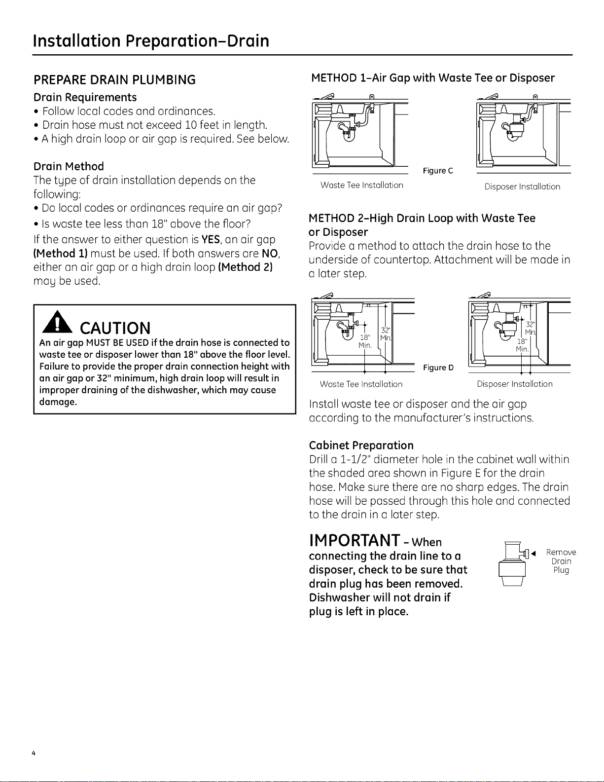
METHOD 1-Air Gap with Waste Tee or Disposer
Figure C
Waste Tee Installation
Disposer Installation
METHOD 2-High Drain Loop with Waste Tee
or Disposer
Provide a method to attach the drain hose to the
underside of countertop. Attachment will be made in
a later step.
Figure D
Waste Tee Installation
Install waste tee or disposer and the air gap
according to the manufacturer's instructions.
Disposer Installation
Cabinet Preparation
Drill a 1-1/2" diameter hole in the cabinet wall within
the shaded area shown in Figure Efor the drain
hose. IVlakesure there are no sharp edges. The drain
hose will be passed through this hole and connected
to the drain in a later step.
IMPORTANT- When
connecting the drain line to a
disposer, check to be sure that
drain plug has been removed.
Dishwasher will not drain if
plug is left in place.
41 Remove
Drain
Plug
Page 5

Installation Preparation-Electrical Supply
PREPARE ELECTRICAL WIRING
r!_LVAVl.'Ifl_11_[Cl
Electrical Requirements
• This appliance.must be s.upplied with 120V 60 Hz.,
and connected to an indiwduot properly grounded
branch circuit, protected by o 15 or 20 ampere
circuit breaker or time delay fuse.
• Wiring must be 2 wire with ground.
• If the electrical supply does not meet the above
requirements, coil o licensed electrician before
proceeolng.
TGhroundingInstructions-Permanent Connection
is qpplionce must be connected to o grounded
metal, permanent wiring sg.stem or on e.quipment
grou.nding cond.u,ctor must be. run.with the circuit
conduc.tors and be connected to the e.q.uipment
grounding terminal or lead on the appliance.
Grounding Instructions-Power Cord.Models _
This QppliQnce must be grounded. In the event ot Q
molfuoctioq or breqkdqwn, ground.ing will re.duce
.the risk at electric shock by providinq o path at
least resistgnce for electric current. This appliance
is equipped with o cord h_avingon equipment. .
grounding conductor and o grounding pl.ug..The plug
must be pluqged into on appropriate outlet that _s
installed onclqrounded in accordance with oll local
codes and orcTinonces.
FORPERSONALSAFETY:Remove house
fuse or open circuit breaker before
beginning installation. Do not use an
extension cord or adapter plug with this
appliance.
PARASEGURIDAD PERSONAL: Retire el fusible
de la casa o abra el interruptor de circuitos
antes de empezar la instalaci6n. No use un
cable de extensi6n o enchufe adaptador con
este aparato.
Figure E Black
Cabinet Preparation & Wire Routing
• The wiring mug enter the opening from either side,
rear, or floor within the shaded area illustrated
above in Figure E.
• Cut c] :£-:£/2" maximum diameter hole to insert the
electrical cable. Permanent wiring connections
mug puss through the same hole us the drain
hose and hot water line, if convenient. Hole edges
must be smooth and rounded. If the cabinet wall is
metal, the hole edge must be covered with c]cord
protector.
NOTE: Power cords with plug must puss through c]
separate hole.
Cord Hole Diameter
Protector 1-1/2" Maximum
/ \
/
..... l-i/2"_ia.
Receptacle from Wall
Location
Area
Ground J
24"
\.
3,_ Receptacle
from
'Cabinet
White
Alternate
Location
The improper connection of the equipment
grounding conductor can result in electric
shock. Check with a qualified electrician or
service representative if you are in doubt
that the appliance is properly grounded.
Do not modify the plug provided with the
appliance; if it will not fit the outlet, have
a proper outlet installed by a qualified
technician.
La conexi6n incorrecta del conductor de
conexi6n a tierra del equipo puede resultar en
choque el_ctrico. Consulte con un electricista
celificado o representente de servicio si tiene
dudes de la conexi6n e tierra del aperato. No
modifique el enchufe que se suministra con
el aperato; si no celze en el tomacorrientes,
hege queun t_cnico celificedo le instele un
tomacorrientes adecuedo.
Electrical Connection to Dishwasher
Electrical connection is on the right front of
dishwasher.
• For permanent connections, the cable must be
routed us shown in Figure E.The cable must extend
c] minimum of 2/4"from the rear wall.
• For power cord connections, install c_3-prong
grounding type receptacle in the adjacent cabinet
rear wall, between 6" and 18" from the opening, 6"
to 18" above the floor us shown in Figure E.
Page 6

Installation Preparation-Hot Water Supply
PREPARE HOT WATER SUPPLY
Hot Water Line
• The line may enter from either side, rear, or floor
within the shaded area shown in Figure F.
• The line mag pass through the same hole as the
electrical cable and drain hose, or cut an additional
1-1/2" diameter hole to accommodate the water
line. tf a power cord with plug is used, the water line
must not pass through the power cord hole.
/
Shut-off
ii
_Valvc
Hot_:::::
II
',',2"--
From
Cabinet
Cabinet Face-'-
19" From Wall
2" From Floor
The hot water supply line pressure must be at least 20 PSI.
Lower pressures could cause the water valve to leak and
cause water damage.
Sink Utility Connections
Sink faucet hot and cold water lines and the sink
drain line must run above and adjacent to the
dishwasher, not behind it. Refer to Areas A and C
in Figure A on page 3 and Figure F1 below. This is
necessarg to provide clearance for the dishwasher
when it is installed in the cabinet. Utilitg lines routed
directlg behind the dishwasher will interfere with
placement of the dishwasher in the cabinet and
cause it to extend begond the adjacent cabinets.
Figure F1 illustrates an installation using a double
bowl sink, a disposer and a high drain loop.
Note: All utilitg lines are above, below or adjacent to
the dishwasher. None are routed behind it.
CAUTION
Figure F
Water Line Connection
• Turn off the water supplg.
• Install a hand shut-off vatve in on accessible
location. (Optional, but strongtg recommended and
mag be required bg local codes.)
• The water connection is on the left side of the
dishwasher. Install the hot water inlet line, using
3/8" or larger copper tubing. Route the line as
shown in Figure F and extend forward at least 19"
from rear wall.
• Adjust the water heater to deliver water between
120°F and 150°F.
• Flush water line to clean out debris. Use a bucket
to catch water and debris.
• The hot water supplg line pressure must be
between 20 and 120 PSt.
6" Double-bowl
/ 25" deep
_,1-1/2" thick
i
__1 Countertop
_ _ elbow
-1-1/2" Close
acemaker ceS;II
_..'__.,_ir,,_'-- _ i
Coldwa "_ _;''
Valve to shut off Dishwasher
Hotwate__
water to dishwasher water inlet
Hot water supplg valve
to dishwasher Dishwasher
Figure FI
drain hose
Page 7

Dishwasher Installation
CAUTION
Do not remove the wood bose until you ere reedy
to instell the dishwesher. The dishwasher will tip over
when the door is opened if the bose is removed.
STEP 3: REMOVE WOOD BASE
IMPORTANT - Donot kick off wood base!
Damage will occur.
Hove the dishwasher close to the installation
STEP 1: PREPARATION
Locatethe itemsintheinstallationpackage and set
them asideforuse inthe listedsteps
• Screw kit-Steps5 or 16 and 13
• Junctionboxcover-Steps5 or 16
• Drain hose and drain hose clamp-Step 7
• Owners' Manual-Steps 18 and 21
• Product Samples and/or coupons-Step 21
STEP 2: CHECK DOOR BALANCE
• With the dishwasher on the wood base, check the
door balance by opening and closing the door.
• The door is properly balanced if it gently drops
from a 1/2 open position and does not rise from
the full open position.
• If necessary, increase or decrease tension as
shown. Latch the door and adjust springs to
correct balance.
Link fullg seated
in hinge arm
Insert Hook Throuc
Hole from Inside of Frame
Figure G
Tip: Avoid service calls for door balance problems
Hake sure the spring end is fully engaged in a
frame hole and the spring link is fully seated in the
hinge arm.
Remove the four leveling
legs from the underside of
Iocationandlayitonitsback_i _D
the wood base
with a 15/16" _--
i
socket wrench.
Remove and
discord wood
base.
Figure H
• Screw leveling legs back into the dishwasher
frame, approximately 3/4" from the frame, as
shown.
STEP 4: REMOVE ACCESS PANEL
AND TOEKICK
The top mounting holes in the access panel are
slotted.
• Remove the lower two 10-16x3/8" sheet metal
screws. Do not remove the two top 8-32xl/4"
machine thread screws.
• Slide the access panel to the left as far as it will go.
• Gently pull the access panel forward to remove
it from the top screws.
Set access panel, toekick, and screws aside for use
in Step 20.
Tip: Prevent
tub damage
Remove onlg
the 3/8" sheet
metal screws
in this step.
This will help
prevent a mix
up with the
1/4" machine
thread screws
in Step 20.
Do not remove 1/4"
machine thread screws
in this step
,.J
Remove two
3/8" Sheet Metal
Thread Screws
Figure I
Page 8

Dishwasher Installation
STEP 5: INSTALL POWER CORD
Skip this step if the dishwasher will be
permanently connected to the house electrical
system or has a factory installed power cord.
In this step you will need the junction box cover and
the #:1_0x :1_/2"hex head screw from the screw kit set
aside in Step 1.
The power cord and connections must complg
with the National Electrical Code, Section/422 and/
or local codes and ordinances. Maximum power
cord length is 6 feet. Power Cord Kit WX09X70910,
available for purchase from an authorized GE
Appliance Dealer, meets these requirements.
STEP 6: INSTALL 90° ELBOW
• Wrap a 90 ° elbow with thread seal tape.
• Thead the 90° elbow into the water valve.
• Do not over tighten the elbow; water valve bracket
could bend or the valve fitting could break.
• Position the end of the elbow to face the rear of
the dishwasher.
Bracket
RedElectrical
90°
Figure K
STEP 7: INSTALL DRAIN HOSE TO
DISHWASHER DRAIN PORT
Thread Seal Connection
Tape Hose
Junction
Box Bracket
Ilack
Figure J
• Install strain relief in thejunction box bracket.
• Insert the power cord through the strain relief and
tighten.
• Make sure black, white, and green dishwasher
wires are threaded through the small hole in the
junction box bracket.
• Connect power cord white (or ribbed)to
dishwasher white, black (or smooth) to dishwasher
black and ground to dishwasher green wire. Use
UL listed wire nuts of appropriate size.
• Install junction box cover using the #10 hex head
screw. Be sure wires are not pinched under the
cover
8
Skip this step if drain hose has been pre-installed.
In this step you will need the drain hose and clamp
set aside in Step 1.
IMPORTANT- Prevent drain hose damage
and possible leaks. Be careful not to nick or cut
the drain hose.
• Route the small end of the drain hose from the left
side of the dishwasher through the strain relief
attached to the dishwasher frame and toward
the center of the dishwasher as shown in Figures
Land M.
• Place the hose clamp over the small end of the
drain hose.
• Push the small end of the drain hose over the drain
port on the collection chamber making sure it is
futlg seated against the hose stop.
• Tighten the hose clamp to at least 15 inch-pounds
of torque.
\\. / ,Strain
Figure L
Page 9

Dishwasher Installation
Note: The droin hose supplied with the dishwosher
is opproximotelg 78" long. tf o longer hose is needed,
o ZOfoot long hose mog be purchosed from on
outhorized GE opplionce deolen The 10 foot long
hose is port number GPFIOS.
Hose Stop
DrQin Hose Collection Chomber
Figure M
Do not use
this port if
present
DrQin Port
STEP 9: INSERT DRAIN HOSE AND POWER
CORD, IF USED, THROUGH CABINET
• Upright the dishwosher and position it in front of
the cobinet opening.
• Insert the droin hose into the hole previously drilled
in the cobinet woll.
• If o power cord is used, guide the end of the cord
through o seporote hole cut for the power cord.
The power cord should be routed directly to the reor
of the junction box ovoiding contoct with the door
spring ond other dishwosher components.
Figure O
Tip: Avoid unnecessary service charges for drain
issues
Moke sure the droin hose connection is leok free
ond the hose is routed through the stroin relief so
it will not kink when the dishwosher is instolled into
the cobinet.
STEP 8: POSITION WATER LINE AND
POWER SUPPLY
• Position the woter supply line ond house wiring on
the floor of the opening to ovoid interference with
the bose of dishwosher ond components under
the dishwosher.
Line Supplg
Tip: Avoid unnecessary service charges for no fill,
drain, or noise concerns
Position utilitg lines so theg do not interfere with
ongthing under or behind the dishwosher.
STEP 10: INSTALL OPTIONAL GPF65 SIDE
MOUNT BRACKETS
Skip this step if the underside of countertop is
wood or wood like material.
• Purchose ond instoll the GPF65 side mount brocket
kit if the underside of counter is gronite or o
similor moteriol thot will not occept wood screws.
The GPF65 kit is ovoiloble from outhorized GE
opplionce deolers.
• Refer to Figure P ond follow the instructions
included in Side-
the kit.
Tub Frome
Figure N
Brocket
Attochment
__ Optional Screws
Side-Mount (2 Eoch
Bracket Kit Figure P Side)
Page 10

Dishwasher Installation
STEP 11: SLIDE DISHWASHER INTO CABINET
IMPORTANT - Do not push against the front
panel with knees. Damage will occur.
• Grasp the sides of the front panel and slide the
dishwasher into the opening a few inches at
a time. Pull the drain hose and power cord, if
equipped, through the holes in the adjacent
cabinet while sliding the dishwasher into position.
Do not ush a ainst
front door panel with
Figure _)
knee. Damage to the
door panel will occur.
STEP 12: POSITION AND LEVEL
DISHWASHER
IMPORTANT- Dishwasher must be level for
proper dish rack operation, wash performance,
and door operation. The dishwasher must be
leveled left to right and front to back. This assures
that the dish racks will not roll in or out on their
own, circulation water will flow to the pump inlet,
and the door will close without hitting the side of
the tub.
• Remove the lower dish rack and place a level on
the door and lower rack track as shown in Figure R.
/
Check Level
Front-to-Back
• Check the tub insulation blanket, if equipped, to
be sure it is smoothly wrapped around the tub.
It should not be "bunched up" and it must not
interfere with the door springs. If the insulation
is "bunched up" or interfering with the springs,
straighten and re-center the blanket prior to sliding
the dishwasher into its final position.
• IVlake sure the drain hose is not kinked under or
behind the dishwasher.
• IVlake certain the house wiring, drain line, and
water line do not interfere with components under
the dishwasher.
• The dishwasher tub flange should be
approximately 3/4" behind the face of the adjacent
cabinet. Refer to Figure R.
Tip: Avoid unnecessary service charges for panel
damage.
Do not press on the center of panel with hands or
knees when sliding dishwasher into position.
lo
Figure R
qeck Level
Side-to-Side
• Adjust the level of the dishwasher by individually
turning the four legs on the bottom of the
dishwasher as illustrated in Figure S.
I J
\,, i
!- .S
Turn Lec J
to AdJust J FigureS
• The dishwasher is properly leveled when the level
indicator is centered left to right and front to back.
The dishwasher door should close without hitting
the sides of the tub.
• Replace the lower rack.
Tip: Avoid unnecessary service charges for poor
wash performance and rack operation.
Pull the dish racks halfway out. They should remain
stationary. Open and close the door. The door should
fit in the tub opening without hitting the side of the
tub. If the racks roll on their own, or the door hits the
side of the tub, re-level the dishwasher.
Page 11

Dishwasher Installation
STEP 13: FASTEN DISHWASHER TO
UNDERSIDE OF COUNTERTOP OR SIDES
OF CABINET
In this step you will need the two 5/8" Phillips head
wood screws set aside in Step 2.
IMPORTANT - Dishwasher must be centered
in cabinet opening. Interference with cabinets or
countertop will cause leaks and damage to the
door panel and/or control panel.
• If countertop is wood or woodlike material, fasten
the dishwasher to the countertop bg driving the
Phillips head screws through the countertop
brackets and into the countertop.
• If the countertop is granite or similar material,
drive Phillips screws through side mount brackets
and into the adjacent cabinets.
• Make sure screws are driven straight and flush
to prevent interference with door operation and
damage to the control panel. See Figure T.
STEP 14: CONNECT WATER SUPPLY
Connect the water supplg line to the 90° elbow
installed in Step 6.
• Slide the compression nut and then the ferrule over
end of the water line.
• Insert the water line into the 90° elbow.
• Slide the ferrule against the elbow and secure
with the compression nut.
Countertop
Bracket
Side Mount
Brackets (optional)
Figure T
Tip: Avoid unnecessary service charges for leaks
or control panel damage.
Make sure the dishwasher is centered in the cabinet
and the door opens and closes freelg without hitting
the adjacent cabinets. Drive mounting screws
straight and flush.
Figure U
IMPORTANT - Check to be sure the door
spring does not rub or contact the fill hose or
water supply line. Test by opening and closing the
door. Re-route the water supply lines or slightly
bend the water valve bracket if a rubbing noise or
i nterference occurs.
Tip: Avoid unnecessary service charges for noise
or leaks
Make sure the door spring does not rub against the
fill hose or water supplg line.
11
Page 12

Dishwasher Installation
STEP 15: CONNECT DRAIN LINE
The molded end of the drain hose will fit 5/8"
through 1" diameter inlet ports on the air gap, waste
tee or disposer.
• Determine the size of the inlet port
• Cut the drain hose connector on the marked line, if
required, to fit the inlet port.
Cutting Line
,/
/.
Figure V
• If a longer drain hose is required, and Uou did not
purchase the GPF10S drain hose, add up to 42"
length, for a total of 120" (10 feet) to the factory
installed hose. Use 5/8" or 7/8" inside diameter
hose and a coupler to connect
the two hose ends.
Secure the
connection
with hose
clamps.
IMPORTANT - Total drain hose length must
not exceed 10 feet for proper drain operation.
IMPORTANT: Do not cut corrugated
portion of hose
Hose Clamic
Coupler
Hose Clamp
Figure W
Method 1 - Air gap with waste tee or disposer
_.i___ _ _/-___
Waste Tee Installation Disposer Installation
Figure ×
Method 2 - "High drain loop" with waste tee or
disposer
Fasten the drain hose to the underside of the
countertop with a hanger.
32"
Waste TeeInstallation
Figure Y
Disposer Installation
IMPORTANT - When connecting the drain
line to a disposer, check to be sure that the drain
plug has been removed. Dishwasher will not drain
if plug is left in place.
• Connect drain line to air gap, waste tee, or disposer
using the previouslg determined method. Secure
the hose with a screw tgpe clamp.
12
Drain
Plug
4 Remove
Tip: Avoid unnecessary service call charges
for a no drain complaint
Make sure any excess drain hose has been pulled
through the cabinet opening. This will prevent
excess hose in the dishwasher cavity from
becoming kinked or crushed by the dishwasher.
Make sure the disposer plug has been removed if
the drain hose is connected to a disposer.
Page 13

Dishwasher Installation
STEP 16: CONNECT POWER SUPPLY
If a power cord with plug is already installed,
proceed to Step 17.
If house wiring is not 2-wire with a ground
wire, a ground must be provided by the
installer.
When house wiring is aluminum, be sure to
use U.L. listed anti-oxidant compound and
aluminum-to-copper connectors.
Si el cableado de la casa no es de 2 cables
con un cable de conexi6n a tierra, el
instalador debe suministrar una conexi6n
a tierra. Cuando el cableado de la casa es en
aluminio, cerci6rese de usar un compuesto
ti-oxidante aprobado por U.L.
yun compuesto de aluminio a cobre.
• Secure house wiring to the bock of the junction
box brocket with o stroin relief.
• Locote the three dishwosher wires, (white, block
ond green) with stripped ends. Insert dishwosher
wires through the smotl hole in the junction box
brocket. Use UL listed wire nuts of oppropriote size
to connect incoming ground to green, white to
white ond block to block.
Note: Check thot horness leods ore
threoded through smoll hole in brocket
White
Junction Ground
Box Brocket
\
Figure Z
STEP 17: INSTALL JUNCTION BOX COVER
If junction box cover is already installed, skip to
Step 18.
In this step you will need the junction box cover ond
the #10 hex heod screw from the screw kit set oside
in Step 1.
• Instotl the junction box cover using the #10 hex
heod screw. Check to be sure thot wires ore not
pinched under the cover.
STEP 18: PRE-TEST CHECK LIST
[] Verify thut power is turned off ut the source.
[] Open the dishwasher door and remove all foum
und cordbourd puckuging.
[] Reod the Owner's Munuul to fumiliurize yourself
with the operution of the dishwusher.
[] Check to be sure thut the wiring is secure
under the dishwusher, und not pinched or in
contuct with door springs or other dishwusher
components.
[] Check thut the door spring does not contuct the
wuter line, fill hose, or udjucent cubinets. See
Steps 13 ond :]_4
[] Pull lower rock obout holfwoy out. Check to be
sure it does not roll bock into dishwosher or
further out. tf it does, re-level the dishwosher.
See Step :]_2
[] Check to be sure control ponel does not touch
odjocent cobinets. If it does, reposition the
dishwosher. See Step 13
[] Turn on the hot woter foucet ot the sink to verify
thot the woter temperoture is ot leost :]_20°F
ond not more thon :]_S0°F.Adjust woter heoter
if necessory.
[] Add two quorts of woter to the bottom of the
dishwosher to lubricote the pump seol.
[] Turn on woter supply.
[] Check for woter leoks. Tighten connections if
necessory. See Step :]_4
[] Remove the protective film if present from the
control ponel, occess ponel ond door ponel.
13
Page 14

Dishwasher Installation
STEP 19: DISHWASHER WET TEST
CHECK LIST
[] Turn on power supply or if power cord is used,
plug it into the wall outlet.
[] Latch dishwasher door.
[] Press the "Normal" pad, and then turn control dial
just enough to start dishwasher. Be careful not to
turn the dial past the first water fill. Dial should
point to "Hot Start Option".
Options
Appearance varies by model.
[] Check to be sure that water enters the dish-
washer. This could take up to 4 minutes.
If water does not enter the dishwasher try the
following to correct the problem:
- Check to be sure that the water is turned on
- Lightly tap the flood float cover to
dislodge a stuck flood float.
Q
Cover
- Check the electrical connection to the water
valve. The red electrical connector should be
plugged into the dishwasher water valve. If it is
not plugged in, turn off electrical power to the
dishwasher. Plug the red connector into the dish-
washer water valve and then restore power.
Red Connector
[] Check for leaks under the dishwasher. If a leak is
found, turn off power, tighten connections and
restore power.
[] Check for leaks around the door. A leak around
the door could be caused by the dishwasher door
rubbing or hitting adjacent cabinets. Reposition
the dishwasher if necessary. See Steps :1_:1_,12
and 13.
[] Most dishwasher models will drain about 3 min-
utes after the first fill. Check the drain line for
leaks when dishwasher drains. If leaks ore found,
turn off power, correct as necessary and then
restore power.
[] Open the dishwasher door and make sure most
of the water has drained. If the water does not
drain, check to be sure disposer plug has been
removed and/or air gap is free of debris.
[] Let the dishwasher run through another fill and
drain cycle. Check again to be sure there ore no
leaks.
[] At the end of the second drain, unlatch the door
and rotate the dial to the "OFF" position.
14
Page 15

Dishwasher Installation
STEP 20: REPLACE ACCESS PANEL AND
TOEKICK
In this step you will need the panels and the two
screws set aside in Step 4.
There are two tgpes of screws used. The 8-32 x 1/4"
screws are used at the top of the access panel and
should still be in place. The 20-16 x 3/8" screws are
used at the bottom of the access panel and secure
both the access panel and toekick.
IMPORTANT - screws are not
interchangeable. To prevent damage to your
dishwasher, use the proper screw in the proper
location. Do not mix screw types or lengths.
• Place the toekick against the legs of the
dishwasher.
• Remove the two 8-32 x 1/4" machine thread
screws.
• Align the access panel to the dishwasher.
• Select the two 8-32 x 1//4" machine thread screws
just removed and insert them through the top
holes in the access panel and into the dishwasher
frame.
• Tighten these screws.
• Align the toekick and make sure the bottom edge
is against the floor.
• Insert and tighten the two 10-16 x 3/8" sheet metal
thread screws, making sure the bottom edge of
the toekick stags in contact with the floor.
STEP 21: LITERATURE
[] Leave the Owners' Manual, Installation
Instructions, samples, and/or coupons with
consumer.
Remove, then Reinstoll ond Tighten
Instoll ond Tighten ....
10-16 x 5/8"
Sheet Metol Threod Screws
8-52 x 1//4"
Mochine Threod Screws
Figure AA
Tip: Prevent tub damage and reduce sound from
under the dishwasher
Use the machine thread screws in the top holes and
the sheet metal thread screws in the bottom holes.
Make sure the toekick is against the floor.
15
Page 16

SPECIFICATIONS SUBJECT TO CHANGE WITHOUT NOTICE
GEConsumer & Industrial
General Electric Compang
Louisville, Kentuckg 40225
GEAppliances.com
16
Pub.No. 31-30271
Dwg. No. 206C1559P177
ND 06M-2101 (1/07)
Page 17

_iiii:iiiii¸!i!!!!ii!i!iCo i'_:!!!ii;i,.iiii-_"__!!!:?i'¸¸¸¸¸i!!!iiiiiii_iH_i-i_:i::il,.ii!!!!ii;:iii:ii:io!ii
Appliances
Notice d'installation
Lave-vaisselle Spacemaker ®
En cas de questions, appeler le 800.GE.CARES (800.432.2737) ou rendre visite _ notre
site web : www.GEAppliances.com
AVANT DE COMMENCER
Lire cette notice d'installation en entier
et avec soin.
IMPORTANT - Respecter tous les codes et
r_glements en vigueur.
• Remarque 0 I'intention de I'installateur : Laisser
cette notice pour le client et I'inspecteur local.
• Remarque _ I'intention du consommateur :
Ranger cette notice avec le Guide d'utilisation pour
consultation utt6rieure.
• Niveau de comp6tence : L'installation de ce lave-
vaisselle requiert des comp6tences m6caniques,
61ectriques et de plomberie 616mentaires.
L'installateur est responsable de I'installation
correcte. La garantie des appareils m6nagers GE
ne couvre pas une d6faillance de produit caus6e
par une installation incorrecte. Se reporter au×
informations dans la garantie.
• Dur6e d'installation : De 1 _ :3 heures.
L'instatlation initiale requiert plus de temps que
I'installation d'un appareil de remplacement.
• Caract6ristiques n6cessaires de 1'6vier : Le lave-
vaisselle Spacemaker ® est conqu pour 6tre instatl6
sous un 6vier sp6ciat peu profond. Ce tgpe d'6vier
est offert en trios mod61es diff6rents : le GPF95, un
6vier simple avec le trou de vidange au c6t6 droit
de 1'6vier ; le GPF96, un 6vier simple avec le trou
de vidange au c6t6 gauche de 1'6vier ; le GPF97,
un double 6vier. Ces 6viers sont en vente chez les
distributeurs agr66s d'appareils m6nagers GE.
IMPORTANT - Le lave-vaisselle DOlT atre
install_ de mani_re 6 permettre la d_pose
ult_rieure de I'enceinte pour route intervention
ult_rieure.
Prendre imm_diatement contact avec le
distributeur ou I'entrepreneur de construction si le
lave-vaisselle livr_ est endommag_.
Accessoires en option - Consulter la liste de
panneaux sur mesure dans le Manuel de I'utilisateur.
SI_CURITI_
Lire et observer tousles avertissements
(PRUDENCE et ATTENTION) de cette notice.
Toujours porter des gants et des lunettes de
s_curit_ en ex_cutant les procedures d'installation
d_crites dans la notice.
LIRE ATTENTIVEMENT.
IL FAUT GARDER CES INSTRUCTIONS.
Page 18

PII_CESFOURNIES DANS LE
N#CESSAIRE D'INSTALLATION
[] Deux (2)vis 5 bois 5 t@tecruciforme n°
8-18 de 5/8 po
[] Un couvercle de boTtedejonction et une
vis h t@te h six puns n° 10
[] Tuguu de vidunge de 198 cm (78 po) et
collier de tuguu
[] Documentation, _chuntillons et/ou
coupons de r_duction
MATE_RIAUX REQUIS
[] Cordon _lectrique WXO9X70910 si requis
pour I'instullution
[] Trois (3) serre-fils homologu_s UL
[] Rubun d'_tanch_it_ pour joints filet_s
[] Coude h angle droit, bugue et _crou de
compression (filetuge externe de 3/8
po h une extremitY, I'uutre extr_mit_
_tunt dimensionn_e pour s'udupter h
I'utimentution en euu)
[] Kit de support h montage lateral GPF65
pour les plans de travail en granite
POUR LES NOUVELLES INSTALLATIONS
[] Chble _lectrique
[] Conduite d'eau en cuivre de MINIMUM
3/8 po
[] R_ducteur de tension pour branchement
_lectrique
[] Robinet d'arr_t manuel (recommand_)
[] Intervatle d'air pour le tuyau de vidange,
si n_cessoire
[] T_ de vidage pour la plomberie de la
maison, si n_cessaire
[] Colliers de tuyau 8 vis
[] Evier GPF95, GPF96 ou GPH97 en acier
inoxydable
Ensemble de vis
_Visaboisat6te =[_ VispourboTtede
Tuyau de vidange tuyau
de 198 cm 178po}
C6ble _lectrique ou
cordon d'alimentation
WR09×70910
Coude 6 angle droit,
bague et _crou de
compression
cruciforme n ° _ jonction 6 t6te 6
8 de 518 po de _ six pans n°
long "_ 10- 112 po de long
Collier de
3 serre-fils
Kit de support 6
montage lat6ral
GPF65
O
R_ducteur de
tension
I_vier GPF95 en acier
inoxydable
Robinet
d'arr_t
Intervalle T_ de
d'air vidage
I_vier GPF96 en acier
inoxydable
Couvercle de boTte
de jonction
d'_tanch_it_
de filet
Conduite d'eau en
cuivre de 318 po
minimum
Colliers de tuyau
6 vis
I_vier GPF97 en acier
inoxydable
OUTILS REOUIS
[] Lunettes de s_curit6
[] Tournevis h douille de 1//4 po et 5/16 po
[] Lampe de poche
[] Gants
[] CI6 5 molette de 15 cm (6 po)
[] Tournevis _]t6te cruciforme
[] Cl_ 8 douille de 15/16 po
[] IVt6treruban
[] Niveau
[] Equerre de menuisier
[] Seau pour attraper I'eau vidang6e
du tugau
[] Coupe-tube
POUR LES NOUVELLES INSTALLATIONS
[] Scie cloche
[] Perceuse et m_ches appropri_es
Lunettes de s6curit_
Gants
M_tre ruban
Bucket
Tournevis 6 douille de 114 po
et de 5/16 po
Cl_ 6 molette Tournevis
Niveau
Coupe-tube
cruciforme
Scie cloche
Lampe de poche
21_6 douille de
15/16 po
I_querre de
menuisier
Perceuse
et m6ches
appropri_es
Page 19

Preparation pour I'installation - Enceinte
PRI:!PARATIONDE L'ENCEINTE DU LAVE-
VAISSELLE ET DE L'EMPLACEMENT DE L'I:!VIER
• Installer les tugaux d'alimentation d'eau et de
vidange de 1'6vier dons la section A.
• Installer le tugau d'eau chaude vers le lave-
vaisselle dons la section B.
• Installer le brogeur de d6chets, les tugaux
d'alimentation d'eau du robinet, le siphon,
I'intervalle d'air et le robinet d'arr@ de I'eau dons
une armoire large de 30 cm (12 po), la section C.
Plan de travail: 6paisseur min. de 3,8 cm (1 1/2 po)_
Max. 26 cm
(i0 1/4 io)
II
Plinth
/
• Le diam_tre de I'ouverture du brogeur de d_chets
duns I'_vier doit @re de 19 cm (7 1/2 po), comme
indiqu6 8 lu section C.Ceci permet d'instutler le
brogeur et Io plomberie duns Io section C uvec un
_vier soit simple, soit double. Se reporter 8 Io figure
A ci-dessous et 5 Io figure F1 5 Io page 6.
Max. 52 cm
--cuve de
Min. 1,9 cm (3/4 po)--[ I_ _in. 28 cm
[
3 cm (1
de 3,8 cm 2'
(i1/2 po)
du coude
Max. 15 cm
rue lat6rale
du lave-vaisselle
Max.i0cm
(4 po)
(20 1/2 po)
(6 po)
D6g. max.
cm (11 3/4 po)
plomberie
_/jvlur
Max. 2,5 cm (ipo)
PROFONDEUR MAX
DE 26 cm (lO 1/4 po)
POUR PLOMBERIE
de 1'6vier
t
I.... I._ _J',,
Min. 30 cm So
61 cm (24 po 112po)
PRI:!PARATION DE L'ARMOIRE POUR
L'INSTALLATION DE L'I_VIER
r!_.,'lli=_ll[e]_l
• L'ouverture de I'armoire doit ovoir one largeur et
une profondeur d'au mains 61 cm (24 po) et une
hauteur de 87 cm + 0.6 cm (34 1/4 po + 1/4 po).
• Ce lave-vaisselle s'encastre sous un @viersp@ciat
d'une profondeur de maximum 15 cm (6 po) dans
un plan de travail de 3,8 cm ( 1 1/2 po).
_D6coupe
Pour r_duire le risque de choc _lectrique,
d'incendie ou de blessures, I'installateur
doit s'assurer que le lave-vaisselle est
enti_rement enclos au moment de
I'installation.
pour 1'6vier
20 cm x 51 cm
(8 x 20 po) d6coupe
arri@e de I'armoire
adjacente
Min. 61 cm
Figure A
(24 po) armoire
• Le lave-vaisselle doit @re enti_rement enclos sur le
hout, les c6t_s et I'orri_re.
• Le Iove-voisselle ne peut toucher oucune portie de
I'enceinte.
Mur
/
--Max. s2cm ----
20 1/2 po cuve_d'#vier
avant _,
du bac
Espace
\
Remarque. - II peut y avoir un espace entre le rebord avant du
Lave-vaisselle
_------Min.61 cm--
(24 po)armoire
bac du lave-vaisselle et I'avant de I'armoire sila
profondeur de I'armoire est mains de 61 cm (24
po) ou sila cure d'6vier n'a pas 6t6 install6e selon
les directives.
Figure B
adjacent au lave-vaisselle
cm (24 po)
Si I'espacement est de plus de 2 cm (314po),
il faut d6placer la cuve d'6vier pour qu'elle
s'accorde aux dimensions indiqu6es.
Page 20

Preparation pour I'installation - Vidange
PRI_PARATION DE LA PLOMBERIE
DE VIDANGE
Exigences de vidange
• Respecter les codes et r_gtements Iocaux.
• Le tuyau de vidange ne peut pas @re plus de 3 m
(10 pi)de long.
• Une boucle de vidange #lev#e ou un intervalle d'air
est requis. Voir ci-dessous.
M_thode de vidange
Letype d'installation de vidange est li@aux
conditions suivantes :
• Est-ce que les codes ou r@gtements Iocaux exigent
un intervalle d'air ?
• Est-ce que le t6 de vidoge se trouve 5 mains de 46
cm (18 po)du sol ?
Si la r@ponse _ une de ces questions est OUI, il
faut utiliser un intervalle d'air (m@thode n° 1). Si Io
r6ponse est NON oux deux questions, il fout utiliser
soit un intervolle d'oir, salt une boucle de vidonge
61ev6e (m_thode 2).
PRUDENCE
II FAUTutiliser un intervalle d'air si le raccord du tuyau
de vidange au t_ de vidage ou au broyeur de d_chets
est 6 mains de 46 cm (18 po) du niveau du sol. Le lave-
vaisselle risque de ne pas se vidanger correctement et
de s'endommager si le raccord de vidange n'est pas 6 la
bonne hauteur avec un intervalle d'air ou une boucle de
vidange _lev_e de minimum 81 cm (32 po).
MISTHODE 1 - Intervalle d'air avec t@de vidage ou
broyeur de d@chets
Figure C
Installation avec t6
devidage
MI_THODE 2 - Boucle de vidange @lev@eavec t@de
vidage ou broyeur de d@chets
Trouver un moyen d'attacher le tuyau de vidange
au-dessous du plan de travail. Ceci sera accompli 5
une @ape utt@rieure.
Installation avec brogeur
de d@chets
v46 m,To,
Figure D
Installation avec t6
de vidage
Installer le t@de vidage ou le broyeur et I'intervalle
d'air selon les directives du fabricant.
Pr@paration de I'armoire
Percer un trou de 38 mm (Z Z/2 po) dans la paroi de
I'armoire dons la zone hachur@e indiqu@e 5 la figure
E pour le passage du tuyou de vidonge. V@rifier
que les bards du trou sont lisses. Dons une @ape
ult@rieure, il lout gtisser le tuyau de vidange ou
travers du trou pour le raccorder au drain.
Installation avec brogeur
de d@chets
IMPORTANT- Pendant le
raccord du tuyau de vidange
au broyeur de d_chets, v_rifier
que le bouchon de vidange a
_t_ enlev_. Le lave-vaisselle
ne peut pas se vider avec le
bouchon en place.
bouchon
de vidange
, nlever le
Page 21

Preparation pour I'installation - alimentation lectrique
PRI_PARATION POUR LE BRANCHEMENT
I_LECTRIOUE
v!Y-'_ll_l_ll[e]_l
Alimentation _lectrique
• Cet appareil dolt avoir une alimentation @lectrique
de 120 V,60 Hz et @re branch_ sur un circuit
ind6pendant correctement mis 5 la terre et
prot6g6 par un disjoncteur de 15 ou 20 A ou un
fusible temporis6.
• Le cOblage dolt @re 5 deux ills plus un fit de mise
terre.
• Si I'alimentation 6lectrique n'est pas conforme
ces conditions, appeler un 6lectricien agr66 avant
de continuer.
Mise 6 la terre - raccord permanent
Cet appareil dolt @re raccord@ de faqon permanente
un r@seaude ills m@alliques mis 5 terre ou il
faut installer un fil de mise 5 terre avec les ills
d'atimentation. Cefil dolt @trebranch@ 5 la borne de
terre de I'@quipement ou 5 un fil sur I'appareil.
Instructions de mise 6 la terre - modules 6 cordon
d°alimentation
Cet appareil dolt @tremis 5 la terre. En cas de
mauvais fonctionnement ou de panne, la mise
la terre r@duit le risque de choc @lectrique en
fournissant un passage de moindre r@sistance au
courant @lectrique. L'appareil est @quip@d'un cordon
conducteur de mise 5 la terre et une fiche de terre.
IIfaut brancher la fiche sur une prise appropri@e qui
a _t@install_e et mise 5 la terre conform_ment aux
codes et r_gtements Iocaux.
SI_CURITI_: Enlever les fusibles ou
d_brancher le disjoncteur de la maison
avant de commencer I'installation. Ne pas
utiliser une rallonge ou un adaptateur de
prise avec cet appareil.
Un branchement incorrect du conducteur
de mise 6 la terre peut causer des chocs
_lectriques. En cas de doute sur la mise 6 la
terre de I'appareil, consulter un _lectricien
agr_ ou un r_parateur. Ne pas modifier
la fiche fournie avec I'appareil. Si la fiche
ne correspond pas 6 la prise, faire installer
une prise appropri_e par un _lectricien
qualifi_.
_ __ _ _
..S \.. Autre
" [ J ]'l emplacement
cm, , Troudemax.S8mm JJ / possible de
-Pm-_--/(1-1/2 po)dediam_tre lOcm _ la prise
46 cm _ , _ _\\Ocm(apo)4-U-_/ _ tt
18po, I_'{ ............! L__ LellI
\ I 1_-15cm B _ 7,5 cm (5 po)
\-M'-(6 po) (6po) m deI'armoire
\ _/- ....... o;
_t J \/ b J_cm\\ \1 I t
_ j/l] /Emplacement du mur XX,kX
_: -V dd: Icao:rr_et Terre__kL
Figure E Noir-_Bl!nc
Preparation de I'armoire et du passage des ills
• Les ills doivent entrer dans la cavit@ d'un c6t@
ou de I'autre, de I'arri@re ou du sol dans la zone
hachur@e indiqu@e 5 la figure E.
• Couper un trou d'un diam@tre maximal de
3,8 cm (1 1/2 po) pour permettre le passage
des fits d'alimentation @lectrique. Le c6ble de
branchement direct peut passer dans le m@me
trou que le tugau de vidange et le tugau d'eau
chaude si c'est plus pratique. Les rebords du
trou doivent @trelisses et arrondis. Si la paroi de
I'armoire est en m@al, recouvrir les rebords du trou
pour prot@ger les ills.
REMARQUE.- Un cordon d'atimentation muni
d'une fiche dolt passer par un trou s@par@.
Prot@
Branchement _lectrique du lave-vaisselle
Le branchement _lectrique se fait 5 I'avant droit du
lave-vaisselle.
• Pour les branchements permanents, acheminer
le c6ble tel indiqu@ 5 la figure E.Le c6ble dolt
s'@endre au moins 61 cm (24 po)de la paroi arri@re.
• En cas de branchement avec un cordon
d'alimentation, installer une prise 5 trois broches
sur la paroi arri@re de I'armoire adjacente de 15 cm
46 cm (6 po 5 18 po) de I'ouverture et de 15 cm
46 cm (6 po 5 18 po) au-dessus du sol, tel illustr@
la figure E.
_I" 1--12,5 cm (Spo) 1 jr(aPO)_J decourant
II \\\+-xl
Trou d'un diam@tre
maximal de
58 mm (i-i/2po)
Page 22

Preparation pour I'installation - Alimentation d'eau chaude
PRI_PARATION DE L'ALIMENTATION D'EAU
CHAUDE
Tuyau d'eou chaude
• Le tuyau peut entrer d'un c6t_ ou de I'autre, de
I'arri_re ou du sol dans la zone hachur_e indiqu_e
la figure F.
• Le tuyau peut passer par le m_me trou que le
cable _lectrique et le tuyau de vidange. Une
alternative est de couper un trou s_par_ d'un
diam_tre de 3,8 cm (1 1/2 po) pour accommoder
le tuyau d'eau. Le tuyau d'eau ne peut pas passer
par le trou du cordon d'alimentation si ce cordon
est muni d'une fiche.
cm (5 po)-
lO cm (4
Lo pression de Io conduite d'olimentotion d'eou choude
doit 6tre d'ou moins 1,4 bor (20 psi). Une pression plus
foible risque de couser une fuite dons le robinet et des
d_g6ts causes par I'eou.
Bronchement des conduites de I'_vier
Les conduites d'eau chaude et froide de I'@vier et
le tuyau de vidange de I'@vier doivent @tre instatl@s
au-dessus et _ c6t@ du lave-vaisselle et non derri@re
le lave-vaisselle. Se reporter aux zones A et C de
la figure A _ la page 3 et _ la figure F3_ci-dessous.
Ceci est n@cessaire pour laisser suffisamment de
d@gagement au lave-vaisselle au cours de son
installation dans I'armoire. Les conduites install@es
directement derri@re le lave-vaisselle risquent
d'entraver le placement du lave-vaisselle dans
I'armoire et de le pousser au-del@ des armoires
adjacentes.
PRUDENCE
h
Chaudll:-::-
cm
5 cm (2 po)
de I'armoire
Devant --.-
de I'armoire
Figure F
48 cm (19 po) du mur _l
5 cm (2 po) du sol
(6 po)
Bronchement du tuyou d'eou
• Couper I'atimentation d'eau.
• Installer un robinet d'arr@ manuel duns un
endroit accessible. (En option, mais fortement
recommand_ et peut @re exig_ par les codes
Iocaux.)
• La conduite d'eau se branche au c6t@gauche du
lave-vaisselle. Installer la conduite d'alimentation
d'eau chaude avec un tuyau en cuivre de
minimum 9 mm (3/8 po). Acheminer la conduite tel
illustr@ @la figure Fet I'amener _ un minimum de
48 cm (3_9po) du mur arri@re.
• R@gterle chauffe-eau pour que I'eau sorte _ une
temp@rature de 49 5 65 °C (3_205 3_50°F).
• Purger la conduite d'eau pour @liminer tous les
d@bris.Laisser couter I'eau et les d@bris dans un
seau.
• Lapression de la conduite d'alimentation d'eau
chaude dolt @treentre 3_,4et 8.3 bar (20et 3_20psi).
La figure F3_montre une installation 5 double @vier,
brogeur de d@chets et boucle de vidange @lev@e.
Remarque. - Toutes les conduites se trouvent
au-dessus, en dessous ou 5 c6t@du lave-vaisselle.
Aucune conduite n'a @t@instatl@e derri@re I'appareil.
Double @vierde 15cm
(6 po) en acier inoxgdabl_
Eau
Eau
Robinet d'arr@t d'arriv@e
d'eau du lave-vaisselle
Alimentation d'eau
du lave-vaisselle
Figure FI
ruyau de vidange
du lave-vaisselle
Plan de travail
Profondeur de
v3,5 cm (25 po)
Epaisseur de
r 3,8 cm ( 1 1/2 po)
-D@gag.de 5,8 cm
(1 1/2 po) du coude
Robinet d'alimentation
d'eau du lave-vaisselle
Page 23

Installation du lave-vaisselle
PRUDENCE
Ne pas enlever la palette en bois avant d'6tre pr6t 6
installer le lave-vaisselle. Le lave-vaisselle bascule Iorsque
la porte est ouverte sans la base.
I_TAPE 1. PRE_PARATION
Trouver les pi_ces suivantes dans le kit d'instatlation
et les mettre de c6t6 aux fins d'utilisation aux @apes
indiqu_es.
• Ensemble de vis - @apes 5 ou 16 et 15
• Couvercle de boTte dejonction - @ape 5ou 16
• Tugau de vidange et collier de tugau - @ape 7
• Manuel de I'utilisateur - @apes 18 et 21
• Echantillons et/ou coupons de r6duction - @ape 21
I_TAPE
2" VITRIFICATION DE L°I_QUILIBRE DE
LA PORTE
I_TAPE3 • DISPOSE DE LA PALETTE EN BOIS
IMPORTANT - Ne pas enlever la palette
en donnant des coups de pied ! Ceci risque
d'endommager le lave-vaisselle.
• Emmener le lave-vaisselle
proche du lieu de son
installation et le bascuter
sur ledos.
• Enleverles
quatre pieds
de raise a
niveau de
dessous de la
palette avec une
cl@5 douilles de
15/16 po.
• Enleveretjeter la
palette en bois.
Figure H
19mm
po)
• En laissant le lave-vaisselle sur la palette en bois,
ouvrir et fermer la porte pour v6rifier son 6quilibre.
• La porte est correctement 6quilibr6e Iorsqu'elle
s'affaisse 16g&rement en position mi-ouverte et ne
s'61&vepas en position enti&rement ouverte.
• Si n_cessaire, augmenter ou diminuer la tension,
tel illustr& Fermer la porte et ajuster les ressorts
pour corriger 1'6quilibre.
Le maillon est bien
attach6 au bras
d'articulation
Placer le crochet dc
le trou _ partir de rint@ieur
de I'encadrement
Figure G
Conseil pour _viter des frais d'intervention inutiles
pour un probl_me d'_quilibre de porte.
V@rifier que I'extr@mit@du ressort est enti@rement
engag@e dans le trou de I'encadrement et le
maillon du ressort est solidement attach@ au bras
d'articutation.
• Visser de nouveau les pieds de mise 5 niveau dans
le cadre du lave-vaissellejusqu'5 environ 1,9 cm
(3/4 po)du cadre, tel illustr@.
I_TAPE4" DISPOSE DU PANNEAU D'ACCI_S ET
DE LA PLINTHE
Les trous de montage sup@rieurs du panneau
d'acc@s sont munis d'une fente.
• Enlever les deux vis autotaraudeuses inf@rieures
10-16 de 3/8 po. Laisser en place les deux vis 5
filetage usin@sup@rieures 8-32 de 1/4 po.
• Gtisser le panneau d'acc@s tout 5 fait vers la
gauche.
• Pousser doucement le panneau d'acc@s vers
I'avant pour le d@gager des vis sup@rieures.
Mettre le panneau d'acc@s,la plinthe et les vis de
c6t@en vue d'utilisation 5 I'@ape 20.
Conseil
pour _viter N_pasenlever
d'endommager tesvis_filetage usin__
le bac.
Au cours de
cette @ape,
n'enlever
que les vis
autotaraudeuses Enlever les deux
de 3/8 po. Ceci visautotaraudeuses
_vitera de les des/8po
confondre avec
les vis 5 filetage
usin_ de 1/4 po Figurel "tII
0 I'@ape 20.
Page 24

Installation du lave-vaisselle
I_TAPE 5 :INSTALLATION DU CORDON
I_LECTRIQUE
Ignorer cette _tape si le lave-vaisselle doit _tre
branch_ de mani_re permanente sur le circuit
_lectrique de la maison ou s'il est muni d'un
cordon d'alimentation install_ en usine.
A cette @ape, trouver le couvercle de la boTte de
jonction et la vis n° 10 de 1/2 po (_t@e (_six pans
mis de c6t@5 I'@ape 1.
Le cordon d'alimentation et les raccords doivent
_tre conformes 5 la section 422 du Code national
de I'@lectricit@et aux codes et r_gtements Iocaux.
Lo Iongueur maximale du cordon est de 2 m@res
(6 pi). Le kit de cordon d'atimentation WXOgX70910,
en vente che7 les distributeurs agr@@sd'appareils
m@nagers GE,satisfait @ces crit@res.
I_TAPE 6 : INSTALLATION DU COUDE A
ANGLE DROIT
• Envelopper un coude 5 angle droit de ruban
d'@tanch@it@de filet.
• Serrer le coude 5 angle droit sur la vanne.
• Ne pas trap serrer le coude pour @viterde tordre le
support de la vanne ou de briser le raccord de la
vanne.
• Placer I'extr_mit_ du
coude face 5 I'arri@re
du lave-vaisselle.
)art de la vanne
Coude 6 @lectrique rouge
angle droit au
de filet de remplissage
Figure K
I_TAPE 7 : RACCORDEMENT DU TUYAU DE
VIDANGE AU PORT DE VIDANGE
DU LAVE-VAISSELLE
Support de boTte Blanc /
de J°icti°n_j_ _
Figure J
/ ,
• Installer le r@ducteur de tension sur le support de
la boTte dejonction.
• Gtisser le cordon @lectrique au travers du r@ducteur
de tension et serrer.
• V@rifierque les ills noir, blanc et vert du lave-
vaisselle passent au travers du petit trou du
support de boTtedejonction.
• Raccorder le fit d'alimentation blanc (ou 5 nervures)
au fil blanc du lave-vaisselle, le fit noir (ou lisse)
au fil noir du lave-vaisselle et la vis de masse
au fit vert du lave-vaisselle. Utiliser des serre-fits
homotogu@s UL de taille appropri@e.
• Installer la boTte dejonction avec la vis 5 t@te5 six
pans n° 10. V@rifierque lecouvercle ne pince pas
les ills.
Sauter cette _tape si le tuyau de vidange a _t_
install_ en usine.
Dons cette @ape, il faut utiliser le tugau de vidange
et le collier mis de c6t@5 I'@tape 1.
IMPORTANT- Pr_venir les dommages
inflig_s au tuyau de vidange et les fuites
_ventuelles. Prendre soin de ne pas entailler ou
couper le tuyau de vidange.
• Acheminer le bout @trait du tugau de vidange
du c6t@gauche du lave-vaisselle au travers du
r@ducteur de tension attach@ au cadre du lave-
vaisselle et vers le centre du lave-vaisselle, tel
illustr@ par les figures Let M.
• Placer le collier de tugau par-dessus le bout @roit
du tugau de vidange.
• Pousser le bout @trait du tugau de vidange par-
dessus le port de vidange du collecteur en prenant
soin de bien le placer contre le cran d'arr@ du
tugau.
• Serrer le collier 5 un couple d'au mains 15 pouces-
livres.
Figure L _onge
\\. / ,R@ducteur
o
Page 25

Installation du lave-vaisselle
Remarque. - Le tuyau de vidange fourni avec le
lave-vaisselle est environ 2 m_tres de long (78
po). Si n#cessaire, un tugau de 3 m_tres(10 pi) est
disponible chez les distributeurs agr#es d'appareils
m#nagers GE. Le tuyau de 3 m porte le num#ro de
piece GPFIOS.
Cran d'arr_t de tuyau
Tuyau de vidange Port de vidange
Figure M du collecteur
Sice port est
present, ne pus
I'utiliser
I_TAPE9" INSERTION DU TUYAU DE
VIDANGE ET, LE CAS I_CHI_ANT,
DU CORDON I_LECTRIQUE AU
TRAVERS DE L'ARMOIRE
• Redresser le lave-vaisselle et le placer devant
I'ouverture de I'armoire.
• Gtisser le tugau de vidange duns le trou for_
pr_c_demment duns Io paroi de I'armoire.
• En cos d'utilisation d'un cordon _lectrique, gtisser le
bout du cordon au travers du trou sp_cifiquement
d_coup_ pour le cordon.
Acheminer le cordon _lectrique directement vers
I'arri_re de la boTtedejonction en _vitant tout
contact avec
leressortde
laporte et
d'autres
partiesdu
lave-vaisselle.
EQU "'-.
Conseil pour _viter les frais d'intervention inutiles
pour des probl_mes de vidange.
V@ifier que le raccord du tuyau de vidange ne fuit
pus et que le tuyau est achemin_ uu travers du
r_ducteur de tension de mani_re 6 ne pus se plier
Iors de I'installation du lave-vaisselle duns I'armoire.
I_TAPE 8 : MISE EN PLACE DU TUYAU
D'EAU ET DE L'ALIMENTATION
I_LECTRIQUE
• Placer le tuyau d'eau et le cSblage de la maison
sur le sot de I'ouverture pour _viter d'entraver la
base du lave-vaisselle et les composants sous le
Iove-voisselle.
Figure O
Conseil pour _viter les frais d'intervention inutiles
pour un remplissage ou une vidange incorrect ou
des probl_mes de bruit.
Placer le tuyau et le cordon de mani_re 6 ce qu'ils
n'entravent rien en dessous ou derriere le lave-
vaisselle.
I_TAPE10" INSTALLATION DES SUPPORTS DE
MONTAGE LATI_RAL OPTIONNELS
GPF65
Sauter cette _tape si le dessous du plan de travail
est en bois ou une mati_re similaire.
• Acheter et installer le kit de support de montage
lateral si le dessous du plan de travail est en
granite ou mati_re similaire qui n'accepte pas
les vis 6 bois. Le kit GPF65 est en vente chez les
distributeurs agr_s d'appareils m_nagers GE.
• Se reporter 6 la figure P et suivre les indications
du kit. Supports
de montage
lateral
Figure N
-Tuyau Alimentation
d'eau
_lectrique
Cadredu bac
__ Kit de support de Vis de fixation
montage lateral de support
en option Figure P (2 de chaque c6t_)
9
Page 26

Installation du lave-vaisselle
I_TAPEII" PLACEMENT DU LAVE-VAISSELLE
DANS L'ARMOIRE
IMPORTANT- Ne pas pousser contre le
panneau avant avec le genou. Ceci peut causer
des dommages.
• Soisir les c6t_s du ponneou ovont et glisser petit
5 petit le Iove-voisselle dons I'ouverture. Tirer le
tugou de vidonge et, le cos @ch@ont,le cordon
@lectrique ou trovers des trous dons I'ormoire
odjocente en continuont 5 pousser le Iove-
voisselle vers son emplocement finot.
usser contre le panneau
de la porte avec le genou. Ceci
Figure 0
endommoge le ponneou de Io porte.
I_TAPE12 • PLACEMENT ET MISE A NIVEAU
DU LAVE-VAISSELLE
IMPORTANT- Le lave-vaisselle doit atre 6
niveau pour assurer le fonctionnement correct
des _gouttoirs, du lave-vaisselle et de la porte. II
faut mettre le lave-vaisselle 6 niveau de gauche 6
droite et de I'avant vers I'arri_re. Ceci assure que
les _gouttoirs ne se d_placent pas de leur propre
chef, que I'eau circule librement vers I'entr_e de la
pompe et que la porte se ferme sans accrocher les
c6t_s du bac.
• Enlever 1'6gouttoir du bos et plocer un niveou sur Io
porte et le roil de 1'6gouttoir du bos, tel illustr6 5 Io
figure R.
J
V6rifier
le niveau
de I'avant
I'arri6re
• Le cos @ch@ont,v@rifier que le motelos isolont
du boc enveloppe bien le boc. II ne peut pos
se retrousser 5 certoins endroits ni entrover
les ressorts de Io porte. Si c'est le cos, lisser et
recentrer le motelos d'isolotion ovont de glisser le
Iove-voisselle vers son emplocement finol.
• V@rifier que le tugou de vidonge n'est pos pinc@
sous ou 5 I'orri@redu Iove-voisselle.
• V@rifier que le cabloge de Io moison, le tugou
de vidonge et le tugou d'olimentotion d'eou
n'entrovent pos les pi@cessitu@essous le Iove-
voisselle.
• Le rebord du boc du Iove-voisselle doit se trouver
5 environ ]_,9cm (3//4 po)de Io foce de I'ormoire
odjocente. Voir Io figure R.
Conseil pour _viter les frais d'intervention inutiles
causes par un panneau endommag_.
Ne pos pousser sur le centre du ponneou ovec les
moins ou les genoux en gtissont le Iove-voisselle en
ploce.
lo
brifier le niveou
d'un c6t_ (_I'outre
• R_gler le niveou du Iove-voisselle en tournont
chocune des quotre pottes ou bos du Iove-
voisselle, tel illustr_ 5 Io figure S.
I J
T!urner les _I_/i
pieds_our r@gl_
• Le Iove-voisselle est 5 niveou Iorsque I'indicoteur
de niveou est centr_ de gouche 0 droite et de
I'ovont vers I'orri_re. Lo porte du Iove-voisselle dolt
pouvoir se fermer sons toucher les c6t_s du codre.
• Remettre en ploce I'_gouttoir du bos.
Conseil pour _viter les frais d'intervention inutiles
causes par un lavage inad_quat et le mauvais
fonctionnement des _gouttoirs.
Tirer les 6gouttoirs vers le dehorsjusqu'O mi-
trojectoire. IIsne doivent pos bouger. Ouvrir et
fermer Io porte. Lo porte doit recouvrir I'ouverture
du boc sons toucher les c6t_s. Remettre le Iove-
voisselle 5 niveou si les _gouttoirs se d_plocent de
leur propre chef ou si Io porte s'occroche sur les
c6t_s du boc.
Page 27

Installation du lave-vaisselle
I_TAPE 13 : FIXATION DU LAVE-VAISSELLE
AU-DESSOUS DU PLAN DE
TRAVAIL OU AUX C6TI_S DE
L'ARMOIRE
Damscette @ape, il faut utiliser les deux vis 6 bois 6
t@e cruciforme de 5/8 po mis de c6t@h I'@ape 1.
IMPORTANT- Le lave-vaisselle doit _tre
centr_ dans I'ouverture de I'armoire. Tout contact
avec les armoires ou le plan de travail peut causer
des fuites et endommager le panneau de porte
et/ou de commande.
• Si le plan de travail est en bois ou une mati@e
similaire, attacher le lave-vaisselle au plan de
travail en enfon£:ant les vis 6 t@e cruciforme dons
le plan de travail au travers des supports de plan
de travail.
• Si le plan de travail est en granite ou autre mati@e
similaire, enfoncer les vis 6 t@e cruciforme dons
les armoires adjacentes au travers des supports
de montage lot@ok
• Veiller 6 ce que les vis soient enfonc6es
perpendicutairement et compl6tement de mani6re
h ne pas entraver le fonctionnement de la porte et
endommager le panneau de commande. Voir la
figure T.
I_TAPE 14: BRANCHEMENT DE
L'ALIMENTATION D'EAU
Brancher le tuyau d'atimentation d'eau au coude h
angle droit instatl_ h I'@ope 6.
• Gtisser 1'6crou de compression puis Io bogue sur
I'extr6mit6 du tugau d'eau.
• Ins6rer le tugau d'eou dons le coude h ongte droit.
• Gtisser Io bogue contre le coude et serrer 1'6crou de
compression.
compress,onx
issage
au
d'alimentation
d'eauchaude
Support de plan
de travail
Supports de montage
lat@ral(enoption)
J
19 mm
(3//4po)
Figure T
Conseil pour _viter les frais d'intervention inutiles
causes par une fuite ou un panneau de commande
endommag_.
Veiller h ce que le lave-vaisselle soit centr_ dons
I'ormoire et que Io porte s'ouvre et se ferme sons
buter contre les armoires odjocentes. Enfoncer
les vis de montage perpendicutoirement et
compl@ement.
Figure U
IMPORTANT- Ouvrir et fermer la porte pour
v_rifier que le ressort de la porte ne frotte pas ou
n'est pas en contact avec le tuyau de remplissage
ou d'alimentation d'eau. Changer le passage des
tuyaux d'alimentation d'eau ou l_g_rement plier le
support de robinet s'il y a un bruit de frottement
ou une interference.
Conseil pour _viter les frais d'intervention inutiles
en cas de bruit ou de fuite.
Veiller h ce que le ressort de la porte ne frotte pas
contre le tugou de remplissoge ou d'olimentotion
d'eou.
11
Page 28

Installation du lave-vaisselle
I_TAPE 15 :BRANCHEMENT DU TUYAU DE
VIDANGE
L'extr_mit_ mout_e du tuyau de vidange se branche
sur des orifices d'admission de 5/8 po 8 1 po de
diam_tre de I'intervatle d'air, du t_ de vidange ou du
brogeur de d_chets.
• D_terminer la taille de I'orifice d'admission.
• Si n_cessaire, couper le connecteur du tugau de
vidange 8 la ligne marquee pour installation sur
I'orifice d'admission.
Ligne de coupe
/
2,5cm F__ -'_-1 16mm_-I
(5/8 po) L
(1 po) _ /
IMPORTANT- IIne faut pas couper
Figure V IClportion ondul#e
du tuyau.
• Si le tugau de vidange est trap court et le tugau de
vidange GPF10L n'a pus _t_ achet_, une Iongueur
de tugau de maximum un m_tre (42 po) peut #tre
ajout#e pour obtenir un tugau de 3 m_tres (10 pi)
de long. Utiliser un tugau 6 diam_tre int#rieur de
5/8 po ou 7/8 poet un manchon de raccord pour
connecter les deux bouts de tugau. Maintenir le
manchon en place avec des colliers.
1g
M(_thode 1 - Intervalle d'air avec t6 de vidage ou
broyeur de d6chets
Installation avec un
Figure ×
M6thode 2 - Boucle de vidange 61ev6e avec t6 de
vidage ou broyeur de d(_chets
Attacher le tuyau de vidange sous le plan de travail
avec un 6trier.
t_ de vidage
Installation avec un
brogeur de d@chets
LcmI
v46 m, t po,
Installation avec un
t_ de vidage
Figure Y
IMPORTANT- En cas de branchement du
tuyau de vidonge 6 un broyeur de d_chets, v_rifier
que le bouchon de vidange a _t_ enlev& Le lave-
vaisselle ne peut pas se vider avec le bouchon en
place.
Installation avec un
brogeur de d_chets
IVlanchon
Collier
Collier
Figure W
IMPORTANT- Pour obtenir une vidange
ad6quate, la Iongueur totale du tuyau de vidange
ne doit pas d6passer 3 m_tres (10 pi).
• Brancher le tugau de vidange sur I'intervalle d'air,
t# de vidange ou brogeur en utilisant la m#thode
d#crite pr#c#demment. Attacher le tugau avec un
collier 6 vis.
12
bouchon
de vidange
_1 nlever le
Conseil pour _viter les frais d'intervention inutiles
causes par un probl_me de vidange.
V6rifier que I'exc_dent du tugau de vidange a _t6
retir6 de I'ouverture de I'armoire. Ceci 6vite que
le lave-vaisselle ne plie ou n'6crase la Iongueur
exc6dentaire de tugau pr6sente dans sa cavit6. Si
le tugau de vidange est raccord6 5 un brogeur de
d6chets, v6rifier que le bouchon de vidange a 6t6
enlev6.
Page 29

Installation du lave-vaisselle
I_TAPE16" BRANCHEMENT DE
L'ALIMENTATION I_LECTRIQUE
Passer 6 I'_tape 17 si le lave-vaisselle est d_j6
muni d'un cordon _lectrique avec fiche.
Si le circuit de la maison n'est pas un circuit
h 2 fils avec un fil de terre, I'installateur doit
installer un fil de terre.
Quand le circuit de la maison est en
aluminium, veiller h utiliser une pate
antioxydante et des connecteurs aluminium
6 cuivre homologu_s UL.
• Att(ucher les ills de I(] m(]ison (]u dos du support de
I(] boite dejonction (]vec un r_ducteur de tension.
• Identifier les trois ills du lave-vaisselle avec les
extr_mit_s d_nud_es (blanc, noir et vert), tns_rer
les ills du I(]ve-v(]isselle dans le petit trou du
support de la boite dejonction. Utiliser des serre-
ills homologu_s UL de t(]ille (]ppropri_e pour
r(]ccorder I(] terre du circuit (]u fit vert, lefit blanc
(]u blanc et le fit noir (]u noir.
Remarque :V_rifier que lesfaisceaux de ills
passent au travers du petit trou du support
Blunc
\
Support de la
boTte de jonction
Figure Z
Terre
I_TAPE17: INSTALLATION DU COUVERCLE
DE LA BO/TE DE JONCTION
Passer 6 I'_tape 18 si le couvercle de la bo_'te de
jonction est d_j6 install&
Cette _t(]pe requiert le couvercle de I(] boTte
dejonction et I(] vis h t_te h six pans n° 10 de
I'ensemble de vis, mis de c6t_ h I'_t(]pe 1.
• Installer le couvercle de I(] boTtedejonction (]vec
I(]vis h t_te h six pans n° 10. V_rifier que les ills ne
sont pus pinc_s sous le couvercle.
I_TAPE18" LISTE DE VITRIFICATION AVANT
LES ESSAIS
[] V_rifier que le cour(]nt (] _t_ coup_ 5 la source.
[] Ouvrir I(] porte du I(]ve-v(]isselle et enlever
tousles morce(]ux de mousse et de carton
d'emballage.
[] Lire le M(]nuel de I'utilis(]teur pour conn(]Ttre le
fonctionnement du lave-vaisselle.
[] V_rifier que le chbl(]ge est bien inst(]ll_ sous le
I(]ve-v(]isselle, suns _tre pinc_ ou en contQct (]vec
les ressorts de porte ou (]utres pi_ces du lave-
vaisselle.
[] Veiller h ce que le ressort de porte ne soit pQs
en contact (]vec le tugau de rempliss(]ge ou
d'atimentation d'eau ou avec les armoires
(]dj(]centes. Voir les _tapes 13 et 14.
[] Tirer I'_gouttoir du b(]sjusqu'h mi-trajectoire, tl
ne doit ni sortir, ni rentrer duns le I(]ve-v(]isselle.
Sic'est le c(]s, remettre le I(]ve-v(]isselle h nive(]u.
Voir I'_tape 12.
[] Veiller hce que le p(]nne(]u de comm(]nde ne soit
pus en contact (]vec les (]rmoires adj(]centes. Si
c'est le c(]s, repositionner le I(]ve-v(]isselle. Voir
I'_tape 13.
[] Ouvrir le robinet d'eau chaude de I'_vier pour
v_rifier que I'e(]u est h une temp_r(]ture de
minimum 48 °C (120 ° F)et de maximum 65 °C
(150 °F). R_gter le chouffe-eQu si n_cessoire.
[] Verser deux litres d'e(]u duns le fond du lave-
vaisselle pour lubrifier lejoint d'#tanch#it# de la
pompe.
[] Ouvrir I'alimentQtion d'e(]u.
[] V#rifier qu'il n'g a pus de fuites. Serrer les
connexions si n#cessaire. Voir I'#tape 14.
[] Lec(]s #ch#(unt, enlever I(] pellicute de protection
du p(]nneau de commande, du p(]nne(]u d'(]cc_s
et du p(]nne(]u de porte.
13
Page 30

Installation du lave-vaisselle
I_TAPE19 : ESSAI DU LAVE-VAISSELLE AVEC
DE L'EAU
[] Hettre le bloc d'atimentation sous tension ou,
en cos d'utilisation d'un cordon 61ectrique, le
broncher sur une prise murole.
[] Fermer la porte du Iove-vaisselle.
[] Appuyer sur la touche <<Normal >>,puis
tourner doucement le bouton de commande,
suffisomment pour mettre Io machine en
morche. Veiller (_ne pas tourner le bouton au-
del(_du premier cycle de remplissage d'eau. Le
bouton doit indiquer <<Hot Start Option >>(option
d_marrage (_eau choude).
Options
L'aspect diff_re selon le module.
[] S'ossurer que I'eou coule dons le Iove-voisselle.
Ceci peut requ6rirjusqu'_ quotre minutes.
Si I'eau ne coute pas dons le Iove-vaisselle,
essoyer de r_soudre le probl_me comme suit:
- V6rifier que I'atimentotion d'eau est ouverte.
- Toper I_g&rement sur le couvercle du flotteur
pour d6gager le flotteur s'il est bloqu6.
O
tu flotteur
- ContrSter le bronchement _lectrique ou robinet
d'eau. Le roccord 61ectrique rouge doit 6tre
bronch6 sur le robinet d'eou du Iove-voisselle. Si ce
n'est pas le COS,couper I'alimentotion _lectrique
du Iove-voisselle. Brancher le roccord rouge sur
le robinet d'eau du Iove-vaisselle et remettre sous
tension.
Raccord rouge
[] V_rifier qu'il n'y a pas de fuite sous le Iove-
voisselle. Sic'est le cos, couper le couront, serrer
les roccords et remettre sous tension.
[] V6rifier qu'il n'y o pos de fuite outour de Io porte.
Une telle fuite peut indiquer que Io porte du Iove-
voisselle frotte contre ou entre en contact ovec
les ormoires odjocentes. Repositionner le Iove-
voisselle, le cos 6ch6ont. Voir les 6topes 11, 12
et 13.
[] Dons la plupart des modules, le cycle de vidange
apr_s le premier remplissage dure environ trois
minutes. V_rifier que le tuyau de vidange ne fuit
pas pendant le cycle de vidonge du lave-vaisselle.
Sic'est le cos, couper le courant, corriger le
probl_me et remettre sous tension.
[] Ouvrir la porte du lave-vaisselle et v_rifier que Io
plus grand partie de I'eau s'est _cout_e. SiI'eau
ne s'est pas _cout_e, v_rifier que le bouchon du
broyeur a _t_ enlev_ et/ou que I'intervalle d'air
est libre de d_bris.
[] Foire passer Io mochine par un outre cycle de
remplissoge et de vidonge. V6rifier de nouveau
gu'il n'y o pos de fuite.
[] A Io fin du second cycle de vidonge, ouvrir Io
porte et tourner le bouton (_Io position <<OFF >>
(orr6t).
14
Page 31

Installation du lave-vaisselle
I_TAPE 20 : REMISE EN PLACE DU PANNEAU
D'ACCES ET DE LA PLINTHE
Dans cette _tape, il faut utiliser le panneau et les
deux vis mis de c6t_ 6 I'_tape 4.
Oeux tgpes de vis sont utilis_s. Les vis 8-32 de 1/4
po sont utilis_es en heut du punneuu d'ucc_s et
devmient toujours _tre en place. Les vis 10-16 de
3/8 po sont utilis_es uu bus du punneuu d'ucc_s
pour fixer tunt le punneuu d'ucc_s que lu plinthe.
IMPORTANT- Les vis ne sont pas
interchangeables. Pour _viter d'endommager
le lave-vaisselle, veiller 6 utiliser chaque vis 6
I'endroit appropri_. Ne pas m_langer les types ou
Iongueurs de vis.
• Placer lu plinthe contre les puttes du luve-vuisselle.
• Enlever les deux vis 8-32 de 1/4 po 5 fitetuge using.
• Aligner le punneuu d'ucc_s sur le luve-veisselle.
• Enfoncer les deux vis 8-32 de 1//4 po 5 filetuge
usin_ uu tmvers du huut du punneuu d'ucc_s et
duns I'encudrement du luve-vuisselle.
• Serrer les vis.
• Aligner lu plinthe en v_rifiunt que le bord inf_rieur
se trouve contre le sol.
• InsUrer les deux vis uutotumudeuses ]_0-]_6de
3/8 po et les serrer, en veillunt 5 ce que le rebord
inf_rieur de lu plinthe demeure en contact uvec
le sol.
I_TAPE 21 : DOCUMENTATION
[] Leisser le Manuel de I'utilisuteur, lu Notice
d'instutlution, les _chuntillons et/ou les coupons
de r_duction uvec le client.
Enlever,puis remettre et serrer
les vis 8-32 de 1/4 po _ filetoge usin_
Panneau d'acc_s
Remettre et serrer -
les vis outot(]r(]udeuses
10-16 de 3/8 po
Figure AA
Conseil pour _viter d'endommager la cuve
et r_duire le bruit provenant de sous le lave-
vaisselle.
Utiliser les vis 5 filetege usin_ duns lestrous du huut
et lesvis uutotumudeuses duns lestrous du bus.
Veiller 5 ce que lu plinthe setrouve contre le sot.
15
Page 32

LES DONNEES TECHNIQUES PEUVENT CHANGER SANS PREAVIS
GE Consumer & Industrial
General Electric Compang
Louisville, Kentuckg 40225
GEAppliances.com
16
Pub.N° de publicution 31-30271
N° de plun 206C1559P203
GE07J-2374 (10/10)
 Loading...