

GE GHDA960K00BB, GHDA960K00WW, GHDA980K00BB, GHDA980K00WW, GHDA986K00SS Installation Guide
...Page 1
GEConsun-ler & Irqdu,striai
Appliances
Installation Instructions
Built-In Dishwasher
If you have questions, call 800.GE.CARES(800.432.2737) or visit our website at: www.ge.corn
BEFORE YOU BEGIN
Readthese instructions completely and
carefully.
IMPORTANT - Observeo11governingcodesand
ordinances.
• Note to Installer - Besureto leave these instructions for the
consumer's end local,inspector's use,
• Note to Consumer- Keepthese instructions with your
Owner's Manualfor future reference.
• Skill Level - Installation ofthis dishwasherrequires
basic mechanical,electrical and plumbingskills.Proper
installationisthe responsibilityofthe installer,Product
failure due to improperinstallation isnotcoveredunder
the GEApplianceWarranty. Seewarranty information.
• Completion Time- 1to 3 Hours . New installations require
moretime than replacement installations.
READ CAREFULLY.
KEEP THESE INSTRUCTIONS.
IMPORTANT -_edishwasherMUST
be installedto allowfor future removal from the enclosure
if service isrequired.
if9ou receiveda damaged dishwasher,youshould
immediatelycontactyourdealerorbuilder.
Optional Accessories - See the Owner's Manual for available
custom panel kits.
FOR YOUR SAFETY
Read and observe oll CAUTIONS and WARNINGS
shown throughout these instructions. WhiLe performing
instollotions described in this booklet, gloves, sofetg glasses
or goggles should beworn,
imagination at work
Page 2
Installation Preparation
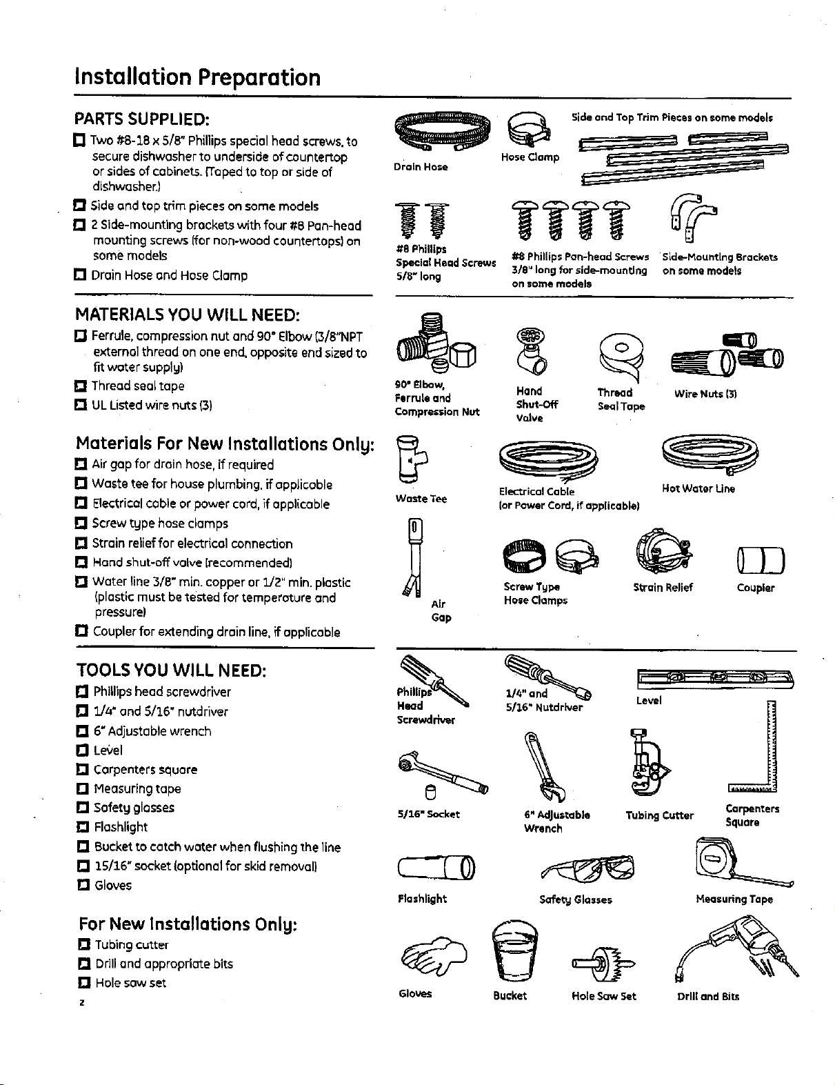
PARTS SUPPLIED:
[] Two#8-1B x 5/8" Phillipsspecialheadscrews,to
secure dishwasher to underside of countertop
or sides of cabinets_{Tapedto top or side of
Drain Hose
dishwasher.)
[] Sideandtap trim pieces on somemodels
[] Z Side-mounting brackets with four ttB Pan-head
mounting screws {fornon-wood countertopslon
some models
[] DrainHose and Hose Clamp
_t8Phillips
Special Head Screws
s/B" long
MATERIALS YOU WILL NEED:
[] Ferrule, compression nut and 90° Elbow(3/8"NPT
external thread on one end,opposite end sizedto
£rtwater supplg)
[] Threadsealtape
[] ULListed wire nuts(3)
90* Elbow,
Ferrule and
Compression Nut
Materials For New Installations Onlg:
[] Airgap for drainhose,if required
[] Waste teefor house plumbing, if applicable
[] Electricalcableorpowercord,ifapplicable WasteTee
[] Screwtype hose clamps I_
[] Strain relieffor electrical connection
[] Hand shut-off valve {recommended)
[] Water line3/8" min. copper or _J2" rain. plastic
(plastic must betested for temperatureand Air
pressure) Gap
[] Couplerfor extending drain line. if applicable
Sideand Top THm Pieces on some models
,=.. : i
HoseClamp _
#8 Phillips Pan.head Screws Side-Mounting Brackets
3/8" long for slde-mounting on some models
on _ome models
Hand
Shut-Off
Valve
Electrical Cable Hot Water Line
(or POwer Cord, if applicable}
Screw Tape Strain Relief
Hose Clamps
Thread Wire Nuts {31
Seal Tope
Coupler
TOOLS YOU WILL NEED:
[] Phillipshead screwdriver
rJ E/a"and 5/3.6" nutdriver
[] 6"Adjustable wrench
[] Level
[] Carpenterssquare
[] Measuringtape
[] Safety glosses
[] Flashlight
[] Bucket to catch water when flushing the line
[] 3.5/16"socket (optionalfor skid removal)
[] Gloves
For New Installations Onlg:
[] Tubing cutter
[] Drilland appropriate bits
[] Hole sow set
5/Z6" Nutdrlver
Level
Screwdriver
\
5/16" Socket
Flashlight
Gloves Bucket Hole Saw Set Drill and Bits
6" AdJustable
Wrench
Safety Glasses
Tubing Cutter Square
Heesuring Tape
Carpenters
Page 3
Installation Preparation
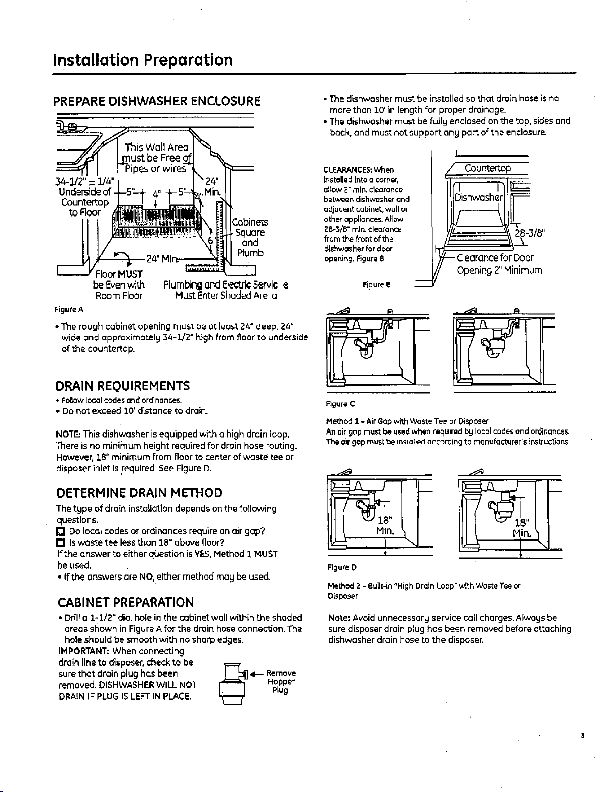
PREPARE DISHWASHER ENCLOSURE
This Wall Area
ust be Free
I_,,IPipe'
34-1/2"=1/a"J
Undersideof.
Countertop
to Floor
uore
Plumb
FloorMUST
be Evenwith
Room Floor
Figure A
• The rough cabinet opening must be at least Z4" deep. 2a"
wide and approximately 3a-1/2" high from floor to underside
of the eountectop.
DRAIN REQUIREMENTS
• FoBowlocalcodesandordinances.
• Do not e_<ceed10' distance to drain.
NOTE:This dishwasher isequippedwitha high drain loop.
Thereis no minimum height required for drain hoserouting.
However,3.8"minimumfrom floorto center ofwaste tee or
disposerinlet isrequired.SeeFigureD.
Plumbing and ElectricServic e
Hust Entershaded Are a
• The dishwasher must be installed so that drain hose isno
more than 10' in length for proper drainage.
* The dishwasher must be fully enclosed on the top, sides and
back. and must not support an_ port of the enclosure.
CLEARANCES:When
installed into o corner,
allow Z" min, deoronce
between dishwasher and
adjacentcabinet,wallor
other oppllonce_.Allow
2_-3/8" rain. clearance
from the front of the
dishwasher for door
opening. Figure8
/_ Countert.op
28-318"
.3_
- ClearanceforDoor
Opening2"Minimum
Figure8
Figure C
Hethod1 - AirGapwRhWasteTeeorDisposer
Anairgapmust beusedwhenrequired bgIoca]codesandordinances.
Theairgapmust be install_l accordingto manufacturer'sinstructions.
DETERHINE DRAIN HETHOD
The type of drain installationdependson the following
questions,
[] Dolocal codesor ordinances require on air gap?
[] Iswaste tee lessthan 18"abovefloor?.
Ifthe answerto either question isYES,Hethod 1 MUST
be used.
• Ifthe answersoreNO,either method may be used.
CABINET PREPARATION
• Drill o _,-1/2" diD. hole in the cabinet wall within the shaded
areas shown in Figure A for the drain hose connection. The
hole should be smooth with no sharp edges.
IMPORTANT: When connecting
drainline to disposer,check to be F=={
removed. DISHWASHER WILL NOT Hopper
sure that drain plug has been [_ 41-- Remove
DRAIN iF PLUG IS LEFT IN PLACE, Plug
18"
Figure D
Method 2 -Built-in "High Drain Loop" with Waste Tee or
Disposer
Note: Avoid unnecessary service callcharges. Always be
sure disposer drain plug has been removed before attaching
dishwasher drain hose to the disposer.
Page 4
Installation Preparation
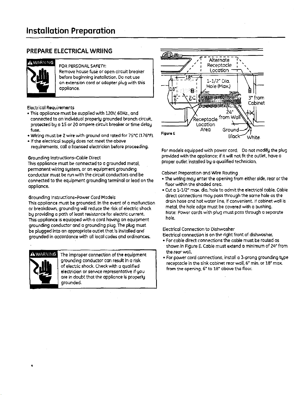
PREPAREELECTRICALWRIING
FORPERSONALSAFETY:
Removehouse fuse or open circuit breaker
before beginning installation. Do not use
an extension cord or adopter plug with this
appliance.
Electrical Requirements
• Thisappliance must be supplied with 120V,60H2_,and
connected to an individual properlg grounded branch circuit,
protected by a 15 or 20 amperecircuitbreaker or time delay
fuse,
• Wiring must be 2 wire with ground and rated for 75°C(176°F).
• Ifthe electrical supply does not meet the above
requirements, call a licensed electrician before proceeding,
Grounding Instructions-CableDirect
This appliance must be connected to agrounded metal.
permanent wiring system, or onequipmentgrounding
conductormust be run with the circuit conductorsandbe
connectedto the equipment grounding terminal or lead on the
appliance.
GroundingInstructions-Power CordModels
Thisappliance must be grounded.Inthe event of o malfunction
or breakdown, grounding will reduce the risk of electric shock
by providing a path of least resistancefor electric current,
Thisappliance isequippedwith a cordhaving onequipment
groundingconductor anda grounding plug. Theplug must
be plugged into an appropdateoutlet that is installed and
grounded in accordancewith all local codesand ordinances.
vT_lv,v/,_]_',11p 1,='1
Theimproperconnection of the equipment
grounding conductor can result in a nsk
of electric shock.Checkwith o qualified
electrician or servicerepresentativeif you
are in doubt that the appliance isproperlg
grounded,
3" from
Cobinet
Location
Figure E
Formodelsequipped with power cord: Do not modif_Jthe plug
providedwith the appliance: if it will not rr_the outlet, have a
proper outlet installed bg e qualified technician.
Cabinet Preparation and Wire Routing
• The wiring may enter the opening from eitherside.rear or the
floorwithinthe shadedarea.
• Cut o 1-1/2" max.dia. hole to admit the electrical cable. Cable
direct connections may pass through the same hole as the
drain hose and hat water line.if convenient. If cabinet wall is
metal,the ho_eedgemust be covered with a bushing.
Note: Powercords with plug must pass through a separate
hole.
ElectricalConnectionto Dishwasher
Electricalconnection is on the right front of dishwasher,
• Forcable direct connections the cobb must be routed as
shown in Figure E.Cablemust extend o minimumof 24" from
the rear well.
• Forpower cord connections, install o3-prong grounding type
receptacle inthe sink cabinet rear wall, 6"min. or 3-8"max.
from the opening, 6"to 18" above the floor.
Area Groun
White.
Page 5

Installation Instructions
PREPARE HOT WATER LINE
• The line may enterfrom either side,rear or floor withinthe
shaded area shownin FigureF.
• The line may passthrough the same hole as the electrical
cable and drain hose.Or,cuton additional l-l/Z" dia, holeto
accommodatethe water line.If powercord with plug is used,
water line must not passthrough power cord hole.
• I I •
i •
I •
i_ 1-U2" Do.
Shut-off
Hot
From
Cabinet
Cabinet
FigureF
,2" From Floor
Water Une Connection
• Turn offthe water suppl_l.
• Install a hand shut-off valvein anaccessiblelocation,such
asunder the sink,(Optional,but strongly recommended and
may be required by local codes.}
• Water connection ison the left side of the dishwasher. Install
the hot water inlet line, using no lessthan 3/8" O.D,copper
tubing_Routethe line as shown in Figure Fand extend
forward at least 19" from rear well.
- Adjust water heater for 120=Fto 3.50°Ftemperature.
• Flushwater line to cleonout debris.
• Thehot water supply linepressuremustbe 20-120 PSI.
CAUTION:
STEP 1 CHECK DOOR BALANCE
• With dishwasher on thewood skid,check the door balance
b_lopening and closing the door,
• If the door drops when released,increase the spring tension.
Ifthe door rises when released,decrease thetension.
Note:Increaseor decrease
tension asshown. Adjust
both springsto the some
tension setting to correct
ba}once. Increase
Spring
Tensior
Insert Hook
Over Bracket
Correct
Spring
Tension
incorrect
Figure G
Tip.'If doorspringadjustment is necessary, checkdoor
opening and closing.[fdoor does not open easilyor fallstoo
quickly, check spring cable routing, Thecable isheld in place
by "shoulders" on the pulley.Checkto be sure cablehasnot
slipped overthe pulley shoulders,
STEP ;t REMOVE WOOD BASE,
INSTALL LEVELING LEGS
IMPORTANT-oo notkickoffwoodbose Damage
will occur,
• Movethe dishwasher close to the installation location and lay
it on itsback.
• Removethe four leveling legs on the underside ofthe wood
bosewith on adjustable wrench or 3.5/16"socket.
• Discard bose.
Oo not ren_ve wood base until _ou are ready to instil the
dishwasher, The dlshwad_er will tip over when the door is opened
If the wood I_se Is removed.
Q BEFORE YOU BEGIN
yellow topeond stuckto thetop or sideof the dishwasher.
Removedrainhose from upper rack, if it has not been pre-
installed, and set asidefor usein Step 5A.
Locate and set aside (forusein Step_.Z)the
2 Phillipsspecial head screws wrapped with
Figure H
•Screwleveling legs backinto the dishwasher frame,
oppro×imotely 1/4" from frame as shown,
Page 6

Installation Instructions
STEP 3 REMOVE TOEKICK
• Removethe
2 toekick screws
and toekick.
Setasidefor use
inStep16
FigureI Toekick Screws
STEP 4 INSTALL POWER CORD
Skipthis step ifdishwasher will bedirect wired or has o
factors installed power cord.
Use Power CordKitWxogx70910, available for purchase
from on authorized GEAppliance Dealer.Thepower cord and
connectionsmust comply with the National Electrical Code,
Section a.ZZand/or local codesand ordinances,
• Maximum power cordlength is6'.
A C
Remove Insert Power
Junction Box
Cover Strain Relief
and TightenGround
Check That White, Black and
Green Dishwasher Wires Are D
Threaded Thru Small Use UL Listed
Hole in Bracket Wire Nuts
Remove 2
White
,Block
STEP5 INSTALL 90" ELBOW
•Wrap g0°elbow with thread seal tope.
• Install a 90" elbow onto the water valve.
• Do not overtighten 90° elbow. Front of Dishwasher
Water valve bracket could {_
bendor wotel:valve _,
_tting could break_ "1
• Positionthe end of _ I _r'_
the elbowto face F _J.J._- _ __
the rear ofthe /' 1
dishwasher. | _.J Water Valve
I _____ _ Bracket
Elbow90'_.I_i_ - I I
I -- \ I_ Fill
o
_ Thread
_guteK "_ SeolTope
STEPSA INSTALL DRAIN HOSE TO
DISHWASHER DRAIN PORT
Skipthis step if drain hosehas beenpre-installed. In
this step you will need the drainhoseset aside prior
to Step 1.
• Remove hose damp attached to drain hose.Placehose
clamp overthe small end of the drain hose,
Tip: Preventdrain hose damage and possible leaks.
Be careful not to nick or cut the drain hose.
• Pushthe small end of the drain hoseover the drain port of
the dishwasher,see Figure L.
• Makesure hose isfull_ seated on the dishwasher drain port.
• Positionhose clamp against the front lipof the drain hose
andtighten clornp:
Figure J
* Connect incoming power cord white (orribbed)to dishwasher
white, black(orsmooth)to blackand ground to dishwasher
green wire. Use ULlisted wire nuts of appropriate size.
• Replacejunction boxcover•Besure wires ore not pinched
• under the cover.
G
Hose
Figure L
Page 7

Installation Instructions
STEP 6 POSITION WATER LINE
AND HOUSE WIRING
• Positionwater supplyline and housewiring on the floor of
the opening to ovoid interference with bose of dishwasher
and componentsunder dishwasher.
STEP 8 SLIDE DISHWASHER
PARTIALLYINTO CABINET.
DONOTPUSHAGAINSTFRONTPANELWITHKNEES.DAMAGE
WILLOCCUR.
• Slidedishwasher into the openingo few inchesat a time.
_" sH I-S" _"
I I ,//_ House ._.._ _x H
I[ /_' VVater Wiring _L_ _ JI )o Not PushAgainst
=:::5/- uoo Fron,ooorPone,Wi,h
Figure M
Figure O
• Asyou proceed, pull the drain hosethrough the opening
STEP 7 INSERT DRAIN HOSE
THROUGH CABINET
• Turn the dishwasheruprightand positionin frontof the
opening.Insertdrainhoseinto the hole in cabinetside.Ifo
power cordisused,guidethe endthrough oseparatehole.
• Make sure drain hose is not kinked under the dishwasher and
Knee. Damage toThe
Door PanelWillOccur.
under the sink.Stoppushingwhen the dishwasher iso few
inchesforward of adjacent cabinets.
there is no interferencewith the water line and wiring or any
other component.
STEP 9 INSTALL TRIM PIECES
,Hose Length10'
Blanket
Skipthis step if trim isnotsupplied withthe dishwasher.
• Locate trim strips insidedishwasher.
• Presstrim onto the tub flangeon eachside,Start with the top
edge,pressing on es gou move towards the bottom.
- Pressthe two top tdm pieceson each sideof the latch,
• Open and closethe door to checkthat trim doesnot bind and
doesnot interfere with doorlatch.
Wiring
Power Cord
(If Used)
Rgure N
rip: Positionwater line end housewiring on the floor to avoid
interference with baseof dishwasher.
Trim
Figure P
Page 8

Installation Instructions
STEP 9A INSTALL SIDE-HaUNT
BRACKETS(included with
some models)
Skipthis stepif undersideof €ountertop iswood or
wood-like material
• Installside-mount bracketsif undersideof countertop is
granite or similar materiel that will not accept wood screws.
The bracket kit is located in the Owner'sManual bog on
modelswith thisfeature,
Note: The bracketsore available for purchasewhen
neededfor models not foctorg equippedwith the sidemount
kit. Order pert GPF65from gour authorized GEAppliance
Dealer.
• Fasten the left-hand bracket to the left side
of the dishwasher frame. Fasten the
right-hand bracket to the right side of the
dishwasher frame, using the #8 pan-bead
screws included with the kit. Refer to Side-Mounting
Step 12, Figure U for orientotlon Bracketson
and placement.
fame model_
STEP 10 PUSH DISHWASHER INTO
FINAL POSITION
Tip: Check tub insulation blanket, if equipped. It should be
positioned so it is not "bunched up" or interfering with door
springs. Check bg opening and closing door.
• Push dishwasher into the cabinet. The edges of the
dishwasher door should be behind the cabinet frame and
evenlg aligned with the front face of cob)net doors.
• ¢orefull_l open and close the door to ensure the door panel is
not catching or rubbing on the cabinet frame,
STEP 11 LEVEL DISHWASHER
IMPORTANT - Dishw°shermustbelevel
for proper dish rock operation and wash performance.
• Place level on door and rock track as shown• Check to make
sure that the dishwasher is level,
Check
Level- Check
Front-
to-Boc(, Leve_
Figure R
• Level the dishwasher bg adjusting the four leveling legs
individuallu.
• If adjustment to the right rear leveling leg is required, loosen
junction box brecket screw (through the access hole) and
rotate bracket clockwise.
Tip: Pull lower rock out, about halfwo g. Check to be sure the
rock does not roll forward or back into dlshwosher. Ifthe rock
mils in either direction, the dishwasher must be leveled again.
• if door hits tub, the dishwasher is not installed correctly.
Adjust leveling legs to anon door to tub.
Door
Fitsand
Swings
Book
Behind
Cabinet
Frame
Alignment
Figure Q
Correct
Door Catches
Cobinet Frame
nment
J. Box Access Hole I
Figure$
Page 9

Installation Instructions
STEP 12 POSITION DISHWASHER, SECURE TO COUNTERTOP OR CABINET
In this step gou wiU need the 2 Phillips special head He_hod 2
screws set aside prior to Step 1. Secure dishwasher to cabinet sides
The dishwasher must be secured to the €ountertop or the • Recheck alignment of the dishwasher in the cabinet, Refer
cabinet sides. When the underside of the countertop is wood, to Step 10. Figure Q and Step 11, Door panel and/or control
use Hethod 1, Use Method 2 when the underside of the panel must not hit cabinets or countertop.
countertop is made of a material, such as granite, that will not . Fasten the dishwasher to the adjacent cabinets with the
accept wood screws.
Tip: Prevent door panel and control panel damage. Dishwasher
must be positioned so the front panel and control panel do not
contact the adjacent cabinets or €ountertop. HounUng screws
must be driven straight and flush, Protruding,screw heads
could scratch the door panel or control panel and interfere
with door operation.
Hethod 1
Secure dishwasher to underside of wood countertop.
• Recheck alignment of the dishwasher in the cabinet. Refer
to Step 10, Figure Qend Step 11. Door panel eed/or control
panel must not hit cabinets or €ountertop.
• Fasten the dishwasher to the underside of the countertop
with the 2 Phillips special head screws provided. Refer to
Figure 1",Hake certain screws ore driven straight and flush to
prevent panel damage.
2 Phillips special head screws provided. Refer to Figures U
and V. Hake certain screws are driven straight and flush to
prevent panel damage.
Mounting _----_'__
T,,h _r,,m= ( /"At_- _" Countertop
.... _'_ t _ Moun'dng
"_" ,. Rrnckpt Brackets
I _="_'_ -- 8racket
J I _ Attachment
I _ Screws
(2 Each
FigureU Side)
Brockef._ Wood Co,untertop
//frT
Figure T
STEP 13 CONNECT WATER SUPPLY
Connect water supplg line to 90 ° elbow,,
- Slide compression nut, then ferrule over end of water line.
• Insert water line into 90" elbow.
* Slide ferrule against elbow and secure with compression nut.
IH PORTANT- Checkto be sure that door springdoes
not rub or contact the fill hoseor water supplg line.Testbu
openingand closingthe door.Reroutethe linesIf necessartj.
Gronite Countertop
./
Figure v
Suppl U Line
Door 90" Elbow
Spring
FigureW
Page 10

Installation Instructions
STEP 14 CONNECT DRAIN LINE
FOLLOWALL LOCALCODESANDORDINANCES.
Identifg the tape ofdrain hose you hove.The molded end of
the drainhosewillfit 5/8"through 1_diameterinlet portson
the air gap,wastetee ordisposer.
• Determinesizeofinlet port
• Cut drain hoseconnector onthe marked line,if required, to _t
the inlet port,
TYPE1
Cutting Line
IMPORTANT: Do notcut corrugated portion of hose
TYPE 2
Cutting Lines
DRAIN LINE INSTALLATION
• Connectdrainlinetoair gap,wastetee ordisposer using
either previous]gdetermined method.
Method 3,- Airgap with wastetee or disposer
WasteTeeInstallation
Figure Z
Method 2 - Built-in"High droin loop" with waste tee or
disposer
DisposerInstallation
IMPORTANT: Do notcutcorrugatedportionofhose
Figure X
• If a longer drain hoseis required, oddup to 42" of length for
a total of 3.0'to the foctorg installed hose. Use5/8" or 7/8"
insidediameterhoseand e coupler to connect the twohose
ends.Securethe connectionwith hose clamps,
Coupler
Hose Clamp
Figure Y
•Securethe drain hoseto the air gap.wastetee ordisposer
with clamps.
Note:.TOTAL DRAIN HOSE LENGTH MUST NOT EXCEED 10 FEET
FOR PROPER DRAIN OPERATION.
Waste Tee Installation
FigureAA
DisposerInstandtion
IMPO RTANT- Whenconne=ingdrainlineto
disposer,checktobesurethatthedrainplughasbeen
removed. DISHWASHERWILL NOTDRAINIFPLUGISLEFTIN
PLACE.
4-- emove
Hopper
Plug
Tip:Avoidunnecessorg service coil charges. Alwogs be sure
disposer droin plug has been removed before ottoching
dishwasher droin hose to the disposer.
%O
Page 11

Installation Instructions
STEP 15 CONNECT POWER SUPPLY
Skip this step if dishwasher is equipped with power cord.
Verifg that power is turned off at the source.
If e power cord with plug is used. proceed to Step 16.
• Removejunctlon box cover.
• Secure house wiring to the back of the junction box with a
strain relief, []
• Locate the three dishwasher wires, (white,blockand green) []
with stripped ends. Insert dishwasherwiresthroughthe small
holein thejunction box.Usewire nutsto connectincoming
groundto green,white to white and blockto black.
• Replacejunction box cover.Checkto be surethat wiresare
not pinchedunderthe cover.
Remove Insert Powe
JUnction Box Cord WiresThru _ J
Cover Strain Relief
CheckThat White, Block IE_ q
and Green Dishwasher._4-37_ _ J
Wires Are Threaded D
Thru Small HoLe in Bracket Use UL Listed
Wire Nuts
Figuree8
If house wiring isnot 2-wire with ground,a
ground must be providedbg the installer.
When housewiring is aluminum, besureto
useULListedanti-oxidant compoundand
aluminum- to-copper connectors
STEP 16 PRETESTCHECK LIST
Review this list after instulling pour dishwasher to
avoid charges for o service coil that is not covered by your
wurrontg.
[] Check to be sure power is OFF.
Open door and remove all foam and paper packaging.
Locatethe Owner's Manual in the literature package.
[] Road the Owner's Hanual for operating instructions.
[] Check door opening and closing, if door does not open end
close freelg, check for proper routing of spring cable over
pulleU. If door drops or closes when released, adjust spring
tension. See Step 1,Figure G.
[] Check to be sure that wiring is secure under the dishwasher,
not pinched or in contact with door springs or other
components. See Step 8.
[] Check door alignment with tub. If door hits tub, level
dishwasher. See Steps ll and 12.
[] Pull lower rack out, about holfwag. Check to be sure it does
not roll beck or forward on the door. If the rack moves,
adjust leveling legs.See step 11.
[] Check door alignment with cabinet. If door hits cabinet,
reposition dishwasher, See Step 12.
[] check that doorspring doesnot contact water line, fillhose,
wiring or other components.SeeStep $3.
[] Verifg water supplg and drain lines a re not kinked or in
contact with other components. Contact with motor or
dishwasher frame could cause noise.
[] Turn on the sink hot water faucet and verifg water
temperature. Incoming water temperature must
be between 120"F and :[S0"F. Aminimum of 120"F
temperature is required for best wash performoeee. See
"Prepare Hot Water Line," page S.
[] Add 2 quarts of water to the bottom of the dishwasher to
lubricate the pump seal.
[] Turn on water supplg. Check for leaks. Tighten connections
if needed,
[] Removeprotectivefilm if presentfrom the controlpanel
and door.
t%
Page 12

Installation Instructions
STEP 17 DISHWASHER WET TEST
[] Turnon powersupplgJarplugpowercordintooutlet,
if equipped).
[] Latchdoor.
[] Push"RinseOnlg" utton.
[] PushStart/Reset pad once, Dishwashershouldstart.
[] Checkto e sure that water enters the dishwasher.If water
does not enter the dishwasher,check to e surethat water
and power ore turned on.
n Checkfor leaks under the dishwasher.If o leek isfound, turn
offpower supplg,then tighten connections.Restorepower
after leak iscorrected.
[] Checkforleaksaroundthedoor.A leakaroundthedoor
coulde causedg doorruingorhittingagainst
adjacentcainets,Repositionthedishwasherifnecessarg.
SeeStep12.
[] Thedishwasher willdrain and turn off aout 5 minutes after
itwas started. Checkdrain lines.If leaks are found, turn off
power atthereaker and correctplumingasnecessarg.
Restorepower after correctionsoremade. SeeSteps5A
and la,
[] Open dishwasher door and make sure most of the water
has drained, If not. check that disposer plug has een
removed and/or airgap isnotplugged.See Step Ij'.
[] PressStart/Reset pad onceagain and run dishwasher
through another "RinseOnlg" cgcle,Checkfor leeks and
correct if required.
STEP 18 REPLACE TOEKICK
• Placetoekick against the legs ofthe dishwasher,
Screws
Figure CC
• Align the toekick withthe attain edge and make sureit is
against the floon
•insert andtightenthetwo toekickattachmentscrews.The
toekickshouldstagincontactwiththefloor.
Tip: Makesure toekick isagainst floor to minimize noise.
STEP 19 LITERATURE
• Besureto leave complete literature package and Installation
Instructions with the consumer.
SPECIFICATIONSSUBJECT TO CHANGE WITHOUT NOTICE
GEConsumer&_Industrial
GeneralElectdcCompang
Louisville,Kentuckg _0275
g_com
© 2OOS General Electric Compang
Pub.No.31-30579
Dwg.No.20SC$SSgP%$9
NO 05A-1182 lP./O5)Roy,2
 Loading...