

Page 1

GE Fanuc Automation
Programmable Control Products
Series 90t-70
I/O Link
Interface Module
GFK–0644A February 1993
Page 2

Warnings, Cautions, and Notes
as Used in this Publication
Warning notices are used in this publication to emphasize that hazardous voltages,
currents, temperatures, or other conditions that could cause personal injury exist in this
equipment or may be associated with its use.
In situations where inattention could cause either personal injury or damage to
equipment, a Warning notice is used.
Caution notices are used where equipment might be damaged if care is not taken.
GFL–002
Warning
Caution
Note
Notes merely call attention to information that is especially significant to understanding
and operating the equipment.
This document is based on information available at the time of its publication. While
efforts have been made to be accurate, the information contained herein does not
purport to cover all details or variations in hardware or software, nor to provide for
every possible contingency in connection with installation, operation, or maintenance.
Features may be described herein which are not present in all hardware and software
systems. GE Fanuc Automation assumes no obligation of notice to holders of this
document with respect to changes subsequently made.
GE Fanuc Automation makes no representation or warranty, expressed, implied, or
statutory with respect to, and assumes no responsibility for the accuracy, completeness,
sufficiency, or usefulness of the information contained herein. No warranties of
merchantability or fitness for purpose shall apply.
The following are trademarks of GE Fanuc Automation North America, Inc.
Alar m Master CIMST AR Helpmate PROMA CRO Series Six
CIMPLICITY Field Control GEnet Logicmaster Series One
Series 90 CIMPLICITY 90–ADS Genius Modelmaster Series Three
VuMaster CIMPLICITY PowerTRA C Genius PowerTRA C ProLoop Series Five
Workmaster
Copyright 1993 GE F anuc A utomation North America, Inc.
All Rights Reserved
Page 3

Content of this Manual
This book is a reference to the features, operation, installation, and configuration of the
GE Fanuc Series 90t-70 I/O Link Interface Module (IC697BEM721).
Chapter 1. Introduction: Describes the functions and features of the Series 90-70 I/O
Link Interface Module.
Chapter 2. Installation: Includes basic setup procedures.
Chapter 3. Series 90-70 PLC Configuration: Shows how to add an I/O Link Interface
Module to the Series 90-70 PLC system.
Chapter 4. Series 90-70 PLC Programming: Explains how to configure, monitor, and
control the I/O Link Interface Module.
Related Publications
Logicmaster 90-70 Users’s Manual (GFK–0263). Reference manual for system operators
and others using the Logicmaster 90-70 software to program, configure, monitor, or
control a Series 90-70 PLC and/or a remote drop.
Preface
Power Mate Connection, Programming, Maintenance Manual (GFZ–61613). Reference
manual to setting up, programming, operating, and maintaining a P ower Mate system.
Series Zero Connection Manuals. For 0 and 00-TC, TF, TTC, MC, MF, GCC, GSC, and PC
controls, the connection manual is GFK–61393. For 0-L and 00-L controls, the connection
manual is GFZ-61573.
Series Zero Operator Manuals. For 0 and 00- TC, TF, TTC, and GCC controls, the operator
manual is GFZ-61394. For 0 and 00-MC, MF, and GSC controls, the operator manual is
GFZ-61404. For 0-PC and 00-PC controls, the operator manual is GFZ-61594. For 0-L and
00-L controls, the operator manual is GFZ-61574.
Series 15 Connection Manual (GFZ-61213E).
Series 15 Operator/Programming Manual (GFZ-61213E).
Series 16 Connection Manual (GFZ-61874E).
Series 16 Operator Manuals. For the 16-MA control, the operator manual is GFZ-61874. F or
16-TA and 16-TTA controls, the operator manual is GFZ-61804.
Series 16 Maintenance Manual (GFZ-61805).
We Welcome Your Comments and Suggestions
At GE Fanuc automation, we strive to produce quality technical documentation. After
you have used this manual, please take a few moments to complete and return the
Reader’s Comment Card located on the next page.
Jeanne Grimsby
senior technical writer
GFK–0644A
iii
Page 4

Chapter 1 Introduction 1 . . . . . . . . . . . . . . . . . . . . . . . . . . . . . . . . . . . . . . . . . . . . . . .
System Overview 1 . . . . . . . . . . . . . . . . . . . . . . . . . . . . . . . . . . . . . . . . . . . . . . . . .
Application Software 3 . . . . . . . . . . . . . . . . . . . . . . . . . . . . . . . . . . . . . . . . . . . . . .
Module Description 4 . . . . . . . . . . . . . . . . . . . . . . . . . . . . . . . . . . . . . . . . . . . . . . .
Module Specifications 5 . . . . . . . . . . . . . . . . . . . . . . . . . . . . . . . . . . . . . . . . . . . . .
Cable T ypes for the I/O Link 6 . . . . . . . . . . . . . . . . . . . . . . . . . . . . . . . . . . . . . . . .
Optical Adapter 8 . . . . . . . . . . . . . . . . . . . . . . . . . . . . . . . . . . . . . . . . . . . . . . . . . .
Operation of the I/O Link 9 . . . . . . . . . . . . . . . . . . . . . . . . . . . . . . . . . . . . . . . . . .
Getting Started 14 . . . . . . . . . . . . . . . . . . . . . . . . . . . . . . . . . . . . . . . . . . . . . . . . . . .
Chapter 2 Installation 15 . . . . . . . . . . . . . . . . . . . . . . . . . . . . . . . . . . . . . . . . . . . . . . . .
Installing the I/O Link Interface Module in the Rack 15 . . . . . . . . . . . . . . . . . . .
Removing the I/O Link Interface Module from the Rack 16 . . . . . . . . . . . . . . .
Connecting the I/O Link Interface Module to Other Devices 17 . . . . . . . . . . . .
Serial Port Pin Assignments 18 . . . . . . . . . . . . . . . . . . . . . . . . . . . . . . . . . . . . . . . .
Optical Adapter Installation 20 . . . . . . . . . . . . . . . . . . . . . . . . . . . . . . . . . . . . . . . .
Contents
Chapter 3 Logicmaster 90-70 Configuration 21 . . . . . . . . . . . . . . . . . . . . . . . . . . . . .
Chapter 4 Programming Guide 23 . . . . . . . . . . . . . . . . . . . . . . . . . . . . . . . . . . . . . . . .
Overview 23 . . . . . . . . . . . . . . . . . . . . . . . . . . . . . . . . . . . . . . . . . . . . . . . . . . . . . . .
Selecting a Program Block 24 . . . . . . . . . . . . . . . . . . . . . . . . . . . . . . . . . . . . . . . . . .
A dding the Program Block Logic to an Application Program 24 . . . . . . . . . . . .
Calling the Program Block 25 . . . . . . . . . . . . . . . . . . . . . . . . . . . . . . . . . . . . . . . . .
Program (%P) References for the I/O Link Program Blocks 26 . . . . . . . . . . . . .
Global (%G) References for the I/O Link Program Blocks 27 . . . . . . . . . . . . . . .
Configuring I/O Links 28 . . . . . . . . . . . . . . . . . . . . . . . . . . . . . . . . . . . . . . . . . . . . .
Controlling the I/O Link Module 30 . . . . . . . . . . . . . . . . . . . . . . . . . . . . . . . . . . .
Monitoring Link Operation 32 . . . . . . . . . . . . . . . . . . . . . . . . . . . . . . . . . . . . . . . .
GFK–0644A Series 90-70 I/O Link Interface Module User’s Manual - February 1993
iv
Page 5
restart lowapp ARestart oddapp: ARestarts for autonumbers that do not restart in
each chapter . figure bi level 1, reset table_big level 1, reset chap_big level 1, reset1
Lowapp Alwbox restart evenap:A1app_big level 1, resetA figure_ap level 1, reset
table_ap level 1, reset figure level 1, reset Figure 1. table level 1, reset Table 1.
these restarts oddbox reset: 1evenbox reset: 1must be in the header frame of
chapter 1. a:ebx, l 1 resetA a:obx:l 1, resetA a:bigbx level 1 resetA a:ftr level 1 resetA
c:ebx, l 1 reset1 c:obx:l 1, reset1 c:bigbx level 1 reset1 c:ftr level 1 reset1
Reminders for autonumbers that need to be restarted manually (first instance will
always be 4) let_in level 1: A. B. C. letter level 1:A.B.C. num level 1: 1. 2. 3.
num_in level 1: 1. 2. 3. rom_in level 1: I. II. III. roman level 1: I. II. III. steps level 1:
1. 2. 3.
Chapter 1 Introduction
section level 1 1
1
System Overview
figure bi level 1
table_big level 1
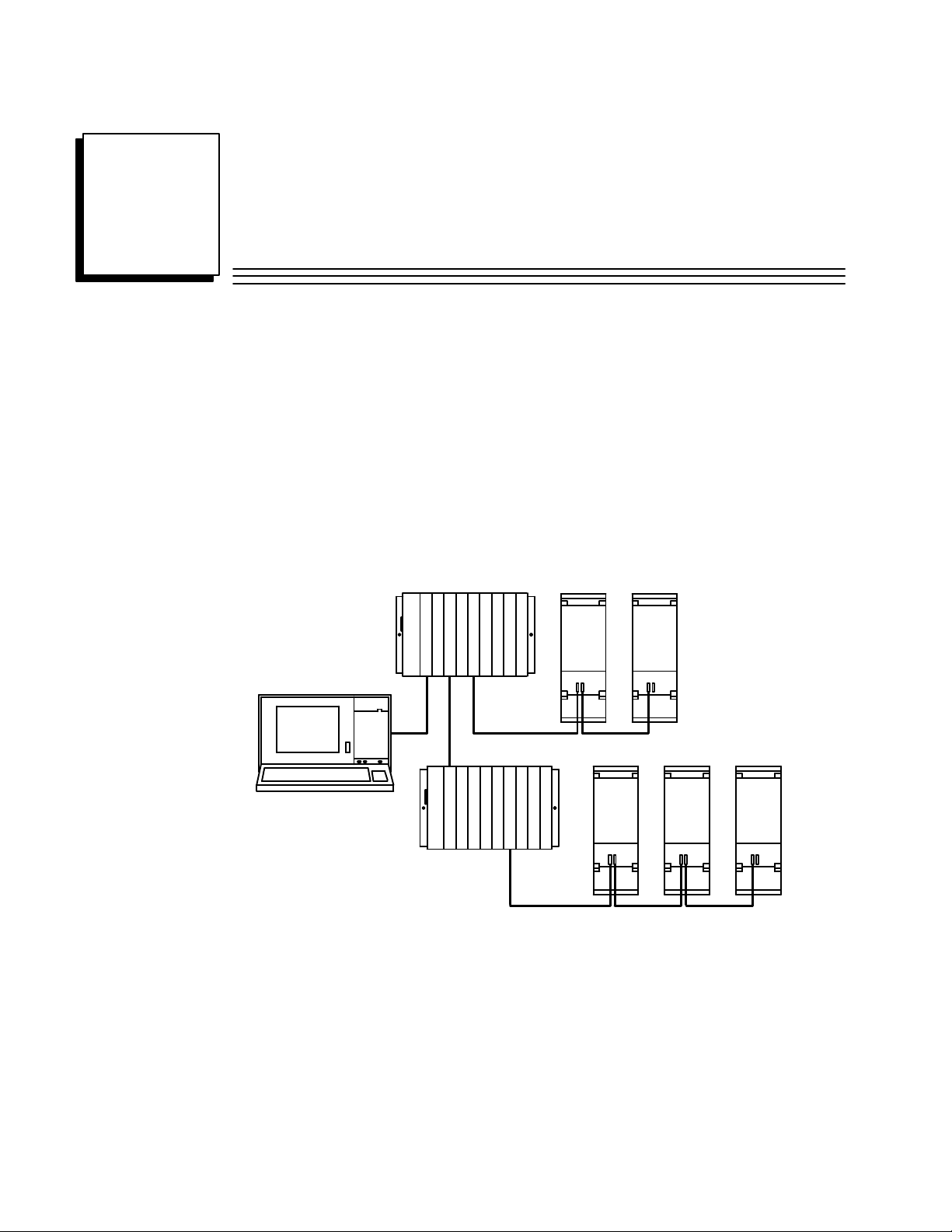
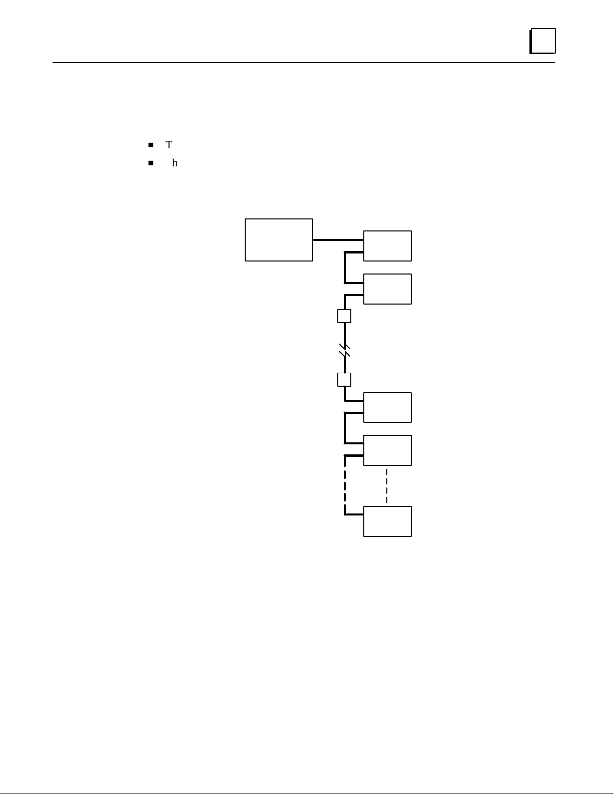
The Series 90–70 I/O Link Interface Module (IC697BEM721) is used to interface a Series
90–70 PLC to GE Fanuc and Fanuc products which may also be placed on the
proprietary Fanuc I/O Link. The Fanuc I/O Link is a serial interface that provides
high–speed exchange of I/O data between a master device and up to 16 slaves.
a44979SERIES 90–70 PLC
WORKMASTER II
PROGRAMMER
PS
CPU
MASTER
BTM
PS
BRM
I/O LINK
I/O LINK
(LINK #1)
MASTER
FANUC
I/O LINK
POWER MATE POWER MATE
SLAVE 0 SLAVE 1
POWER MATE
SLAVE 0
FANUC
I/O LINK
(LINK #2)
POWER MATE POWER MATE
SLAVE 1 SLAVE 2
Up to four I/O Link Interface Modules can be installed in a Series 90–70 PLC. They can
be located in the CPU rack and in expansion racks. Each I/O Link Interface Module can
be used in either master or slave mode.
GFK-0644A
Two I/O Link Interface Modules are shown in the example system illustrated
above––one in the CPU rack and the other in an expansion rack. Each module is set up
as a master with its own I/O Link. In this example, both of the I/O Link Interface
Modules exchange data with P ower Mate CNCs. Usually, when there are multiple I/O
Link Modules in the same PLC, they are on separate I/O Links as shown here. However,
it is possible to have more than one I/O Link Interface Module in the Series 90–70
connected to the same link, if that suits the needs of the application.
1
Page 6
1
Master or Slave Operation
When used as a master, an I/O Link Interface Module can receive up to 1024 discrete
inputs from devices on the I/O Link, and send up to 1024 discrete outputs. P otential
slave devices include the Series 90–30 PLC and the Power Mate CNC.
When used as a slave, the Series 90–70 I/O Link Interface Module can receive up to 64
discrete inputs from the master, and send up to 64 discrete outputs. The master may be
another Series 90–70 PLC, a Series 15, Series 16, or Series 18 CNC, a Series 0 Model C
CNC, or an F–D Mate CNC. The Series 90–70 PLC and Series 0 CNC can be used as
either master or slave.
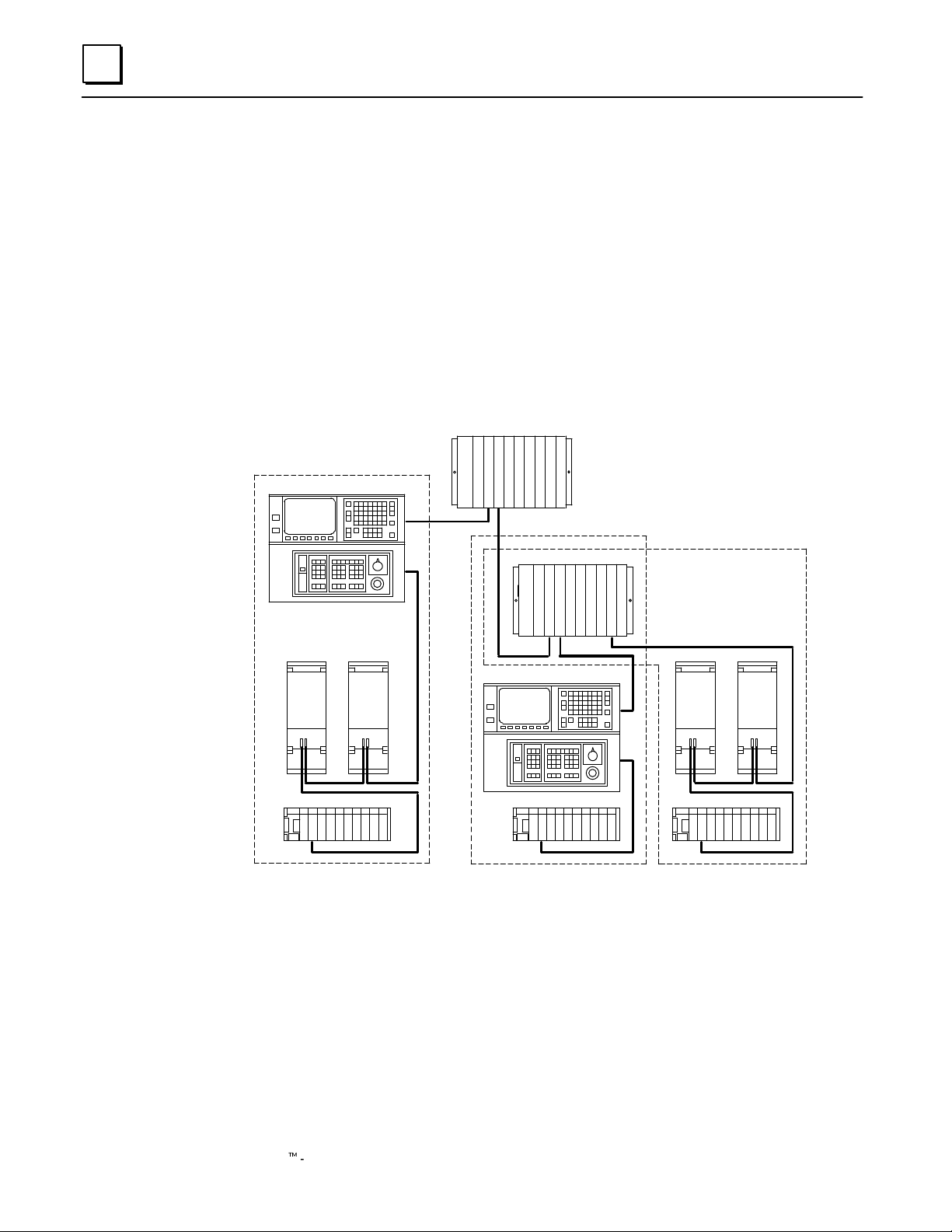
In the example system shown below, the Series 90–70 PLC shown at the top functions
as an area controller for three machine cells. The area controller has two I/O Link
Interface Modules, each of which operates as an I/O Link master.
SERIES 0 CNC
POWER MATE POWER MATE
CELL #1
AREA CONTROLLER
SERIES 90–70 PLC
I/O LINK
I/O LINK
I/O LINK
I/O LINK
CELL #2
SERIES 90–70 PLC
I/O LINK
I/O LINK
I/O LINK
SERIES 0 CNC
a45002
CELL #3
I/O LINK
I/O LINK
POWER MATE POWER MATE
SERIES 90–30 PLCSERIES 90–30 PLCSERIES 90–30 PLC
In this system, the left I/O Link from the area controller goes to cell 1, where a Series 0
CNC, two single–axis Power Mate CNCs, and a Series 90–30 PLC are the slaves. They
control the operations of a large machine and its auxiliary equipment. The right I/O Link
from the area controller goes to another Series 90–70 PLC. That PLC serves as a slave
on the link to the area controller, and as a master on two other links to smaller machine
cells. In cell 2, a Series 0 CNC and a Series 90–30 PLC are the slaves. In machine cell 3,
the slaves are a Series 90–30 PLC and two Power Mate CNCs.
2 Series 90t-70 I/O Link Interface Module User’s Manual – February 1993
GFK-0644A
Page 7

Application Software
The Series 90–70 I/O Link Interface Module is provided with two application software
diskettes (catalog number IC641SWP708), a 3-inch and a 5-inch diskette. The content
of these diskettes is the same.
This application software can be used to integrate up to four I/O Link Interface Modules
into the PLC’s application program. There are three Program Blocks on a diskette. Each
will transfer I/O data between the module and the PLC, perform diagnostics functions,
and transfer application program commands to the module.
One Program Block is selected as being most appropriate for the application, and added
to the application program. Additional application program logic can be created to
perform the following functions:
1. To specify the number of I/O Link Interface Modules present in the PLC.
2. To specify, for each I/O Link Interface Module:
A. A rack and slot location in the Series 90–70 PLC.
B. Master or slave operation.
1
3. And, for each I/O Link Interface Module that will be a master:
A. T o assign a data length and I/O addresses for each slave on its link.
B. To control operation of the link and monitor module and link status.
Chapter 4 explains how to select the best Program Block for your system, and how to
incorporate it in an application program.
3GFK–0644A Chapter 1 Introduction
Page 8
1
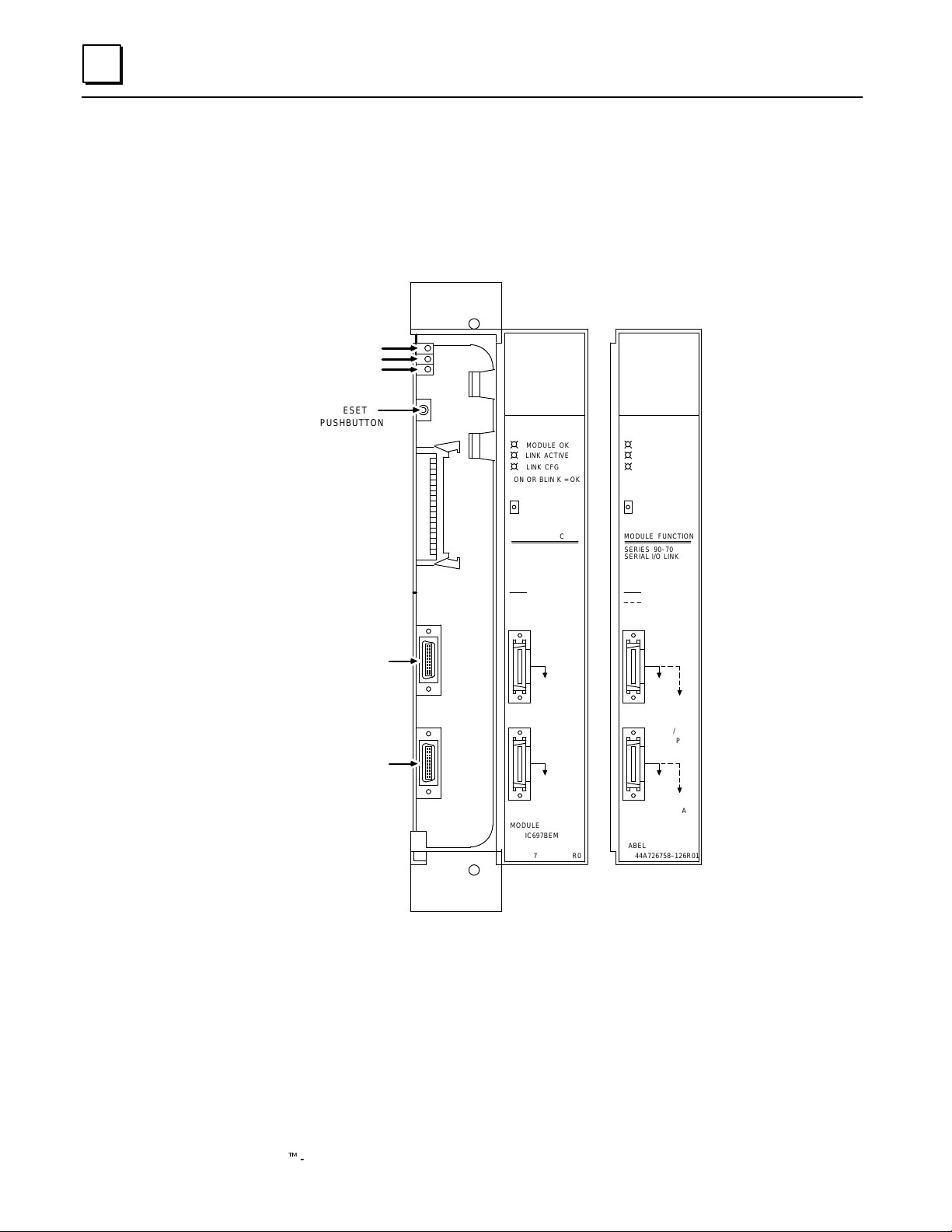
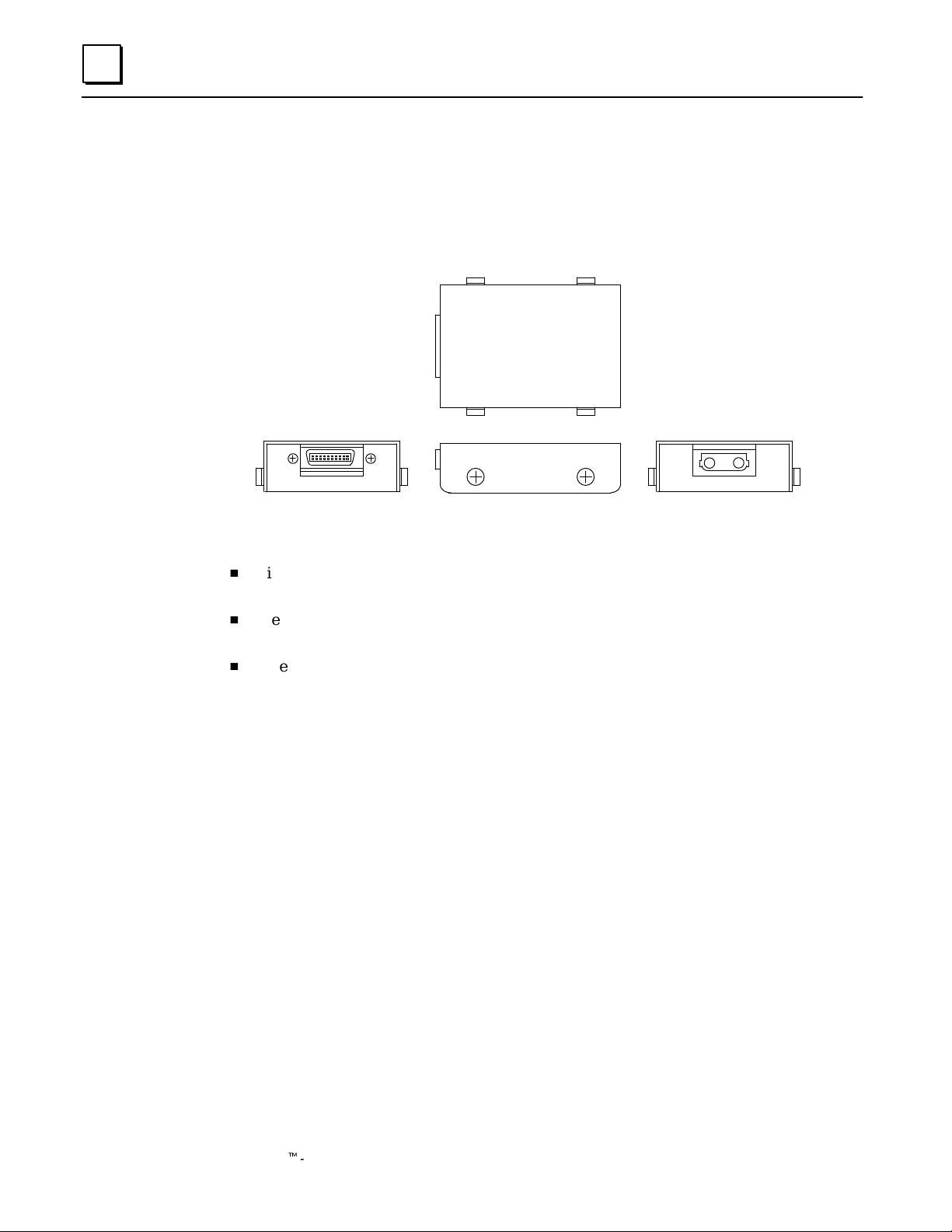
Module Description
An I/O Link Interface Module occupies one module slot in a Series 90–70 PLC rack. It
can be installed in any rack, in any slot except rack 0 slot 1, which is reserved for the CPU
Module.
MODULE OK
LINK ACTIVE
LINK CFG
RESET
PUSHBUTTON
MODEL 70
BEM 721
MODULE OK
LINK ACTIVE
LINK CFG
ON OR BLIN K = OK
PUSH TO RESET
I/O LINK
INTERFACE
MODULE FUNCTION
SERIES 90–70
SERIAL I/O LINK
INTERFACE
a45015
MODEL 70
BEM 721
MODULE OK
LINK ACTIVE
LINK CFG
ON OR BLIN K = OK
PUSH TO RESET
I/O LINK
INTERFACE
MODULE FUNCTION
SERIES 90–70
SERIAL I/O LINK
INTERFACE
RS–422/485
CONNECTOR
RS–422/485
CONNECTOR
: MASTER MODE
RS–422/485
SERIAL PORT
NEXT
(JD1A)
RS–422/485
SERIAL PORT
NOT
USED
MODULE
IC697BEM721
LABEL
44A726758–125R01
: MASTER MODE
: SLAVE MODE
RS–422/485
SERIAL PORT
NEXT
(JD1A)
PREVIOUS
(JD1A)
RS–422/485
SERIAL PORT
NOT
USED
NEXT
(JD1A)
MODULE
IC697BEM721
LABEL
44A726758–126R01
LEDs
The I/O Link Interface Module has three LEDS that show its operating, configuration,
and communications status.
Module OK: indicates the module’s operating status.
Link Active: indicates the module’s communications status.
Link Cfg: indicates whether I/O Link configuration has occurred.
4 Series 90t-70 I/O Link Interface Module User’s Manual – February 1993
GFK-0644A
Page 9

Reset Pushbutton
The Reset pushbutton provides a convenient means of reset if a failure occurs. If the
module is being used as a master, pushing the Reset button resets both the module and
operation of the link. The application program must be used to re–initialize the link. If
the module is being used as a slave and a fault has caused the module to stop operating,
pushing the Reset button resets the module while the rest of the link continues to
function.
Note
The Reset pushbutton should not be used if the link is operating
normally. Pressing Reset during normal operation causes the link to
stop operating. The diagnostic program logic interprets this as an
external link failure.
Serial Ports
The front of the module has two 20–pin, D connector, RS–422/485 serial ports. These
ports are used for connection to the I/O Link.
1
Module Specifications
Physical dimensions: 6.3in x 9.19in (160mm x 233mm).
Module type: Series 90–70 PLC module, providing I/O Link commu-
Current requir ement from +5–volt bus 1.0 Amp without Optical Adapter.
LEDs: Module OK, I/O Link Active, I/O Link Configured
Pushbutton: Reset I/O Link
I/O Points:
In master mode
In slave mode
Environmental:
Operating temperature
Storage temperature
Humidity
V ibration and shock
Occupies single slot in Series 90–70 rack.
nications with up to 16 slave devices in master mode.
0.2 Amp per Optical Adapter.
1024 inputs, 1024 outputs maximum
64 inputs, 64 outputs maximum
0ºC to +60ºC (32ºF to +140ºF)
–40ºC to +85ºC (–40ºF to +185ºF)
5% to 95% (non–condensing)
3.5mm displacement 5–9Hz
1 G 10–200Hz
15G for 11mS duration
RS–422/485 Serial Ports: 1.5 MHz transmission rate.
5GFK–0644A Chapter 1 Introduction
Page 10
1
Cable Types for the I/O Link
The following cables and connectors can be used to complete the I/O Link between
devices.
Item Catalog Number V endor Description
Cable A03B–0807–K801 GE Fanuc 5 meter length with connectors on both ends.
Cable A03B–0807–K802 GE Fanuc 10 meter length with connectors on both ends.
Connects between master and slave device, or
between two slave devices.
Connects between master and slave device, or
between two slave devices.
Cable AMW 2076 OKI
Electric
Cable
Connector A02B–0120–K301 GE Fanuc 20–pin connector with solder lug. Consists of
Connector PCR–E20FS Honda 20–pin female connector with solder lug.
PRC–V20L Honda Connector cover.
Cable A03B–0807–K803 GE Fanuc 1 meter length with connectors on both ends.
Optical
A dapter
Cable A66L–6001–009 GE Fanuc Optical fiber cable for use with Optical
A138–154–B001 GE Fanuc Required for optical fiber cable.
” #L10R03
” #L15R03
” #L20R03
” #L30R03
” #L40R03
” #L50R03
” #L60R03
” #L80R03
” #L90R03
” #L100R03
10–pair shielded cable without connectors, for
making custom–length cable. Connects
between master and slave device, or between
two slave devices.
the two following parts.
Connects between master or slave and Optical
A dapter. This cable can only be used with an
Optical Adapter; do not use it for master/slave
or slave/slave connections.
A dapter.
10m
15m
20m
30m
40m
50m
60m
80m
90m
100m
6 Series 90t-70 I/O Link Interface Module User’s Manual – February 1993
GFK-0644A
Page 11
Cable Lengths on the I/O Link
The maximum distance between the master and the first slave, and between successive
slaves, depends on whether electrical or optical cable is used.
H
The maximum length of an electrical cable link is 10 meters (33 feet).
H
The maximum length of an optical fiber cable is 100 meters (330 feet).
Electrical and optical cables can be used in the same I/O Link.
a45006
MASTER
OPTICAL ADAPTER
10m
10m
1m
SLA VE
0
SLA VE
1
1
OPTICAL FIBER CABLE
100m
OPTICAL ADAPTER
1m
10m
SLA VE
2
SLA VE
SLA VE
0
3
SLA VE
15
7GFK–0644A Chapter 1 Introduction
Page 12
1
Optical Adapter
An Optical Adapter (A138–154–B001) can be used to interface the electrical cable of the
I/O Link with optical cable.
a45007
ELECTRICAL
CONNECTOR
JD1
OPTICAL
CONNECTOR
COP1
Use pairs of adapters in applications where:
H
distances of up to 100 meters (330 feet) are required between any two devices on the
I/O Link.
H
the I/O Link runs between different cabinets, and it is not possible to connect the
cabinets with a wire of 5.5mm2 or thicker.
H
excessive electromagnetic noise may affect the cable. This includes noise from
machinery such as a welding machine, and noise–generating cable such as power
cable that runs for long distances with the I/O Link cable.
8 Series 90t-70 I/O Link Interface Module User’s Manual – February 1993
GFK-0644A
Page 13
Operation of the I/O Link
The I/O Link consists of a full duplex communications channel. Physically , the link
consists of two twisted pairs of wire and a signal ground conductor. These wires are
contained in a cable that has an over–all shield. Signals are of the differential type and a
wire pair is used for each signal. Signal levels are compatible with specification EIA
RS–422/RS–485. The signal baud rate is 1.5 Mbaud maximum.
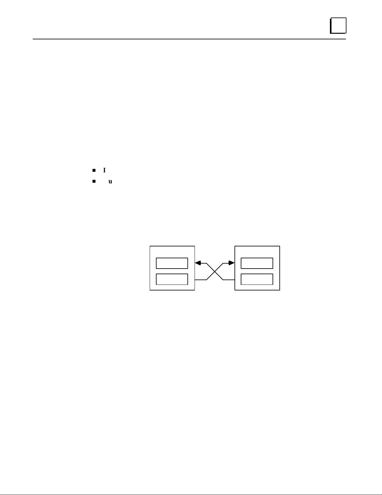
Input and Output Data
The master on an I/O Link can send 1024 outputs and receive up to 1024 inputs from
slave devices. A slave can send and receive either 32 or 64 inputs and outputs. For each
link device, inputs and outputs have the same meaning:
H
Input Data is data received from the link.
H
Output Data is data sent to the link.
So the same set of data is considered output data by the device that sends it and input
data by the device that receives it.
1
a45008
MASTER
INPUTS
OUTPUTS
For each Series 90–70 I/O Link Interface Module used as a master, %I and %Q
references and data lengths for each slave are assigned within the application Program
Block, using Logicmaster 90. Instructions for doing this are given in chapter 4. For other
types of devices on the link, references and data lengths are assigned differently. For
details on how a specific type of device handles its I/O Link data, you should refer to the
User’s Manual for that device.
SLAVE
INPUTS
OUTPUTS
9GFK–0644A Chapter 1 Introduction
Page 14

1
Data Sent by the Master
The master sends output data for all slave devices together. If a Series 90–70 PLC is the
master on an I/O Link, it simply places the data to be sent into the %Q output references
assigned to the I/O Link Interface Module.
Slaves receive the data in order of their positions on the link. Each slave in turn reads
out its configured amount of data, and passes the remainder on to the next slave. To a
slave, data received from the master is input data. If a Series 90–70 PLC is a slave, it
obtains the data received from the master by reading the %I input references assigned to
the I/O Link Interface Module.
a45009
MASTER
SLA VE
1
SLA VE
2
SLA VE
3
OUTPUTS 1
OUTPUTS
OUTPUTS
INPUTS
2
OUTPUTS
OUTPUTS
3
2
3
INPUTS
OUTPUTS
INPUTS
3
Data Returned by Slaves
The master continuously reads the output data from each slave. If a Series 90–70 PLC is
a slave, it provides this data by placing it into the %Q references configured for the I/O
Link Interface Module. If a Series 90–70 PLC is the master, it reads the data from the %I
references assigned to the I/O Link Interface Module.
a45004
MASTER
SLA VE
INPUTS
SLA VE
1
2
SLA VE
3
MASTER
SLA VE
1
OUTPUTS
SLA VE
2
SLA VE
The master identifies each set of data it receives with respect to the slave’s position on
the link. To the master, data received from slaves is input data.
10 Series 90t-70 I/O Link Interface Module User’s Manual – February 1993
3
GFK-0644A
Page 15

Inputs and Outputs Hold L ast State
The inputs and outputs of the I/O Link Interface Module will hold their last states if one of
the following events occurs:
H
the link is broken.
H
the master resets.
H
the slave resets.
H
the Series 90-70 PLC is put into STOP mode.
H
the Series 90-70 PLC is powered-down.
When the disruption is corrected, the module initializes all inputs and outputs to zero,
then quickly resets them to their actual states.
1
11GFK–0644A Chapter 1 Introduction
Page 16

1
Faults on the I/O Link
A. The Series 90–30 PLC, Series 90–70 PLC, and Power Mate CNC without a separate
encoder port handle faults as described below. The following information applies
only if there are no other types of devices on the link.
If one of the following faults occurs, communications stop at the fault location. If
there are prior devices on the link, they are still able to transfer data with the master.
If there are subsequent devices on the link, however, they cannot.
H
Power is removed from any device.
H
There is a fault in the I/O Link cable such as an open or shorted wire.
H
A module fault, software fault, or hardware fault occurs in the master or slave.
MASTER
DATA
SLA VE
1
POWER
REMOVED
HERE
SLA VE
2
a45010
SLA VE
3
If the master is a Series 90–70 PLC and one of the following faults occurs,
communications continue on the rest of the link.
H
A slave has been set up for the wrong amount of data.
H
A Series 90–30 slave is in Stop mode.
H
The sequence of slaves on the link is not the same as the sequence expected by
the master.
MASTER
SLAVE
1
PLACED
IN STOP
MODE
SLAVE
2
a45011
SLAVE
3
DATA
B. If the link is connected to any other type of device, including a Power Mate CNC
that has a separate encoder port, a fault on any device causes the entire link to shut
down as a safety precaution. If that happens, follow this procedure to restore link
operation.
1. Correct the condition that caused the fault.
2. With the master inactive on the link, clear system errors by power cycling each
CNC slave (turn power off, then on again).
3. Cycle power to each Series 90–30 I/O Link module, to clear the Logicmaster
fault table.
4. Reset the I/O link from the master .
12 Series 90t-70 I/O Link Interface Module User’s Manual – February 1993
GFK-0644A
Page 17

Diagnostics
The application Program Block automatically provides the Series 90–70 PLC with
diagnostic information about the I/O Link Interface Module, and about link operation if
the module is operating as a master. The diagnostic information is placed into %P
references assigned to that I/O Link Interface Module. Additional program logic can be
created to read these %P references for monitoring the following:
H
Whether an invalid configuration has been provided during link initialization. The
link will not operate until a valid configuration has been supplied.
H
Whether the I/O Link Module is operating properly .
H
Whether input data is being received.
H
Whether a link fault has occurred.
Chapter 4 e xplains how to add these diagnostics to an application program.
Link Control
In addition, the Program Block automatically reads other %P references in the Series
90–70 PLC to receive commands from the application program. These %P references
can be used to instruct the I/O Link Interface Module to do the following:
1
H
Operate as a master or a slave.
H
Disable or enable the input and/or output update between the master and slave(s).
H
Start or restart link operation.
H
Reset or stop link operation.
Use of these program references is also explained in chapter 4.
13GFK–0644A Chapter 1 Introduction
Page 18

1
Getting Star ted
To install and configure a Series 90–70 I/O Link Interface Module, follow these basic
steps:
1. Install the module and complete the I/O Link
2. Add the I/O Link Module to the Series 90–70 PLC Configuration
3. Select and install an application Program Block from the diskette
Follow the instructions in chapter 2 to install the Series 90–70 I/O Link Module.
After installing the other devices on the link (as instructed in their individual User’s
Manuals), complete the I/O Link cabling. This is also described in chapter 2.
Follow the instructions in chapter 3 to complete the Logicmaster 90 configuration
screen for an I/O Link Interface Module.
Chapter 4 explains how to choose the most appropriate Program Block from an
application diskette, and how to add it to a Program Folder.
4. Complete the program logic for the I/O Link Module
This is also explained in chapter 4.
14 Series 90t-70 I/O Link Interface Module User’s Manual – February 1993
GFK-0644A
Page 19

Chapter 2 Installation
section level 1 1
2
This chapter tells how to install an I/O Link Interface Module, and how to complete the
I/O Link that joins the module to other devices.
Installing the I/O Link Interface Module in the R ack
The I/O Link Interface Module must not be located to the left of any board that
generates interrupts (such as a PCM, Genius Bus Controller , Analog, GEnet LAN, or
Ethernet module).
figure bi level 1
table_big level 1
Caution
Rack power MUST be OFF when installing or removing the I/O Link
Module.
1. Grasp the module firmly with your hand and insert it into the card guide.
2. Align the module’s printed circuit board with the connector on the rack backplane
and slide it towards the connector until it has started to seat.
3. Place one thumb on the left side of the top plastic flange and the other thumb on the
left side of the bottom plastic flange. Push the board into the connector until the top
and bottom latches click onto the rack rails.
4. Visually inspect the board to be sure it has seated properly.
Caution
Make sure no exposed wiring touches any conductive material. Such
contact could damage the module, and other units to which it is
connected.
GFK-0644A
15
Page 20

2
5. A CPU module must be present in rack 0 slot 1 befor e applying power to the I/O Link
Interface Module. Turn on power, and observe the LEDs.
LED Name LED Status Indication
Module OK On The I/O Link Interface Module has passed its powerup
diagnostics and the hardware is operating properly .
OFF The module has failed a diagnostic test, or a run–time failure
has been detected.
Link Active On The module is communicating with the I/O Link.
OFF A failure has occurred with the I/O Link, and
communications are not possible.
Link Cfg ON I/O Link configuration has occurred, and the module is ready
to communicate.
OFF The module has not been configured for link operation.
Note
If a CPU is powered up for the first time after being received from the
factory (or for the first time after its configuration has been cleared or its
battery has been removed), and there is an I/O Link Interface Module
present in one of the racks of the PLC, a “Loss of Module” diagnostic is
generated in the PLC.
To proceed, clear the fault and download a configuration to the CPU.
See chapter 3 for configuration instructions. Once the CPU has been
configured, the “Loss of Module” diagnostic will only occur if the
module subsequently fails or is removed.
Removing the I/O Link Interface Module from the Rack
1. Remove power from the rack.
2. Squeeze the rack clips on the back of the cover to disengage the clips from the rack
rail.
3. Pull the module firmly to remove it from the backplane connector.
4. Slide the board along the card guide and remove it from the rack. A void contact with
neighboring boards and wiring.
16 Series 90t-70 I/O Link Interface Module User’s Manual – February 1993
GFK-0644A
Page 21

Connecting the I/O Link Interface Module to Other Devices
Using the appropriate cable, connect the devices on the I/O Link. Notice that the cables
are marked JD1A on one end and JD1B on the other.
Ports on the I/O Link Module
The functions of the ports on the I/O Link Interface Module depend on whether the
module is used as a master or as a slave.
2
Series 90-70
I/O Link
Interface Module
(as master)
JD1A
JD1B
Series 90-70
I/O Link
Interface Module
(as slave)
JD1B
not
used
JD1A
a45016
If the system also includes a Series 90–30 PLC, you will notice that the port functions for
the Series 90–30 I/O Link Interface Module are the same as the port functions on the
Series 90–70 I/O Link Interface Module when it is used as a slave.
I/O Link Module Used as a Master
If the module will be used as a master, connect the cable from the first slave to the upper
port. The lower port is not used in master mode.
JD1A
JD1B
a45017
JD1B
not
used
17GFK-0644A Chapter 2 Installation
Page 22

2
I/O Link Module Used as a Slave
If the module will be used as a slave, connect the cable from the previous device (either
the master or another slave) to the upper port. If the module is followed by another
slave on the link, connect the cable from that device to the lower port.
a45018
JD1A
Order of the Devices on the Link
The devices on an I/O Link must be installed in the order expected by the master . If the
Series 90–70 PLC is the master, be sure to connect the devices on a link in the order that
agrees with the information provided to the application Program Block.
Serial Port Pin Assignments
JD1B
JD1A
JD1B
Pin # Signal Pin # Signal
1 SIN 11 0 volts
2 *SIN 12 0 volts
3 SOUT 13 0 volts
4 *SOUT 14 0 volts
5 15 0 volts
6 16 0 volts
7 17
8 18 +5 volts
9 +5 volts 19
10 20 +5 volts
The +5–volt output from each connector powers the fiber optic link modules for long
distance applications. The +5–volt output is not used otherwise.
18 Series 90t-70 I/O Link Interface Module User’s Manual – February 1993
GFK-0644A
Page 23

Cable Diagram, No Optical Adapter
The following illustration shows connection details for electrical cable used between a
master and slave or between two slave devices. This cable (A03B–0807–K801,
A03B–0807–K802, or cable made using AMW 2076 and connectors A02B–0120–K301)
does not include the +5–volt signal. Optical Adapter cable, which includes the +5 volt
signal, must not be used to directly connect master and slave devices.
2
SIN
8SIN
SOUT
*SOUT
MASTER
01
02
03
04
05
06
07
08
09
10
OR
SLA VE
JD1A
0V
0V
0V
0V
JD1A
SOUT
*
SOUT
JD1B
01
(11)
(12)
(13)
(14)
SIN
02
SIN*
03
SOUT
04
SOUT*
05
06
07
08
09
10
JD1B
(3)
SOUT
(4)
SOUT*
(1)
SIN
(2)
SIN*
0V
0V
0V
0V
11
12
13
14
15
16
17
18
19
20
(1)
SIN
(2)
SIN
*
(3)
(4)
(11)
0V
(12)
0V
(13)
0V
(14)
0V
PCR–E20FS
11
12
13
14
15
16
17
18
19
20
SLA VE
a45019
0V
0V
0V
0V
The differential signals, SIN/*SIN, and SOUT/*SOUT must be connected using twisted
pair wires.
Caution
The I/O Link cable’s shield must be connected to chassis ground in
your system. Use the grounding cable (44A729227) provided.
19GFK-0644A Chapter 2 Installation
Page 24

2
Optical Adapter Installation
The Optical Adapter is an optional component used to interface the electrical cable to
optical cable.
An Optical Adapter must be installed in a sealed enclosure. Avoid contact with other
electrical components or wiring, which could short the unit. Use the adapter’s casing
screws to make earth ground connection. The electrical potential of the earth ground
used for the adapter must be the same as that of the I/O Link to which it is connected.
Cable Connections
Connection between two optical adapters is made using optical fiber cable
A66L–6001–009. Lengths of 10 to 100 meters are available. Connect the optical fiber
cable to COP1 on the adapter unit.
a45014
UNIT
JD1B
UNIT
JD1A
ELECTRICAL
CABLE
OPTICAL
I/O LINK
ADAPTOR
OPTICAL
JD1 COP1 COP1 JD1
CABLE
OPTICAL
I/O LINK
ADAPTOR
ELECTRICAL
CABLE
Connection between a master or slave device and an Optical Adapter is made using
electrical cable A03B–0807–K803, which is a one–meter cable with connectors on both
ends. Connect this cable to JD1 on the adapter. A connection diagram is shown below.
Cable Diagram, Electrical Cable to Optical Adapter
Cable A03B–0807–K803 provides the +5–volt signal required by the Optical Adapter.
Do not use this cable to directly connect master or slave devices; use it only with an
Optical Adapter .
a45020
UNIT SIDE
JD1A, JD1B
(01)
SIN
01
*
SIN
02
SOUT
03
SOUT
04
05
06
07
08
+5V
09
10
0V
11
0V
12
0V
13
*
0V
14
0V
15
0V
16
17
+5V
18
19
+5V
20
SIN
*SIN
SOUT
*SOUT
+%V
+5V
+5V
0V
0V
0V
0V
0V
0V
(02)
(03)
(04)
(09)
(18)
(20)
(11)
(12)
(13)
(14)
(15)
(16)
ADAPTER SIDE
JD1
SOUT
(03)
SOUT
(04)
SIN
(01)
SIN*
(02)
+5V
(09)
+5V
(18)
+5V
(20)
0V
(11)
0V
(12)
0V
(13)
0V
(14)
0V
(15)
0V
(16)
*
Note
The +5–volt output on the Series 90–70 I/O Link Module is fused with
a 0.5 Amp fuse. The fuse is not field replaceable.
20 Series 90t-70 I/O Link Interface Module User’s Manual – February 1993
GFK-0644A
Page 25

Chapter 3 Logicmaster 90-70 Configuration
section level 1 1
3
This chapter explains the Logicmaster 90–70 software configuration steps related to a
Series 90–70 I/O Link Interface Module. For the I/O Link Module, this configuration only
designates the location of the module; it does not assign I/O refer ences. After the module itself has
been “installed” using Logicmaster 90, you will set up and initialize the I/O Link as explained in
chapter 4.
Configuration Steps
1. In the LM90 configuration software, select I/O Configuration.
2. Display the configuration screen for the rack where the module will be located. The
Next Page and Prev Page keys are used to move between rack configuration screens.
3. In the correct rack display, move the reverse video cursor to the module’s intended
slot. (Use the left and right cursor keys to move the cursor).
figure bi level 1
table_big level 1
Note
DO NOT locate an I/O Link Interface Module to the left of any board that
generates interrupts (such as a PCM, Genius Bus Controller , Analog, GEnet
LAN, or Ethernet module).
GFK-0644A
21
Page 26

3
4. If you are using version 4 of Logicmaster, press F1 (vme) to display the catalog list
shown below. Select Foreign VME from the list.
If you are using version 3 of Logicmaster instead press F2 (vme) to display the
catalog list. From the list, select Foreign VME (no interrupt).
5. No further configuration is required; press Rack (Shift–F1) or the Escape key to
return to the rack display.
22 Series 90t-70 I/O Link Interface Module User’s Manual – February 1993
GFK-0644A
Page 27

Chapter 4 Programming Guide
section level 1 1
4
This chapter e xplains how to incorporate logic for one to four I/O Link Interface
Modules in an application program for the Series 90–70 PLC. Programming instructions
for other devices on the link are not included.
Overview
The Program Blocks on the diskettes provided with the I/O Link Interface Module will
transfer input and output data between the Series 90–70 PLC and up to four I/O Link
Interface Modules. The Program Blocks also monitor diagnostics from each I/O Link
Interface Module in the PLC, and provide a mechanism for controlling link operation
from the application program.
One Program Block is selected for the application, and added to the application program
using the Librarian function of Logicmaster 90–70.
figure bi level 1
table_big level 1
Logic must be added to the application program to call the Program Block, which will
execute once each time it is called. Normally, it is called once per PLC sweep.
The Program Block utilizes a range of %P references, set aside in PLC memory, to
exchange data with the Series 90–70 PLC. The application program interfaces with the
Program Block by reading and writing the same %P references. The Program Block also
makes use of a small group of %G references. These do not require any application
program interaction. However, it is important to be sure that these %G references are
not used for any other purpose.
GFK-0644A
23
Page 28

4
Selecting a Program Block
There are three Program Blocks on a diskette. Select the Program Block that provides
the level of functionality and performance required for the application.
Program Block
Identifier
LINK73X 1 512 points 731/732, 771/772, 781/782
LINK77X 2 2048 points 771/772, 781/782
LINK78X 4 4096 points 781/782
The LINK73X Program Block provides the fastest update speed and has the lowest
memory requirements, but is limited to a single I/O Link Interface Module per 90–70
system and 512 I/O points. LINK77X provides up to two I/O Link Interface Modules per
90–70 PLC and 2048 I/O points, but it is slightly slower and requires more memory .
LINK78X accommodates up to four I/O Link Interface Modules per PLC and provides
up to 4096 I/O points. Its update rate is slower than the other two Program Blocks, and
it uses more memory.
For the 731/732 CPU, the LINK73X P rogram Block is required. F or the 771/772 CPU,
either LINK73X or LINK77X can be used. For the 781/782 CPU, any of the three
Program Blocks can be used. Remember that the smaller Program Blocks will give better
performance.
Number of I/O
Link Modules
Maximum Number
of References
Compatible CPUs
Adding the Program Block Logic to an Application Program
To add a Program Block to an application program, follow these steps:
1. Copy the selected P rogram Block library file from the diskette to the Logicmaster
90–70 library directory (such as: c:\lm90\p70\p70_lib).
2. Using the Librarian function (available with Logicmaster 90–70 version 3.0 or later),
import the Program Block into the working folder.
3. If the application program will use nicknames for the Program Block %P references
(see page 27), include the nicknames in the Variable Declaration Table. The
nicknames are provided as three .SDE files in the program folder on the application
software diskette: LINK73SX.SDE, LINK77SX.SDE, and LINK78SX.SDE. To include
the appropriate file, go to the Variable Declarations in the working folder, select
“include”, and enter the path and filename (such as: c:\link\link73sx.sde).
4. Complete the application program logic as described on the following pages.
24 Series 90t-70 I/O Link Interface Module User’s Manual – February 1993
GFK-0644A
Page 29

Calling the Program Block
To call the LINKxxX block, place a Call instruction as close as possible to the start of the
main program. To assure consistent mapping of link I/O data, do not use permissive
logic to the call. Include at least one call to the LINKxxX block each program sweep, to
assure that the link status is routinely updated and the link retry mechanism is enabled.
This is discussed in more detail later in the chapter.
Example Call Instruction
In this example, the Call instruction calls Program Block LINK73X.
[ INTERRUPTS ]
[ START OF PROGRAM BLOCK ]
CALL LINK73X
4
Using Multiple Calls to the Program Block
For most applications, the main program will include only one Call instruction to the
LINKxxX Program Block. However, it is possible to use multiple calls in the program. For
example, a call might be used at a particular place in the program to update inputs, outputs,
or both. In this way, the Program Block call would serve as a “Do I/O” instruction.
In applications with long communications windows or in Constant Sweep Time mode, a
call to LINKxxX might be used at the beginning of the program to update only inputs,
with another call at the end to update only outputs.
When using multiple calls to the LINKxxX Program Block, all additional calls after the first
should use the set status of the “Link Active” status bit as a permissive to their ex ecution.
25GFK–0644 Chapter 4 Programming Guide
Page 30

4
Number of I/O Link Modules
Number of I/O Link Modules
(1–4)
Program (%P) References for the I/O Link Program Blocks
The I/O Link Program Blocks use the program registers (%P) shown below. The
references for devices 1 to 15 are used only if the I/O Link Module is a master, and it has
more than one slave.
Information in Reference Program Reference Nickname
%P0001 numlink
1st Module 2nd Module 3rd Module 4th Module
Rack location # (0–7)
Slot location # (2–9)
Status word (see page 32
Control word (see page 30
Device 0 (or I/O Link Module used as
slave), slave data length (32 or 64)
” slave start address of %I
” slave start address of %Q
Device 1, slave data length (32 or 64)
” slave start address of %I
” slave start address of %Q
Device 2, slave data length (32 or 64)
” slave start address of %I
” slave start address of %Q
Device 3, slave data length (32 or 64)
” slave start address of %I
” slave start address of %Q
Device 4, slave data length (32 or 64)
” slave start address of %I
” slave start address of %Q
Device 5, slave data length (32 or 64)
” slave start address of %I
” slave start address of %Q
Device 6, slave data length (32 or 64)
” slave start address of %I
” slave start address of %Q
Device 7, slave data length (32 or 64)
” slave start address of %I
” slave start address of %Q
Device 8, slave data length (32 or 64)
” slave start address of %I
” slave start address of %Q
Device 9, slave data length (32 or 64)
” slave start address of %I
” slave start address of %Q
Device 10, slave data length (32 or 64)
” slave start address of %I
” slave start address of %Q
Device 11, slave data length (32 or 64)
” slave start address of %I
” slave start address of %Q
Device 12, slave data length (32 or 64)
” slave start address of %I
” slave start address of %Q
Device 13, slave data length (32 or 64)
” slave start address of %I
” slave start address of %Q
Device 14, slave data length (32 or 64)
” slave start address of %I
” slave start address of %Q
Device 15, slave data length (32 or 64)
” slave start address of %I
” slave start address of %Q
.)
.)
Program
Ref.
%P0002
%P0003
%P0004
%P0005
%P0006
%P0007
%P0008
%P0009
%P0010
%P0011
%P0012
%P0013
%P0014
%P0015
%P0016
%P0017
%P0018
%P0019
%P0020
%P0021
%P0022
%P0023
%P0024
%P0025
%P0026
%P0027
%P0028
%P0029
%P0030
%P0031
%P0032
%P0033
%P0034
%P0035
%P0036
%P0037
%P0038
%P0039
%P0040
%P0041
%P0042
%P0043
%P0044
%P0045
%P0046
%P0047
%P0048
%P0049
%P0050
%P0051
%P0052
%P0053
Nickname
L1rack
L1slot
L1stat
L1cntrl
L1dev0
L1dev0I
L1dev0Q
L1dev1
L1dev1I
L1dev1Q
L1dev2
L1dev2I
L1dev2Q
L1dev3
L1dev3I
L1dev3Q
L1dev4
L1dev4I
L1dev4Q
L1dev5
L1dev5I
L1dev5Q
L1dev6
L1dev6I
L1dev6Q
L1dev7
L1dev7I
L1dev7Q
L1dev8
L1dev8I
L1dev8Q
L1dev9
L1dev9I
L1dev9Q
L1dev10
L1dv10I
L1dv10Q
L1dev11
L1dv11I
L1dv11Q
L1dev12
L1dv12I
L1dv12Q
L1dev13
L1dv13I
L1dv13Q
L1dev14
L1dv14I
L1dv14Q
L1dev15
L1dv15IL1d
v15Q
Program
Ref.
%P0054
%P0055
%P0056
%P0057
%P0058
%P0059
%P0060
%P0061
%P0062
%P0063
%P0064
%P0065
%P0066
%P0067
%P0068
%P0059
%P0070
%P0071
%P0072
%P0073
%P0074
%P0075
%P0076
%P0077
%P0078
%P0079
%P0080
%P0081
%P0082
%P0083
%P0084
%P0085
%P0086
%P0087
%P0088
%P0089
%P0090
%P0091
%P0092
%P0093
%P0094
%P0095
%P0095
%P0097
%P0098
%P0099
%P0100
%P0101
%P0102
%P0103
%P0104
%P0105
Nickname
L2rack
L2slot
L2stat
L2cntrl
L2dev0
L2dev0I
L2dev0Q.
L2dev1
L2dev1I
L2dev1Q
L2dev2
L2dev2
IL2dev2Q
L2dev3
L2dev3I
L2dev3Q
L2dev4
L2dev4I
L2dev4Q
L2dev5
L2dev5I
L2dev5Q
L2dev6
L2dev6I
L2dev6Q
L2dev7
L2dev7I
L2dev7Q
L2dev8
L2dev8I
L2dev8Q
L2dev9
L2dev9I
L2dev9Q
L2dev10
L2dv10I
L2dv10Q
L2dev11
L2dv11I
L2dv11Q
L2dev12
L2dv12I
L2dv12Q
L2dev13
L2dv13I
L2dv13Q
L2dev14
L2dv14I
L2dv14Q
L2dev15
L2dv15I
L2dv15Q
Program
Ref.
%P0106
%P0107
%P0108
%P0109
%P0110
%P0111
%P0112
%P0113
%P0114
%P0115
%P0116
%P0117
%P0118
%P0119
%P0120
%P0121
%P0122
%P0123
%P0124
%P0125
%P0126
%P0127
%P0128
%P0129
%P0130
%P0131
%P0132
%P0133
%P0134
%P0135
%P0136
%P0137
%P0138
%P0139
%P0140
%P0141
%P0142
%P0143
%P0144
%P0145
%P0146
%P0147
%P0148
%P0149
%P0150
%P0151
%P0152
%P0153
%P0154
%P0155
%P0156
%P0157
Nickname
L3rack
L3slot
L3stat
L3cntrl
L3dev0
L3dev0I
L3dev0Q
L3dev1
L3dev1I
L3dev1Q
L3dev2
L3dev2I
L3dev2Q
L3dev3
L3dev3I
L3dev3Q
L3dev4
L3dev4I
L3dev4Q
L3dev5
L3dev5I
L3dev5Q
L3dev6
L3dev6I
L3dev6Q
L3dev7
L3dev7I
L3dev7Q
L3dev8
L3dev8I
L3dev8Q
L3dev9
L3dev9I
L3dev9Q
L3dev10
L3dv10I
L3dv10Q
L3dev11
L3dv11I
L3dv11Q
L3dev12
L3dv12I
L3dv12Q
L3dev13
L3dv13I
L3dv13Q
L3dev14
L3dv14I
L3dv14Q
L3dev15
L3dv15I
L3dv15Q
Program
%P0158
%P0159
%P0160
%P0161
%P0162
%P0163
%P0164
%P0165
%P0166
%P0167
%P0168
%P0169
%P0170
%P0171
%P0172
%P0173
%P0174
%P0175
%P0176
%P0177
%P0178
%P0179
%P0180
%P0181
%P0182
%P0183
%P0184
%P0185
%P0186
%P0187
%P0188
%P0189
%P0190
%P0191
%P0192
%P0193
%P0194
%P0195
%P0196
%P0197
%P0198
%P0199
%P0200
%P0201
%P0202
%P0203
%P0204%
P0205
%P0206
%P0207
%P0208
%P0209
Ref.
Nickname
L4rack
L4slot
L4stat
L4cntrl
L4dev0
L4dev0I
L4dev0Q
L4dev1
L4dev1I
L4dev1Q
L4dev2
L4dev2I
L4dev2Q
L4dev3
L4dev3I
L4dev3Q
L4dev4
L4dev4I
L4dev4Q
L4dev5
L4dev5I
L4dev5Q
L4dev6
L4dev6I
L4dev6Q
L4dev7
L4dev7I
L4dev7Q
L4dev8
L4dev8I
L4dev8Q
L4dev9
L4dev9I
L4dev9Q
L4dev10
L4dv10I
L4dv10Q
L4dev11
L4dv11I
L4dv11Q
L4dev12
L4dv12I
L4dv12Q
L4dev13
L4dv13I
L4dv13Q
L14ev14
L4dv14I
L4dv14Q
L4dev15
L4dv15I
L4dv15Q
26 Series 90t-70 I/O Link Interface Module User’s Manual – February 1993
GFK-0644A
Page 31

Using Nicknames for the %P References
If you want to use the %P nicknames listed in the table, add them to the Variable
Declaration Table (see page 24).
Global (%G) References for the I/O Link Program Blocks
The %P references listed in the previous table are used for link configuration, control,
and monitoring. They will be included in the application program as explained on
subsequent pages.
An I/O Link Program Block also uses certain %G references for its own operations.
These %G references should not be included in the application program. They should be
reserved for the ex clusive use of the Program Block.
Program Block Identifier %G References to be
Reserved
LINK73X %G1025 – %G1040
4
LINK77X %G1025 – %G1040
%GA1025 – %GA1040
%GB1025 – %GB1040
LINK78X %G1025 – %G1040
%GA1025 – %GA1040
%GB1025 – %GB1040
%GC1025 – %GC1040
%GD1025 – %GD1040
27GFK–0644 Chapter 4 Programming Guide
Page 32

4
Configuring I/O Links
In the application program, use Move and Block Move instructions to configure the I/O
Links in the system by placing the required data in the appropriate %P program
references.
Configuration Logic, Example
Use Move instructions to supply the number of I/O Link Interface Modules (1), and the
rack location (0), and slot location (5) of that module.
| +–––––+ +–––––+ +–––––+
+––––––––+MOVE_+–––––––––––––––––+MOVE_+–––––––––––––––––+MOVE_+–
| | INT | | INT | | INT |
| | | NUMLINK | | L1RACK | | L1SLOT
| CONST –+IN Q+–%P00001 CONST –+IN Q+–%P00002 CONST –+IN Q+–%P00003
| +00001 | LEN | +00000 | LEN | +00005 | LEN |
| |00001| |00001| |00001|
| +–––––+ +–––––+ +–––––+
|
Block Move instructions can supply the data lengths and beginning %I and %Q
addresses for six slaves on the link, which is link 1 in this example.
| +–––––+ +–––––+ +–––––+
+––––––––+BLKMV+–––––––––––––––––+BLKMV+–––––––––––––––––+BLKMV+–
| | INT | | INT | | INT |
| | | L1DEV0 | | L1DEV2 | | L1DEV4
| CONST –+IN1 Q+–%P00006 CONST –+IN1 Q+–%P00012 CONST –+IN1 Q+–%P00018
| +00032 | LEN | +00032 | LEN | +00032 | LEN |
| |00001| |00001| |00001|
| | | | | | |
| CONST –+IN2 | CONST –+IN2 | CONST –+IN2 |
| +00001 | | +00097 | | +00151 | |
| | | | | | |
| CONST –+IN3 | CONST –+IN3 | CONST –+IN3 |
| +00001 | | +00097 | | +00151 | |
| | | | | | |
| CONST –+IN4 | CONST –+IN4 | CONST –+IN4 |
| +00064 | | +00032 | | +00064 | |
| | | | | | |
| CONST –+IN5 | CONST –+IN5 | CONST –+IN5 |
| +00033 | | +00129 | | +00215 | |
| | | | | | |
| CONST –+IN6 | CONST –+IN6 | CONST –+IN6 |
| +00033 | | +00129 | | +00215 | |
| | | | | | |
| CONST –+IN7 | CONST –+IN7 | CONST –+IN7 |
| +00000 | | +00000 | | +00000 | |
| +–––––+ +–––––+ +–––––+
The first Block Move configures the length and beginning %I and %Q addresses of
devices 0 and 1. The second Block Move configures devices 2 and 3. The third Block
Move configures devices 4 and 5. T o simplify programming, IN7 in these Block Moves is
not used. If there were more I/O Links, or more devices on link 1, they would be
configured in the same manner.
28 Series 90t-70 I/O Link Interface Module User’s Manual – February 1993
GFK-0644A
Page 33

Configuration Guidelines
To configure the I/O Link(s) in a PLC system, enter constant data values into the
appropriate %P registers. These values determine:
H
The number of I/O Link Interface Modules in the PLC.
H
The rack and slot location of each I/O Link Interface Module.
H
The data length for each slave device (32 or 64 for a Power Mate).
H
The beginning address in PLC %I memory for input data.
H
The beginning address in PLC %Q memory for output data.
This must be done before the start command is issued to any I/O Link Interface Module
(as explained later in this chapter).
Program references for the I/O Link P rogram Blocks are listed in the table opposite.
Specify the Number of I/O Link Modules
The total number of modules specified in %P must be compatible with the Program
Block being used:
A. for LINK73X, %P00001 must be 1
B. for LINK77X, %P00001 may be 1 or 2
4
C. for LINK78X, %P00001 may be 1 to 4
Configuring the I/O Link Module as a Master
If the I/O Link Interface Module is a master, specify a data length and references for each
slave on the I/O Link. The data length (I/O count) for each device must be 0, 32, or 64.
No other values are correct.
The starting %I and %Q addresses must be compatible with the Program Block being used:
A. for LINK73X, the range is (1 to 481) or (1 to 449)
B. for LINK77X, the range is (1 to 2017) or (1 to 1985)
C. for LINK78X, the range is (1 to 4065) or (1 to 4033)
Configure all devices to have consecutive numbers; do not leave any “holes” in the
configuration for a module. If a 0 is configured for a slave’s data length, the data lengths
of all subsequent slaves on the same link must also be 0.
Note
All %P references from %P0009 through %P0209 which are not used for the
application must be set to 0 before the link is activated.
Configure all %I and %Q starting addresses at word boundaries.
Configuring the I/O Link Module as a Slave
If the module is a slave, configure it to be Device 0. Specify its data length (32 or 64) and
references.
Assign a starting %I and %Q address for the module that is compatible with the
Program Block being used. The %I and %Q addresses must begin on word boundaries.
Set to 0 the unused %P references for devices 1 through 15. See “Configuring the I/O
Link Module as a Master”, above.
29GFK–0644 Chapter 4 Programming Guide
Page 34

4
Controlling the I/O Link Module
Operation of the module is controlled by setting or clearing bits in the control word,
which is located at:
H
%P00005 for link 1
H
%P00057 for link 2
H
%P00109 for link 3
H
%P00161 for link 4
The bits in the control word for each I/O Link Interface Module contain the following
information:
MSB
16 15 14 13 12 1 1 10 9
These are one–shot commands. Do not repeatedly write to these bits––that would
unnecessarily increase program PLC sweep time and cause unexpected link results.
Set Master or Slave Mode (bit 16)
Set the most significant bit of the control word as part of the configuration routine that
loads all of the other %P registers with the correct values. To use the module as a master,
set this bit to 1. To use the module as a slave, set it to 0.
Start/Restart (bit 15)
unlabelled bits not used
Disable output update = 1
Disable input scan = 1
reserved (must be 0)
Reset/stop link = 1
Start link = 1
Master = 1
Slave=0
LSB
87654321
Always set to 0
After loading a valid configuration into the appropriate %P registers, write a 1 into
control bit 15 using a one–shot permissive. The module confir ms receipt of the start
command by resetting this bit to a 0.
If the module is being used as a master, setting this bit to 1 starts the module and the
link. It can also be used to restart the link after a link reset has occurred.
If the module is being used as a slave, use this bit to start or restart the module itself (not
the link).
Reset or Stop (bit 13)
To stop or reset the module, write a 1 to control bit 13, using a one–shot permissive. The
module confirms receipt of the command by resetting bit 13 to a 0. The status shows
Error Code 6, indicating that a reset was issued and the fault bit was not set.
30 Series 90t-70 I/O Link Interface Module User’s Manual – February 1993
GFK-0644A
Page 35

If the module is a master, this bit resets or stops both the module and the I/O Link. If
the module is a slave, setting this bit to 1 resets or stops only the module itself, not the
I/O Link.
Disable or Enable the Input Update (bit 10)
To disable the input update portion of the I/O scan, write a 1 to control bit 10. This might
be done during program debugging, or if the program uses multiple calls to the
LINKxxX Program Block. Disabling the input update causes the module to ignore new
inputs it receives. To re–enable input updates, clear control bit 10 by writing a 0 to it.
Remember that input data is considered to be output data by the device that sends it
(see page 26 for an explanation of input and output data).
If the module is a master, setting this bit to 1 causes all input references assigned to
devices on the link to hold their last states. The slaves continue to send data to the
master, but the new data is ignored by the master; no data is written to the input table.
If the module is a slave, setting this bit to 1 causes the input references assigned to the
module to hold their last states. The master continues to send data to the slave, but the
new data is ignored by the slave. No data is written to the input table.
4
Disable or Enable the Output Update (bit 9)
Disabling the output update keeps the module from updating outputs; it does not keep
the module from sending them. If outputs are disabled, the module keeps sending its last
set of output data repeatedly . This might be desirable during program debugging, or if
the program uses multiple calls to the Program Block.
Remember that output data is considered to be input data by the device that receives it.
To disable the output update, write a 1 to control bit 9. To re–enable output updates,
clear control bit 9 by writing a 0 to it.
If the module is a master, disabling the output update means that no new data will be
sent to any slaves on the link. They will continue to receive the same set of data from
the master repeatedly.
If the module is a slave, disabling the output update means that no new data will be sent
to the master. It will continue to receive the same set of data from that specific slave
repeatedly.
31GFK–0644 Chapter 4 Programming Guide
Page 36

4
Monitoring Link Operation
For each link, the Program Block uses a specific program register (%P) for status data.
These are:
H
%P00004 for link 1
H
%P00056 for link 2
H
%P00108 for link 3
H
%P00160 for link 4
Monitor the status word for information about:
A. the operation of the inter face module
B. the operation of the link
C. detailed error codes to help diagnose problems
Bits in the status word for an I/O Link contain the following information:
MSB
16 15 14 13 12 1 1 10 9
Bits 9 to 12 of the status word are reserved; they should be zeros.
Monitor the Module (bit 16)
This bit shows the status of module operation, and of link operation if the module is a
master . The application program should monitor this bit. If it is 0, the program should
take appropriate action such as ignoring any I/O or status information from the module.
The Program Block automatically sets bit 16 to 1 when the module passes its powerup
diagnostics, the correct rack and slot are placed in the %P configuration registers, and
VME backplane communications have been established.
The Program Block resets bit 16 to 0 if a module hardware fault is detected, or backplane
communications are interrupted.
unlabelled bits not used
reserved
Fault active = 1
Link failed = 1
Link active = 1
Board OK = 1
LSB
87654321
Error code
Pressing the I/O Link Interface Module’s Reset pushbutton does not clear this bit. The
Program Block will only try to reinitialize the module after completing powerup
diagnostics. An automatic r etry will occur only after link faults; the user must restart the link
after a hardware r eset.
Monitor Communications Status (bit 15)
Monitor status bit 15 to check the status of communications on the link. If this bit is a 0,
input data is NOT being received, and appropriate action should be taken. The Program
32 Series 90t-70 I/O Link Interface Module User’s Manual – February 1993
GFK-0644A
Page 37

Block automatically sets this bit to 1 shortly after the application program sets control bit
15 (start bit) to a 1.
If the module is a master, bit 15 is 1 if all link devices are providing input data and are
ready to receive output data. The Program Block automatically resets this bit to a 0 if any
link fault occurs.
If the module is a slave, bit 15 is 1 if the module is ready to exchange data with the
master .
Monitor for Link Failure (bit 14)
If the module is a master, after a link fault occurs, and the specified number of retries
have failed, the Program Block sets this bit to a 1. It is necessary to manually intervene
to find the cause of the failure. Look at the error code in the least significant byte of the
status word. Error codes are listed in the next table.
After the problem is corrected, reinitialize and restart the link. The Program Block
automatically clears status bit 13 when a restart is attempted.
4
Monitor for an Invalid Configuration or Link Fault (bit 13)
The application program should monitor this bit to verify operation of the I/O Link.
If status bit 13 is a 1, either an invalid configuration was provided during link
initialization, or a fault has occurred on an active link. The Program Block sets this bit to
a 1 immediately after the problem occurs.
If the problem occurs during initialization, initialization stops. It will be necessary to
enter a valid configuration into the %P registers before initialization can continue. The
error code in the least significant byte of the status word will indicate what the
configuration problem is.
If the module is a master and the problem is an active link fault, the Program Block
automatically tries to restart the link the specified number of times.
The Program Block automatically clears this bit when the link becomes active again. If
this bit continually cycles on and off, the link wiring and devices should be inspected. The
application program can keep track of the number of link faults over time, and take appropriate
action if too many faults occur .
33GFK–0644 Chapter 4 Programming Guide
Page 38

4
Error Codes: Troubleshooting
The less significant byte of an I/O Link status register contains an error code supplied by
the Program Block. Error codes are listed below and on the next page.
Error
Code
0 No error None
1 I/O Link module
2 External I/O link
3 Configuration error T ry to reinitialize the link interface. If the problem persists, contact the GE
4 Link interface is not
6 Link Reset This code indicates that a reset has occurred, or that the application program
Description of
Error
hardware fault
failure
responding
Recommended Action
Reset the module by pressing the pushbutton or cycling power . If the
problem persists, replace the module.
This fault can be caused by pressing the Reset pushbutton while the link is
operating. If that is not the cause, inspect all cabling and examine carefully
each link device. Reset the link. If the problem persists, remove devices
from the link one at a time to isolate the defective unit. This error code may
also be caused by a hardware problem on the I/O Link Interface Module.
Fanuc PLC ser vice hotline (phone number: 1–800–978–5747).
Check that the I/O Link Interface Module is installed in the rack and slot
location specified in the %P configuration data. Also determine if the
module is inserted completely in the backplane, and the VME bus is
operating to other modules in that rack. Make sure that the Logicmaster
configuration has been correctly completed for the module as described in
chapter 4. Reset the module by cycling power on the rack. If the problem
persists, replace the link module.
has reset the link by writing a 1 to control bit 13. The fault bit (status bit 12)
is not set. The I/O Link Module automatically resets control bit 13 to 0 to
acknowledge that it has received the command.
9 Invalid Number of
I/O Link Modules
This code means that the number of I/O Link Interface Modules is not in the
range of 0–2 or 0–4, as specified in program reference %P0001.
34 Series 90t-70 I/O Link Interface Module User’s Manual – February 1993
GFK-0644A
Page 39

Configuration Error Codes
Error Codes 10 to 91, listed below, describe configuration errors. If the I/O Interface
Module is being used as a slave, only Error Codes 10, 11, 12, 28, and 44 are used.
4
Error
Code
Description of Error Recommended Action Error
10 Invalid rack ID Must be in range 0–7 44
11 Invalid slot ID Must be in range 2–9 60 Link devices not de-
12
Dev . 0, Invalid data
length
13
Dev. 1 ”
14
Dev. 2 ”
15
Dev. 3 ”
16
Dev. 4 ”
17
Dev. 5 ”
18
Dev. 6 ”
19
Dev. 7 ”
20
Dev. 8 ”
21
Dev. 9 ”
22
Dev. 10 ”
23
Dev. 11 ”
24
Dev. 12 ”
25
Dev. 13 ”
26
Dev. 14 ”
27
Dev. 15 ”
28
Dev . 0, invalid %I
starting address
29
Dev. 1 ”
30
Dev. 2 ”
31
Dev. 3 ”
32
Dev. 4 ”
33
Dev. 5 ”
34
Dev. 6 ”
35
Dev. 7 ”
36
Dev. 8 ”
37
Dev. 9 ”
38
Dev. 10 ”
39
Dev. 11 ”
40
Dev. 12 ”
41
Dev. 13 ”
42
Dev. 14 ”
43
Dev. 15 ”
Must be 0, 32, or 64. 61
Must not be greater
than maximum I/O data
length.
Code
Description of Error Recommended Action
Dev. 0, invalid %Q
starting address
45
Dev. 1 ”
46
Dev. 2 ”
47
Dev. 3 ”
48
Dev. 4 ”
49
Dev. 5 ”
50
Dev. 6 ”
51
Dev. 7 ”
52
Dev. 8 ”
53
Dev. 9 ”
54
Dev. 10 ”
55
Dev. 11 ”
56
Dev. 12 ”
57
Dev. 13 ”
58
Dev. 14 ”
59
Dev. 15 ”
fined with consecutive addresses
Dev . 0, configured
but not responding.
62
Dev. 1 ”
63
Dev. 2 ”
64
Dev. 3 ”
65
Dev. 4 ”
66
Dev. 5 ”
67
Dev. 6 ”
68
Dev. 7 ”
69
Dev. 8 ”
70
Dev. 9 ”
71
Dev. 10 ”
72
Dev. 11 ”
73
Dev. 12 ”
74
Dev. 13 ”
75
Dev. 14 ”
76
Dev. 15 ”
77
1 extra (undefined)
device on the link
2 extra (undefined)
78
devices on the link
3 ”
79
4 ”
80
5 ”
81
6 ”
82
7 ”
83
8 ”
84
9 ”
85
10 ”
86
11 ”
87
12 ”
88
13 ”
89
14 ”
90
15 ”
91
Must not be greater
than maximum I/O data
length.
All data length register
values must be 0, following the first occurrence of 0.
Link doesn’t operate.
Link continues to oper-
ate with dev . 0
Link continues to oper-
ate with previous devices.
”
”
”
”
”
”
”
”
”
”
”
35GFK–0644 Chapter 4 Programming Guide
Page 40

Index
A
Active Link fault, 33
A ddress Assignment, 29
Application software, 3 , 23
B
Board OK bit, 32
C
Cable diagrams, 19 , 20
Cable lengths, 7
Cables and connectors, 6
Calling the Program Block, 24
Catalog Number
Grounding Cable, 19
Optical Adapter , 6
Chassis ground, 19
Communications window time, 24
Configuration error, 34
Configuration example, 28
Configuration, invalid, 33
Configuration, Series 90 PLC, 21
Connectors, 4
Device numbers, 26
Diagnostics, 13
Dimensions, 5
Disable I/O update bits, 30
Distance between devices, 7
Do I/O , 24
E
Electromagnetic noise, 8
Error code bits, 32
Error code definitions, 34 , 35
Example logic, 25 , 28
F
Fanuc I/O Link, 1
Fault Active bit, 32
Faults on I/O Link, 12
G
Getting started, 14
Global (%G) references used, 27
Grounding cable, 19
36
Constant Sweep Time CPU mode, 24
Control bit definitions, 30
Control the link, 3
Control word, 26 , 30
Controlling the I/O Link Module, 30
CPU module, 15
CPUs, compatible, 23
Current requirement, 5
D
Data length, 3
Data lengths, 26 , 29
Data transmission rate, 5
H
Hardware fault error, 34
Hotline phone number, 34
Humidity specification, 5
I
I/O capacity, 1
I/O Link Modules, number of, 3
I/O Links, number of, 23
I/O update, enable/disable bits, 30
Input data, 9 , 10
Inputs, enable/disable, bit, 30 , 31
Installation, 15
GFK-0644A
Page 41

Index
Installation, I/O Link Module, 15
Installation, Optical Adapter , 20
Interrupts, 21
L
LEDs, 4 , 15
Link Active bit, 24 , 32
Link Active LED, 4 , 15
Link Cfg LED, 15
Link control, 13
Link Failed bit, 32
Link failure error , 34
Link operation stops, 12
LINK73X, links and I/O, 23
LINK77X, links and I/O, 23
LINK78X, links and I/O, 23
Logic examples, 25 , 28
Logicmaster 90–70, 21
Logicmaster 90–70 librarian, 24
M
Master devices, 1
Master/slave mode bit, 30
Module appearance, 4
Module installation, 15
Module OK LED, 4 , 15
Module removal, 16
Module type, 5
Monitoring the link, 32
Monitoring the module, 32
Multiple calls, 24
N
Nicknames for %P references, 24 , 26
Normal operation, 34
Number of I/O Link Modules, 1
Number of modules, 29
O
Optical Adapter, 8 , 20
Output data, 9 , 10
Output, +5 volt, 18 , 20
Outputs, enable/disable bit, 30
P
P ermissive logic, 30
Pin assignments, 18
P orts, 4
Program Block installation, 24
Program Blocks, 3 , 23
Program nicknames, 26
Program references, 26
Programming, 23
R
Rack location, 3 , 4 , 21 , 26 , 29
Reference addresses, 3
Reference assignment, 29
References, 9
References, maximum, 23
Removal, 16
Reset pushbutton, 4
Reset/Stop link bit, 30
S
Serial port pin assignments, 18
Signal levels, 9
Slave devices, 1
Slot location, 3 , 4 , 26 , 29
Specifications, 5
Start Link bit, 30
Status bit definition, 32
Status word, 26 , 32
Stop Link bit, 30
System overview, 1
GFK-0644A
37
Page 42

Index
T
Temperature specification, 5
Troubleshooting, 34
V
Vibration and shock specification, 5
38
GFK-0644A
 Loading...