

GE ADW1000K00BB, EDW2050F02CC, EDW3060G02SS, EDW3060G03SS, GSD1900J01WH Installation Guide
...Page 1
Ifyouhaveaquestionconcerningtheinstallationofthis
product,calltheGEAnswerCenter<R_ConsumerInformation
Serviceat800.626.2000,24hoursaday,7daysaweek.
Ifyoureceivedadamageddishwasher,
youshouldimmediatelycontactyour
dealerorbuilder.
[] Two Phillips head countertop mounting screws taped to dishwasher
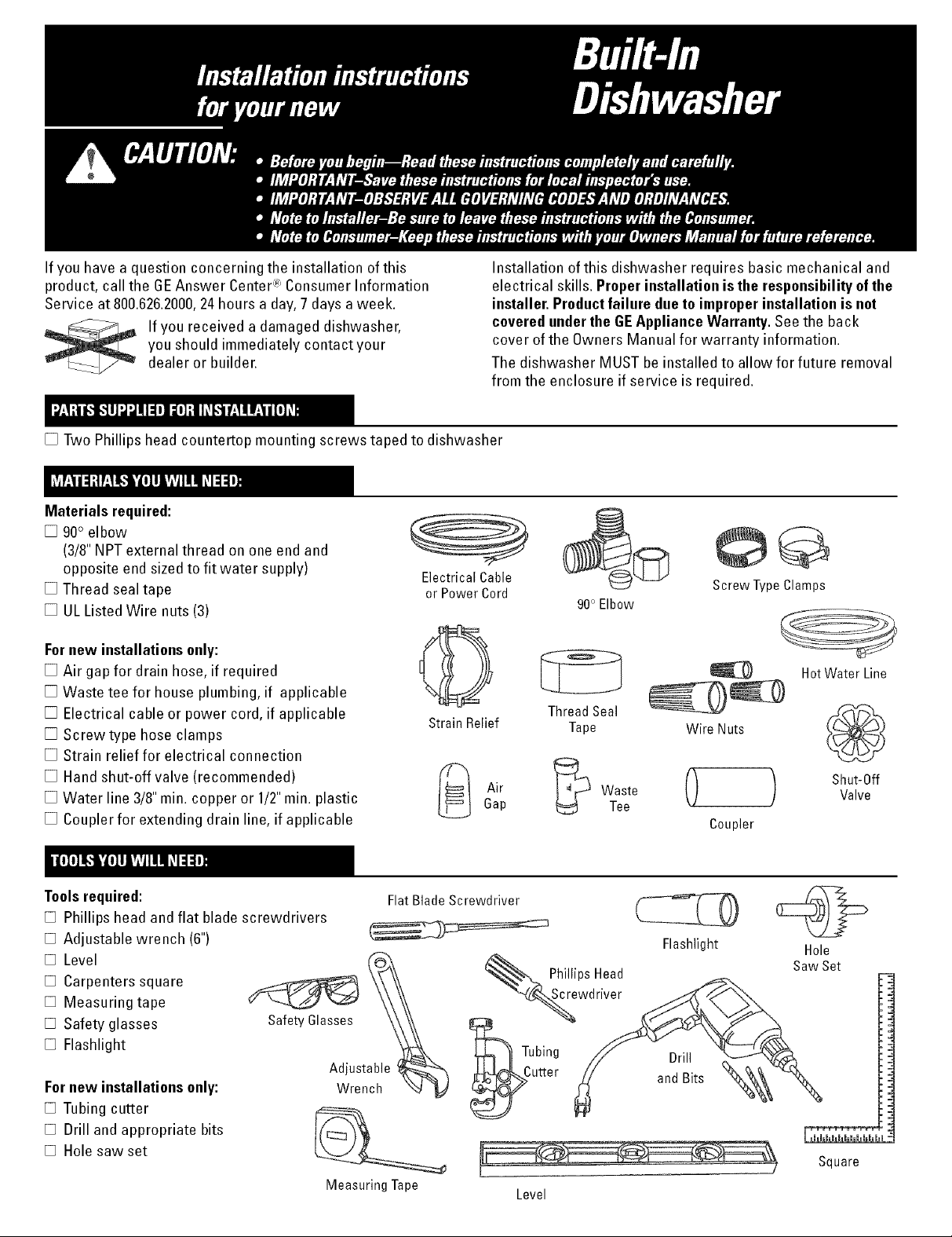
Materials required:
[] 90° elbow
(3/8"NPT external thread on one end and
opposite end sized to fit water supply)
[] Thread seal tape
[] UL Listed Wire nuts (3)
Fornew installations only:
[] Air gap for drain hose, if required
[] Waste tee for house plumbing, if applicable
[] Electrical cable or power cord, ifapplicable
[] Screwtype hose clamps
[] Strain relief for electrical connection
[] Hand shut-off valve (recommended)
[] Water line 3/8"min. copper or 1/2"min. plastic
[] Coupler for extending drain line, ifapplicable
Electrical Cable
or Power Cord
StrainRelief Tape
A,r Waste() )
Gap Tee
Installationofthisdishwasherrequiresbasicmechanicaland
electricalskills.Properinstallation is the responsibilityof the
installer. Productfailure dueto improperinstallation is not
coveredunderthe GEAppliance Warranty.See the back
cover of the Owners Manual for warranty information.
The dishwasher MUST beinstalledto allow for future removal
from the enclosure if service isrequired.
Screw Type Clamps
HotWaterLine
ThreadSeal
Wire Nuts
Shut-Off
Valve
Coupler
Toolsrequired:
[] Phillips head and flat blade screwdrivers
[] Adjustable wrench (6")
[] Level
[] Carpenters square
[] Measuring tape
[] Safety glasses
[] Flashlight
Fornew installations only:
[] Tubing cutter
[] Drill and appropriate bits
[] Holesaw set
SafetyGlasses
FlatBlade Screwdriver
Adjustable
Wrench
Measuring Tape
Flashlight Hole
Saw Set
__Sc rePhillipsHead
wdri_
_Tubing // Drill
_Cutter _/ andBits _-_
Square
Level
Page 2
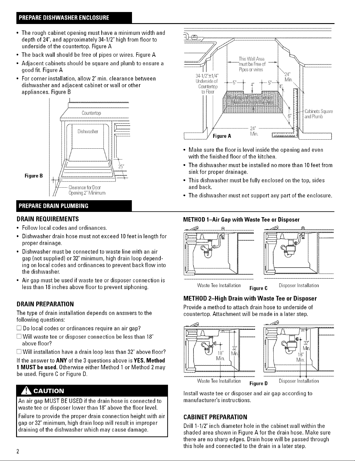
• The rough cabinet opening must have a minimum width and
depth of 24",and approximately 34-1/2"high from floor to
underside of the countertop. Figure A
• The backwall should be free of pipes or wires. Figure A
• Adjacent cabinets should be square and plumbto ensure a
good fit. Figure A
• For corner installation, allow 2" min. clearance between
dishwasher and adjacent cabinet or wall or other
appliances. Figure B
This'v%ll Area
)[
Ppesorwires
34--1/2":_1/4"
UndersideoF
Countertop
to%or
Countertop
E
Dishwasher _\l
25"
FigureB
Clearancefor Door
Openi_g2" Min}mum
DRAIN REQUIREMENTS
• Follow local codes and ordinances.
• Dishwasher drain hose must not exceed 10feet in length for
proper drainage.
• Dishwasher must be connected to waste line with an air
gap (not supplied) or 32" minimum, high drain loop depend-
ing on local codes and ordinances to prevent backflow into
the dishwasher.
• Air gapmust be used if waste tee or disposer connection is
less than 18inches above floor to prevent siphoning.
Cab}_etsSquae
a_dPlumb
• Make sure the floor is level inside the opening and even
with the finished floor of the kitchen.
• The dishwasher must be installed no more than 10feet from
sink for proper drainage.
• This dishwasher must befully enclosed onthe top, sides
and back.
• The dishwasher must not support any part of the enclosure.
METHOD1-Air Gapwith Waste Teeor Disposer
WasteTeeInstallation
FigureC
DisposerInstallation
DRAIN PREPARATION
The type of drain installation depends onanswers to the
following questions:
[] Do local codes or ordinances require an air gap?
[] Will waste tee or disposer connection be less than 18"
abovefloor?
[] Will installation have a drain loop lessthan 32"above floor?
If the answer to ANY of the 3 questions above is YES, Method
1 MUST be used. Otherwise either Method 1 or Method 2 may
be used. Figure C or Figure D.
An air gap MUST BE USEDif the drain hose is connected to
waste tee or disposer lower than 18"above the floor level.
Failure to provide the proper drain connection height with air
gap or 32"minimum, high drain loop will result in improper
dra n ng of the d shwasher wh ch may cause damage.
METHOD 2-High Drain with Waste Tee or Disposer
Providea method to attach drain hose to underside of
countertop. Attachment will be made in a later step.
g:--
Waste Tee Installation Figure D
Install waste tee or disposer and air gap according to
manufacturer's instructions.
CABINET PREPARATION
Drill 1-1/2"inch diameter hole in the cabinet wall within the
shaded area shown in Figure A for the drain hose. Make sure
there are no sharp edges. Drain hose will be passedthrough
this hole and connected to the drain in a later step.
DisposerInstallation
Page 3
WARNING
FORPERSONALSAFETY:REMOVEHOUSE
FUSEOROPEN CIRCUITBREAKERBEFORE
BEGINNINGINSTALLATION.
DONOTUSEAN EXTENSIONCORDDRADAPTER PLUG
WITH THIS APPLIANCE.
ELECTRICALREQUIREMENTS:
• This appliance must be supplied with 120V,60 Hz.,and
connected to an individual, properly grounded branch
circuit, protected by a 15or 20ampere circuit breaker or
time delay fuse.
• Wiring must be 2wire with ground.
• Ifthe electrical supply provided does not meet the
above requirements, call a licensed electrician before
proceeding.
GROUNDING INSTRUCTION
This appliance must be connected to a grounded metal,
permanent wiring system, or an equipment-grounding conduc-
tor must be run with the circuit conductors and be connected
to the equipment-grounding terminal orlead on the appliance.
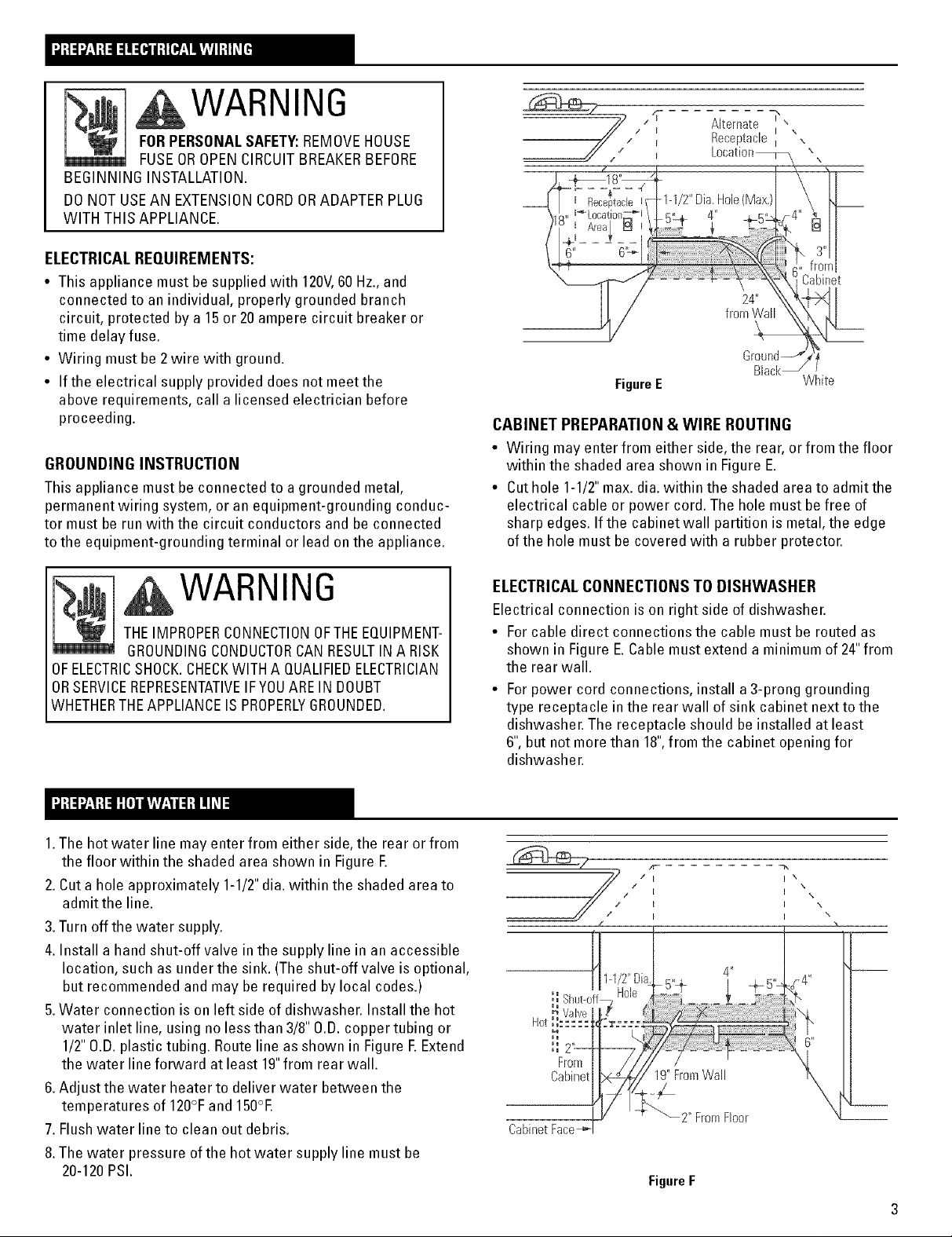
-1-1/2"Dia.Flole(Max,)
FigureE
CABINET PREPARATION & WIRE ROUTING
• Wiring may enter from either side, the rear, or from the floor
within the shaded area shown in Figure E.
• Cuthole 1-1/2"max. dia.within the shaded area to admit the
electrical cable or power cord. The hole must be free of
sharp edges. If the cabinet wall partition is metal,the edge
ofthe hole must be covered with a rubber protector.
4"
Cabinet
Black_"
White
WARNING
THEIMPROPERCONNECTIONOFTHEEQUIPMENT-
GROUNDINGCONDUCTORCAN RESULTINA RISK
OFELECTRICSHOCK.CHECKWITH A QUALIFIEDELECTRICIAN
ORSERVICEREPRESENTATIVEIFYOUAREINDOUBT
WHETHERTHEAPPLIANCEIS PROPERLYGROUNDED.
1.The hot water line may enter from either side, the rear or from
the floor within the shaded area shown in Figure E
2.Cut a hole approximately 1-1/2"dia. within the shaded area to
admit the line.
3.Turn off the water supply.
4. Install a hand shut-off valve in the supply line in anaccessible
location, such as under the sink. (The shut-off valve is optional,
but recommended and may be required by local codes.)
5.Water connection is on left side of dishwasher. Install the hot
water inlet line, using no less than 3/8" O.D.copper tubing or
1/2"O.D.plastic tubing. Route line as shown in Figure E Extend
the water line forward at least 19"from rear wall.
6.Adjust the water heater to deliver water between the
temperatures of 120°Fand 150°E
7. Flushwater line to clean out debris.
8.The water pressure of the hot water supply line must be
20-120PSI.
ELECTRICALCONNECTIONS TO DISHWASHER
Electrical connection is on right side of dishwasher.
• Forcable direct connections the cable must be routed as
shown in Figure E.Cable must extend a minimum of 24"from
the rear wall.
• Forpower cord connections, install a3-prong grounding
type receptacle in the rear wall of sink cabinet next to the
dishwasher. The receptacle should be installed at least
6", but not more than 18",from the cabinet opening for
dishwasher.
Cabinet Face
2" FromFloor
FigureF
Page 4

If you need help with any of the following steps, call the
GEAnswer Center':R_Consumer Information Service, 800.626.2000
Do not remove the wood base until you are ready to install
the dishwasher. The dishwasher will tip over when the door
is opened.
Step1checkdoorbalancebeforewoodbaseisremoved
Locate the 2 Phillips head countertop mounting screws
wrapped with yellow tape and stuck to the top or side of the
dishwasher. Set aside for use in Step 12.
Check door balance by opening and closing door. If neces-
saw latch door and adjust one or both springs before the
wood base is removed.
Moving spring hookto rear
hole increases spring tension.
MOreTension
Step4 Remove access panel and toekick
Removethe two screws below the access panel and set aside
for reuse. Remove access panel by backing out the two
screws located between the door and access panel.These
screws are secured to access panel with plastic retainers.
BackOut
2Screws
Remove2
Screws
Figure I
FigureGG
nsertSprhrg
ThroughInsideof Frame
[Step2 Remove leveling legs and wood base:I
Move thedishwasherclosetothecabinet
andlayiton itsback.Remove thefourleveling
legswithan adjustablewrench.Remove
and discard the wood base.Do not"Kick"
wood base off,damagewill occur.
FigureG
lStep3 Install leveling legs J
Screw leveling legs back into the dishwasher
frame. The legs should extend approximately
3/4"away from the frame.
FigureH
[Step5 Install power cord (when used)
For power cord installation only. Skip this step if dishwasher
will bedirectly wired.
Removethe junction box
cover and install strain
relief. The power cord
and connections must
comply with the National
Electrical Code, Section
422and/or local codes
and ordinances. The cord
must be no longer than
6 ft. from the junction
boxto the receptacle.
Locate the three dish-
washer wires (white,
black and green) with
the stripped ends. Using ULListed wire nuts of appropriate
size, connect incoming white to white, black to black, and
incoming ground to green wire. Replace the junction box
cover. Checkthatwires are not pinched under cover.
Step 6 ,nStai, e,how
Install the 90° elbow
fitting to the water
valve using thread seal
tape on the threads.
Thewater valve
requires 3/8"NPT
fitting with external
threads. The opposite
end should fit water Thread
supply line. Position the Seal
end ofthe elbowto face Tape
the rear of the dishwasher.
Donot bend the dishwasher Figure K
frame when installing the 90° elbow fitting to the water
valve as this could cause the door spring to come in
contact with the fill hose.
Note: CheckThat Harness Leads Are
Threaded Thru Small Hole in Bracket
\ White
\ Neutral
=l__ Live
Page 5

continued
Step 7 Positionwaterline and power supply
Position the water supply line and house wiring on the floor of
the opening to avoid interference with base of dishwasher
and components underdishwasher.
Line Supply
FigureL
Step8 "se.drain hosethroughcabinet
Upright dishwasher and position in front of the cabinet
opening. Insert the drain hose into the hole previously drilled in
the cabinet wall. If a power cord is used,guide the end
through a separate hole cut for the electrical cord.
Power cord should be routed directly to the rear of junction box
avoiding contact with spring or other dishwasher components.
lStep9 Slidedishwasherintocabinet J
Slide the dishwasher into the opening afew inches at a time.
Asyou proceed, pull the drain hose through the opening and
under the sink. Make sure drain hose is not kinked under
dishwasher. Check to be sure there is no interference with
water line and wiring.
DONOTPUSH
AGAINSTFRONT
DOORPANEL
WITH YOUR
KNEE.Damageto
the doorpanel
will occur.
Step10 Alignwater and electrical lines j
Routethe water line and
electrical supply to their
connection locations
under the dishwasher.
Do not connect water
and electrical inthis step.
FigureN
RearView
_!ater
FigureM
/
Step8A InstallTrimPieces (onsomemodels)
• Press the trim onto the tub flange on each side of the
dishwasher. Start even with the top edge and press in as
you move to the bottom.
• Press trim piece onto top dishwasher flange.
• Open and close the doorto checkthat trim does not bind.
Note:Tubtrim is located in
dishwasher upper rack.
Step 11Leveldishwasher ]
Levelthe dishwasher by adjusting the
four leveling legs individually for correct
alignment. See Figure O.
Dishwasher should be level left to right
and front to backfor proper dish rack
operation and dishwasher performance.
Dishwasher door should be in alignment
with adjacent cabinets. See Figure P.
@
Figure0
Step12Positiondishwasher andfasten to cabinet]
Openthe door and position the dishwasher tub flange 3/4"
from the cabinet opening. Fastenthe dishwasher to the
underside of the countertop, using the 2 Phillips screws
provided in Step 1.Be sure screws are driven straight and
flush to avoid interference with door operation. See Figure P.
Important:
Make sure that /_
dishwasher is
centered in the
opening and
there is no
interference with
cabinets when
opening or closing
the door. Interfer-
ence may cause a
water leak when
dishwasher is in
operation.
FigureP
Page 6

lStep 13 Connect water supply
contmued
Connect water supply line to 90° elbow installed in Step 6.
Open and close the door. Checkto besure door spring does
not rub against fill hose or water supply line.
[Step 14co..ectdrain line
Follow all local codes and ordinances.
DRAIN LINE PREPARATION
The molded end is designed to fit 5/8",3/4"or 1" diameter
connections to the air gap, waste tee or disposer. Cut on
premarked line as required for your installation as illustrated
in Figure R.
Note: DONOTCUTCORRUGATEDPORTIONOFHOSE.
Bracket Impertanr: When opening and
blot Water
Supply Line
closing the door, the door
spring should not touch the fill
hose. If it does, bend water
valve bracket slightly to
provide clearance between
the spring and the fill hose,
Figure Q
Method 1-Air gap with waste tee or disposer
___ r_ __ N
Cutting Lines
FigureR Donot (;utcorrugated
portionof hose
If the location requires a longer drain hose, add up to 42" of
length to the factory installed hose. Use5/8"or 7/8"inside
diameter hose and a short section of copper water pipe of
appropriate length and diameter to connect the two hose
ends. Secure connection with appropriate clamps (not
supplied).
Nete: TOTALDRAIN HOSELENGTHMUSTNOT EXCEED
10FEETFORPROPERDRAIN OPERATION.
DRAIN LINE INSTALLATION
Connect drain line to air gap, waste tee or disposer using
either Method 1or Method 2 as previously determined. Refer
to Figure S or Figure T.
Secure connection using appropriate clamps (not supplied).
Make sure drain hose is not kinked.
Waste tee installation Disposer Installation
FigureS
Method 2-High drain loopwith waste tee or disposer
Fasten to underside Fasten to underside
.__ ofcountertop _ _ of countertop
Waste tee installation Disposer Installation
FigureT
Nete: BE SURETO REMOVEDRAIN PLUGFROMDISPOSER
BEFOREATTACHINGDRAIN LINE.DISHWASHERWILL NOT
DRAIN IFPLUG IS LEFTIN PLACE.
Page 7

[Step15 Connect power supply
continued
Verify that power is turned off at source. If power cord is
used, plug itintothe wall outlet and go to Step 16. Ifdish-
washer is to be directly wired to house wiring, continuewith
this step.
Remove junction box cover.
Secure the power supply cable to the back of the junctionbox
with a strain relief (notsupplied).
Locate the three dishwasher wires (white, black, and green)
with the stripped ends. Insert the three wires through the
small hole in the junction box bracket. Using wire nuts of
appropriate size, connect incoming ground to green wire,
white to white and blackto black, as shown in Figure U.
Replace the junction box cover. Checkto make sure that wires
are not pinched under junction box cover.
White
Neutral
Gro!_ \ _
.... .Black
WARNING
If house wiring is not 2-wire with a ground wire,
a ground must beprovided bythe installer.
When house wiring is aluminum, be sure to use U.L.Listed
anti-oxidant compound and aluminum-to-copper connectors.
Step16 Pre4est check liSt
[] Checkto besure power is off. [] Pull lower rack about halfway out. Check to be sure it does
[] Open dishwasher door and remove all foam and card- not roll back intodishwasher or further out. If itdoes,
board packaging.
[] Remove literature package with Use& Care manual.
[] Readthe Use & Caremanual to familiarize yourself with
the operation of the dishwasher.
[] Add two quarts of water to the bottom of the dishwasher
to lubricate the pump seal.
[] Removethe protective film if present from the control
panel, access panel and door panel.
[] Checkto be sure that wiring is secure under the dish-
washer, and not pinched or in contact with door springs or
other dishwasher components.
relevel dishwasher.
[] Turn on water supply.
[] Check for plumbing leaks. lighten connections if
necessary.
[] Check that door spring does not contact water line, fill
hose, wiring or dishwasher components.
[] Turn on the hot water faucet at the sink andverify water
temperature. Water going to dishwasher must be between
the temperatures of 120°Fand 150°E
__ Live FigureU
I I Note:CheckThat
HarnessLeadsAre
ThreadedThruSmall
HoleinBracket
[Step 17 Dishwasher wet test check list
[] Turn on power supply. [] Check for leaks around the door. A leak around the door
[] Latch door.
[] Select normal cycle on push-button or electronic models.
[] On dial models, turn control dial just enough to start
dishwasher. Be careful notto turn the dial past the first
water fill. On electronic models, push start pad.
[] Checkto be sure that water enters the dishwasher. This
could take upto 4 minutes.
If water does not enter the dishwasher, check to be sure
that water isturned on.
[] Checkfor leaks under the dishwasher. If a leak isfound,
turn off power supply, tighten connections and restore
power.
could be caused by dishwasher door rubbing or hitting
against adjacent cabinetry. Reposition the dishwasher if
necessary.
[] The dishwasher will drain about 5minutes after the first fill,
Check drain lines. If leaks are found, turn off power, correct
as necessary and restore power.
[] Open dishwasher door andmake sure most of the water
has drained. If not, checkthat disposer plug has been
removed and/or air gap is not plugged.
[] Letthe dishwasher run through another fill and drain cycle.
Check again to be sure there are no leaks.
[] Atthe end ofthe second drain, pushthe reset padon
electronic models. Ondial models, unlatch the door and
rotate the dial to the "OFF" position.
Page 8

contmued
Step 18Replace accesspanel and toekick 1
Refer to FigureV.Place the toekick against the legs of the
dishwasher. Align the access panel to the dishwasher and
tighten the two access panel screws. Align the toekick and
make sure the bottom edge is against the floor. Insert and
tighten the two toekick attachment screws, making sure the
bottom edge of the toekick stays in contact with the floor.
FigureV
Step 19 Literature
Tighten2
AccessPanelScrews
Access Panel
[] Be sure to leave complete literature package and installa-
tion instructions with consumer.
Pub, No. 31-30515 DW6. NO. 206C1559P054
SPECIFICATIONSSUBJECTTOCHANGEWITHOUT NOTICE
(N.D. 558) 2/00
 Loading...