

Page 1
3/4" Custom Dishwasher
Installation
Instructions
GPF875C-Bisque Trim Kit, GPF875W-White Trim Kit
BEFORE YOU BEGIN
STOP
IMPORTANT – Save these instruc-
tions for local inspector’s use.
IMPORTANT – Observe all governing
codes and ordinances.
Note to Installer – Be sure to leave these
instructions with the Consumer.
Note to Consumer – Keep these instructions
with your Owner’s Manual for future
reference.
Read these instructions completely
and carefully.
Door Panel Kit
GPF875 Series Kits
GPF875B-Black Trim Kit,
TOOLS AND MATERIALS REQUIRED:
• Electric drill
• 1/8" drill bit
• Carpenters square
• Safety glasses
• Gloves to protect against sharp edges
• Stubby Phillips screwdriver
The custom panels should be constructed in
the same manner as cabinet doors. Cut edges
can be seen and must be finished for the best
appearance.
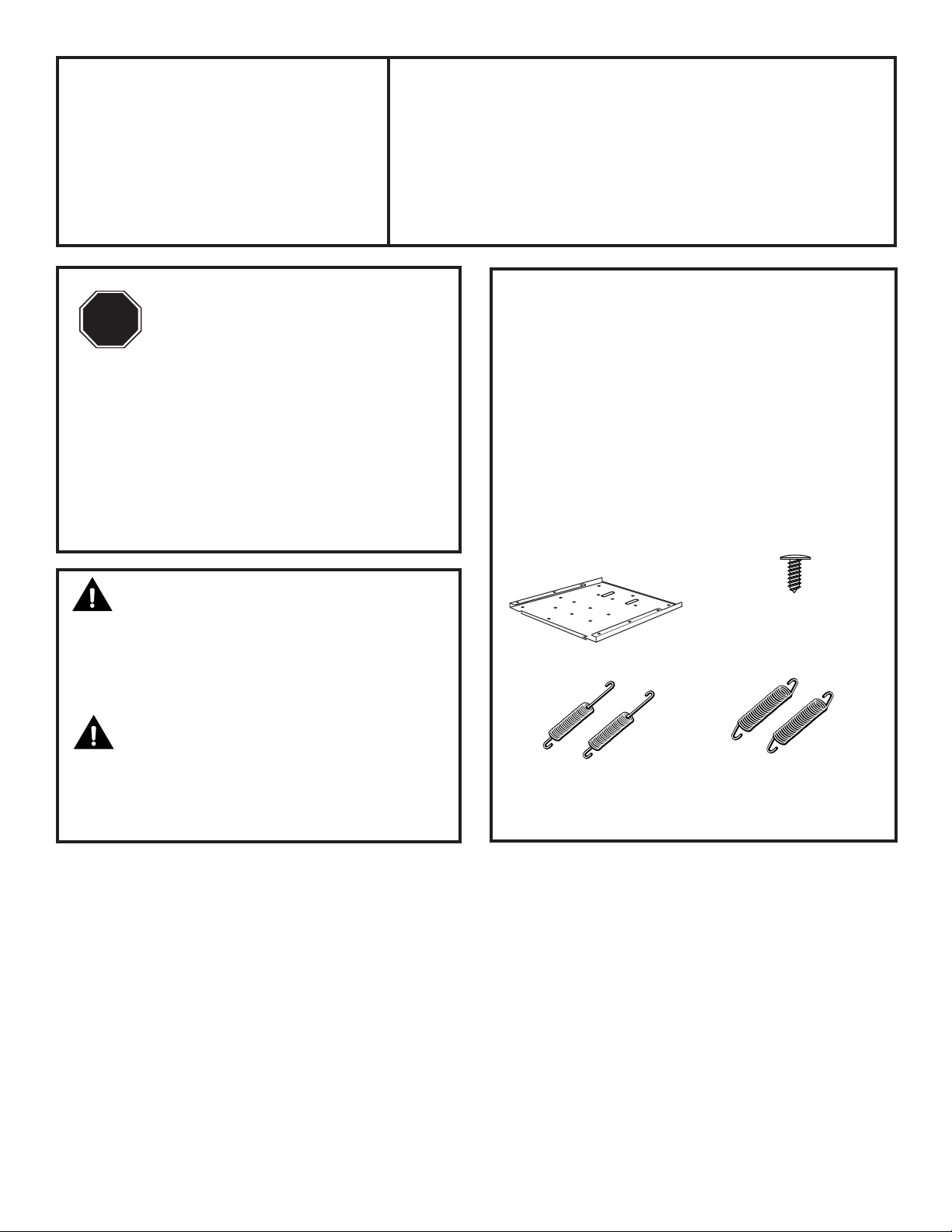
KIT INCLUDES:
WARNING:
To prevent electric shock, disconnect electrical power supply to dishwasher before
changing panels. Do not operate dishwasher
while changing panel.
CAUTION:
On new installations, do not remove wood
base until you are ready to install the dishwasher. The dishwasher will tip over when
the door is opened.
Panel Support
2 Door Springs
To Be Used On All Models
Except PDW8500
9 Phillips Head
Screws, 5/8" Long
2 Door Springs
PDW8500 Only
Page 2
Bottom
Phillips Screws
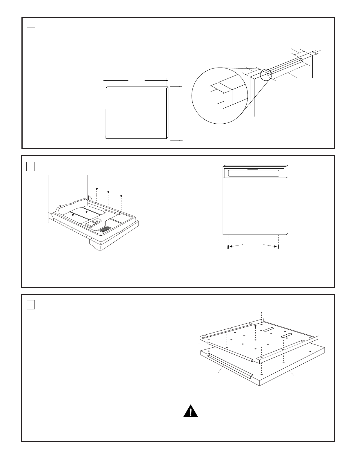
1 PREPARE 3/4" CUSTOM PANEL
Routed Groove
Custom Panel
Drill 1/8" Holes
Support
Panel Trim
Top
Bend
• The custom panel must be sized to the
dimensions shown.
• Rout the top edge of the door panel on the
back side as shown in Figure 1:
– 1/4" deep and 3/8" wide.
– 20" wide (flat surface)
and 1-7/8" from
23-3/4"
each side.
Note: The custom
wood panel should
evenly align with the
3/4" Thick Panel
Appearance Side
bottom of adjacent
cabinets.
2 REMOVE DOOR PANEL
25-7/16"
1/4" Deep
3/8" Wide
Figure 1
1-7/8"
1-7/8"
Back Side
of Panel
3/4"
20" Min.
Flat Surface
Rout 1/4" Deep,
3/8" Wide
Figure 2
• Open dishwasher door.
• Remove the 6 screws along the sides of the
door (Figure 2) holding the inner door to the
outer panel. Retain screws.
3 ASSEMBLE DOOR PANEL
• Remove the protective plastic covering from
the support panel trim.
• Place the custom panel appearance side
down on a flat protected surface. Take care
not to scratch the custom panel or the trim.
• Place the support panel on the back side of
the custom panel such that the top bend fits
into the routed groove. The support panel
and custom panel should be evenly aligned
side to side.
• Select and mark screw holes in the metal
panel where the wood beneath is at least
3/4" thick.
• Use 1/8" bit to drill pilot holes, 5/8" deep
through the support and into the wood
panel at the marked screw holes.
• Secure the wood to the panel with the
screws provided.
Figure 3
• Close the door.
• Remove the two screws at the bottom of the
door panel (Figure 3). Retain screws.
• Remove door panel.
Figure 4
CAUTION:
Do not drill pilot holes too deeply to avoid
damaging the appearance side of the panel.
2
Page 3
4 INSTALL THE ASSEMBLED PANEL
Custom Panel
Bottom
Figure 5
Phillips Screws
Figure 6
Figure 7
• Close the dishwasher door.
• Slide the panel assembly into the escutcheon
lip and hold the panel in place (Figure 5).
• Reinstall the two screws at the bottom of the
door to hold the assembly to the hinge arms
(Figure 6).
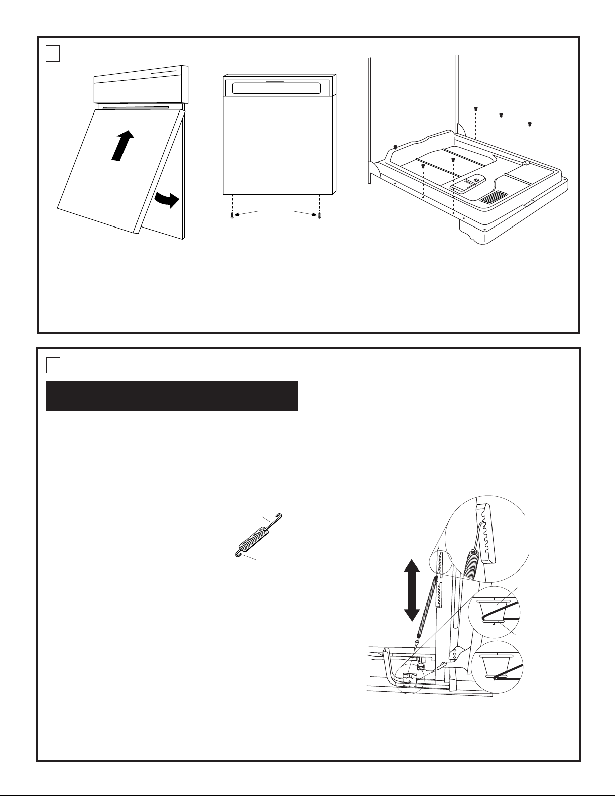
5 REPLACE DOOR SPRINGS
STEP 5 FOR ALL MODELS EXCEPT PDW8500.
GO TO STEP 5A FOR PDW8500.
BEFORE YOU BEGIN: Close and latch the door.
• Remove 2 screws securing the dishwasher to
the underside of the countertop and or sides.
Retain screws.
• Carefully pull dishwasher out from the
cabinet enclosure, approximately 10", until
door springs are exposed.
• Remove the spring from the
right side of the unit first.
• Place the short hook of the
new spring in the cable end.
Insert the long hook into a
notch on the frame bracket.
• Make sure the cable has not
slipped off the pulley.
• Repeat the same procedure on the left side
of the unit. Both springs should be on the
same notch on the frame bracket as shown
in Figure 9.
Long
Hook
Short
Hook
Figure 8
• Open the dishwasher door and reinstall the
original 6 Phillips head screws to hold the inner
door to the panel assembly (Figure 7).
• Close the door.
• When adjusting tension, both springs must be
set to the same position on the side brackets.
• Slide dishwasher back into the original
position.
• Check that door springs do not contact water
line, fill hose, wiring or other components.
• Reinstall the original top or side mounting
screws.
• Turn on water and power.
Note: Increase or decrease
tension as shown. Adjust
both springs to the same
tension setting to correct
balance.
Increase
Insert Long
Hook Over
Frame Bracket
Spring
Tension
Pulley
Decrease
CORRECT
Spring
Tension
Shoulder
TEST DOOR BALANCE
Always hold the dishwasher at the top when
opening the door. The dishwasher will tip
forward when the door is opened.
• Release door latch. Open and release the
door. If the door tends to drop when released,
increase spring tension. If the door tends to
close, decrease spring tension.
INCORRECT
Figure 9
Check to be sure the spring cable is routed correctly before
making spring adjustments. The cable is held in place by
“shoulders” on the pulley. See Figure 9. Check to be sure
the cable has not slipped over the pulley shoulder and onto
the axle.
3
Page 4

5A REPLACE DOOR SPRINGS
CORRECT
INCORRECT
Pulley
Shoulder
INCREASE
DECREASE
FOR MODEL PDW8500 ONLY
BEFORE YOU BEGIN: Close and latch the door.
• Remove 2 screws securing the dishwasher to
the underside of the countertop and or sides.
Retain screws.
• Carefully pull dishwasher out from the cabinet enclosure, approximately 20", until door
springs are exposed.
• Remove the spring from the right side of
the unit first.
• Place one hook of the new spring in the cable
end. Insert the other hook into a notch on the
frame bracket.
• Make sure the cable has not slipped off the
pulley.
• Repeat the same procedure on the left side
of the unit. Both springs should be on the
same notch on the frame bracket as shown
in Figure 10.
TEST DOOR BALANCE
Always hold the dishwasher at the top when
opening the door. The dishwasher will tip
forward when the door is opened.
• Release door latch. Open and release the
door. If the door tends to drop when released,
increase spring tension. If the door tends to
close, decrease spring tension.
• When adjusting tension, both springs must be
set to the same position on the side brackets.
• Slide dishwasher back into the original
position.
• Check that door springs do not contact water
line, fill hose, wiring or other components.
• Reinstall the original top or side mounting
screws.
• Turn on water and power.
Note: To increase tension, use
top hole. To decrease tension
use lower hole. Adjust both
springs to the same tension
setting to correct balance.
Figure 10
Check to be sure the spring cable is routed correctly before
making spring adjustments. The cable is held in place by
“shoulders” on the pulley. See Figure 10. Check to be sure
the cable has not slipped over the pulley shoulder and onto
the axle.
Pub. No. 31-30553 SPECIFICATIONS SUBJECT TO CHANGE WITHOUT NOTICE DWG. NO. 206C1559P092
(ND 923-21) 2/04
Page 5

Panel de puerta con espesor
de 1/4 de pulg. (6 mm)
23-1/2 pulg. (60 cm)
25-1/16 pulg.
(64 cm)
Instrucciones
de instalación
Juego de panel personalizado de
1/4 de pulg. (6 mm) para puerta de
lavavajillas
Juegos de la serie GPF825
GPF825B, Juego de molduras negras
GPF825C, Juego de molduras esmaltadas
GPF825W, Juego de molduras blancas
ANTES DE COMENZAR
PARE
Lea cuidadosamente todas estas
instrucciones.
IMPORTANTE: Conserve estas
instrucciones para uso del inspector local.
IMPORTANTE: Observe todos los
códigos y reglamentos vigentes.
Nota para el instalador: Asegúrese de dejar
estas instrucciones con el consumidor.
Nota para el consumidor: Conserve estas
instrucciones junto con el Manual del
propietario para futura referencia.
ADVERTENCIA:
Antes de cambiar los paneles, desconecte el
suministro de electricidad al lavavajillas para
prevenir el peligro de electrocución. No use el
lavavajillas mientras cambia los paneles ni al
retirar el conjunto del panel de acceso inferior.
PRECAUCIÓN
En instalaciones nuevas, no retire la base
de madera hasta que vaya a instalar el
lavavajillas. El lavavajillas se volteará al abrir
la puerta.
HERRAMIENTAS Y MATERIALES
REQUERIDOS:
• Destornillador en cruz (Phillips) ancho
• Guantes para protegerse de bordes afilados
• Gafas de seguridad
EL JUEGO INCLUYE:
• Bastidor de panel de puerta
• 2 resortes para puerta
Moldura
superior
Panel ajustable
de acero
Bastidor de panel de puerta
totalmente ensamblado
Moldura
lateral
Moldura
inferior
2 resortes de puerta para
todos los modelos excepto
el PDW8500
1 CORTE LOS PANELES
PERSONALIZADOS DE 1/4 DE
PULG. (6 mm) AL TAMAÑO
DESEADO
• Corte el panel de puerta y el panel de acceso
a las dimensiones indicadas en la Figura 1.
NOTA: La moldura que se suministra ocultará
los bordes cortados de los paneles.
Figura 1
Page 6

2 RETIRE EL PANEL DE PUERTA
Tornillos Phillips
inferiores
Figura 2
Figura 3
• Abra la puerta del lavavajillas.
• Saque los 6 tornillos Phillips de los costados
de la puerta (Figura 2) mientras sujeta la
puerta interior al panel exterior. Conserve los
• Retire los dos tornillos que están en la parte
inferior del panel de puerta (Figura 3). Conserve los tornillos.
• Retire el panel de puerta.
tornillos.
3 ARME EL PANEL Y EL BASTIDOR DE MOLDURAS
• Desprenda el plástico protector que cubre las
molduras superiores, inferiores y laterales.
Tornillos de la
Figura 4
moldura superior
• Retire los 3 tornillos que sujetan la moldura
superior al panel de acero (Figura 4). Ponga a
un lado la moldura superior y los 3 tornillos.
Vista en
planta
Deslice
el panel
dentro del
bastidor
Panel
personalizado
Figura 5
• Deslice el panel personalizado de 1/4 de pulg.
(6 mm) dentro del canal situado entre la
moldura y el panel de acero (Figura 5).
• Atornille, sin apretar, los 3 tornillos originales
para unir la moldura superior al panel de
acero.
Figura 6
• Ponga el panel armado sobre una superficie
plana protegida, con el lado decorativo hacia
abajo. Evite rayar el panel personalizado o la
moldura.
• Afloje uno de los 4 tornillos que sujetan el
panel de acero a la moldura (Figura 6).
Presione el panel de acero contra el panel
personalizado y vuelva a apretar el tornillo.
Repita este ajuste con los otros 3 tornillos.
• Ponga la moldura superior a ras contra el
panel personalizado y apriete los 3 tornillos de
la moldura superior.
Tornillos de ajuste del panel
2
Page 7

4 INSTALE EL PANEL ARMADO
Pestaña de
Lámina
la lámina
Tornillos
Figura 7
• Cierre la puerta del lavavajillas.
• Deslice el conjunto del panel dentro de la
pestaña de la lámina (Figura 7).
• Vuelva a atornillar los dos tornillos en la parte
inferior de la puerta para sujetar el conjunto a
Phillips inferiores
Figura 8
• Abra la puerta del lavavajillas y vuelva a
atornillar los 6 tornillos Phillips originales para
sujetar la puerta interior al conjunto de
molduras (Figura 9).
• Cierre la puerta.
los brazos articulados (Figura 8).
5 REEMPLACE LOS RESORTES DE LA PUERTA
PASO 5 EN TODOS LOS MODELOS EXCEPTO EL
PDW8500. REFIÉRASE AL PASO 5A PARA EL
MODELO PDW8500.
ANTES DE COMENZAR: Cierre y enganche la
puerta.
• Retire los 2 tornillos que sujetan el lavavajillas
a la parte inferior de la superficie de cocina o
a los lados. Conserve los tornillos.
• Saque cuidadosamente el lavavajillas, aproximadamente 10 pulg. (25 cm), hasta
Figura 10
Gancho
largo
Gancho
corto
que vea los resortes de la puerta.
• Saque primero el resorte en el lado
derecho de la unidad.
• Ponga el gancho corto del
nuevo resorte en el extremo del
cable. Introduzca el gancho largo en
la ranura que está en el soporte del bastidor.
• Asegúrese de que el cable no se salga de la
polea.
• Repita este procedimiento en el lado
izquierdo de la unidad. Ambos resortes
deben estar en la misma ranura del soporte,
como se indica en la Figura 11.
PRUEBE EL BALANCE DE LA PUERTA
Sujete siempre el lavavajillas por la parte
superior cuando abra la puerta. El lavavajillas
se volteará hacia delante al abrir la puerta.
• Suelte el gancho de la puerta. Abra y suelte la
puerta. Si la puerta tiende a caer al soltarla,
aumente la tensión del resorte. Si la puerta
tiende a cerrarse, reduzca la tensión del
resorte.
• Ambos resortes se deben colocar en la misma
posición en los soportes laterales al ajustar la
tensión.
• Empuje el lavavajillas a su posición original.
• Verifique que los resortes no toquen la tubería
de agua, la manguera de llenado, cables u otros
componentes.
• Vuelva a instalar los tornillos originales de la
parte superior o los costados.
• Abra el grifo de agua y conecte la electricidad.
Nota: Aumente o reduzca la
tensión en la forma indicada.
Ajuste ambos resortes a la misma
tensión para obtener un balance
correcto.
Figura 11
Verifique la ruta que sigue el cable del resorte antes de
ajustar el resorte. Los “rebordes” en la polea mantienen
el cable en posición. Vea la Figura 11. Asegúrese de que
el cable no se haya salido del reborde de la polea y caído
sobre el eje.
Figura 9
Aumente la
tensión
del resorte
Reduzca la
tensión
del resorte
Inserte el gancho
largo sobre el
soporte del bastidor
Polea
CORRECTO
Reborde
INCORRECTO
3
Page 8

5A PRUEBE EL BALANCE DE LA PUERTA
MODELO PDW8500 SOLAMENTE
• Suelte el gancho de la puerta. Abra y suelte la
puerta. Si la puerta tiende a caer al soltarla,
debe aumentar la tensión del resorte. Si la
puerta tiende a cerrarse, debe reducir la
tensión del resorte.
• Si necesita ajustar la tensión del resorte,
retire primero los 2 tornillos que sujetan el
lavavajillas a la parte inferior y los costados
de la superficie de cocina. Conserve los
tornillos. Saque cuidadosamente el
lavavajillas, aproximadamente 20 pulg.
(50 cm), hasta que vea los resortes de la
puerta.
• Sujete siempre el lavavajillas por la parte
superior cuando abra la puerta. El lavavajillas
se volteará hacia delante al abrir la puerta.
• Vea la Figura 12 para ajustar la tensión de los
resortes. Ambos resortes se deben colocar en
la misma posición en los soportes laterales al
ajustar la tensión.
• Empuje el lavavajillas a su posición original.
• Verifique que los resortes no toquen la
tubería de agua, la manguera de llenado,
cables u otros componentes.
• Vuelva a instalar los tornillos originales de la
parte superior o los costados.
• Abra el grifo de agua y conecte la electricidad.
Nota: Use el orificio superior
para aumentar la tensión. Use
el orificio inferior para reducir
la tensión. Ajuste ambos
resortes a la misma tensión
para obtener un balance
correcto.
AUMENTAR
REDUCIR
Polea
CORRECTO
INCORRECTO
Reborde
Figura 12
Verifique la ruta que sigue el cable del resorte
antes de ajustar el resorte. Los “rebordes” en
la polea mantienen el cable en posición. Vea la
Figura 12. Asegúrese de que el cable no se
haya salido del reborde de la polea y caído
sobre el eje.
Pub. No. 31-30552 ESPECIFICACIONES SUJETAS A CAMBIO SIN PREVIO AVISO DWG. NO. 206C1559P091
(ND 923-20) 2/04
 Loading...