

GE AF-650 GP, GP AF-650 Quick Manual

GE
TM
AF-650 GP
General Purpose Drive
Quick Guide
Guia rapida
Kurzanleitung
Guide rapide
Guida rapida
Safety AF-650 GP Quick Guide
1Safety
1
1
1.1.1 Safety
WARNING
HIGH VOLTAGE!
Adjustable frequency drives contain high voltage when
connected to AC line power. Installation, start-up, and
maintenance should be performed by qualified personnel
only. Failure to perform installation, start-up, and
maintenance by qualified personnel could result in death
or serious injury.
High Voltage
Adjustable frequency drives are connected to hazardous
AC line voltage. Extreme care should be taken to protect
against shock. Only trained personnel familiar with
electronic equipment should install, start, or maintain this
equipment.
WARNING
UNINTENDED START!
When the adjustable frequency drive is connected to AC
line power, the motor may start at any time. The
adjustable frequency drive, motor, and any driven
equipment must be in operational readiness. Failure to be
in operational readiness when the adjustable frequency
drive is connected to AC line power could result in death,
serious injury, equipment, or property damage.
Voltage Power Size
200–240V
380–480V
525–600V
525–690V
Table 1.1 Discharge Time
Symbols
The following symbols are used in this manual.
0.25–3.7kW 0.33–5HP 4 minutes
5.5–37kW 7.5–50HP 15 minutes
0.37–7.5kW 0.5–10HP 4 minutes
11–75kW 15–100HP 15 minutes
90–200kW 125–300HP 20 minutes
250–800kW 350–1200HP 40 minutes
0.37–7.5kW 0.5–10HP 4 minutes
11–75kW 15–100HP 15 minutes
11–75kW 15–100HP 15 minutes
90–315kW 125–400HP 20 minutes
355–1200kW 500–1350HP 30 minutes
Minimum Waiting
Time
WARNING
Indicates a potentially hazardous situation which, if not
avoided, could result in death or serious injury.
CAUTION
Indicates a potentially hazardous situation which, if not
avoided, may result in minor or moderate injury. It may
also be used to alert against unsafe practices.
Unintended Start
When the adjustable frequency drive is connected to the
AC line power, the motor may be started by means of an
external switch, a serial bus command, an input reference
signal, or a cleared fault condition. Use appropriate
precautions to guard against an unintended start.
WARNING
DISCHARGE TIME!
Adjustable frequency drives contain DC link capacitors that
can remain charged even when AC line power is disconnected. To avoid electrical hazards, remove AC line power
from the adjustable frequency drive before doing any
service or repair and wait the amount of time specified in
Table 1.1. Failure to wait the specified time after power has
been removed prior to doing service or repair on the unit
could result in death or serious injury.
CAUTION
Indicates a situation that may result in equipment or
property damage-only accidents.
NOTE
Indicates highlighted information that should be observed
in order to avoid mistakes or operate equipment at less
than optimal performance.
Approvals
DET-759A 1

2
Introduction AF-650 GP Quick Guide
2Introduction
Illustration 2.1 Exploded View Unit Sizes 12-13, IP20
NOTE
Please consult the AF-650 GP Instruction Manual for other unit sizes.
1 Keypad 10 Motor output terminals 96 (U), 97 (V), 98 (W)
2 RS-485 serial bus connector (+68, -69) 11 Relay 1 (01, 02, 03)
3 Analog I/O connector 12 Relay 2 (04, 05, 06)
4 Keypad input plug 13 Brake (-81, +82) and load sharing (-88, +89) terminals
5 Analog switches (A53), (A54) 14 Line power input terminals 91 (L1), 92 (L2), 93 (L3)
6 Cable strain relief / PE ground 15 USB connector
7 Decoupling plate 16 Serial bus terminal switch
8 Grounding clamp (PE) 17 Digital I/O and 24 V power supply
9 Shielded cable grounding clamp and strain relief 18 Control cable coverplate
2DET-759A

Installation AF-650 GP Quick Guide
3
3 Installation
3.1 Installation Site Checklist
The drive relies on the ambient air for cooling.
•
Observe the limits on ambient air temperature for
optimal operation
Ensure that the installation location has sufficient
•
support strength to mount the drive
Keep the drive interior free from dust and dirt.
•
Ensure that the components stay as clean as
possible. In construction areas, provide a
protective covering. Optional IP54 (NEMA 12)
enclosures may be necessary.
Keep the manual, drawings, and diagrams
•
accessible for detailed installation and operation
instructions. It is important that the manual is
available for equipment operators.
Locate equipment as near to the motor as
•
possible. Keep motor cables as short as possible.
Check the motor characteristics for actual
tolerances. Do not exceed
1000 ft [300 m] for unshielded motor
•
leads
500 ft [150 m] for shielded cable.
•
3.3 Mechanical Installation
3.3.1 Cooling
To provide cooling airflow, mount the unit to a
•
solid flat surface or to the optional backplate (see
3.3.3 Mounting)
Top and bottom clearance for air cooling must be
•
provided. Generally, 4–10 in [100–225 mm] is
required. See Illustration 3.1 for clearance
requirements
Improper mounting can result in overheating and
•
reduced performance.
Derating for temperatures starting between 104°F
•
[40°C]) and 122°F [50°C] and elevation 3,300 ft
[1,000 m] above sea level must be considered.
See the equipment Design Guide for detailed
information.
3
3.2 Adjustable Frequency Drive and Motor
Pre-installation Checklist
Compare the model number of unit on the
•
nameplate to what was ordered to verify the
proper equipment
Ensure each of the following are rated for the
•
same voltage:
Line power
Drive
Motor
Ensure that drive output current rating is equal to
•
or greater than motor full load current for peak
motor performance.
Motor size and drive power must match
for proper overload protection.
If drive rating is less than motor, full
motor output cannot be achieved.
Illustration 3.1 Top and Bottom Cooling Clearance
DET-759A 3

3
Installation AF-650 GP Quick Guide
Voltage Power Size Clearance a/b
0.25–3.7kW 0.33–5HP 100mm / 4in
200–240V
380–480V
525–600V
525–690V all 225mm / 10in
Table 3.1 Minimum Airflow Clearance Requirements
5.5–22kW 7.5–30HP 200mm / 8in
> 22kW / 30HP 225mm / 10in
0.37–7.5kW 0.5–10HP 100mm / 4in
11–45kW 15–60HP 200mm / 8in
> 45kW / 60HP 225mm / 10in
0.37–7.5kW 0.5–10HP 100mm / 4in
11–45kW 15–60HP 200mm / 8in
> 45kW / 60HP 225mm / 10in
3.3.2 Lifting
Illustration 3.2 Proper Mounting with Backplate
Check the weight of the unit to determine a safe
•
lifting method
Ensure that the lifting device is suitable for the
•
task
If necessary, plan for a hoist, crane, or forklift with
•
the appropriate rating to move the unit
For lifting, use hoist rings on the unit, when
•
provided
3.3.3 Mounting
Mount the unit vertically
•
The drive allows side by side installation.
•
Ensure that the strength of the mounting location
•
will support the unit weight
Mount the unit to a solid flat surface or to the
•
optional backplate to provide cooling airflow (see
Illustration 3.2 and Illustration 3.3).
Improper mounting can result in overheating and
•
reduced performance.
Use the slotted mounting holes on the unit for
•
wall mounting, when provided.
Item A is a backplate properly installed for required airflow
to cool the unit.
Illustration 3.3 Proper Mounting with Railings
NOTE
Backplate is needed when mounted on railings.
4DET-759A

Installation AF-650 GP Quick Guide
3
3.4 Electrical Installation
This section contains detailed instructions for wiring the drive. The following tasks are described.
Wiring the motor to the drive output terminals
•
Wiring the AC line power to the drive input terminals
•
Connecting control and serial communication wiring
•
After power has been applied, checking input and motor power; programming control terminals for their intended
•
functions
3
Illustration 3.4 Basic Wiring Schematic Drawing.
A=Analog, D=Digital
Terminal 37 is used for Safe Stop. For Safe Stop installation instructions, refer to the Design Guide.
*The brake chopper factory option must be ordered to use dynamic braking resistors.
**This is available when ordering the brake chopper option on unit size 23 and above drives.
DET-759A 5

Installation AF-650 GP Quick Guide
3
3.4.1 Requirements
WARNING
EQUIPMENT HAZARD!
Rotating shafts and electrical equipment can be hazardous.
All electrical work must conform to national and local
electrical codes. It is strongly recommended that installation, start-up, and maintenance be performed only by
trained and qualified personnel. Failure to follow these
guidelines could result in death or serious injury.
CAUTION
WIRING ISOLATION!
Run input power, motor wiring and control wiring in three
separate metallic conduits or use separated shielded cable
for high frequency noise isolation. Failure to isolate power,
motor and control wiring could result in less than
optimum adjustable frequency drive and associated
equipment performance.
For your safety, comply with the following requirements.
Electronic controls equipment is connected to
•
hazardous AC line voltage. Extreme care should
be taken to protect against electrical hazards
when applying power to the unit.
Run motor cables from multiple adjustable
•
frequency drives separately. Induced voltage from
output motor cables run together can charge
equipment capacitors even with the equipment
turned off and locked out.
Overload and Equipment Protection
An electronically activated function within the
•
adjustable frequency drive provides overload
protection for the motor. The overload calculates
the level of increase to activate timing for the trip
(controller output stop) function. The higher the
current draw, the quicker the trip response. The
overload provides Class 20 motor protection. See
7 Warnings and Alarm for details on the trip
function.
Because the motor wiring carries high frequency
•
current, it is important that wiring for line power,
motor power, and control is run separately. Use
metallic conduit or separated shielded wire.
Failure to isolate power, motor, and control
wiring could result in less than optimum
equipment performance.
All adjustable frequency drives must be provided
•
with short-circuit and overcurrent protection.
Input fusing is required to provide this
protection, see Illustration 3.5. Fuses must be
provided by the installer as part of installation.
See maximum fuse ratings in 9.1.2 CE Compliance.
Illustration 3.5 Fuses
Wire Type and Ratings
All wiring must comply with local and national
•
regulations regarding cross-section and ambient
temperature requirements.
GE recommends that all power connections be
•
made with a minimum 167°F [75°C] rated copper
wire.
3.4.2 Grounding Requirements
WARNING
GROUNDING HAZARD!
For operator safety, it is important to ground drive
properly in accordance with national and local electrical
codes as well as instructions contained within these
instructions. Ground currents are higher than 3.5 mA.
Failure to ground drive properly could result in death or
serious injury.
NOTE
It is the responsibility of the user or certified electrical
installer to ensure correct grounding of the equipment in
accordance with national and local electrical codes and
standards.
Follow all local and national electrical codes to
•
ground electrical equipment properly.
Proper protective grounding for equipment with
•
ground currents higher than 3.5 mA must be
established, see Leakage Current (>3.5 mA)
A dedicatedground wire is required for input
•
power, motor power and control wiring
Use the clamps provided with on the equipment
•
for proper ground connections
6DET-759A
Installation AF-650 GP Quick Guide
3
Do not ground one drive to another in a “daisy
•
chain” fashion
Keep the ground wire connections as short as
•
possible
Use of high-strand wire to reduce electrical noise
•
is recommended
Follow the motor manufacturer wiring
•
requirements
3.4.2.1 Leakage Current (>3.5 mA)
Follow national and local codes regarding protective
grounding of equipment with a leakage current > 3.5 mA.
Drive technology implies high frequency switching at high
power. This will generate a leakage current in the ground
connection. A fault current in the drive at the output
power terminals might contain a DC component which can
charge the filter capacitors and cause a transient ground
current. The ground leakage current depends on various
system configurations including RFI filtering, shielded
motor cables, and drive power.
EN/IEC61800-5-1 (Power Drive System Product Standard)
requires special care if the leakage current exceeds 3.5m A.
Grounding must be reinforced in one of the following
ways:
Ground wire of at least 0.0155 in2 [10mm2]
•
Two separate ground wires both complying with
•
the dimensioning rules
See EN 60364-5-54 § 543.7 for further information.
Using RCDs
Where residual current devices (RCDs), also known as
ground leakage circuit breakers (ELCBs), are used, comply
with the following:
Use RCDs of type B only which are capable of
detecting AC and DC currents
Use RCDs with an inrush delay to prevent faults
due to transient ground currents
Dimension RCDs according to the system configuration and environmental considerations
3.4.2.2 Grounding Using Shielded Cable
Grounding clamps are provided for motor wiring (see
Illustration 3.6).
Illustration 3.6 Grounding with Shielded Cable
3.4.3 Motor Connection
WARNING
INDUCED VOLTAGE!
Run output motor cables from multiple adjustable
frequency drives separately. Induced voltage from output
motor cables run together can charge equipment
capacitors even with the equipment turned off and locked
out. Failure to run output motor cables separately could
result in death or serious injury.
For maximum wire sizes, see Table 10.1
•
Comply with local and national electrical codes
•
for cable sizes.
Motor wiring knockouts or access panels are
•
provided at the base of IP21 and higher (Nema 1,
12, and 4/4X Indoor) units
Do not install power factor correction capacitors
•
between the adjustable frequency drive and the
motor
Do not wire a starting or pole-changing device
•
between the adjustable frequency drive and the
motor.
Connect the 3-phase motor wiring to terminals
•
96 (U), 97 (V), and 98 (W).
Ground the cable in accordance with grounding
•
instructions provided.
Torque terminals in accordance with the
•
information provided in
Follow the motor manufacturer wiring
•
requirements
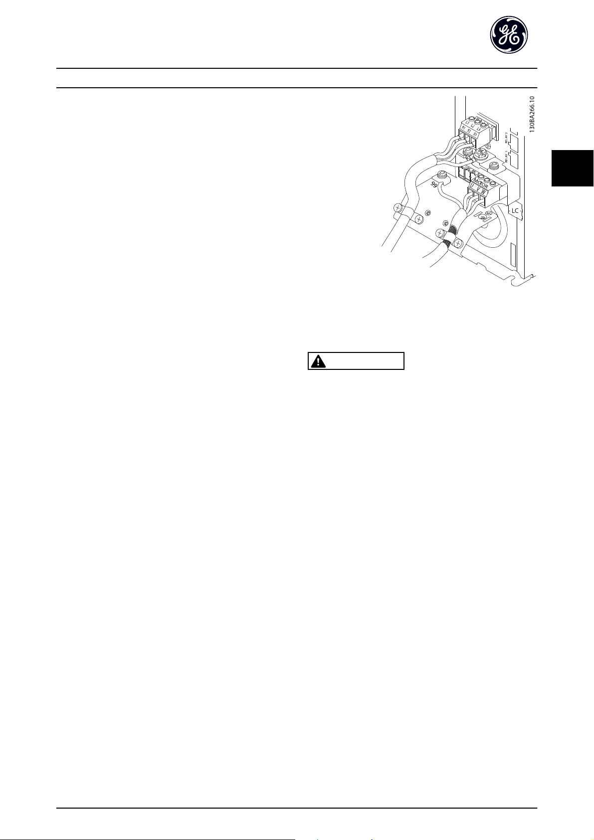
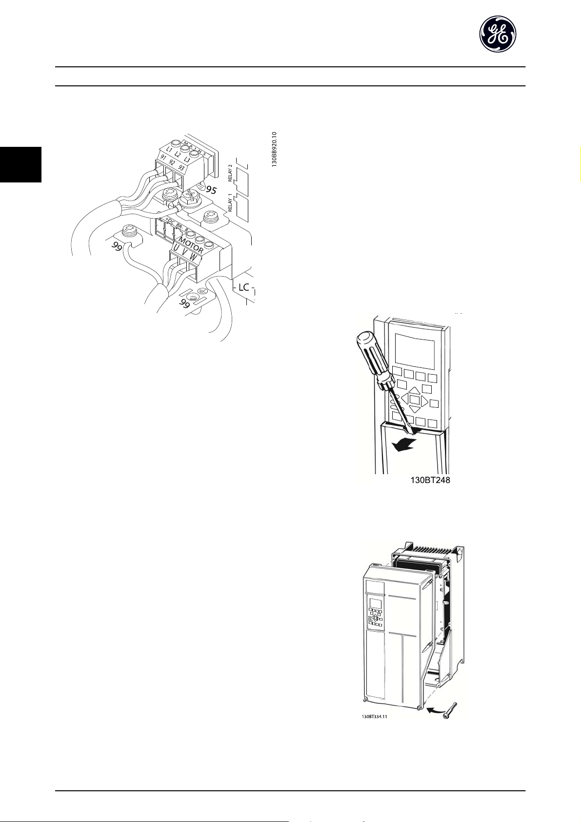
Illustration 3.7 represents line power input, motor, and
ground grounding for basic adjustable frequency drives.
3
DET-759A 7
Installation AF-650 GP Quick Guide
3
Actual configurations vary with unit types and optional
equipment.
Illustration 3.7 Example of Motor, Line Power and Ground Wiring
3.4.5 Control Wiring
Isolate control wiring from high power
•
components in the adjustable frequency drive.
If the adjustable frequency drive is connected to
•
a thermistor, for PELV isolation, optional
thermistor control wiring must be reinforced/
double insulated. A 24 VDC supply voltage is
recommended.
3.4.5.1 Access
Remove access coverplate with a screwdriver. See
•
Illustration 3.8.
Or remove front cover by loosening attaching
•
screws. See Illustration 3.9.
Tightening torque for front cover is 2.0Nm for
unit size 15 and 2.2Nm for unit sizes 2X and 3X.
3.4.4 AC Line Power Connection
Size wiring based upon the input current of the
•
drive. For maximum wire sizes, see Table 10.1.
Comply with local and national electrical codes
•
for cable sizes.
Connect 3-phase AC input power wiring to
•
terminals L1, L2, and L3 (see Illustration 3.7).
Depending on the configuration of the
•
equipment, input power will be connected to the
line power input terminals or the input
disconnect.
Ground the cable in accordance with grounding
•
instructions provided in 3.4.2 Grounding
Requirements
All adjustable frequency drives may be used with
•
an isolated input source as well as with ground
reference power lines. When supplied from an
isolated line power source (IT line or floating
delta) or TT/TN-S power line with a grounded leg
(grounded delta), set 14-50 RFI Filter to OFF.
When off, the internal RFI filter capacitors
between the chassis and the intermediate circuit
are isolated to avoid damage to the intermediate
circuit and to reduce ground capacity currents in
accordance with IEC 61800-3.
Illustration 3.8 Control Wiring Access for IP20 / Open Chassis
Enclosures
Illustration 3.9 Control Wiring Access for IP55 / Nema 12 and
IP66 / Nema 4/4X Indoor
8DET-759A

Installation AF-650 GP Quick Guide
3
3.4.5.2 Control Terminal Types
Illustration 3.10 and shows the removable adjustable
frequency drive connectors. Terminal functions and default
settings are summarized in Table 3.2.
Illustration 3.10 Control Terminal Locations
Illustration 3.11 Terminal Numbers
Connector 1 provides four programmable digital
•
input terminals, two additional digital terminals
programmable as either input or output, a 24V
DC terminal supply voltage, and a common DC
voltage for optional customer-supplied 24 V. A
digital input for STO (Safe Torque Off) function.
Connector 2 terminals (+)68 and (-)69 are for an
•
RS-485 serial communications connection
Connector 3 provides two analog inputs, one
•
analog output, 10V DC supply voltage, and
commons for the inputs and output
Connector 4 is a USB port available for use with
•
the DCT-10
Also provided are two Form C relay outputs that
•
are in various locations depending upon the
adjustable frequency drive configuration and size.
Some options available for ordering with the unit
•
may provide additional terminals. See the manual
provided with the equipment option.
See 8.1 General Technical Data for terminal ratings details.
Terminal description
Default
Terminal Parameter
12, 13 - +24V DC 24 V DC supply
18 E-01 [8] Start
19 E-02 [10] Reversing
32 E-05 [0] No
33 E-06 [0] No
27 E-03 [0] No
29 E-04 [14] JOG
20 - Common for digital
37 - Safe Torque
39 -
42 AN-50 [0] No
50 - +10V DC 10V DC analog supply
53 AN-1# Reference Analog input.
54 AN-2# Feedback
55 -
setting Description
Digital inputs/outputs
operation
operation
operation
Off (STO)
Analog inputs/outputs
operation
voltage. Maximum
output current is
200mA total for all
24V loads. Usable for
digital inputs and
external transducers.
Digital inputs.
Selectable for either
digital input or
output. Default setting
is input.
inputs and 0V
potential for 24V
supply.
Safe input. Used for
STO.
Common for analog
output
Programmable analog
output. The analog
signal is 0–20 mA or
4–20 mA at a
maximum of 500
voltage. 15mA
maximum commonly
used for potentiometer or thermistor.
Selectable for voltage
or current. Switches
A53 and A54 select
mA or V.
Common for analog
input
3
Ω
DET-759A 9

Installation AF-650 GP Quick Guide
3
Terminal description
Default
Terminal Parameter
61 -
68 (+) O-3# RS-485 Interface. A
69 (-) O-3#
01, 02, 03 E-24
04, 05, 06 E-24 [0] No
Table 3.2 Terminal Description
setting Description
Serial communication
Relays
[0] No
operation
operation
Integrated RC filter for
cable screen. ONLY for
connecting the shield
when experiencing
EMC problems.
control card switch is
provided for
termination resistance.
Form C relay output.
Usable for AC or DC
voltage and resistive
or inductive loads.
3.4.5.3 Wiring to Control Terminals
Control terminal connectors can be unplugged from the
drive for ease of installation, as shown in Illustration 3.10.
1. Open the contact by inserting a small screwdriver
into the slot above or below the contact, as
shown in Illustration 3.12.
2. Insert the bared control wire into the contact.
3. Remove the screwdriver to fasten the control wire
into the contact.
4. Ensure the contact is firmly established and not
loose. Loose control wiring can be the source of
equipment faults or less than optimal operation.
If the ground potential between the adjustable frequency
drive and the PLC is different, electric noise may occur that
will disturb the entire system. Solve this problem by fitting
an equalizing cable next to the control cable. Minimum
2
cable cross-section: 0.025 in
(16 mm2).
50/60Hz ground loops
With very long control cables, ground loops may occur. To
eliminate ground loops, connect one end of the shield-toground with a 100nF capacitor (keeping leads short).
Avoid EMC noise on serial communication
This terminal is grounded via an internal RC link. Use
twisted-pair cables to reduce interference between
conductors. The recommended method is shown below:
Alternatively, the connection to terminal 61 can be
omitted:
3.4.5.5 Control Terminal Functions
Drive functions are commanded by receiving control input
signals.
Illustration 3.12 Connecting Control Wiring
3.4.5.4 Using Shielded Control Cables
Correct shielding
The preferred method in most cases is to secure control
and serial communication cables with shielding clamps
provided at both ends to ensure best possible high
frequency cable contact.
10 DET-759A
Each terminal must be programmed for the
•
function it will be supporting in the parameters
associated with that terminal. SeeTable 3.2 for
terminals and associated parameters.
It is important to confirm that the control
•
terminal is programmed for the correct function.
See 5 User Interface for details on accessing
parameters and for details on programming.

Installation AF-650 GP Quick Guide
3
The default terminal programming is intended to
•
initiate drive functioning in a typical operational
mode.
3.4.5.6 Terminal 53 and 54 Switches
Analog input terminals 53 and 54 can select
•
either voltage (-10–10V) or current (0/4–20mA)
input signals
Remove power to the drive before changing
•
switch positions
Set switches A53 and A54 to select the signal
•
type. U selects voltage, I selects current.
The switches are accessible when the Keypad has
•
been removed (see Illustration 3.13). Note that
some option cards available for the unit may
cover these switches and must be removed to
change switch settings. Always remove power to
the unit before removing option cards.
Terminal 53 default is for a speed reference signal
•
in open-loop set in DR-61 Terminal 53 Switch
Setting
Terminal 54 default is for a feedback signal in
•
closed-loop set in DR-63 Terminal 54 Switch
Setting
130BT310.10
Illustration 3.13 Location of Terminals 53 and 54 Switches and
Bus Termination Switch
3.4.5.7 Terminal 37
Terminal 37 Safe Stop Function
The AF-650 GP and is available with safe stop functionality
via control terminal 37. Safe stop disables the control
voltage of the power semiconductors of the drive output
stage which in turn prevents generating the voltage
required to rotate the motor. When the Safe Stop (T37) is
activated, the drive issues an alarm, trips the unit, and
coasts the motor to a stop. Manual restart is required. The
safe stop function can be used for stopping the drive in
emergency stop situations. In the normal operating mode
when safe stop is not required, use the adjustable
frequency drive’s regular stop function instead. When
automatic restart is used – the requirements under ISO
12100-2 paragraph 5.3.2.5 must be fulfilled.
Liability Conditions
It is the responsibility of the user to ensure personnel
installing and operating the Safe Stop function:
Read and understand the safety regulations
•
concerning health and safety/accident prevention
Understand the generic and safety guidelines
•
given in this description and the extended
description in the Design Guide
Have a good knowledge of the generic and safety
•
standards applicable to the specific application
User is defined as: integrator, operator, servicing,
maintenance staff.
Standards
Use of safe stop on terminal 37 requires that the user
satisfies all provisions for safety including relevant laws,
regulations and guidelines. The optional safe stop function
complies with the following standards.
EN 954-1: 1996 Category 3
IEC 60204-1: 2005 category 0 – uncontrolled stop
IEC 61508: 1998 SIL2
IEC 61800-5-2: 2007 – safe torque off (STO)
function
IEC 62061: 2005 SIL CL2
ISO 13849-1: 2006 Category 3 PL d
ISO 14118: 2000 (EN 1037) – prevention of
unexpected start-up
The information and instructions of the instruction manual
are not sufficient for a proper and safe use of the safe stop
functionality. The related information and instructions of
the relevant Design Guide must be followed.
3
DET-759A 11

Installation AF-650 GP Quick Guide
3
Protective Measures
Safety engineering systems may only be installed
•
and commissioned by qualified and skilled
personnel
The unit must be installed in an IP54 cabinet or
•
in an equivalent environment
The cable between terminal 37 and the external
•
safety device must be short circuit protected
according to ISO 13849-2 table D.4
If any external forces influence the motor axis
•
(e.g. suspended loads), additional measures (e.g. a
safety holding brake) are required in order to
eliminate hazards.
Safe Stop Installation and Set-up
WARNING
SAFE STOP FUNCTION!
The safe stop function does NOT isolate AC line voltage to
the drive or auxiliary circuits. Perform work on electrical
parts of the drive or the motor only after isolating the AC
line voltage supply and waiting the length of time
specified under Safety in this manual. Failure to isolate the
AC line voltage supply from the unit and waiting the time
specified could result in death or serious injury.
the jumper is not sufficient to avoid shortcircuiting. (See jumper on Illustration 3.14.)
2. Connect an external Safety monitoring relay via a
NO safety function (the instruction for the safety
device must be followed) to terminal 37 (safe
stop) and either terminal 12 or 13 (24V DC). The
safety monitoring relay must comply with
Category 3 (EN 954-1) / PL “d” (ISO 13849-1).
It is not recommended to stop the drive by using
•
the Safe Torque Off function. If a running drive is
stopped by using the function, the unit will trip
and stop by coasting. If this is not acceptable,
e.g. causes danger, the drive and machinery must
be stopped using the appropriate stopping mode
before using this function. Depending on the
application, a mechanical brake may be required.
Concerning synchronous and permanent magnet
•
motor adjustable frequency drives in case of a
multiple IGBT power semiconductor failure: In
spite of the activation of the Safe torque off
function, the drive system can produce an
alignment torque which maximally rotates the
motor shaft by 180/p degrees. p denotes the pole
pair number.
This function is suitable for performing
•
mechanical work on the drive system or affected
area of a machine only. It does not provide
electrical safety. This function should not be used
as a control for starting and/or stopping the
drive.
The following requirements have to be met to perform a
safe installation of the drive:
1. Remove the jumper wire between control
terminals 37 and 12 or 13. Cutting or breaking
Illustration 3.14 Jumper between Terminal 12/13 (24V) and 37
12 DET-759A

Installation AF-650 GP Quick Guide
3
3
Illustration 3.15 Installation to Achieve a Stopping Category 0 (EN 60204-1) with Safety Cat. 3 (EN 954-1) / PL “d” (ISO 13849-1).
1 Safety device Cat. 3 (circuit interrupt device, possibly
with release input)
2Door contact 8 Motor
3 Contactor (Coast) 9 5V DC
4Drive 10 Safe channel
5 Line power 11 Short-circuit protected cable (if not inside installation cabinet)
6 Control board
Safe Stop Commissioning Test
After installation and before first operation, perform a commissioning test of the installation making use of safe stop. In
addition, perform the test after each modification of the installation.
7Inverter
DET-759A 13
3
Installation AF-650 GP Quick Guide
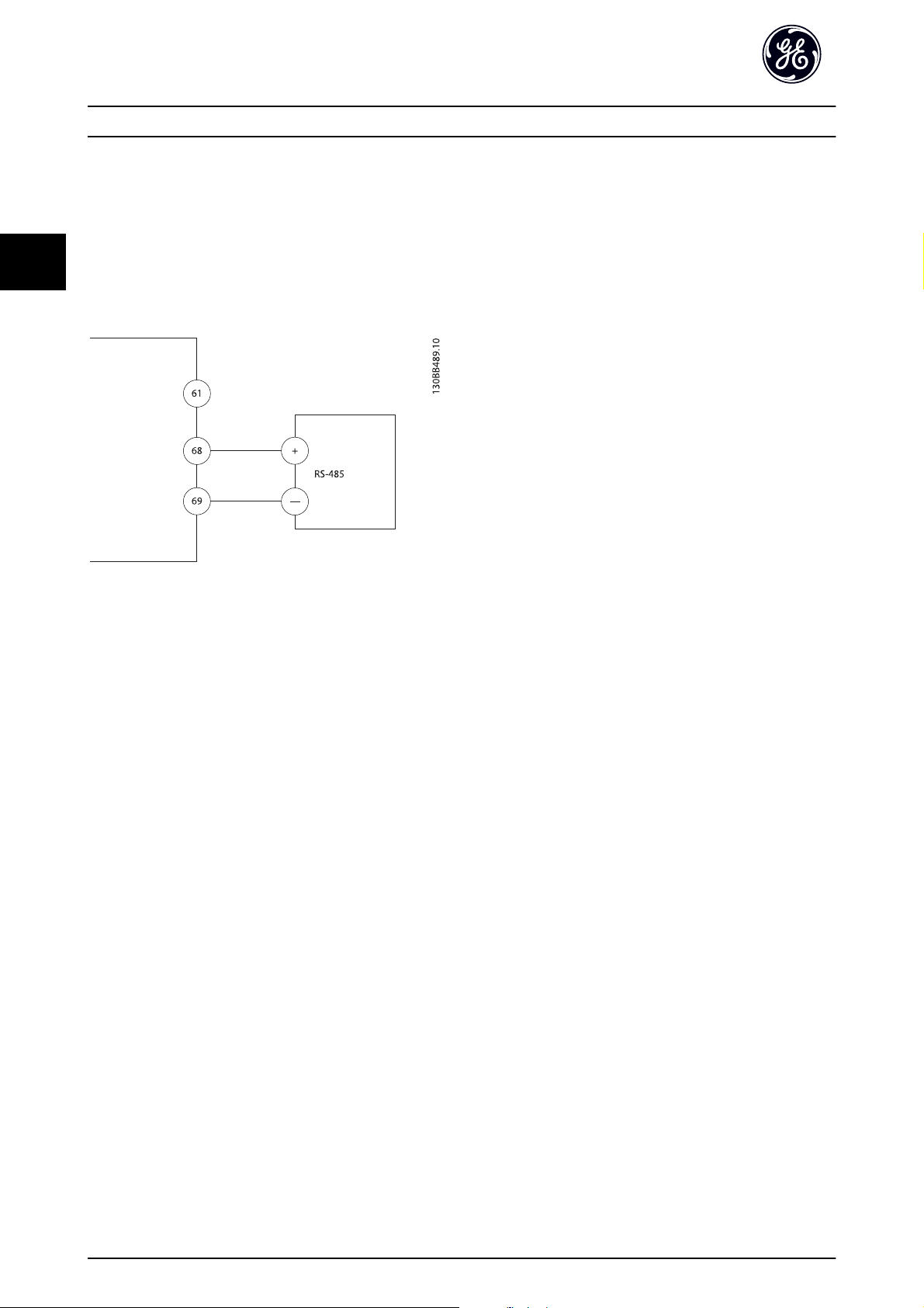
3.4.6 Serial Communication
Connect RS-485 serial communication wiring to terminals
(+)68 and (-)69.
A shielded serial communication cable is
•
recommended
See 3.4.2 Grounding Requirements for proper
•
grounding
Illustration 3.16 Serial Communication Wiring Diagram
For basic serial communication set-up, select the following
1. Protocol type in O-30 Protocol.
2. Adjustable frequency drive address in
O-31 Address.
3. Baud rate in O-32 Drive Port Baud Rate.
Two communication protocols are internal to the
•
drive.
Drive profile
Modbus RTU
Functions can be programmed remotely using
•
the protocol software and RS-485 connection or
in parameter group O-## Options / Comms
Selecting a specific communication protocol
•
changes various default parameter settings to
match that protocol’s specifications along with
making additional protocol-specific parameters
available.
Option cards which can be installed in the
•
adjustable frequency drive are available to
provide additional communication protocols. See
the option card documentation for installation
and operation manual.
14 DET-759A

Start Up and Functional Tes... AF-650 GP Quick Guide
4
4 Start Up and Functional Testing
4.1 Pre-start
4.1.1 Safety Inspection
WARNING
HIGH VOLTAGE!
If input and output connections have been connected
improperly, there is potential for high voltage on these
terminals. If power leads for multiple motors are
improperly run through the same conduit, there is a
potential for leakage current to charge capacitors within
the drive, even when disconnected from line power input.
For initial start-up, make no assumptions about power
components. Follow pre-start procedures. Failure to follow
pre-start procedures could result in personal injury or
damage to equipment.
1. Input power to the unit must be OFF and locked
out. Do not rely on the drive disconnect switches
for input power isolation.
2. Verify that there is no voltage on input terminals
L1 (91), L2 (92), and L3 (93), phase-to-phase and
phase-to-ground,
3. Verify that there is no voltage on output
terminals 96 (U), 97 (V), and 98 (W), phase-tophase and phase-to-ground.
4. Confirm continuity of the motor by measuring
ohm values on U-V (96-97), V-W (97-98), and W-U
(98-96).
5. Check for proper grounding of the drive as well
as the motor.
6. Inspect the drive for loose connections on
terminals.
7. Record the following motor nameplate data:
power, voltage, frequency, full load current, and
nominal speed. These values are needed to
program motor nameplate data later.
8. Confirm that the supply voltage matches voltage
of drive and motor.
4
DET-759A 15
Start Up and Functional Tes... AF-650 GP Quick Guide
4.1.2 Start-up Check List
CAUTION
Before applying power to the unit, inspect the entire installation as detailed in Table 4.1. Check mark those items when
completed.
4
Inspect for Description
Auxiliary equipment
Cable routing
Control wiring
Cooling clearance
EMC considerations
Environmental considerations
Fusing and circuit breakers
Grounding
Input and output power wiring
Panel interior
Switches
Vibration
Look for auxiliary equipment, switches, disconnects, or input fuses/circuit
•
breakers that may reside on the input power side of the adjustable frequency
drive or output side to the motor. Ensure that they are ready for full speed
operation.
Check function and installation of any sensors used for feedback to the drive.
•
Remove power factor correction caps on motor(s), if present.
•
Ensure that input power, motor wiring, and control wiring are separated or in
•
three separate metallic conduits for high frequency noise isolation.
Check for broken or damaged wires and loose connections.
•
Check that control wiring is isolated from power and motor wiring for noise
•
immunity.
Check the voltage source of the signals, if necessary.
•
The use of shielded cable or twisted pair is recommended. Ensure that the
•
shield is terminated correctly.
Measure to make sure that the top and bottom clearance is adequate to
•
ensure proper airflow for cooling.
Check for proper installation regarding electromagnetic compatibility.
•
See equipment label for the maximum ambient operating temperature limits.
•
Humidity levels must be 5%–95% non-condensing.
•
Check for proper fusing or circuit breakers.
•
Check that all fuses are inserted firmly and in operational condition and that all
•
circuit breakers are in the open position.
The unit requires a ground wire from its chassis to the building ground.
•
Check for good ground connections that are tight and free of oxidation.
•
Grounding to conduit or mounting the back panel to a metal surface is not a
•
suitable ground.
Check for loose connections.
•
Check that motor and line power are in separate conduits or separated
•
shielded cables.
Inspect to ensure that the unit interior is free of dirt, metal chips, moisture, and
•
corrosion.
Ensure that all switch and disconnect settings are in the proper positions.
•
Check that the unit is mounted solidly or that shock mounts are used, as
•
necessary.
Check for an unusual amount of vibration.
•
☑
Table 4.1 Start-up Check List
16 DET-759A

Start Up and Functional Tes... AF-650 GP Quick Guide
4
4.2 Applying Power to the Adjustable Frequency Drive
WARNING
HIGH VOLTAGE!
Adjustable frequency drives contain high voltage when
connected to AC line power. Installation, start-up and
maintenance should be performed by qualified personnel
only. Failure to perform installation, start-up and
maintenance by qualified personnel could result in death
or serious injury.
WARNING
UNINTENDED START!
When adjustable frequency drive is connected to AC line
power, the motor may start at any time. The drive, motor,
and any driven equipment must be in operational
readiness. Failure to be in operational readiness when the
drive is connected to AC line power could result in death,
serious injury, equipment, or property damage.
1. Confirm input voltage is balanced within 3%. If
not, correct input voltage imbalance before
proceeding. Repeat procedure after voltage
correction.
2. Ensure optional equipment wiring, if present,
matches installation application.
3. Ensure that all operator devices are in the OFF
position. Panel doors closed or cover mounted.
4. Apply power to the unit. DO NOT start the drive
at this time. For units with a disconnect switch,
turn to the ON position to apply power to the
drive.
4.3 Basic Operational Programming
Adjustable frequency drives require basic operational
programming prior to running for best performance. Basic
operational programming requires entering motor
nameplate data for the motor being operated and the
minimum and maximum motor speeds. Enter data in
accordance with the following procedure. Parameter
settings recommended are intended for start-up and
checkout purposes. Application settings may vary. See
5 User Interface for detailed instructions on entering data
through the Keypad.
Enter data with power ON, but prior to operating the
adjustable frequency drive.
1. Press [Quick Menu] on the Keypad.
2. Use the navigation keys to scroll to Quick Start
and press [OK].
3. Select language and press [OK]. Then enter the
motor data in parameters P-02, P-03, P-06, P-07,
F-04 and F-05. The information can be found on
the motor nameplate.
P-07 Motor Power [kW] or P-02 Motor
Power [HP]
F-05 Motor Rated Voltage
F-04 Base Frequency
P-03 Motor Current
P-06 Base Speed
4. Enter 3-15 Reference Resource 1 and press [OK].
5. Enter 3-13 Reference Site. Local, Remote, or Linked
to Hand/Auto. In local, the reference is entered
on the keypad, and in remote, that reference is
sourced depending on .
6. Enter the accel/decel time in 3-41 Ramp 1 Ramp
up Time and 3-42 Ramp 1 Ramp Down Time.
7. For 1-90 Motor Thermal Protection enter Elec OL
Trip 1 for Class 20 overload protection. For
further information, please see 3.4.1 Requirements.
8. For 4-13 Motor Speed High Limit [RPM] or
4-14 Motor Speed High Limit [Hz], enter the
application requirements.
9. For 4-11 Motor Speed Low Limit [RPM] or
4-12 Motor Speed Low Limit [Hz], enter the
application requirements.
10. Set 4-10 Motor Speed Direction to Clockwise,
Counterclockwise or Both directions.
11. In 1-29 Automatic Motor Adaptation (AMA), select
Reduced Auto Tune or Full Auto Tune and follow
on-screen instructions. See 4.4 Auto Tune
This concludes the quick set-up procedure. Press [Status]
to return to the operational display.
4.4 Auto Tune
Auto tune is a test procedure that measures the electrical
characteristics of the motor to optimize compatibility
between the drive and the motor.
The drive builds a mathematical model of the
•
motor for regulating output motor current. The
procedure also tests the input phase balance of
electrical power. It compares the motor characteristics with the data entered in parameters P-0#.
It does not cause the motor to run or harm to
•
the motor
4
DET-759A 17

Start Up and Functional Tes... AF-650 GP Quick Guide
4
Some motors may be unable to run the complete
•
version of the test. In that case, select Reduced
Auto Tune
If an output filter is connected to the motor,
•
select Reduced Auto Tune.
If warnings or alarms occur, see 7 Warnings and
•
Alarm
4.5 Check Motor Rotation
Prior to running the adjustable frequency drive, check the
motor rotation.
1. Press [Hand].
2. Press [►] for positive speed reference.
3. Check that the speed displayed is positive.
When H-48 Clockwise Direction is set to [0]* Normal (default
clockwise):
4a. Verify that the motor turns clockwise.
5a. Verify that the Keypad direction arrow is
clockwise.
When H-48 Clockwise Direction is set to [1] Inverse (counterclockwise):
4b. Verify that the motor turns counterclockwise.
5b. Verify that the Keypad direction arrow is
counterclockwise.
4.6 Local Control Test
3. Note any acceleration problems.
4. Press [OFF].
5. Note any deceleration problems.
If acceleration problems were encountered
If warnings or alarms occur, see 7 Warnings and
•
Alarm
Check that motor data is entered correctly
•
Increase the ramp time in F-07 Accel Time 1
•
Increase current limit in F-43 Current Limit
•
Increase torque limit in F-40 Torque Limiter
•
(Driving)
If deceleration problems were encountered
If warnings or alarms occur, see 7 Warnings and
•
Alarm
Check that motor data is entered correctly
•
Increase the ramp time in F-08 Decel Time 1
•
Enable overvoltage control in B-17 Over-voltage
•
Control
See 7.4 Warning and Alarm Definitions for resetting the
drive after a trip.
NOTE
4.1 Pre-start through 4.6 Local Control Test in this chapter
conclude the procedures for applying power to the drive,
basic programming, set-up, and functional testing.
CAUTION
MOTOR START!
Ensure that the motor, system, and any attached
equipment is ready for start. It is the responsibility of the
user to ensure safe operation under any operational
condition. Failure to ensure that the motor, system, and
any attached equipment is ready for start could result in
personal injury or equipment damage.
NOTE
The Hand key on the Keypad provides a local start
command to the drive. The OFF key provides the stop
function.
When operating in local mode, the up and down arrows
on the Keypad increase and decrease the speed output of
the drive. The left and right arrow keys move the display
cursor in the numeric display.
1. Press [Hand].
2.
Accelerate the drive by pressing [
Moving the cursor left of the decimal point
provides quicker input changes.
] to full speed.
▲
4.7 System Start-up
The procedure in this section requires user-wiring and
application programming to be completed. The following
procedure is recommended after application set-up by the
user is completed.
CAUTION
MOTOR START!
Ensure that the motor, system, and any attached
equipment is ready for start. It is the responsibility of the
user to ensure safe operation under any operational
condition. Failure to ensure that the motor, system, and
any attached equipment is ready for start could result in
personal injury or equipment damage.
18 DET-759A

Start Up and Functional Tes... AF-650 GP Quick Guide
4
1. Press [Auto].
2. Ensure that external control functions are
properly wired to the drive and all programming
completed.
3. Apply an external run command.
4. Adjust the speed reference throughout the speed
range.
5. Remove the external run command.
6. Note any problems.
If warnings or alarms occur, see 7 Warnings and Alarm.
4
DET-759A 19
User Interface AF-650 GP Quick Guide
5 User Interface
5.1.1 Keypad Layout
5
5.1 Local Control Panel Keypad
The Keypad is the combined display and keys on the front
of the unit. The Keypad is the user interface to the
adjustable frequency drive.
The Keypad has several user functions.
Start, stop, and control speed when in local
•
control
Display operational data, status, warnings and
•
cautions
Programming adjustable frequency drive
•
functions
Manually reset the adjustable frequency drive
•
after a fault when auto-reset is inactive
NOTE
The display contrast can be adjusted by pressing [STATUS]
and the up/down key.
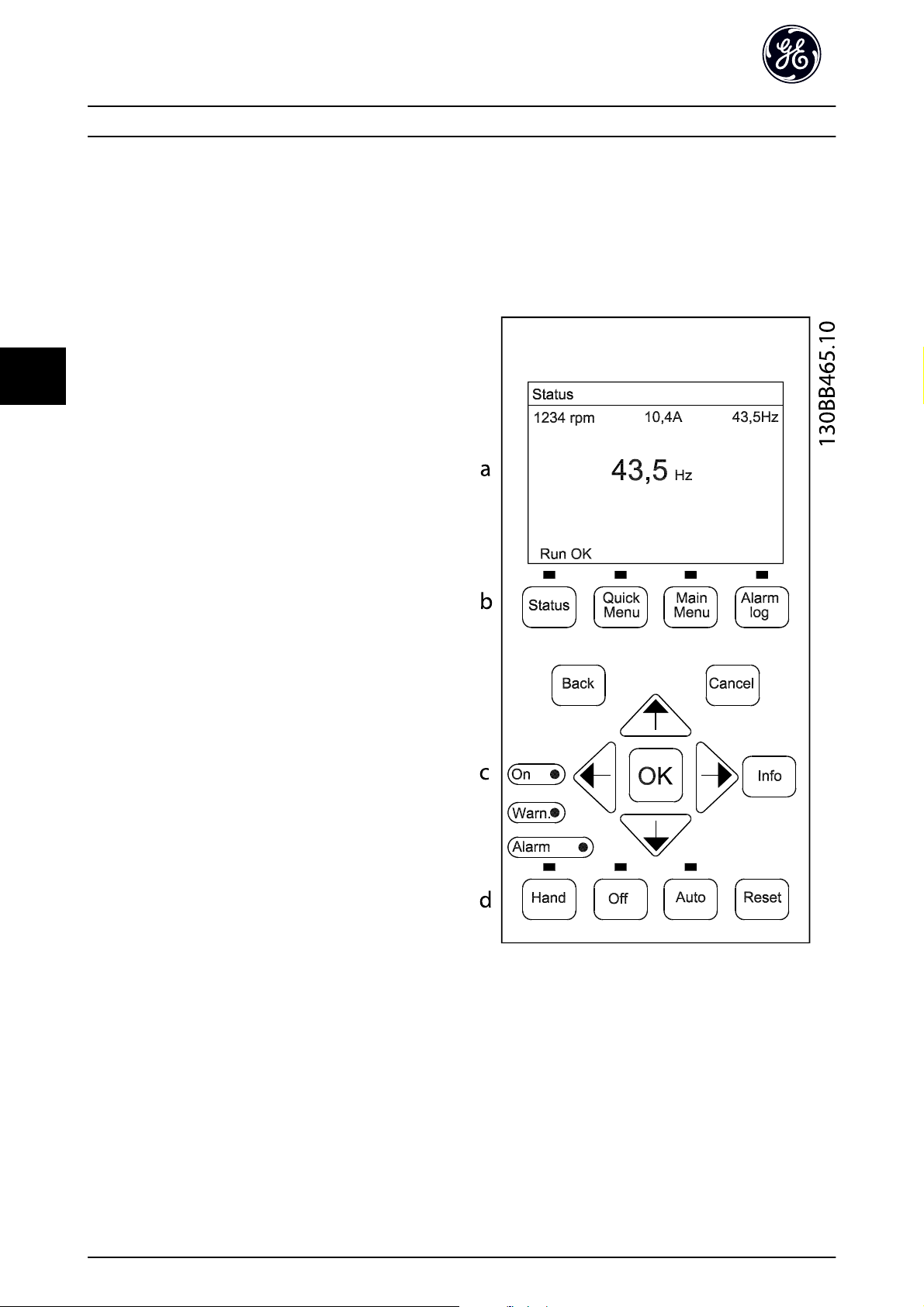
The Keypad is divided into four functional groups (see
Illustration 5.1).
20 DET-759A
Illustration 5.1 Keypad
a. Display area.
b. Display menu keys for changing the display to
show status options, programming, or error
message history.
c. Navigation keys for programming functions,
moving the display cursor, and speed control in
local operation. Also included are the status
indicator lights.
d. Operational mode keys and reset.

User Interface AF-650 GP Quick Guide
5
5.1.2 Setting Keypad Display Values
The display area is activated when the adjustable
frequency drive receives power from AC line voltage, a DC
bus terminal, or an external 24 V supply.
The information displayed on the Keypad can be
customized for user application.
Each display readout has a parameter associated
•
with it.
Options are selected in main menu K-2#
•
The adjustable frequency drive status at the
•
bottom line of the display is generated automatically and is not selectable.
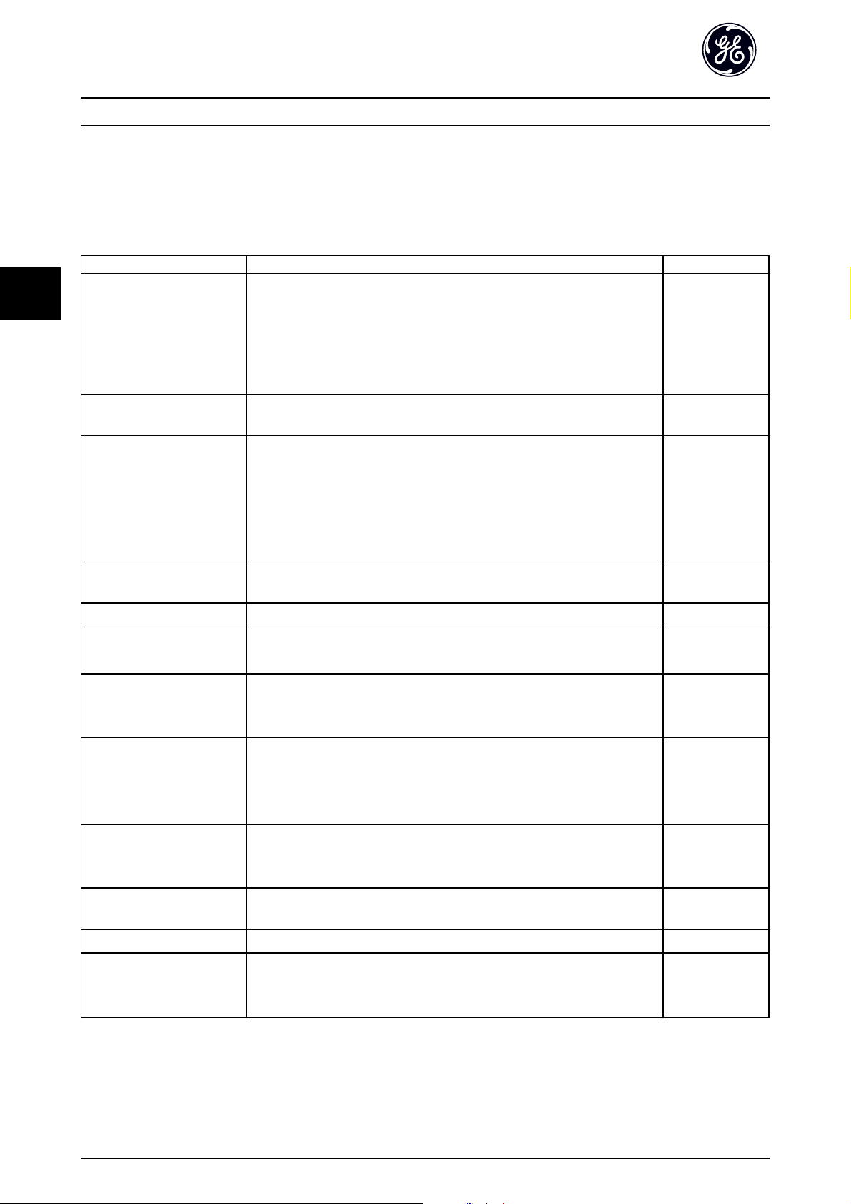
Display Parameter number Default setting
1.1 K-20 Speed [RPM]
1.2 K-21 Motor Current
1.3 K-22 Power [kW] [HP]
2 2.7 K-23 Frequency
3 K-24 Reference [%]
5.1.3 Display Menu Keys
Menu keys are used for menu access for parameter set-up,
toggling through status display modes during normal
operation, and viewing fault log data.
Key Function
Status Press to show operational information.
Press repeatedly to scroll through each
•
status display.
•
Press and hold [Status] plus [▲] or [▼] to
adjust the display brightness
The symbol in the upper right corner of the
•
display shows the direction of motor
rotation and which set-up is active. This is
not programmable.
Quick Menu Allows access to programming parameters for
initial set-up instructions and many detailed
application instructions.
Press to access Quick Start for sequenced
•
instructions to program the basic frequency
controller set up
Press to access Trending for realtime logging
•
on the keypad display.
Press to access Parameter Data Check for
•
changes in the parameter data set.
Follow the sequence of parameters as
•
presented for the function set-up
Main Menu Allows access to all programming parameters.
Press twice to access top level index.
•
Press once to return to the last location
•
accessed.
Press and hold to enter a parameter
•
number for direct access to that parameter.
Alarm Log Displays a list of current warnings, the last 10
alarms, and the maintenance log.
For details about the adjustable frequency
•
drive before it entered the alarm mode,
select the alarm number using the
navigation keys and press [OK].
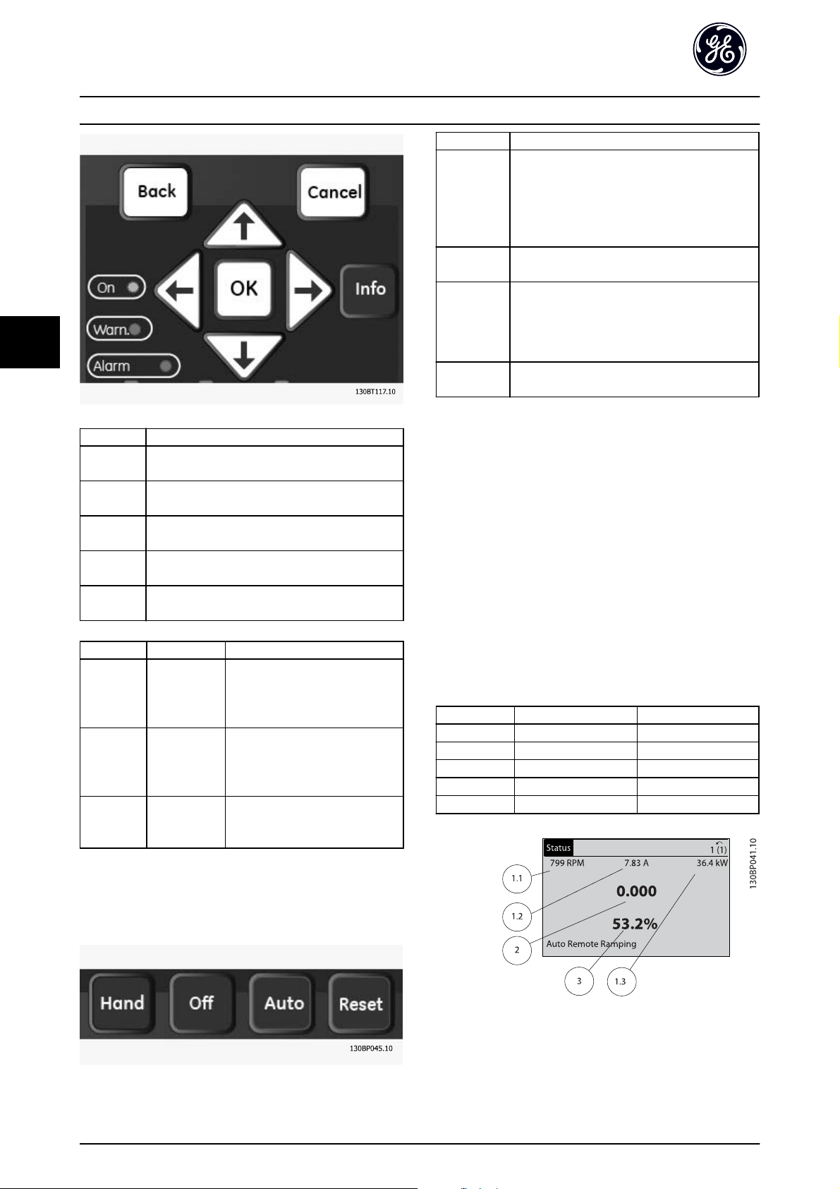
5.1.4 Navigation Keys
5
Navigation keys are used for programming functions and
moving the display cursor. The navigation keys also
provide speed control in local (hand) operation. Three
drive status indicator lights are also located in this area.
DET-759A 21
5
User Interface AF-650 GP Quick Guide
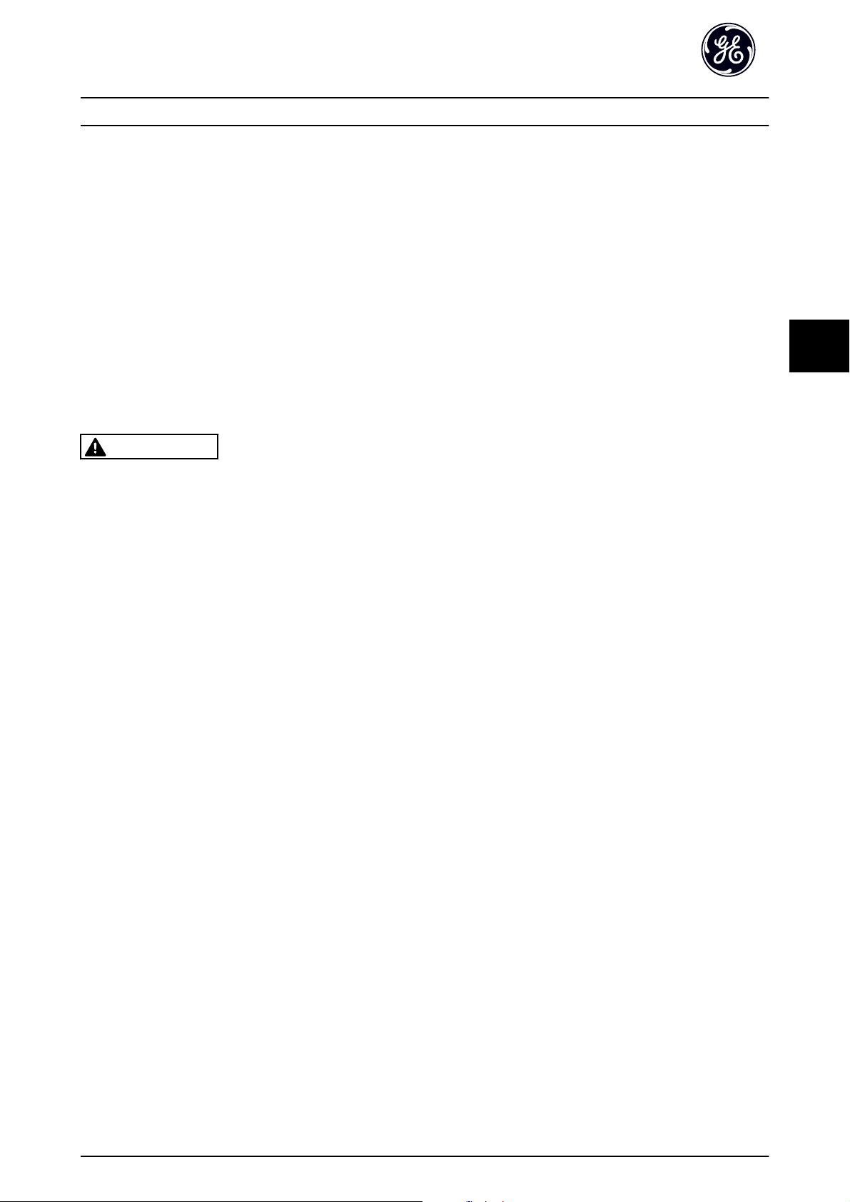
Key Function
Hand Press to start the drive in local control.
Use the navigation keys to control drive
•
speed
An external stop signal by control input or
•
serial communication overrides the local hand
Off Stops the motor but does not remove power to
the drive.
Auto Puts the system in remote operational mode.
Responds to an external start command by
•
control terminals or serial communication
Speed reference is from an external source
•
Reset Resets the drive manually after a fault has been
cleared.
Key Function
Back Reverts to the previous step or list in the menu
structure.
Cancel Cancels the last change or command as long as
the display mode has not changed.
Info Press for a definition of the function being
displayed.
Navigation
Keys
OK Use to access parameter groups or to enable a
Light Indicator Function
Green ON The ON light activates when the
Yellow WARN When warning conditions are met,
Red ALARM A fault condition causes the red
Use the four navigation arrows to move between
items in the menu.
choice.
drive receives power from AC line
voltage, a DC bus terminal, or an
external 24V supply.
the yellow WARN light comes on
and text appears in the display
area identifying the problem.
alarm light to flash and an alarm
text is displayed.
5.1.6 Setting Keypad Display Values
The display area is activated when the adjustable
frequency drive receives power from AC line voltage, a DC
bus terminal, or an external 24 V supply.
The information displayed on the Keypad can be
customized for user application.
Each display readout has a parameter associated
•
with it.
Options are selected in main menu K-2#
•
The adjustable frequency drive status at the
•
bottom line of the display is generated automatically and is not selectable.
Display Parameter number Default setting
1.1 K-20 Speed [RPM]
1.2 K-21 Motor Current
1.3 K-22 Power [kW] [HP]
2 2.7 K-23 Frequency
3 K-24 Reference [%]
5.1.5 Operation Keys
Operation keys are found at the bottom of the Keypad.
22 DET-759A
User Interface AF-650 GP Quick Guide
5
5.2 Backup and Copying Parameter Settings
Programming data is stored internally in the drive.
The data can be uploaded into the Keypad
•
memory as a storage backup
Once stored in the Keypad, the data can be
•
downloaded back into the drive
Data can also be downloaded into other
•
adjustable frequency drives by connecting the
Keypad into those units and downloading the
stored settings. (This is a quick way to program
multiple units with the same settings.)
Initialization of the drive to restore factory default
•
settings does not change data stored in the
Keypad memory
WARNING
UNINTENDED START!
When the drive is connected to AC line power, the motor
may start at any time. The drive, motor, and any driven
equipment must be in operational readiness. Failure to
comply could result in death, serious injury, equipment or
property damage.
5.3 Restoring Default Settings
CAUTION
Initialization restores the unit to factory default settings.
Any programming, motor data, localization, and
monitoring records will be lost. Uploading data to the
Keypad provides a backup prior to initialization.
Restoring the drive parameter settings back to default
values is done by initialization of the adjustable frequency
drive. Initialization can be through H-03 Restore Factory
Settings or manually.
Initialization using H-03 Restore Factory Settings
•
does not change drive data such as operating
hours, serial communication selections, personal
menu settings, fault log, alarm log, and other
monitoring functions
Using H-03 Restore Factory Settings is generally
•
recommended.
Manual initialization erases all motor,
•
programming, localization, and monitoring data
and restores factory default settings.
5
5.2.1 Uploading Data to the Keypad
1. Press [OFF] to stop the motor before uploading
or downloading data.
2. Go to K-50 Keypad Copy.
3. Press [OK].
4.
Select All to Keypad.
5. Press [OK]. A progress bar shows the uploading
progress.
6. Press [Hand] or [Auto] to return to normal
operation.
5.2.2 Downloading Data from the Keypad
1. Press [OFF] to stop the motor before uploading
or downloading data.
2. Go to K-50 Keypad Copy.
3. Press [OK].
4. Select All from Keypad.
5. Press [OK]. A progress bar shows the
downloading process.
6. Press [Hand] or [Auto] to return to normal
operation.
5.3.1 Recommended Initialization
1. Press [Main Menu] twice to access parameters.
2.
Scroll to H-03 Restore Factory Settings.
3. Press [OK].
4. Scroll to [2] Restore Factory Settings.
5. Press [OK].
6. Remove power to the unit and wait for the
display to turn off.
7. Apply power to the unit.
Default parameter settings are restored during start-up.
This may take slightly longer than normal.
8. Alarm 80 is displayed.
9. Press [Reset] to return to operation mode.
5.3.2 Manual Initialization
1. Remove power to the unit and wait for the
display to turn off.
2. Press and hold [Status], [Main Menu], and [OK] at
the same time and apply power to the unit.
Factory default parameter settings are restored during
startup. This may take slightly longer than normal.
DET-759A 23

5
User Interface AF-650 GP Quick Guide
Manual initialization does not reset the following drive
information
ID-00 Operating Hours
•
ID-03 Power Up's
•
ID-04 Over Temp's
•
ID-05 Over Volt's
•
24 DET-759A

Parameter Menu Structure AF-650 GP Quick Guide
6
H-52 Min Speed Normal Magnetizing [Hz]
H-53 Model Shift Frequency
H-54 Voltage reduction in fieldweakening
H-55 U/f Characteristic - U
H-56 U/f Characteristic - F
H-58 Flystart Test Pulses Current
H-59 Flystart Test Pulses Frequency
H-6# Load Depend. Settings
H-61 High Speed Load Compensation
H-64 Resonance Dampening
H-65 Resonance Dampening Time Constant
H-66 Min. Current at Low Speed
H-7# Adj. Warnings
H-70 Warning Current Low
H-71 Warning Current High
H-72 Warning Speed Low
H-73 Warning Speed High
H-74 Warning Reference Low
H-75 Warning Reference High
H-76 Warning Feedback Low
H-77 Warning Feedback High
H-78 Missing Motor Phase Function
H-8# Stop Adjustments
H-87 Load Type
H-88 Minimum Inertia
H-89 Maximum Inertia
H-80 Function at Stop
H-81 Min Speed for Function at Stop [RPM]
H-82 Min Speed for Function at Stop [Hz]
H-83 Precise Stop Function
H-84 Precise Stop Counter Value
Delay
H-85 Precise Stop Speed Compensation
H-9# Motor Temperature
H-95 KTY Sensor Type
H-96 KTY Thermistor Input
H-97 KTY Threshold level
AN-## Analog In / Out
AN-0# Analog I/O Mode
AN-00 Live Zero Timeout Time
AN-01 Live Zero Timeout Function
AN-1# Analog Input 53
AN-10 Terminal 53 Low Voltage
AN-11 Terminal 53 High Voltage
AN-12 Terminal 53 Low Current
AN-13 Terminal 53 High Current
AN-14 Terminal 53 Low Ref./Feedb. Value
AN-15 Terminal 53 High Ref./Feedb. Value
AN-16 Terminal 53 Filter Time Constant
AN-2# Analog Input 54
AN-20 Terminal 54 Low Voltage
AN-21 Terminal 54 High Voltage
AN-22 Terminal 54 Low Current
AN-23 Terminal 54 High Current
AN-24 Terminal 54 Low Ref./Feedb. Value
AN-25 Terminal 54 High Ref./Feedb. Value
AN-26 Terminal 54 Filter Time Constant
AN-3# Analog Input X30/11
AN-30 Terminal X30/11 Low Voltage
6
C-23 Quick Stop Decel Time
E-24 Function Relay
F-11 Motor External Fan
C-24 Quick Stop Ramp Type
C-25 Quick Stop S-ramp Ratio at Decel. Start
E-26 On Delay, Relay
E-27 Off Delay, Relay
F-12 Motor Thermistor Input
F-18 Motor Speed Low Limit [RPM]
C-26 Quick Stop S-ramp Ratio at Decel. End
E-3# X46 Digital Inputs
F-16 Motor Speed Low Limit [Hz]
C-3# Frequ. Set. 2 and 3
C-30 Frequency Command 2
E-30 Terminal X46/1 Digital Input
E-31 Terminal X46/3 Digital Input
F-17 Motor Speed High Limit [RPM]
F-15 Motor Speed High Limit [Hz]
C-34 Frequency Command 3
P-## Motor Data
E-32 Terminal X46/5 Digital Input
E-33 Terminal X46/7 Digital Input
F-2# Fundamental 2
F-24 Holding Time
P-0# Motor Data
P-07 Motor Power [kW]
P-02 Motor Power [HP]
E-34 Terminal X46/9 Digital Input
E-35 Terminal X46/11 Digital Input
E-36 Terminal X46/13 Digital Input
F-25 Start Function
F-22 Start Speed [RPM]
F-23 Start Speed [Hz]
P-03 Motor Current
P-06 Base Speed
P-05 Motor Cont. Rated Torque
E-5# I/O Mode / Add On I/O
E-51 Terminal 27 Mode
E-52 Terminal 29 Mode
F-29 Start Current
F-26 Motor Noise (Carrier Freq)
F-27 Motor Tone Random
P-04 Auto Tune
P-01 Motor Poles
E-53 Terminal X30/2 Digital Input
E-54 Terminal X30/3 Digital Input
F-28 Dead Time Compensation
F-3# Fundamental 3
P-09 Slip Compensation
P-10 Slip Compensation Time Constant
E-55 Terminal X30/4 Digital Input
E-56 Term X30/6 Digi Out (OPCGPIO)
F-37 Adv. Switching Pattern
F-38 Overmodulation
P-2# Motor Selection
P-20 Motor Construction
E-57 Term X30/7 Digi Out (OPCGPIO)
E-6# Pulse Input
F-4# Fundamental 4
F-40 Torque Limiter (Driving)
P-3# Adv. Motor Data
E-60 Term. 29 Low Frequency
F-41 Torque Limiter (Braking)
P-30 Stator Resistance (Rs)
P-31 Rotor Resistance (Rr)
E-61 Term. 29 High Frequency
E-62 Term. 29 Low Ref./Feedb. Value
F-43 Current Limit
F-5# Extended References
P-33 Stator Leakage Reactance (X1)
P-34 Rotor Leakage Reactance (X2)
P-35 Main Reactance (Xh)
P-36 Iron Loss Resistance (Rfe)
P-37 d-axis Inductance (Ld)
H-## High Perf Parameters
H-0# High Perf Operations
H-09 Start Mode
H-07 Accel/Decel Time 1 Type
H-08 Reverse Lock
H-04 Auto-Reset (Times)
H-05 Auto-Reset (Reset Interval)
H-03 Restore Factory Settings
H-2# Motor Feedback Monitoring
H-20 Motor Feedback Loss Function
H-21 Motor Feedback Speed Error
H-22 Motor Feedback Loss Timeout
H-24 Tracking Error Function
H-25 Tracking Error
H-26 Tracking Error Timeout
H-27 Tracking Error Ramping
H-28 Tracking Error Ramping Timeout
H-29 Tracking Error After Ramping Timeout
H-4# Advanced Settings
H-40 Configuration Mode
H-41 Motor Control Principle
H-42 Flux Motor Feedback Source
H-43 Torque Characteristics
H-44 Constant or Variable Torque OL
H-45 Local Mode Configuration
H-48 Clockwise Direction
H-46 Back EMF at 1000 RPM
H-47 Motor Angle Offset
H-5# Load Indep. Settings
H-50 Motor Magnetization at Zero Speed
H-51 Min Speed Normal Magnetizing [RPM]
E-63 Term. 29 High Ref./Feedb. Value
E-64 Pulse Filter Time Constant #29
E-65 Term. 33 Low Frequency
E-66 Term. 33 High Frequency
E-67 Term. 33 Low Ref./Feedb. Value
E-68 Term. 33 High Ref./Feedb. Value
E-69 Pulse Filter Time Constant #33
E-7# Pulse Output
E-70 Terminal 27 Pulse Output Variable
E-72 Pulse Output Max Freq #27
E-73 Terminal 29 Pulse Output Variable
E-75 Pulse Output Max Freq #29
E-76 Terminal X30/6 Pulse Output Variable
E-78 Pulse Output Max Freq #X30/6
E-8# 24V Encoder Input
E-80 Term 32/33 Pulses Per Revolution
E-81 Term 32/33 Encoder Direction
E-9# Bus Controlled
E-90 Digital & Relay Bus Control
E-93 Pulse Out #27 Bus Control
E-94 Pulse Out #27 Timeout Preset
E-95 Pulse Out #29 Bus Control
E-96 Pulse Out #29 Timeout Preset
E-97 Pulse Out #X30/6 Bus Control
E-98 Pulse Out #X30/6 Timeout Preset
C-## Freq Ctrl Functions
C-0# Freq Ctrl Functions
C-05 Multi-step Frequency 1 - 8
C-02 Jump Speed From [RPM]
C-01 Jump Frequency From [Hz]
C-03 Jump Speed To [RPM]
C-04 Jump Frequency To [Hz]
C-2# Jog Setup
C-20 Jog Speed [Hz]
C-21 Jog Speed [RPM]
C-22 Jog Accel/Decel Time
F-50 Reference Range
F-51 Reference/Feedback Unit
F-52 Minimum Reference
F-53 Maximum Reference
F-54 Reference Function
F-6# References
F-62 Catch up/slow-down value
F-64 Preset Relative Reference
F-68 Relative Scaling Reference Resource
F-9# Digital Potentiometer
F-90 Step Size
F-91 Accel/Decel Time
F-92 Power Restore
F-93 Maximum Limit
F-94 Minimum Limit
F-95 Accel/Decel Ramp Delay
E-## Digital In/Out
E-0# Digital Inputs
E-00 Digital I/O Mode
E-01 Terminal 18 Digital Input
E-02 Terminal 19 Digital Input
E-03 Terminal 27 Digital Input
E-04 Terminal 29 Digital Input
E-05 Terminal 32 Digital Input
E-06 Terminal 33 Digital Input
E-07 Terminal 37 Safe Stop
E-1# Additional Accel Decel Ramps
E-10 Accel Time 2
E-11 Decel Time 2
E-12 Accel Time 3
E-13 Decel Time 3
E-14 Accel Time 4
E-15 Decel Time 4
E-2# Digital Output
E-20 Terminal 27 Digital Output
E-21 Terminal 29 Digital Output
Structure
Keypad Set-up
6.1.1 Main Menu
Parameter Data Set
K-0# Keypad Basic Set.
K-01 Language
K-02 Motor Speed Unit
K-03 Regional Settings
K-04 Operating State at Power-up
K-09 Performance Monitor
K-1# Keypad Set-up Ops
K-10 Active Set-up
K-11 Edit Set-up
K-12 This Set-up Linked to
K-13 Readout: Linked Set-ups
K-14 Readout: Edit Set-ups / Channel
K-2# Keypad Display
K-20 Display Line 1.1 Small
K-21 Display Line 1.2 Small
K-22 Display Line 1.3 Small
K-23 Display Line 2 Large
K-24 Display Line 3 Large
K-25 Quick Start
K-3# Keypad Custom Readout
K-30 Unit for Custom Readout
K-31 Min Value of Custom Readout
K-32 Max Value of Custom Readout
K-37 Display Text 1
K-38 Display Text 2
K-39 Display Text 3
K-4# Keypad Buttons
K-40 [Hand] Button on Keypad
K-41 [Off] Button on Keypad
K-42 [Auto] Button on Keypad
K-43 [Reset] Button on Keypad
K-44 [Off/Reset] Key on Keypad
K-5# Copy/Save
K-50 Keypad Copy
K-51 Set-up Copy
K-6# Password Protect.
K-60 Main Menu Password
K-61 Access to Main Menu w/o Password
K-65 Quick Menu Password
K-66 Access to Quick Menu w/o Password
K-67 Bus Password Access
F-## Fundamental Params
F-0# Fundamental 0
F-05 Motor Rated Voltage
F-04 Base Frequency
F-09 Torque Boost
F-02 Operation Method
F-01 Frequency Setting 1
F-07 Accel Time 1
F-08 Decel Time 1
F-03 Max Output Frequency 1
F-1# Fundamental 1
F-10 Electronic Overload
DET-759A 25

6
Parameter Menu Structure AF-650 GP Quick Guide
EN-20 Control Instance
EN-21 Process Data Config Write
EN-22 Process Data Config Read
EN-28 Store Data Values
EN-29 Store Always
EN-3# EtherNet/IP
EN-30 Warning Parameter
EN-31 Net Reference
EN-32 Net Control
EN-33 CIP Revision
EN-34 CIP Product Code
EN-35 EDS Parameter
EN-37 COS Inhibit Timer
EN-38 COS Filter
EN-4# Modbus TCP
EN-40 Status Parameter
EN-41 Slave Message Count
EN-42 Slave Exception Message Count
EN-8# Other Ethernet Services
EN-80 FTP Server
EN-81 HTTP Server
EN-82 SMTP Service
EN-89 Transparent Socket Channel Port
EN-9# Advanced Ethernet Services
EN-90 Cable Diagnostic
EN-91 MDI-X
EN-92 IGMP Snooping
EN-93 Cable Error Length
EN-94 Broadcast Storm Protection
EN-95 Broadcast Storm Filter
EN-96 Port Mirroring
Parameter Data Check
Last 10 Changes
Since Factory Setting
Drive Information
EN-98 Interface Counters
EN-99 Media Counters
EC-## Feedback Option
EC-1# Inc. Enc. Interface
EC-10 Signal Type
EC-11 Resolution (PPR)
EC-2# Abs. Enc. Interface
EC-20 Protocol Selection
EC-21 Resolution (Positions/Rev)
EC-24 SSI Data Length
EC-25 Clock Rate
EC-26 SSI Data Format
EC-34 HIPERFACE Baud rate
EC-6# Monitoring and App.
EC-60 Feedback Direction
EC-61 Feedback Signal Monitoring
RS-## Resolver Interface
RS-50 Poles
RS-51 Input Voltage
RS-52 Input Frequency
RS-53 Transformation Ratio
RS-59 Resolver Interface
ID-0# Operating Data
ID-00 Operating Hours
DN-31 Store Data Values
O-10 Control Word Profile
SP-43 Motor Cos Phi
DN-32 Devicenet Revision
O-13 Configurable Status Word STW
SP-5# Environment
DN-33 Store Always
DN-34 DeviceNet Product Code
DN-39 Devicenet F Parameters
DN-5# DeviceNet Proc Data
PB-## Profibus
K-11 Edit Set-up
PB-00 Setpoint
PB-07 Actual Value
PB-15 PCD Write Configuration
PB-16 PCD Read Configuration
PB-18 Node Address
PB-22 Telegram Selection
PB-23 Parameters for Signals
PB-27 Parameter Edit
PB-28 Process Control
PB-44 Fault Message Counter
PB-45 Fault Code
PB-47 Fault Number
PB-52 Fault Situation Counter
PB-53 Profibus Warning Word
PB-63 Actual Baud Rate
PB-64 Device Identification
PB-65 Profile Number
PB-67 Control Word 1
PB-68 Status Word 1
PB-71 Profibus Save Data Values
PB-72 ProfibusDriveReset
PB-80 Defined Parameters (1)
PB-81 Defined Parameters (2)
PB-82 Defined Parameters (3)
PB-83 Defined Parameters (4)
PB-84 Defined Parameters (5)
PB-90 Changed Parameters (1)
PB-91 Changed Parameters (2)
PB-92 Changed Parameters (3)
PB-93 Changed parameters (4)
PB-94 Changed parameters (5)
PB-99 Profibus Revision Counter
EN-## Ethernet IP
EN-0# IP Settings
EN-00 IP Address Assignment
EN-01 IP Address
EN-02 Subnet Mask
EN-03 Default Gateway
EN-04 DHCP Server
EN-05 Lease Expires
EN-06 Name Servers
EN-07 Domain Name
EN-08 Host Name
EN-09 Physical Address
EN-1# Ethernet Link Parameters
EN-10 Link Status
EN-11 Link Duration
EN-12 Auto Negotiation
EN-13 Link Speed
EN-14 Link Duplex
EN-2# Process Data
O-14 Configurable Control Word CTW
O-3# Drive Port Settings
O-30 Protocol
O-31 Address
O-32 Drive Port Baud Rate
O-33 Drive port parity
O-34 Estimated cycle time
O-35 Minimum Response Delay
O-36 Max Response Delay
O-37 Max Inter-Char Delay
O-4# Drive MC Port Set.
O-40 Telegram Selection
O-41 Parameters for Signals
O-42 PCD Write Configuration
O-43 PCD Read Configuration
O-5# Digital / Bus
O-50 Coasting Select
O-51 Quick Stop Select
O-52 DC Brake Select
O-53 Start Select
O-54 Reversing Select
O-55 Set-up Select
O-56 Preset Reference Select
O-57 Profidrive OFF2 Select
O-58 Profidrive OFF3 Select
O-8# Drive Port Diagns
O-80 Bus Message Count
O-81 Bus Error Count
O-82 Slave Messages Rcvd
O-83 Slave Error Count
O-9# Bus Jog / Feedback
O-90 Bus Jog 1 Speed
O-91 Bus Jog 2 Speed
DN-## Devicenet serial communication bus
DN-0# Common Settings
DN-00 DeviceNet Protocol
DN-01 Baud Rate Select
DN-02 MAC ID
DN-05 Readout Transmit Error Counter
DN-06 Readout Receive Error Counter
DN-07 Readout Bus Off Counter
DN-1# DeviceNet
DN-10 Process Data Type Selection
DN-11 Process Data Config Write
DN-12 Process Data Config Read
DN-13 Warning Parameter
DN-14 Net Reference
DN-15 Net Control
DN-18 internal_process_data_config_write
DN-19 internal_process_data_config_read
DN-2# COS Filters
DN-20 COS Filter 1
DN-21 COS Filter 2
DN-22 COS Filter 3
DN-23 COS Filter 4
DN-3# Parameter Access
DN-30 Array Index
Start
End
Start
End
Start
End
Start
End
Start
End
Start
End
Start
End
Start
End
SP-50 RFI Filter
SP-51 DC Link Compensation
SP-52 Fan Operation
SP-53 Fan Monitor
SP-55 Output Filter
SP-56 Capacitance Output Filter
SP-57 Inductance Output Filter
SP-59 Actual Number of Inverter Units
SP-6# Automatic Derate
SP-63 Option Supplied by External 24VDC
SP-7# Add ACC/DEC settings
SP-71 Accel Time 1 S-ramp Ratio at Accel.
SP-72 Accel Time 1 S-ramp Ratio at Accel.
SP-73 Decel Time 1 S-ramp Ratio at Decel.
SP-74 Decel Time 1 S-ramp Ratio at Decel.
SP-76 Accel/Decel Time 2 Type
SP-79 Accel Time 2 S-ramp Ratio at Accel.
SP-80 Accel Time 2 S-ramp Ratio at Accel.
SP-81 Decel Time 2 S-ramp Ratio at Decel.
SP-82 Decel Time 2 S-ramp Ratio at Decel.
SP-84 Accel/Decel Ramp 3 Type
SP-87 Accel Time 3 S-ramp Ratio at Accel.
SP-88 Accel Time 3 S-ramp Ratio at Accel.
SP-89 Decel Time 3 S-ramp Ratio at Decel.
SP-90 Decel Time 3 S-ramp Ratio at Decel.
SP-92 Accel/Decel Ramp 4 Type
SP-95 Accel Time 4 S-ramp Ratio at Accel.
SP-96 Accel Time 4 S-ramp Ratio at Accel.
SP-97 Decel Time 4 S-ramp Ratio at Decel.
SP-98 Decel Time 4 S-ramp Ratio at Decel.
O-## Options / Comms
O-0# General Settings
O-01 Control Site
O-02 Control Word Source
O-03 Control Word Timeout Time
O-04 Control Word Timeout Function
O-05 End-of-Timeout Function
O-06 Reset Control Word Timeout
O-07 Diagnosis Trigger
O-08 Readout Filtering
O-1# Control Settings
AN-31 Terminal X30/11 High Voltage
AN-34 Term. X30/11 Low Ref./Feedb. Value
AN-35 Term. X30/11 High Ref./Feedb. Value
AN-36 Term. X30/11 Filter Time Constant
AN-4# Analog Input X30/12
AN-40 Terminal X30/12 Low Voltage
AN-41 Terminal X30/12 High Voltage
AN-44 Term. X30/12 Low Ref./Feedb. Value
AN-45 Term. X30/12 High Ref./Feedb. Value
AN-46 Term. X30/12 Filter Time Constant
AN-5# Analog Output 42
AN-50 Terminal 42 Output
AN-51 Terminal 42 Output Min Scale
AN-52 Terminal 42 Output Max Scale
AN-53 Terminal 42 Output Bus Control
AN-54 Terminal 42 Output Timeout Preset
AN-55 Terminal 42 Output Filter
AN-6# Analog Output X30/8
AN-60 Terminal X30/8 Output
AN-61 Terminal X30/8 Min. Scale
AN-62 Terminal X30/8 Max. Scale
AN-63 Terminal X30/8 Bus Control
AN-64 Terminal X30/8 Output Timeout Preset
AN-7# Analog Output X45/1
AN-70 Terminal X45/1 Output
AN-71 Terminal X45/1 Min. Scale
AN-72 Terminal X45/1 Max. Scale
AN-73 Terminal X45/1 Bus Control
AN-74 Terminal X45/1 Output Timeout Preset
AN-8# Analog Output X45/3
AN-80 Terminal X45/3 Output
26 DET-759A
AN-81 Terminal X45/3 Min. Scale
AN-82 Terminal X45/3 Max. Scale
AN-83 Terminal X45/3 Bus Control
AN-84 Terminal X45/3 Output Timeout Preset
SP-## Special Functions
SP-0# Fault Settings
SP-00 Fault Level
SP-1# Line On/Off
SP-10 Line failure
SP-11 Line Voltage at Input Fault
SP-12 Function at Line Imbalance
SP-13 Line Failure Step Factor
SP-2# Reset Functions
SP-23 Typecode Setting
SP-24 Trip Delay at Current Limit
SP-25 Trip Delay at Torque Limit
SP-26 Trip Delay at Drive Fault
SP-28 Production Settings
SP-29 Service Code
SP-3# Current Limit Ctrl.
SP-30 Current Limit Cntrl, Proportional Gain
SP-31 Current Limit Cntrl, Integration Time
SP-32 Current Lim Ctrl, Filter Time
SP-35 Stall Protection
SP-4# Energy Savings
SP-40 VT Level
SP-41 Energy Savings Min. Magnetization
SP-42 Energy Savings Min. Frequency

Parameter Menu Structure AF-650 GP Quick Guide
6
SF-09 Wobble Random Function
SF-10 Wobble Ratio
SF-11 Wobble Random Ratio Max.
SF-12 Wobble Random Ratio Min.
SF-19 Wobble Delta Freq. Scaled
SF-2# Adv. Start Adjust
SF-20 High Starting Torque Time [s]
SF-21 High Starting Torque Current [%]
SF-22 Locked Rotor Protection
SF-23 Locked Rotor Detection Time [s]
PI-## PID Controls
PI-0# Speed PID Control
PI-00 Speed PID Feedback Source
PI-03 Speed PID Integral Time
PI-04 Speed PID Differentiation Time
PI-05 Speed PID Diff. Gain Limit
PI-06 Speed PID Low-pass Filter Time
PI-07 Speed PID Feedback Gear Ratio
PI-08 Speed PID Feed Forward Factor
PI-02 Speed PID Proportional Gain
PI-1# Torque PI Ctrl.
PI-12 Torque PI Proportional Gain
PI-13 Torque PI Integration Time
PI-2# Process PID Feedback
PI-20 Process CL Feedback 1 Resource
PI-22 Process CL Feedback 2 Resource
PI-3# Process PID Control
PI-30 Process PID Normal/ Inverse Control
PI-31 Process PID Anti Windup
PI-32 Process PID Start Speed
PI-33 Process PID Proportional Gain
PI-34 Process PID Integral Time
PI-35 Process PID Differentiation Time
PI-36 Process PID Diff. Gain Limit
PI-38 Process PID Feed Forward Factor
PI-39 On Reference Bandwidth
PI-4# Adv. Process PID I
PI-40 Process PID I-part Reset
PI-41 Process PID Output Neg. Clamp
PI-42 Process PID Output Pos. Clamp
PI-43 Process PID Gain Scale at Min. Ref.
PI-44 Process PID Gain Scale at Max. Ref.
PI-45 Process PID Feed Fwd Resource
6
Ctrl.
SF-00 Wobble Mode
SF-01 Wobble Delta Frequency [Hz]
SF-02 Wobble Delta Frequency [%]
SF-03 Wobble Delta Freq. Scaling Resource
SF-04 Wobble Jump Frequency [Hz]
SF-05 Wobble Jump Frequency [%]
SF-06 Wobble Jump Time
SF-07 Wobble Sequence Time
PI-46 Process PID Feed Fwd Normal/ Inv.
PI-49 Process PID Output Normal/ Inv. Ctrl.
PI-5# Adv. Process PID II
PI-50 Process PID Extended PID
PI-51 Process PID Feed Fwd Gain
PI-52 Process PID Feed Fwd Ramp-up
PI-53 Process PID Feed Fwd Ramp-down
PI-56 Process PID Ref. Filter Time
PI-57 Process PID Fb. Filter Time
PI-6# PID Readouts
PI-60 Process PID Error
PI-61 Process PID Output
PI-62 Process PID Clamped Output
PI-63 Process PID Gain Scaled Output
SF-## Special Features
SF-0# Wobbler
SF-08 Wobble Up/Down Time
DR-86 Drive Port REF 1
99-30 internal_ProfibusPCD_Config_Write
99-31 internal_ProfibusPCD_Config_Read
DR-1# Motor Status
DR-10 Power [kW]
DR-11 Power [hp]
DR-9# Diagnosis Readouts
DR-12 Motor Voltage
DR-90 Alarm Word
DR-91 Alarm Word 2
DR-13 Frequency
DR-14 Motor Current
DR-92 Warning Word
DR-15 Frequency [%]
DR-93 Warning Word 2
DR-16 Torque [Nm]
Adv Param Data Set
DR-94 Ext. Status Word
DR-17 Speed [RPM]
DR-18 Motor Thermal
LC-## Logic Controller
DR-19 KTY sensor temperature
LC-0# LC Settings
LC-00 Logic Controller Mode
DR-20 Motor Angle
DR-21 Torque [%] High Res.
LC-01 Start Event
DR-22 Torque [%]
LC-02 Stop Event
DR-25 Torque [Nm] High
LC-03 Reset Logic Controller
DR-3# Drive Status
LC-1# Comparators
DR-30 DC Link Voltage
LC-10 Comparator Operand
DR-32 Brake Energy /s
LC-11 Comparator Operator
DR-33 Brake Energy /2 min
LC-12 Comparator Value
DR-34 Heatsink Temp.
LC-2# Timers
DR-35 Drive Thermal
LC-20 Logic Controller Timer
LC-4# Logic Rules
DR-36 Drive Nominal Current
DR-37 Drive Max. Current
LC-40 Logic Rule Boolean 1
LC-41 Logic Rule Operator 1
LC-42 Logic Rule Boolean 2
LC-43 Logic Rule Operator 2
LC-44 Logic Rule Boolean 3
LC-5# States
LC-51 Logic Controller Event
LC-52 Logic Controller Action
B-## Braking Functions
B-0# DC Brake
B-00 DC Hold Current
B-01 DC Brake Current
B-02 DC Braking Time
B-03 DC Brake Cut-in Speed [RPM]
B-04 DC Brake Cut-in Speed [Hz]
B-05 Maximum Reference
B-1# Brake Energy Funct.
B-10 Brake Function
B-12 Braking energy (kW)
B-13 Braking Thermal Overload
B-15 Brake Check
B-16 AC brake Max. Current
B-17 Over-voltage Control
B-18 Brake Check Condition
B-19 Over-voltage Gain
B-11 Brake Resistor (ohm)
B-2# Mechanical Brake
B-20 Release Brake Current
B-21 Activate Brake Speed [RPM]
B-22 Activate Brake Speed [Hz]
B-23 Activate Brake Delay
B-24 Stop Delay
B-25 Brake Release Time
B-26 Torque Ref
B-27 Torque Ramp Time
B-28 Gain Boost Factor
DR-38 Logic Controller State
DR-39 Control Card Temp.
DR-40 Trending Buffer Full
DR-41 Keypad Bottom Statusline
DR-49 Current Fault Source
DR-5# Ref. & Feedb.
DR-50 External Reference
DR-51 Pulse Reference
DR-52 Feedback [Unit]
DR-53 Digi Pot Reference
DR-6# Inputs & Outputs
DR-60 Digital Input
DR-61 Terminal 53 Switch Setting
DR-62 Analog Input 53
DR-63 Terminal 54 Switch Setting
DR-64 Analog Input 54
DR-65 Analog Output 42 [mA]
DR-66 Digital Output [bin]
DR-67 Freq. Input #29 [Hz]
DR-68 Freq. Input #33 [Hz]
DR-69 Pulse Output #27 [Hz]
DR-70 Pulse Output #29 [Hz]
DR-71 Relay Output [bin]
DR-72 Counter A
DR-73 Counter B
DR-74 Prec. Stop Counter
DR-75 Analog In X30/11
DR-76 Analog In X30/12
DR-77 Analog Out X30/8 [mA]
DR-78 Analog Out X45/1 [mA]
DR-79 Analog Out X45/3 [mA]
DR-8# Serial communication bus & Drive Port
DR-80 Serial communication bus CTW 1
DR-82 Serial communication bus REF 1
DR-84 Comm. Option STW
DR-85 Drive Port CTW 1
Data Readouts
ID-01 Running Hours
ID-02 kWh Counter
ID-03 Power-ups
ID-04 Over Temps
ID-05 Over Volts
ID-06 Reset kWh Counter
ID-07 Reset Running Hours Counter
ID-1# Data Trending Settings
ID-10 Trending Source
ID-11 Trending Interval
ID-12 Trigger Event
ID-13 Trending Mode
ID-14 Samples Before Trigger
ID-2# Historic Log
ID-20 Historic Log: Event
ID-21 Historic Log: Value
ID-22 Historic Log: Time
ID-3# Alarm Log
ID-30 Fault Log: Error Code
ID-31 Fault Log: Value
ID-32 Fault Log: Time
ID-4# Drive Identification
ID-40 Drive Type
ID-41 Power Section
ID-42 Voltage
ID-43 Software Version
ID-46 GE Product No.
ID-47 Power Card Ordering No.
ID-48 Keypad ID Number
ID-49 SW ID Control Card
ID-50 SW ID Power Card
ID-51 Drive Serial Number
ID-53 Power Card Serial Number
ID-6# Option Ident
ID-60 Option Mounted
ID-61 Option SW Version
ID-62 Option Ordering No
ID-63 Option Serial No
ID-70 Option in Slot A
ID-71 Slot A Option SW Version
ID-72 Option in Slot B
ID-73 Slot B Option SW Version
ID-74 Option in Slot C1
ID-75 Slot C0 Option SW Version
ID-76 Option in Slot C2
ID-77 Slot C1 Option SW Version
ID-9# Parameter Info
ID-92 Defined Parameters
ID-93 Modified Parameters
ID-98 Drive Identification
ID-99 Parameter Metadata
DR-0# General Status
DR-00 Control Word
DR-01 Reference [Unit]
DR-02 Reference %
DR-03 Status Word
DR-05 Main Actual Value [%]
DR-09 Custom Readout
DET-759A 27

6
Parameter Menu Structure AF-650 GP Quick Guide
6.2 Remote Programming with DCT-10 Setup Software
GE has a software program available for developing,
storing, and transferring drive programming. The DCT-10
allows the user to connect a PC to the drive and perform
live programming rather than using the Keypad.
Additionally, all drive programming can be done offline
and simply downloaded to thedrive. Or the entire drive
profile can be loaded onto the PC for backup storage or
analysis.
The USB connector or RS-485 terminal are available for
connecting to the drive.
For more details, please go to www.geelectrical.com/drives.
28 DET-759A

Warnings and Alarm AF-650 GP Quick Guide
7
7 Warnings and Alarm
7.1 System Monitoring
The drive monitors the condition of its input power,
output, and motor factors as well as other system
performance indicators. A warning or alarm may not
necessarily indicate a problem internal to the drive itself. In
many cases, it indicates failure conditions from input
voltage, motor load or temperature, external signals, or
other areas monitored by the adjustable frequency drive’s
internal logic. Be sure to investigate those areas exterior to
the drive as indicated in the alarm or warning.
7.2 Warning and Alarm Types
Warnings
A warning is issued when an alarm condition is impending
or when an abnormal operating condition is present and
may result in the drive issuing an alarm. A warning clears
by itself when the abnormal condition is removed.
Alarms
Trip
An alarm is issued when the drive is tripped, that is, the
drive suspends operation to prevent drive or system
damage. The motor will coast to a stop. The drive logic
will continue to operate and monitor the drive status. After
the fault condition is remedied, the drive can be reset. It
will then be ready to start operation again.
A trip can be reset in any of 4 ways:
Press [RESET] on the Keypad
•
Digital reset input command
•
Serial communication reset input command
•
Auto reset
•
Trip lock
An alarm that causes the drive to trip-lock requires that
input power be cycled. The motor will coast to a stop. The
drive logic will continue to operate and monitor the drive
status. Remove input power to the drive and correct the
cause of the fault, then restore power. This action puts the
drive into a trip condition as described above and may be
reset in any of those four ways.
7.3 Warning and Alarm Displays
An alarm or trip lock alarm will flash on display along with
the alarm number.
7
In addition to the text and alarm code on the drive
display, there are three status indicator lights.
Warn. LED Alarm LED
Warning ON OFF
Alarm OFF ON (Flashing)
Trip Lock ON ON (Flashing)
DET-759A 29
 Loading...