

Page 1
REQUIRED TOOLS AND ACCESSORIES FOR INSTALLATION
■ 2 Adjustable wrenches
■ Pipe cutter
■ Ruler or tape measure
■ Cordless drill
■ File
■ Emery paper
■ Screwdriver
Optional accessories are available (Visa, MasterCard or Discover cards accepted)
by visiting our Website at ge.com or from Parts and Accessories, call
800.626.2002 (U.S.) or 800.663.6060 (Canada).
CONTENTS INCLUDED WITH PRODUCT
■ Filter system (filter, head and canister)
■ Product literature
■ Canister wrench
■ Timer and batteries
■ Mounting bracket
■ Four 5/16″ Hex-head screws and four 5/16″ Hex washer-head
screws
■ 2 sets of fittings, ferrule and nut to connect 1″ female NPTF
threads on filter housing to 3/4″ copper plumbing
■ 2 UL-approved grounding clamps and a #6 AWG grounding wire
■ White sealing tape
■ FXHTC Chlorine: Taste and Odor filter cartridge
1
GE SmartWater
™
INSTALLATION INSTRUCTIONS
Heavy Duty Water Filtration System—GNWH38F
SAFETY PRECAUTIONS
■ Check with your state and local public works department for
plumbing and sanitation codes. You must follow these guidelines
as you install the Heavy Duty Water Filtration System. Using a
qualified installer is recommended.
■ Be sure the water supply conforms with the
Performance Data
.
If the water supply conditions are unknown, contact your
municipal water company.
WARNING:
Do not use with water that is
microbiologically unsafe or of unknown quality without
adequate disinfection before or after the system.
■ It is highly recommended that a water shut-off valve be placed
directly upstream of your household filter.
■
Check with your local public works department for plumbing codes.
You must follow their guides as you install the Heavy Duty Water
Filtration System.
■
Use the Heavy Duty Water Filtration System on a potable, safe-todrink, home COLD water supply only. The filter cartridge will not
purify water or make unsafe water safe to drink. DO NOT use on
HOT water (100°F max).
■
Protect the Heavy Duty Water Filtration System and piping from
freezing. Water freezing in the system will damage it.
■
Your Heavy Duty Water Filtration System will withstand up to
100 psi water pressure. If your house water supply pressure is
higher than 100 psi during the day (it may reach higher levels
at night), install a pressure reducing valve before the system
is installed.
■ Do not install on
HOT WATER
. The temperature of the water
supply to the Heavy Duty Water Filtration System must be
between the minimum of 40°F and the maximum of 100°F.
See the
Filter Cartridge Life
section.
■
Do not
install the Heavy Duty Water Filtration System using
copper solder fittings. The heat from the soldering process
will damage the unit.
■ If making a soldered copper installation, do all sweat soldering
before connecting pipes to the system. Torch heat will damage
plastic parts.
WARNING:
Discard all unused parts and packaging
material after installation. Small parts remaining after installation
could be a choke hazard.
■
Do not
install filter in an outside location or anywhere it will be
exposed to sunlight.
PROPER INSTALLATION
This Heavy Duty Water Filtration System must be properly installed and located in accordance with the Installation Instructions
before it is used.
184D1064P001 (01--08 JR) 49-50125-2
ge.com
GENERAL ELECTRIC COMPANY, Appliance Park, Louisville, KY 40225
GNWH38F is tested and certified by NSF International
against NSF/ANSI Standard 42 with cartridge FXHTC
for the reduction of Chlorine: Taste and Odor.
Page 2
2
Filter Cartridge Replacement
You should change your filter when the water flow is noticeably reduced or at least every 3 months.
Turn off water to filter. Water must be shut off from
an upstream valve.
Press the red pressure release button to release
pressure.
Unscrew the filter canister and discard used filter.
Wash the filter canister with mild soap and water.
Do not
use harsh cleaners or hot water.
Inspect the filter canister O-ring. Make sure it is
lightly lubricated with clean food grade silicone
grease (silicone grease is available through GE
Parts and Service: 1.800.626.2002, part number
WS60X10005). Be sure the o-ring is seated in the
groove. It is recommended that you replace the
O-ring if it is damaged.
Place a new filter cartridge into the canister,
making sure it is centered and completely seated
on the bottom seal.
Reinstall the filter canister to the unit. Use the
canister wrench to tighten the canister. DO NOT
OVERTIGHTEN.
Slowly turn on water to the filter by using the
upstream shut-off valve.
Press the red pressure release button to remove
trapped air.
After installation, flush the cartridge for
10 minutes, wait one hour, then flush again
for 10 minutes before using the water.
9
8
7
6
5
4
3
2
1
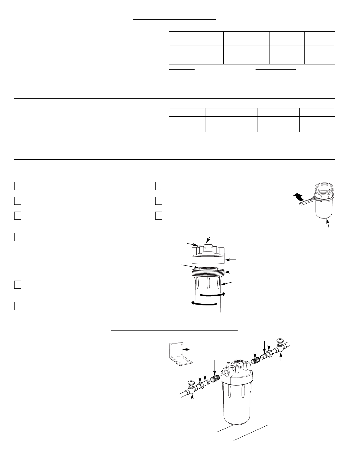
Installation Overview
NOTE: Be sure to allow a minimum space of 11⁄
2
″–2″
under
the filter for removing the sump to change the cartridge.
Turn canister wrench
clockwise to remove
Canister
Turn
clockwise
to remove
canister
Turn
counterclockwise
to tighten
Red pressure
release button
Filter
cartridge
O-ring seal
Filter canister
Head
STEP-BY-STEP INSTALLATION INSTRUCTIONS
Recommended
shut-off valve
Recommended
shut-off valve
Fitting
Ferrule
Hex nut
Fitting
Ferrule
Hex nut
1
1
⁄2 ″–2″
Typical installation
Remote timer
Mounting
bracket
CARTRIDGE SPECIFICATIONS
Influent Challenge Reduction Average
Substance Concentration Requirements Reduction
Standard 42
Chlorine: Taste and Odor 2.0 mg/L ±10% ≥50% 95.5%
Performance Data
This system has been tested according to NSF/ANSI 42
for the reduction of the substances listed below. The
concentration of the indicated substances in water
entering the system was reduced to a concentration
less than or equal to the permissible limit for water
leaving the system, as specified in NSF/ANSI 42.
FXHTC Cartridge
Test Conditions
Flow Rate: 3 gpm (11.4 Lpm)
pH: 7.5±1
Inlet Pressure: 60 PSI (4.1 bar)
Temperature: 68°F ± 5°F (19.8°C ± 2.5°C)
Operating Requirements
Pressure: 30–125 psi (2.1–6.9 bar)
Turbidity: 5 NTU Max.
Temperature: 40°F–100°F (4.4°C–37.7°C)
Capacity: 5,000 gallons (18,927L) or 3 months
Testing was performed under standard laboratory conditions, actual performance may vary.
GE Model Function Life Construction
FXHSC Sediment* 3 months/ Pleated
30 Micron* 24,000 gallons
Additional Replacement Filter
FXHSC Filter could be used as a replacement filter.
FXHSC Cartridge
Operating Guidelines
Minimum–Maximum Supply Water Pressure: 20–125 psi
Minimum–Maximum Supply Water Temperatures: 40°F–100°F
*Based on manufacturer’s internal testing.
Page 3
3
STEP-BY-STEP INSTALLATION INSTRUCTIONS (cont.)
Select Location
Select a location for the filter that is:
■ protected from freezing.
■ not exposed to direct sunlight.
It is recommended that a shut-off valve be placed on both sides of the filter.
It is recommended that a mounting bracket be used.
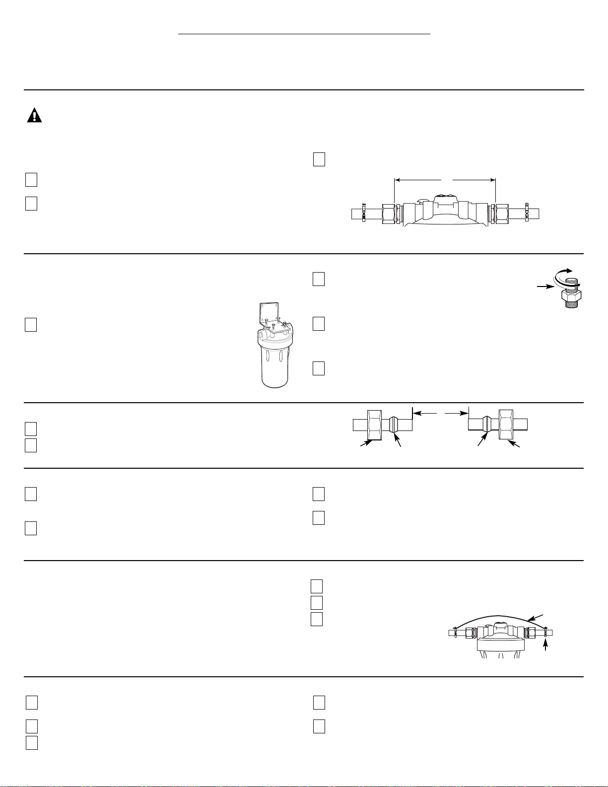
Install Mounting Bracket and Fittings
Instructions are for installing fittings supplied with the filter system or
similar fittings onto copper plumbing. If the unit is to be installed on
any other type of tubing (plastic, PVC, galvanized), consult a
qualified plumber for additional hardware.
Attach heavy duty mounting bracket to head assembly
with four hex-head screws as shown in illustration.
Failure to use the bracket may result in a leak over time.
The bracket can be used as a template for marking the
location of the mounting screws.
Apply 4 or 5 wraps of white sealing tape, in a
clockwise direction, to the pipe threads of each
fitting.
DO NOT
use joint compound on any parts
connecting to filter system.
Assemble fitting to the inlet and outlet of the head. Start each
fitting by hand to make sure they don’t cross thread. Use an
adjustable wrench to tighten fittings.
DO NOT OVERTIGHTEN.
About 1–2 thread(s) should remain visible.
Use four hex washer-head screws to mount bracket to the wall firmly.
Use proper anchors on wall. Anchors are
NOT
included.
4
3
2
1
Cut Water Line
WARNING:
A copper or galvanized cold water pipe may
be used to ground electrical outlets in the home. Failure to maintain this
ground path may result in an electric shock hazard. If the cold water
pipe is used to ground electrical outlets, please refer to the
Installing the
Ground Wire
section before cutting the pipe.
Turn off the water supply and open a nearby faucet to drain the
water out of pipes.
Using a tape measure or ruler, measure the distance “D” as shown.
■
NOTE:
It is recommended that the shut-off valve be placed before and
after the filter as shown in the
Installation Overview
illustration.
■ Select a secure location surface to install filter and mounting bracket.
The location should align the filter system with inlet and outlet pipe
and should not cause the pipes to bend or damage. Mark the distance
“D” on the pipe. D is about 7
3
⁄4″.
Using a pipe cutter, cut pipe. Sand (file) cut ends of pipe to assure
that they are square and smooth.
■
NOTE:
Have a bucket and towel available to collect excess water.
3
2
1
Installing the Unit
Align filter assembly with pipe ends making certain that the
incoming
water supply is going into the filter opening marked “IN”. It may be
necessary to spread the pipe ends apart to install filter assembly.
Using two adjustable wrenches, hold incoming fitting securely with
one wrench and tighten nut with second wrench. Repeat this
procedure for outgoing fitting.
If mounting bracket is not used, support the water pipe on either
side of the filter unit.
Install a filter and tighten canister to seal (see filter cartridge
replacement section).
4
3
2
1
Final Check
Install filter, if not already done (see
Filter Cartridge Replacement
Section).
Slowly turn on water supply.
Check entire system for leaks.
If leaking from fittings, shut off water flow and tighten or reseal
fittings. If leaking from the canister, tighten canister with a wrench.
After installation, flush the cartridge for 10 minutes, wait one hour,
then flush again for 10 minutes before using the water.
5
4
3
2
1
White
sealing
tape
Attach Fittings to Water Line
Slip a compression nut onto each pipe.
Next, slip the brass ferrule onto each pipe.
2
1
Hex Nut
Brass ferrule
Hex Nut
Brass ferrule
D
Installing the Ground Wire
NOTE:
If your house plumbing is plastic, it would not be used as a
grounding path, and this step should be skipped.
IMPORTANT:
A copper or galvanized house cold water pipe is often used
to ground electrical outlets in the home.
Grounding protects you from
electrical shock.
The water filter system may have broken this ground
path. To restore connection, install the included 6-gauge copper wire
across the filter, tightly clamped using the included UL approved
1/2″–1″bronze grounding clamps at both ends as shown.
Clean copper pipe and ends of wire with emery paper.
Attach bronze clamps to pipe. Tighten screws.
Attach wire to clamps as
shown. Tighten screws firmly
to the stripped end of the
copper wire.
3
2
1
Clamp
Ground wire
D
Page 4

4
Ref. No. Part No. Part Description
001 HDKIT Grounding Clamps and Wire 1
001 HDKIT
3
⁄4″ Copper Tube Fittings 1
002 HDCAP Head 1
003 WHTIMER Timer 1
004 HDRING O-Ring 1
005 HDSMP Canister 1
006 HDWRNCH Canister Wrench 1
007 FXHTC Filter Element—Carbon Filter 1
FXHSC Filter Element—Pleated
008 HDBRKT Mounting Bracket 1
999 49-50125-2 PM Installation Instructions 1
To obtain replacement parts, call toll-free 800.626.2002 (U.S.),
800.663.6060 (Canada–English), 800.361.3869 (Canada–French).
Timer Installation and Reset Instructions
Timer cap
Timer seat
Timer battery installation and change
Insert coin or screwdriver in the slot between timer
cap and base. Gently pry them open and separate
timer base from cap. Install or change 2 new AAA
1.5 volt batteries. After having the batteries in place,
line up the base and cap and snap them back
together.
It is recommended to change the batteries at least
every 2 filter changes (6 months).
Do not mix old and new batteries. Do not mix
alkaline, standard (carbon-zinc) or rechargeable
(ni-cad, ni-mh, etc.) batteries.
Installation of timer
Hold the timer body in the center and gently push
timer to its seat at the top of the head. Or use the
magnetic timer body to attach it in a remote location
for easy viewing.
Timer reset and application
After new batteries are installed or filter is changed,
push and hold the timer blue reset button for
approximately 5 seconds. Release the reset button after
the light flashes 5 times. The light will flash again in
90 days to remind you that it is time to change the filter.
Blue reset button
008
PARTS LIST
003
002
004
005
006
999
007
001
001
2 AAA
batteries
Timer base
Head
Page 5

5
BEFORE YOU CALL FOR SERVICE…
Problem Possible Causes What To Do
Water contains tiny
New filter cartridges contain • Turn on a water faucet and allow these harmless carbon particles to
black particles
activated carbon, which is purge from the cartridge. Turn off the faucet when the water is clear.
a harmless black powder.
Water has air bubbles
Air in system after installation. • Will go away after water runs for a while.
and is cloudy
Indicator light on the
Three months usage has occurred. • Replace filter cartridge and batteries in the timer.
timer is flashing
This is the maximum life of the
• Reset timer by holding down the reset button for 5 seconds.
filter cartridges.
Indicator light on the
Timer operating normally. • Light flashed 5 times when reset. It will not flash again until 3 months
timer is not working
have passed.
• No action required.
Batteries may need to be • Observe orientation markings on the holder and install correctly.
replaced or they may have been Replace batteries if they are old.
installed incorrectly.
Timer not reset
Reset button has built-in time delay. • Reset timer by holding down reset button for 5 seconds.
Chlorine taste and /or
The filter cartridge is no • Replace FXHTC filter cartridge.
odor in the product water
longer removing chlorine
from the water supply.
FXHSC Filter (pleated paper) is • If chlorine reduction is desired, change to FXHTC filter cartridge.
installed, which does not remove
chlorine.
Fittings are leaking
Not enough sealing tape • Unscrew fitting from head and remove old sealing tape. Add new sealing
between fitting and head
on fittings. tape to the fitting.
Fitting has become loose. • Install mounting bracket if not used.
• Tighten fittings with wrench.
Water dispenses
The filter has been installed • A three-month change-out period is recommended.
very slowly
for too long. Replace filter cartridge.
The filter cartridge has • High sediment levels can cause premature clogging.
become clogged. Replace filter cartridge.
Fittings are leaking
Piping system is not • This fitting is designed for 3/4″ copper pipe only. Consult a licensed
between fitting and pipe
3/4″ copper pipe. plumber if other piping is used.
Compression nut has become loose. • Tighten the compression nut with wrench while holding other half of
fitting with second wrench.
Canister is difficult
Inlet water supply still on. • Shut off inlet water and push red pressure relief button.
to remove
Internal water pressure has not • Push red pressure relief button.
been relieved.
Leaking between
Seal O-ring is missing or damaged. • Replace O-ring (Part #HDRING)
canister and head
Canister is loose. • Turn off water supply.
• Press red pressure relief button.
• Tighten canister with canister wrench.
Troubleshooting Tips
Save time and money! Review the chart below
first and you may not need to call for service.
Page 6

6
GE Water Filtration System Warranty.
For The Period Of: GE Will Replace:
One Year Any part
of the Water Filtration System (excluding filters) which fails due to a defect in materials in
From the date of the
workmanship. During this
limited one-year warranty,
GE will also provide,
free of charge,
all labor and
original purchase
in-home service to replace the defective part.
All warranty service provided by our SmartWater™Authorized Servicer
Network. To schedule service, on-line, visit us at ge.com, or call
800.952.5039 in the U.S., or toll-free 800.561.3344 in Canada. Please
have serial and model numbers available when calling for service.
■ Service trips to your home to teach you how to use
the product.
■ Improper installation, delivery or maintenance.
■ Failure of the product if it is abused, misused, or used
for other than the intended purpose.
■ Defects that result from improper installation or damage
not caused by GE.
■ Liability on the part of GE under this or any other warranty
for any indirect or consequential damage.
■ Products that are used for commercial or industrial
applications.
■ Use of this product where water is microbiologically unsafe or
of unknown quality, without adequate disinfection before or
after the system. Systems certified for cyst reduction may be
used on disinfected water that may contain filterable cysts.
■ Filter cartridges after 30 days of installation.
■ Replacement of house fuses or resetting of circuit breakers.
■ Damage to the product caused by accident, fire, floods or
acts of God.
■ Damage caused after delivery.
■ Incidental or consequential damage caused by possible defects
with this appliance.
■ Product not accessible to provide required service.
What GE Will Not Cover:
This warranty is extended to the original purchaser and any succeeding owner for products purchased for home use
within the USA. If the product is located in an area where service by a GE Authorized Servicer is not available, you may be
responsible for a trip charge or you may be required to bring the product to an Authorized GE Service location for service.
In Alaska, the warranty excludes the cost of shipping or service calls to your home.
Some states do not allow the exclusion or limitation of incidental or consequential damages. This warranty gives you specific
legal rights, and you may also have other rights which vary from state to state. To know what your legal rights are, consult your
local or state consumer affairs office or your state’s Attorney General.
Warrantor: General Electric Company. Louisville, KY 40225
Staple your receipt here.
Proof of the original purchase date
is needed to obtain service under
the warranty.
EXCLUSION OF IMPLIED WARRANTIES—Your sole and exclusive remedy is product repair as provided in this Limited
Warranty. Any implied warranties, including the implied warranties of merchantability or fitness for a particular
purpose, are limited to one year or the shortest period allowed by law.
Page 7

7
NOTES
Page 8

Consumer Support.
GE Appliances Website
In the U.S.:
ge.com
Have a question or need assistance with your appliance? Try the GE Appliances Website 24 hours a day, any day of
the year! For greater convenience and faster service, you can now download Owner’s Manuals, order parts or even
schedule service on-line. In Canada: www.geappliances.ca
Schedule Service
In the U.S.:
ge.com
Expert GE repair service is only one step away from your door. Get on-line and schedule your service at your
convenience any day of the year! Or call 800.GE.CARES (800.432.2737) during normal business hours.
In Canada, call 1.800.561.3344
Real Life Design Studio
In the U.S.:
ge.com
GE supports the Universal Design concept—products, services and environments that can be used by people of
all ages, sizes and capabilities. We recognize the need to design for a wide range of physical and mental abilities
and impairments. For details of GE’s Universal Design applications, including kitchen design ideas for people with
disabilities, check out our Website today. For the hearing impaired, please call 800.TDD.GEAC (800.833.4322).
In Canada, contact: Manager, Consumer Relations, Mabe Canada Inc.
Suite 310, 1 Factory Lane
Moncton, N.B. E1C 9M3
Extended Warranties
In the U.S.:
ge.com
Purchase a GE extended warranty and learn about special discounts that are available while your warranty is still in
effect. You can purchase it on-line anytime, or call 800.626.2224 during normal business hours. GE Consumer Home
Services will still be there after your warranty expires. In Canada, call 1.888.261.2133
Parts and Accessories
In the U.S.:
ge.com
Individuals qualified to service their own appliances can have parts or accessories sent directly to their homes
(VISA, MasterCard and Discover cards are accepted). Order on-line today, 24 hours every day or by phone at
800.626.2002 during normal business hours.
Instructions contained in this manual cover procedures to be performed by any user. Other servicing generally should be
referred to qualified service personnel. Caution must be exercised, since improper servicing may cause unsafe operation.
Customers in Canada should consult the yellow pages for the nearest Mabe service center, or call 1.800.661.1616.
Contact Us
In the U.S.:
ge.com
If you are not satisfied with the service you receive from GE, contact us on our Website with all the details including
your phone number, or write to: General Manager, Customer Relations
GE Appliances, Appliance Park
Louisville, KY 40225
In Canada: www.geappliances.ca, or write to: Director, Consumer Relations, Mabe Canada Inc.
Suite 310, 1 Factory Lane
Moncton, N.B. E1C 9M3
Register Your Appliance
In the U.S.:
ge.com
Register your new appliance on-line—at your convenience! Timely product registration will allow for enhanced
communication and prompt service under the terms of your warranty, should the need arise. You may also mail in
the pre-printed registration card included in the packing material, or detach and use the form in this Owner’s Manual.
In Canada: www.geappliances.ca
Printed in Taiwan
 Loading...