

Page 1
SAFETY INFORMATION . . . . . . . . 3
SPECIFICATIONS . . . . . . . . . . . . . . 5
USING THE REVERSE
OSMOSIS SYSTEM. . . . . . . . . . . . . 6
INSTALLATION INSTRUCTIONS
Tools and Materials Required . . . . . . . . . . 8
Before Beginning Installation . . . . . . . . . . 9
Plan the Installation . . . . . . . . . . . . . . . . . 10
Feed Water Supply . . . . . . . . . . . . . . . . . 11
Drain Adapter . . . . . . . . . . . . . . . . . . . . . 12
Storage Tank and Faucet . . . . . . . . . . . . 14
Faucet Electronics. . . . . . . . . . . . . . . . . . 15
Connect Tubes . . . . . . . . . . . . . . . . . . . . 16
Sanitize the System . . . . . . . . . . . . . . . . 18
Test and Purge the System . . . . . . . . . . . 19
CARE AND CLEANING
Cartridge Life and Replacement . . . . . . . 20
Change Faucet Battery . . . . . . . . . . . . . . 21
Drain Flow Control . . . . . . . . . . . . . . . . . 22
TROUBLESHOOTING TIPS . . . 23
OWNER’S MANUAL
& INSTALLATION
INSTRUCTIONS
GXRQ18NBN
GNRQ18NBN
ENGLISH
PARTS LIST . . . . . . . . . . . . . . . . . . . 24
WARRANTY . . . . . . . . . . . . . . . . . . . 26
CONSUMER SUPPORT . . . . . . . 28
Systems tested and certified by NSF
FILTRATION SYSTEM
Write the model and serial numbers here:
Model # __________________________
Serial # __________________________
You can find them on the bracket.
International against NSF/ANSI
Standards 58 and 42 for the
reduction of claims as specified on
the Performance Data Sheet
Systems certified by IAPMO R&T
against NSF/ ANSI Standards
42, 53, 58, 401 and P473 for the
reduction of claims as specified
on the Performance Data Sheet.
REVERSE OSMOSIS
GE is a trademark of the General Electric Company. Manufactured under trademark license.
7375456 5HY*($
Page 2

THANK YOU FOR MAKING GE APPLIANCES A PART OF YOUR HOME.
Whether you grew up with GE Appliances, or this is your first, we’re happy to have you in the family.
We take pride in the craftsmanship, innovation and design that goes into every GE Appliances
product, and we think you will too. Among other things, registration of your appliance ensures that
we can deliver important product information and warranty details when you need them.
Register your GE appliance now online. Helpful websites and phone numbers are available in the
Consumer Support section of this Owner’s Manual. You may also mail in the pre-printed registration
card included in the packing material.
2
Page 3

IMPORTANT SAFETY INFORMATION
READ ALL INSTRUCTIONS BEFORE USING THE APPLIANCE
Read, understand, and follow all safety information contained in these instructions prior to installation and use of the
GE Appliances Reverse Osmosis system. Retain these instructions for future reference.
Intended use:
The GE Appliances Reverse Osmosis system is intended for use in filtering potable water in Residential applications,
and has not been evaluated for other uses. The system is typically installed at the point of use, and must be installed
as specified in the installation instructions. Contact a plumbing professional if you are uncertain how to install.
SAFETY PRECAUTIONS
Be sure the water supply conforms with the Specification Guidelines. If the water supply conditions are unknown,
contact your municipal water company or your local health department for a list of contaminants in your area and a
list of laboratories certified by your state to analyze drinking water.
SAFETY INFORMATION
WARNING
■ Do not allow children under 3 years of age to have access to small parts during the installation of this product.
WARNING
■ Do not use with water that is microbiologically unsafe or of unknown quality without adequate disinfection
before or after the system. Systems certified for cyst reduction may be used on disinfected water that may
contain filterable cysts.
WARNING
■ Do not install if water pressure exceeds 100 psi (689 kPa). If your water pressure exceeds 80 psi (552 kPa),
you should install a pressure limiting valve. Contact a plumbing professional if you are uncertain how to check
your water pressure.
■ Do not install where water hammer conditions may occur. If water hammer conditions exist you should install
a water hammer arrester. Contact a plumbing professional if you are uncertain how to check for this condition.
■ Where a backflow prevention device is installed on a water system, a device for controlling pressure due to
thermal expansion should be installed.
WARNING
■ Keep batteries away from children. This product contains a lithium button cell battery. If a new or used lithium
button cell battery is swallowed or enters the body, it can cause severe internal burns and can lead to death in
as little as 2 hours. If you think batteries might have been swallowed or placed inside any part of the body, seek
immediate medical attention. Always completely secure the battery compartment. If the battery compartment
does not close securely, stop using the product, remove the battery and keep it away from children. Properly
dispose of used batteries, keeping them away from children.
To reduce the risk associated with choking:
To reduce the risk associated with the ingestion of contaminants:
To reduce the risk of physical injury due to hydropneumatic tank rupture:
Chemical Burn Hazard:
To reduce the risk associated with ingesting of water contaminated with sanitizer:
■ After installation, sanitizer MUST be flushed from the system before first use as directed within the installation
instructions.
This system has been tested for the treatment of water containing pentavalent arsenic (also known as As(V), As(+5)
or arsenate) at concentrations of 0.050 mg/L or less. This system reduces pentavalent arsenic, but may not remove
other forms of arsenic. This system is to be used on water supplies containing a detectable free chlorine residual or
on water supplies that have been demonstrated to contain only pentavalent arsenic. Treatment with chloramine
(combined chlorine) is not sufficient to ensure complete conversion of trivalent arsenic to pentavalent arsenic.
Please see the Arsenic Facts section of the Performance Data Sheet for further information.
This reverse osmosis system contains a replaceable component critical to efficiency of the system. Replacement of
the reverse osmosis component should be with one of identical specifications, as defined by the manufacturer, to
assure the same efficiency and contaminant reduction performance.
READ AND SAVE THESE INSTRUCTIONS
3
Page 4

IMPORTANT SAFETY INFORMATION
READ ALL INSTRUCTIONS BEFORE USING THE APPLIANCE
SAFETY PRECAUTIONS (continued)
This system has a lithium battery containing perchlorate. Per California Regulation:
Perchlorate Material – Special handling may apply. See www.dtsc.ca.gov/hazardouswaste/perchlorate.
Extended non-use of the Reverse Osmosis system:
■ If the system has not been used for one week or more, open the RO water faucet and allow the system to
drain. Close the RO water faucet and allow the system to regenerate the water supply..
Recommended installation is under the sink. However, the unit can be installed in a remote location, up to 20 feet
away from the sink.
• However, additional materials will be required. See parts list to obtain additional materials from GE Appliances.
• Locating the tank on a basement floor, with the faucet at a first floor sink may result in some loss of flow rate and
SAFETY INFORMATION
capacity (approximately 20%). Installing a second tank will improve this performance.
If Reverse Osmosis system is connected to a refrigerator icemaker, do not use copper tubing for the connection
between the Reverse Osmosis system and the refrigerator.
Sanitize upon installation of the Reverse Osmosis system and after servicing inner parts, including replacement of
prefilter, postfilter and Reverse Osmosis cartridge. It is important to have clean hands while handling inner parts of
the system. See the Sanitizing the System section.
This Reverse Osmosis system contains a replaceable treatment component critical for effective reduction of total
dissolved solids. This product water shall be tested periodically to verify that the system is performing satisfactorily.
See the The Water Test Kit section.
BE SURE TO FOLLOW ALL APPLICABLE STATE AND LOCAL CODES.
NOTICE: To reduce the risk associated with property damage due to water leakage:
■ Read and follow these instruction before
installation and use of this system.
■ Installation and use MUST comply with all state
and local plumbing codes.
■ Protect from freezing, remove filter cartridge when
temperatures are expected to drop below 40° F
(4.4° C).
■ Do not install systems in areas where ambient
temperatures may go above 110° F (43.3° C).
■ Do not install if water pressure exceeds 100 psi
(689 kPa). If your water pressure exceeds 80 psi
(552 kPa), you should install a pressure limiting
valve. Contact a plumbing professional if you are
uncertain how to check your water pressure.
■ Do not install where water hammer conditions may
occur. If water hammer conditions exist, you
should install a water hammer arrester. Contact a
plumbing professional if you are uncertain how to
check for this condition.
■ Where a backflow prevention device is installed on
a water system, a device for controlling pressure
due to thermal expansion should be installed.
■ Do not use a torch or other high temperature
sources near filter system, cartridges, plastic
fittings or plastic plumbing.
■ On plastic fittings, never use pipe sealant or pipe
dope. Use PTFE thread sealing tape only, as pipe
dope properties may deteriorate plastic.
■ Take care when using pliers or pipe wrenches to
tighten plastic fittings, as damage may occur if
over tightening occurs.
■ Do not install in direct sunlight or outdoors.
■ Locate the system in such a position as to prevent
it from being struck by other items used in the area
of installation.
■ Ensure that the location will support the weight of
the system when installed and full of water.
■ Ensure all tubing and fittings are secure and free
of leaks.
■ Do not install unit if any collets (parts 14 and 15 on
page 25) are missing. Contact 877.959.8688 if
collets are missing from any fittings to obtain
replacements.
■ Replace the disposable prefilter and postfilter
cartridges every 6 months, at the rated capacity, or
sooner if a noticeable reduction in flow rate occurs.
■ Replace the disposable RO cartridge every 24
months, or sooner if a noticeable reduction in
filtration efficiency occurs.
READ AND SAVE THESE INSTRUCTIONS
4
Page 5

Specifications
Reverse Osmosis System
Models: GXRQ18NBN and GNRQ18NBN
Supply water pressure limits . . . . . . . . . . . . . . . . . . . . . . . . . . . . . . . . . . . . . . . . . . . . . . 40-100 psi (280-689 kPa)
Supply water temperature limits . . . . . . . . . . . . . . . . . . . . . . . . . . . . . . . . . . . . . . . . . . . . . . . . 40-100 °F (4-38 °C)
Maximum total dissolved solids (TDS) . . . . . . . . . . . . . . . . . . . . . . . . . . . . . . . . . . . . . . . . . . . . . . . . . . 2000 ppm
Maximum water hardness @ 6.9 pH . . . . . . . . . . . . . . . . . . . . . . . . . . . . . . . . . . . . . . . . . . . . . . . . . . . . . . . 10 gpg
Maximum iron, manganese, hydrogen sulfide . . . . . . . . . . . . . . . . . . . . . . . . . . . . . . . . . . . . . . . . . . . . . . . . . . . . 0
Chlorine in water supply (max. ppm) . . . . . . . . . . . . . . . . . . . . . . . . . . . . . . . . . . . . . . . . . . . . . . . . . . . . . . . . . 2.0
Supply water pH limits (pH) . . . . . . . . . . . . . . . . . . . . . . . . . . . . . . . . . . . . . . . . . . . . . . . . . . . . . . . . . . . . . . . . 4-10
Product (quality) water, 24 hours1 . . . . . . . . . . . . . . . . . . . . . . . . . . . . . . . . . . . . . . . . . . . . . 14.76 gal. (55.9 liters)
Percent rejection of TDS, minimum (new membrane)1 . . . . . . . . . . . . . . . . . . . . . . . . . . . . . . . . . . . . . . . . . . . 86.5
Automatic shutoff control . . . . . . . . . . . . . . . . . . . . . . . . . . . . . . . . . . . . . . . . . . . . . . . . . . . . . . . . . . . . . . . . . . yes
Efficiency2 . . . . . . . . . . . . . . . . . . . . . . . . . . . . . . . . . . . . . . . . . . . . . . . . . . . . . . . . . . . . . . . . . . . . . . . . . . . 10.6 %
Recovery3 . . . . . . . . . . . . . . . . . . . . . . . . . . . . . . . . . . . . . . . . . . . . . . . . . . . . . . . . . . . . . . . . . . . . . . . . . . . 21.2 %
This system conforms to NSF/ANSI 58 for the specific performance claims as verified and substantiated by test data.
1
@ Feed water supply at 50 psi, 77°F, and 750 TDS. Quality water production, amount of waste water and percent rejection all
vary with changes in pressure, temperature and total dissolved solids.
2
Efficiency rating means the percentage of the influent water to the system that is available to the user as reverse osmosis
treated water under operating conditions that approximate typical daily usage.
3
Recovery rating means the percentage of the influent water to the membrane portion of the system that is available to the user
as reverse osmosis treated water when the system is operated without a storage tank or when the storage tank is bypassed.
SPECIFICATIONS
Non-potable Water Sources: Do not attempt to use this product to make safe drinking water from non-potable water sources.
Do not use the system on microbiologically unsafe water, or water of unknown quality without an adequate disinfection before or
after the system. This system is certified for cyst reduction and may be used on disinfected water that may contain filterable
cysts.
Arsenic Reduction: This system shall only be used for arsenic reduction on chlorinated water supplies containing detectable
residual free chlorine at the system inlet. Water systems using an inline chlorinator should provide a one minute chlorine contact
time before the reverse osmosis system.
Nitrate/Nitrite Test Kit: This system is supplied with a nitrate/nitrite test kit. Product water should be monitored periodically
according to the instructions provided with the test kit.
Installations In the Commonwealth of Massachusetts: The Commonwealth of Massachusetts requires installation be
performed by a licensed plumber and do not permit the use of saddle valves. Plumbing code 248-CMR of the Commonwealth of
Massachusetts must be followed in these cases.
Product Water Testing: The Reverse Osmosis system contains a replaceable treatment component critical for the effective
reduction of total dissolved solids. Product water should be tested periodically to verify that the system is performing properly.
Replacement of the reverse osmosis component: This reverse osmosis system contains a replaceable component critical to
the efficiency of the system. Replacement of the reverse osmosis component should be with one of identical specifications, as
defined by the manufacturer, to assure the same efficiency and contaminant performance.
Dimensions:
14”
14"
9-1/4”
9-1/4"
12-1/2”9” dia.
9" dia.
Storage Tank Reverse Osmosis Assembly
12-1/2" 3-5/8"
3-5/8”
RO Product
Water Faucet
9-3/4"
9-3/4”
5
Page 6

Using the Reverse Osmosis System
How the Reverse Osmosis System Works
Reverse Osmosis reduces Total Dissolved Solids (TDS) and organic matter from water by diffusing it through a
special membrane (see Performance Data Sheet). The membrane separates minerals and impurities from the water
and they are flushed to the drain. For the reduction of the claims specified, see Performance Data Sheet. High
quality product water goes directly to the drinking water faucet or to the storage tank. The system makes a good
supply of drinking water each day. How much it makes depends on the feed water supply pressure, temperature
and quality.
The prefilter and postfilter are replaceable cartridges. The carbon prefilter reduces chlorine while also filtering
sediments. The postfilter reduces any other undesirable tastes and odors before you use the water.
The system includes an electronic faucet assembly with a prefilter and postfilter change reminder. When six months
have passed, a flashing light will remind you to change the two filters.
Description of the Reverse Osmosis System
Prefilter - Water from the cold supply pipe is
directed to the prefilter cartridge. The prefilter is a
replaceable sediment cartridge containing activated
carbon. The prefilter reduces chlorine taste and odor
in the feed water because CHLORINE DESTROYS
THE REVERSE OSMOSIS MEMBRANE. Filtered,
clean, chlorine-reduced water flows from the prefilter to
the Reverse Osmosis cartridge.
Reverse Osmosis Cartridge - The middle
cartridge includes a tightly wound, special membrane.
Water is forced through the cartridge where the
membrane reduces the dissolved solids and organic
matter. High quality product water exits the Reverse
Osmosis cartridge and goes to the storage tank.
Reject water, with the dissolved solids and organic
matter, leaves the cartridge and is discharged to the
drain through 1/4” tubing.
Storage Tank - The storage area holds up to 1-3/4
gallons of product water. A diaphragm inside the tank
keeps water pressurized, when the tank is full, for fast
flow to the faucet when drinking water is needed.
When the tank is empty of water, the pressure at the
air valve is 5 - 7 psi.
Postfilter - After leaving the storage tank, but before
going to the system faucet, product water goes to the
post filter cartridge. The postfilter is an enhanced
replaceable sediment cartridge containing activated
carbon designed to reduce select pharmaceuticals,
select herbicides/pesticides, VOCs, BPA and PFOA/
PFOS as well as remaining tastes, odors, and
sediments. Clean, high quality drinking water flows
through the tubing and to the system faucet.
USING THE REVERSE OSMOSIS SYSTEM: How the System Works
RO Product Water Faucet - The countertop
faucet dispenses filtered drinking water when opened.
It has a variable flow handle. To comply with plumbing
codes, an air gap is built into the faucet drain water
connection.
Faucet Electronics - Inside the faucet handle is a
battery operated 6 month timer. The faucet LED will
light blue for a few seconds whenever the faucet
handle is operated. When 90% of the filter lifetime has
elapsed, the LED will flash blue 3 times whenever the
faucet handle is operated. It will flash red continuously
when 100% (6 months) has elapsed, to indicate that
the prefilter and postfilter cartridges must be changed.
Automatic Shutoff Assembly - To conserve
water, the drinking water system has an automatic
shutoff. When the storage tank has filled to capacity
and the drinking water faucet is closed, pressure
closes the shutoff. Water flow to the Reverse Osmosis
cartridge is shut off until drinking water is used again,
and pressure drops in the Reverse Osmosis system.
Check Valve - The check valve in the manifold
assembly prevents a backward flow of product water
from the storage tank. A backward flow could cause
the Reverse Osmosis membrane to rupture.
Flow Control - The flow control regulates the flow
of water through the Reverse Osmosis cartridge at the
required rate to produce high quality water. The
control is located in the elbow fitting where the red 1/4”
drain line exits the manifold.
6
Page 7

Using the Reverse Osmosis System
PRODUCT
WATER FAUCET
Air Gap
6
PRODUCT WATER
BLACK
Gravity
DRAIN WATER
Drain
USING THE REVERSE OSMOSIS SYSTEM: How the System Works
WATER
IN
AUTOMATIC
SHUTOFF
GREEN
Drain Flow
Control
Check
Valve
8
BLUE
1
PRODUCT
POSTFILTER
3
7
YELLOW
WATER
STORAGE
TANK
4
RED
PREFILTER
5
RO
MEMBRANE
2
Reverse Osmosis Water Flow Schematic
Water Flow Description
1. Water enters prefilter. Sand, silt and other sediments are reduced. Chlorine is also reduced.
2. Water leaves prefilter and proceeds to the Reverse Osmosis cartridge.
3. Water enters the Reverse Osmosis membrane. Dissolved solids are reduced.
4. Processed water leaves the Reverse Osmosis membrane and flows to the storage tank.
5. Drain water with dissolved solids leaves the Reverse Osmosis membrane and flows to the drain.
6. Faucet is activated.
7. Processed water leaves the storage tank and flows to the postfilter, where it is filtered to ensure fresh taste.
8. Water flows to the Reverse Osmosis faucet.
7
Page 8

Installation
Reverse Osmosis Filtration System
Instructions
Models GXRQ18NBN and GNRQ18NBN
Questions? Call 800.626.2005
?
or visit our Website at: GEAppliances.com/ge/service-and-support/contact.htm
WARNING
■ Check with your state and/or local public works department for plumbing codes. You
must follow their guides as you install the Reverse Osmosis system.
NOTE: Failure to comply with these installation instructions will void the product warranty,
and the installer will be responsible for any service, repair or damages caused thereby.
TOOLS AND MATERIALS
REQUIRED FOR INSTALLATION
INSTALATION INSTRUCTIONS
■ Electric Drill and 1-3/8” Drill Bit (type as required)
if mounting hole is needed for faucet
■ Electric Drill and 3/8” Drill Bit (type as required) if
installing the included drain adapter
■ Two (2) Adjustable Wrenches
■ Tape Measure
■ Phillips and Flat Blade Screwdrivers
■ Utility Knife
■ PTFE Thread Sealing Tape
■ If your main water line is a rigid pipe, you will
require a compression fitting and possibly other
plumbing hardware to complete the installation.
IMPORTANT: To avoid damaging the sink,
consult a qualified plumber or installer for drilling
procedures. Special drill bits may be needed for
stone, porcelain or stainless steel.
Read entire manual. Failure to follow all guides and rules could cause
personal injury or property damage.
BEFORE YOU BEGIN
Read these instructions completely and
carefully.
■ IMPORTANT: Save these instructions for local
inspector’s use.
■ IMPORTANT: Observe all governing codes
and ordinances.
■ Note to Installer: Be sure to leave these
instructions with the consumer.
■ Note to Consumer: Keep these instructions for
future reference.
■ Proper installation is the responsibility of the
installer.
■ Product failure due to improper installation is not
covered under the warranty.
■ A shutoff valve must be available or added near
the installation point.
Items in Parts Bag
CONTENTS INCLUDED WITH SYSTEM
■ Reverse Osmosis Assembly and Tubing
■ Product Literature (Owner’s Manual and
Installation Instructions)
■ Performance Data Sheet
■ Water Supply Fitting
■ Faucet Assembly with Electronic Timer and
Tubing
■ Storage Tank
■ Tank Connector
■ Drain Adapter
Drain Adapter
Nitrate / Nitrite Test Kit
Water Supply
Fitting
Ta nk
Connector
Eye
Dropper
8
Page 9
Installation Instructions
THINGS TO CHECK BEFORE BEGINNING INSTALLATION
INSTALATION INSTRUCTIONS
FEED WATER
The water supply to the Reverse Osmosis system
must have the qualities listed in the specifications.
Municipal water supplies most often will have
these qualities. Well water may need conditioning;
have the water tested by a water analysis
laboratory and get their recommendations for
treatment.
IMPORTANT: For water with a hardness greater
than 10 grains (at 6.9 pH) the use of a softener is
recommended. Failure to install a softener will
reduce the life of the Reverse Osmosis cartridge.
RO DRAIN CONNECTION
A suitable drain point and air gap (check your
state and/or local codes) are needed for reject
water from the Reverse Osmosis membrane
cartridge.
RO FAUCET
The RO product water faucet installs on the sink or
on the countertop next to the sink. It may be
installed in an existing sink spray attachment hole,
or a hole may be drilled. Space is required
underneath for tubing to and from the faucet, and
for securing the faucet in place. All three faucet
tubes are supplied already connected at one end
to the faucet.
BASEMENT INSTALLATION
If installing in a basement, leave enough tubing in
place during installation to be able to move unit to
floor for ease at servicing and making filter/
membrane changes. Additional tubing and fittings
required.
NOTE: See parts list on page 25 for optional parts
that may be required for a basement installation.
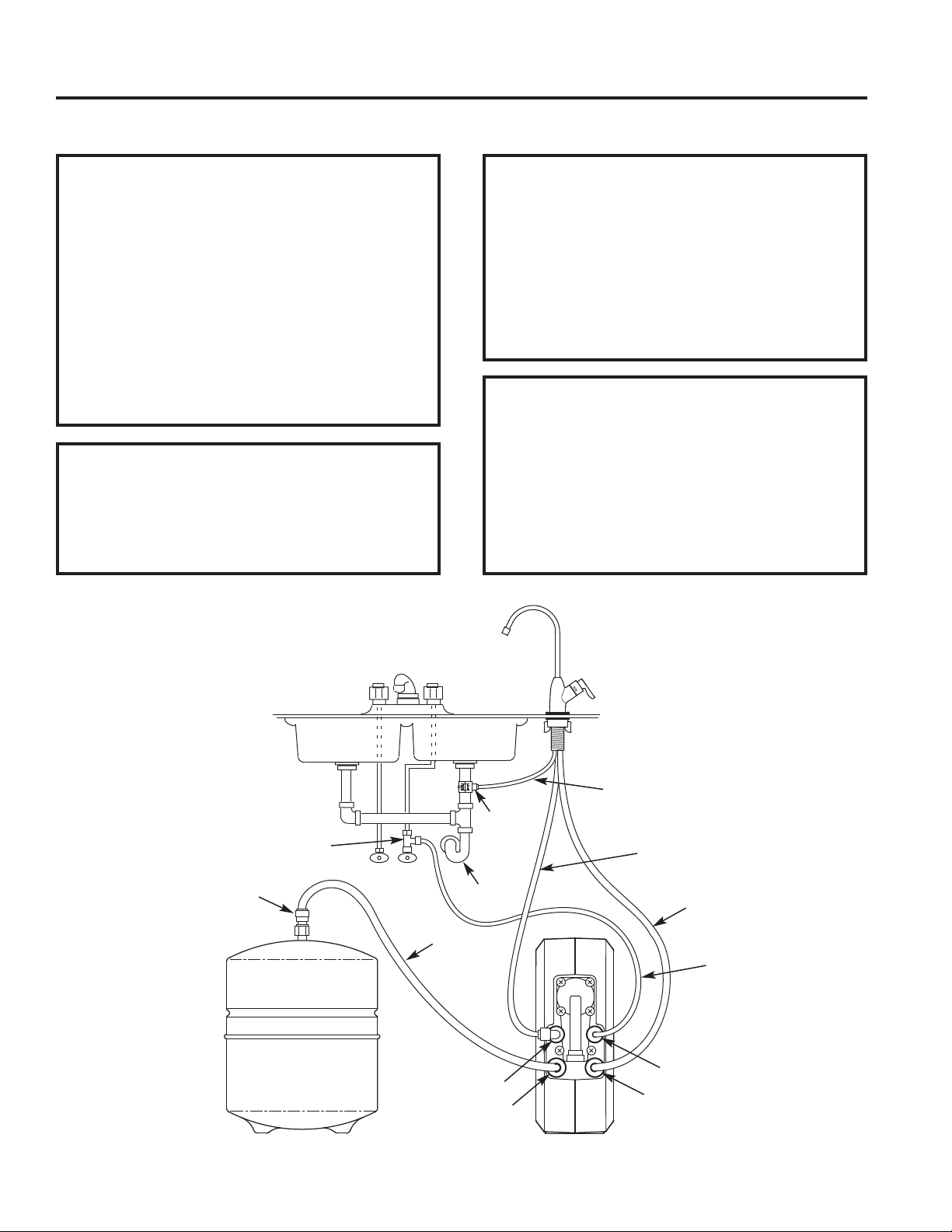
RO Product
Water Faucet
Tank
Connector
3/8” Black
Drain
Water Supply
Fitting
HOT COLD
3/8” Yellow
Tube
Red Collet
Yellow Collet
Storage Tank Reverse Osmosis Assembly
Adapter
Sink
P–Trap
Tube
1/4” Red
Tube
3/8” Blue
Tube
1/4” Green
Tube
Green Collet
Blue Collet
9
Page 10

Installation Instructions
PLAN THE INSTALLATION
The Reverse Osmosis System can be installed under a sink or in a remote location. Typical remote sites are a
laundry room or utility room. Review the location options below and determine where to install the system.
UNDER THE SINK LOCATION
The Reverse Osmosis Filter Assembly and
storage tank may be installed in a kitchen or
bathroom sink cabinet.
REMOTE INTERIOR LOCATION
The Reverse Osmosis Filter Assembly and
storage tank may also be installed in a
remote interior location away from the
Reverse Osmosis faucet. A nearby water
source and drain point are required.
PREPARE FOR INSTALLATION
1. Before starting, close the hot and cold
water shutoff valves.
INSTALATION INSTRUCTIONS
2. Temporarily place tank and filter assembly
into planned location. Check position of
items and space required for installation.
Ensure tubes may be routed without
kinking.
3. Remove tank and filter from planned
location and set aside.
Outside Faucet
(Hard Water)
Soft, Cold Water
Cold Water
Supply
Hard Water Line
Drain Adapter
for Reverse
Osmosis
Reject Water
HOT COLD
Storage
Tank
Sink Drain
Shutoff Valve
P-Trap
Typical Under Sink Installation
Installation items included in parts bag.
Outside Faucet
(Hard Water)
To Faucet
Reverse
Osmosis
Faucet
Reverse
Osmosis
Assembly
10
Soft, Hot Water
Water
Heater
Typical Remote Installation
Additional parts required.
Shutoff
Valve
Water
Softener
Hard
Water
House
Floor
Drain
to
1-1/2”
Air Gap
Water
Meter
Soft water to
Reverse Osmosis
System
Reverse Osmosis
System
Reverse Osmosis
Drain
Storage
Ta nk
Main
Shutoff
Valve
Page 11

Installation Instructions
FEED WATER SUPPLY
Check and comply with local plumbing codes as you plan, then install a cold water supply fitting.
INSTALATION INSTRUCTIONS
A. PREFERRED INSTALLATION
A typical connection using the included water
supply fitting is shown in the illustration below.
1. Close the cold water shutoff valve and open the
faucets to relieve pressure and drain water from
the sink cold water pipe.
cold water
pipe
water supply
fitting
gasket
cold water
shutoff
2. Disconnect the existing cold water line from the
water shutoff valve.
3. Make sure that the water supply fitting’s gasket
is inside the female threaded portion of the
fitting.
4. Install the water supply fitting onto the cold
water shutoff valve, where the existing cold
water line was removed, and hand tighten. Be
careful not to cross thread or overtighten.
5. Connect the existing cold water line to the male
threaded portion of the water supply fitting and
hand tighten. Be careful not to cross thread or
overtighten.
Cold Water
Shutoff Valve
1/4” green
tubing to
Reverse
Osmosis inlet
B. OPTIONAL INSTALLATION
A typical connection using a compression type
fitting (not included).
NOTE: Be sure to turn off the water supply and
open a faucet to drain the pipe.
Complying with plumbing codes, install a fitting on
the cold water pipe to adapt 1/4" OD tubing. A
typical connection is shown in the illustration
below.
Cold Water
Shutoff Valve
1/4” compression
fitting
insert
ferrule
1/4” green
cold water
pipe
NOTE: If threaded fittings are used, be sure to use
pipe joint compound (metal fittings only) or
thread sealing tape on outside threads.
tubing to
Reverse
Osmosis inlet
11
Page 12

Installation Instructions
REVERSE OSMOSIS DRAIN ADAPTER (for under sink installation)
INTRODUCTION
A suitable drain point is needed for the drain water
from the Reverse Osmosis system. Options are:
• Install the included Drain Adapter
As shown below, install the included drain
adapter onto the sink’s drain pipe above the Ptrap. This is normally used for under sink
installations.
Double Basin Sink
Garbage
Disposal
Drain
Adapter
INSTALATION INSTRUCTIONS
NOTE: Do not install drain adapter on a line
coming from a garbage disposal.
• Use another existing drain in the home
Run the drain tube from the RO system directly
to an open drain. This is often used for remote
location installations.
NOTE: An incorrectly connected drain point can
cause water to leak from the faucet’s air gap.
NOTE: Local code may restrict the type of drain
installation to use. Either drain installation
type, if permitted by code, may be used in
under sink or remote location installations.
Consult a plumber if you are not familiar
with plumbing procedures.
P–Trap
Single Basin
P–Trap
Sink
Drain
Adapter
INSTALL DRAIN ADAPTER (Cont.)
RO
Faucet
Drain
Tube
Drain Adapter
P–Trap
2. Using the hole through the drain fitting as a guide,
mark the pipe where a 3/8” hole will be drilled,
and remove the drain adapter from the pipe.
NOTE: Do not drill through the drain adapter’s Q.C.
fitting, as this could damage the o-ring.
Nuts
Drain
Adapter
Halves
Sink Drain Pipe
3/8” Hole - Do not drill
through Q.C. Fitting
3/8” Quick
Connect
Fitting
Screws
P-Trap
12
INSTALL DRAIN ADAPTER
The drain adapter included with the RO system is
designed to fit around a standard 1-1/2” O.D. drain
pipe. In the following procedure, install the drain
adapter above (upstream of) the P-trap. Be sure
to comply with local plumbing codes.
NOTE: Before starting this procedure, inspect the
drain pipe under the sink for corrosion, and replace
if necessary, before continuing with installation.
1. Test fit the two halves of the drain adapter onto
the sink drain pipe, about 6 inches above the Ptrap. Make sure that the quick connect (Q.C.)
fitting is toward the direction of the RO faucet.
NOTE: Locate so that the drain tubing from the
Reverse Osmosis faucet will run straight to
the adapter, with no dips, loops, or kinks.
3. Drill a 3/8” dia. hole in the pipe and remove flash.
4. Clean the sink tailpiece to assure a leak-tight fit.
5. Place the halves of the drain fitting back onto
the sink drain pipe. Use a pencil or similar
pointed object to align the Q.C. fitting so that it
is centered on the hole you drilled.
6. Assemble the nuts and screws, as shown in the
illustration above, and tighten both sides equally
to secure the drain adapter halves onto the pipe.
Do not overtighten.
7. Do not connect black tubing to the Q.C. fitting at
this time. It is done after the RO faucet is installed.
Page 13

Installation Instructions
ALTERNATIVE DRAIN INSTALLATION (for a remote location)
Outside Faucet
Outside Faucet
(Hard Water)
Hard
Water
to
House
Soft, Cold Water
Soft, Hot Water
(Hard Water)
Hard Water Line
Shutoff
Valve
Water
Heater
Water
Softener
Water
Meter
INSTALATION INSTRUCTIONS
BLUE Tubing
to Reverse
Osmosis Faucet
Soft Water GREEN Tubing
to Reverse
Osmosis System
Reverse Osmosis
System
Reverse Osmosis
Drain - RED
Tubing to Drain
YELLOW Tubing
to Storage Tank
Storage Tank
Main Shutoff
Valve
1/4'' RED Tubing
1-1/2”
Air Gap
Air Gap
Laundry
Tub
1-1/2”
Air Gap
Stand pipe
Sump
1-1/2”
Air Gap
INSTALL A DRAIN POINT AND AIR GAP
(for a remote location)
Route the drain tubing to an existing drain in the
house. A floor drain, laundry tub, standpipe, sump,
etc. are suitable drain points. Be sure to provide a
1-1/2” air gap between the end of the hose and the
drain point. This will prevent water from backing
up into the system.
NOTE: Check your local plumbing codes.
To install a remote drain point, complete the
following steps:
1. Locate the 1/4” red tube and determine whether
it is long enough to reach from the Reverse
Osmosis assembly to the drain point.
RED
Tubing to
Drain
1-1/2”
Floor
Drain
2. If longer tubing is required, see parts list in back
of manual and replace the red tube with an
adequate length of 1/4” tubing.
3. Cut one end of the drain tube square.
4. Insert this tube all the way into the red collet
fitting on the Reverse Osmosis filter assembly.
See illustration on page 17.
5. Pull on the tubing to be sure it is held firmly in
the fitting.
NOTE: A flow control insert is located inside the
elbow fitting that the drain tube connects
to. Leave this fitting in place.
6. Route the tubing to the drain point and secure at
the end with a bracket (not included). Provide a
1-1/2” air gap between the end of the tube and
the drain.
13
Page 14

Installation Instructions
STORAGE TANK AND FAUCET
STORAGE TANK INSTALLATION
1. Apply thread sealing tape (2 wraps clockwise) to
the threads on the nipple at the top of the tank.
Ta nk
Nipple
Wrap thread
sealing tape
on threads
Tank Connector
INSTALATION INSTRUCTIONS
2. Locate the included tank connector. Slowly
tighten the tank connector onto the tank nipple
7-8 full turns, so as not to cross thread or
overtighten.
3. Do not connect the tube at this time. This will
occur later in the assembly.
4. Place the storage tank next to the Reverse
Osmosis assembly. The tank can be placed
upright or on its side.
Storage
Ta nk
INSTALL THE FAUCET (Cont.)
1. If drilling is needed, drill a 1-3/8" diameter hole
in the mounting surface. Be sure to use the
proper procedure for drilling stone, porcelain or
stainless steel. Special drill bits may be
needed. Consult a qualified plumber.
RO
Faucet
Base Ring
Gasket
Threaded
Stud
Counter
To p
Washer
Wing
Nut
Tubing
14
INSTALL THE FAUCET
Select the location of the Reverse Osmosis
product water faucet. Be sure there is room
underneath and above the sink to make the
needed connections. Options are:
• Use an existing sink top hole for the spray hose
or soap dispenser (Must be between 1-1/4” and
1-1/2” in diameter)
• Drill a new hole in the sink top
• Drill a new hole in the countertop next to the sink
NOTE: Check to ensure the Reverse Osmosis
faucet will mount flat against the mounting
surface.
NOTE: Visually review the routing of the tubes
from the Reverse Osmosis assembly to the
faucet. Check to ensure there is adequate
tube routing space between the faucet and
Reverse Osmosis assembly.
2. Unscrew the plastic wing nut from the RO
faucet’s threaded stud. Slide this wing nut and
the adjacent metal washer off the tubing ends
and set them aside to reinstall in step 4, below.
NOTE: Be sure the black rubber gasket and metal
base ring remain in place on the faucet
stud.
3. Work tubing and the faucet stud down into the
mounting hole. Be sure that the faucet body
seats squarely into the base ring, and that the
black rubber gasket sits flat against the sink or
countertop.
4. On the underside of the sink or countertop, slide
the metal washer and wing nut (removed in step
2) back over the tubing ends and onto the stud.
With the washer in place between the
countertop and wing nut, tighten the wing nut
securely.
Page 15

Installation Instructions
FAUCET ELECTRONICS
Inside the faucet handle is a battery operated 6 month timer. On a new Reverse Osmosis system, the product water
faucet is shipped with a battery in the holder. After the faucet has been installed, the thin plastic strip must be
removed, as described below, to power up the 6 month timer.
POWER UP THE FAUCET TIMER
1. On the faucet handle, locate the battery cover.
There should be a thin plastic strip that sticks
out from the battery cover.
Faucet
Handle
Plastic Strip pull out and
discard
INSTALATION INSTRUCTIONS
Battery
Cover
2. Grasp the plastic strip, pull it all the way out and
discard it.
3. The LED on the faucet handle will briefly flash
red, then blue, to indicate the 6 month timer is
powered up.
The faucet LED will light blue for a few seconds whenever the faucet handle is operated. When 90% of the filter
lifetime has elapsed, the LED will flash blue 3 times whenever the faucet handle is operated. It will flash red
continuously when 100% (6 months) has elapsed, to indicate that the prefilter and postfilter cartridges must be
changed.
Always change the battery, as shown on page 21, when replacing the prefilter / postfilter cartridges (every 6 months).
15
Page 16
Installation Instructions
HOW TO CONNECT TUBES
The Reverse Osmosis system includes push-in
fittings for quick tubing connection. Review the
following instructions before connecting the tubes
in the next step. Failure to follow these
instructions may lead to future leaks.
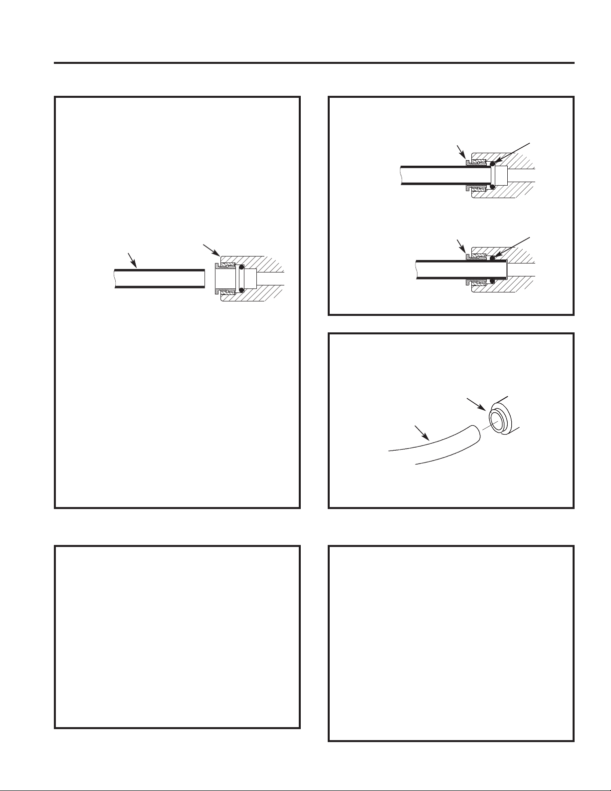
CUT TUBES TO LENGTH
1. Use a sharp cutter or knife to cut the end of
tubing. Always cut the tubing end square and
smooth, with no nicks or rough spots.
Tube
NOTE: Tubing lengths should allow the RO
INSTALATION INSTRUCTIONS
2. Inspect the tube up to 1” from the end to be sure
assembly to be moved for servicing.
there are no nicks, scratches or other rough
spots. If needed, cut the tubing again.
Push-in Fitting
CONNECT TUBES
1. Push tubing through collet, until it engages the
o-ring. Continue pushing until the tube bottoms
out against the back of the fitting. Do not stop
pushing when the tube engages the o-ring.
Failure to follow these instructions may lead to
future leaks. When a 1/4” tube is fully engaged,
11/16” of the tube has entered the fitting. When
a 3/8” tube is fully engaged, 3/4” of the tube has
entered the fitting. Mark tube with a piece of
tape or marker.
2. If additional tubing is required, see parts list at
the end of this manual.
Collet O-Ring
Tube Partially Engaged
Collet O-Ring
Tube Fully Engaged
TO DISCONNECT TUBES (If necessary)
1. Push the collet inward with a finger tip.
Collet (depress to
remove tubing)
Tubing
2. Continue holding collet inward while pulling the
tubing out.
MAKE TUBING CONNECTIONS
YELLOW TUBE
from Reverse Osmosis assembly to
storage tank
1. Locate the 3/8” yellow tube and cut one end
square. See above.
2. Insert all the way into the yellow collet fitting on
the Reverse Osmosis assembly.
3. Route the other end of this tube to the fitting on
top of the storage tank.
4. Cut tube square and to length.
5. Do not connect at this time. This will occur in
the sanitizing step.
16
GREEN TUBE
from cold water supply pipe to
Reverse Osmosis assembly
1. Locate the 1/4” green tube and cut one end
square.
2. Connect to cold water supply fitting. See “Feed
Water Supply” illustrations on page 11.
3. Route the other end of this tube to the green
collet fitting on the Reverse Osmosis assembly.
4. Cut tube square and to length.
5. Insert all the way into the fitting.
6. Pull on the tube to be sure it is held firmly in the
fitting.
Page 17
Installation Instructions
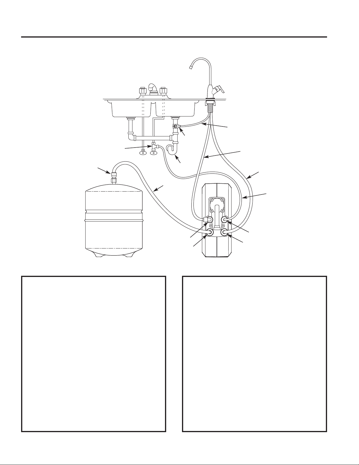
MAKE TUBING CONNECTIONS (Cont.)
Water Supply
Fitting
HOT COLD
Ta nk
Connector
Drain
Adapter
Sink
P–Trap
3/8” Yellow
Tube
INSTALATION INSTRUCTIONS
RO Product
Water Faucet
3/8” Black
Tube
1/4” Red
Tube
3/8” Blue
Tube
1/4” Green
Tube
Storage Tank Reverse Osmosis Assembly
BLUE TUBE
from Reverse Osmosis faucet to
Reverse Osmosis assembly
1. Locate the 3/8” blue tube attached to the faucet.
2. Route the loose end of this tube to the blue
collet fitting on the Reverse Osmosis assembly.
3. Cut tube square and to length.
4. Insert all the way into the fitting.
5. Pull on the tube to be sure it is held firmly in the
fitting.
BLACK TUBE
from Reverse Osmosis faucet to
drain adapter
1. Locate the 3/8" black tube attached to the
faucet.
2. The loose end needs to be attached to the quick
connect fitting on the sink drain adapter.
Red Collet
Yellow Collet
Green Collet
Blue Collet
3. Cut this tube as needed to route it as straight as
possible, without loops, dips, or kinks.
4. Cut the end of the tube square.
5. Insert all the way into the fitting.
6. Pull on the tube to be sure it is held firmly in the
fitting.
RED TUBE
f
rom Reverse Osmosis faucet to
Reverse Osmosis assembly
1. Locate the 1/4” red tube attached to the faucet.
2. Route the loose end of this tube to the red collet
fitting on the Reverse Osmosis assembly.
3. Cut tube square and to length.
4. Insert all the way into the fitting.
5. Pull on the tube to be sure it is held firmly in the
fitting.
17
Page 18

Installation Instructions
SANITIZE THE SYSTEM
SANITIZING THE SYSTEM
Sanitizing is recommended immediately after
installation of the Reverse Osmosis system. It Is
also recommended after servicing inner parts. It is
important that the person installing or servicing the
system have clean hands while handling inner
parts of the system.
Complete the following steps to sanitize the
system.
1. Make sure that the water supply to the Reverse
Osmosis system is off.
2. Open the Reverse Osmosis faucet. If the tank
is not already empty, allow the water to empty.
3. Locate the included eyedropper and common
household bleach (5.25%).
INSTALATION INSTRUCTIONS
Yellow
Tube
Tank
Connector
OPTIONAL SANITIZING KIT
The reusable sanitizing kit (P/N WS35X22001), not
included) is recommended to easily and completely
sanitize the Reverse Osmosis system annually.
Prefilter
Sanitization
Cartridge
RO
Sanitization
Cartridge
Postfilter
Sanitization
Cartridge
The kit includes the following:
• Prefilter sanitization cartridge
(contains no filtration media)
• Postfilter sanitization cartridge
(contains no filtration media)
• RO sanitization cartridge
(contains no RO membrane)
• Syringe, 1 oz.
• Complete instructions
18
4. Add 3 ml. of bleach into open end of yellow
tube. Handle bleach according to bleach
manufacturer’s recommendations.
5. Connect yellow tube to tank connector.
6. Sanitizing the system will be completed during
the pressure test and purging steps on the
following page.
NOTE: The bleach must be removed from the
system before drinking the water. See
purging instructions, following.
Uses standard 5.25% household bleach (not
included) to completely sanitize the Reverse
Osmosis system.
To order, call toll-free GE Appliances Parts and
Services at 877.959.8688.
Page 19

Installation Instructions
TEST AND PURGE THE SYSTEM
INSTALATION INSTRUCTIONS
PRESSURE TEST THE SYSTEM
NOTE: Complete the sanitizing procedure on the
preceding page before pressure testing.
To pressure test the system, complete the
following steps.
1. Open the water supply valve to the Reverse
Osmosis system (see illustration below).
2. Purge air from the house plumbing by opening
several house faucets. Close faucets when
water runs smooth, with no spurting.
3. Pressure will start to build in the RO system. In
about 2 hours check all fittings and connections.
Check for water leaks. Fix leaks if any are
found. If problems exist, refer to the
troubleshooting chart or call the toll free number
below it.
NOTE: When the system is first pressurized, water
may “'spurt”' from the faucet air gap hole
until air is expelled from the RO system.
Reverse
Osmosis
Kitchen
Faucet
Cold Water
Supply
Storage
Tank
Water Supply Shutoff
Valve to Reverse
Osmosis System
Faucet
HOT COLD
PURGE THE SYSTEM
To purge the system, complete the following steps.
1. Open the Reverse Osmosis faucet and let water
flow through the system for a 24 hour period.
Water flow will be a slow trickle at this time.
NOTE: Do not consume water from the RO system
until purging is complete.
2. Close the Reverse Osmosis faucet after the 24
hour purging period is complete.
3. When the purging is finished, your Reverse
Osmosis system is ready for use.
NOTE: As with all other water system applications,
leaks may occur. Because the system
pressure builds slowly, leaks may not be
immediately apparent. Recheck for leaks
24 hours after purging the system is
complete.
OPERATING FEATURES
Please review the following operating
features before using the Reverse
Osmosis system:
• Filtered water will not be available
immediately. It may take several hours to
fill the storage tank and create maximum
flow from the Reverse Osmosis faucet.
• Water Pressure from the Reverse Osmosis
faucet will be less than with a standard
faucet.
• Water will run to the drain while the
Reverse Osmosis system is producing
water, even when water is not being drawn
from the Reverse Osmosis faucet. A small
quantity of water may be heard trickling to
the drain at times when water is not being
drawn from the faucet. This is normal.
Water will automatically stop going to the
drain when the storage tank is full.
19
Page 20

Care and Cleaning
CARTRIDGE LIFE AND REPLACEMENT
PREFILTER / POSTFILTER CARTRIDGE
LIFE
NOTE: It is recommended to replace the battery,
prefilter and postfilter cartridges at least every
6 months of product water use. Replace more
often if they begin to plug with sediment.
The prefilter and postfilter are replaceable sediment
cartridges with activated carbon in their composition.
The prefilter and postfilter cartridges must be
periodically replaced. This will protect the RO
membrane from being destroyed by chlorine. It will
also prevent the filters from plugging with sediment.
Slower output of product water may be noticed as the
prefilter and postfilter build up with sediment. Replace
the prefilter and postfilter cartridges when this occurs.
Replace the faucet battery whenever you replace the
cartridges.
PREFILTER / POSTFILTER CARTRIDGE
REPLACEMENT (every 6 months)
Complete the following steps to replace the prefilter
and postfilter cartridges.
1. Remove (turn counterclockwise) the prefilter
cartridge from the manifold. Then remove the
postfilter cartridge.
2. Discard the cartridges in a proper manner.
3. Install new cartridges in reverse order: postfilter first,
then prefilter. Turn cartridges clockwise to reattach
to the manifold. Do not overtighten.
4. Remove and replace the faucet timer battery. See
next page for instructions.
5. Purge the Reverse Osmosis system. See previous
page for instructions.
REVERSE OSMOSIS MEMBRANE CARTRIDGE
LIFE
The Reverse Osmosis cartridge is a tightly wound
special membrane. The membrane reduces the
dissolved solids and organic matter. The life of the
Reverse Osmosis membrane cartridge depends mostly
on the pH and hardness of the supply water (see
Specifications). Cartridge life is shorter with higher
pH. For example, if supply water pH is from 6.8 to 7.7,
the cartridge may last for well over one year.
However, cartridge life may be as short as 6 months if
the pH is as high as 8.5 to 10. Higher pH weakens the
cartridge membrane and causes pinhole leaks. It Is
time to replace the Reverse Osmosis cartridge when
the production rate and/or quality of product water
drops. Product water may begin to taste different,
indicating solids and organics are passing through the
Reverse Osmosis membrane. See Reverse Osmosis
cartridge replacement.
REVERSE OSMOSIS MEMBRANE CARTRIDGE
REPLACEMENT
Complete the following steps to replace all cartridges
when replacing the RO membrane.
1. Remove (turn counterclockwise) the prefilter
cartridge from the manifold to stop flow to the
Reverse Osmosis cartridge.
2. Remove the Reverse Osmosis cartridge.
3. Remove the postfilter cartridge.
4. Discard the cartridges in a proper manner.
5. Install new cartridges in reverse order: postfilter,
Reverse Osmosis and then prefilter. Turn cartridges
clockwise to reattach to the manifold. Do not
overtighten.
6. Remove and replace the faucet timer battery. See
next page for instructions.
7. Purge the Reverse Osmosis system. See previous
page for instructions.
To obtain replacement filters, call toll-free GE Appliances Parts and Services at 877.959.8688, or
visit the store where you purchased your reverse osmosis system.
Prefilter / Postfilter Cartridge Replacement FQ18PN Carbon Block
CARE AND CLEANING: Cartridge Maintenance and Replacement
Reverse Osmosis Cartridge Replacement FQ18MN Thin Film Polyamide
THE WATER TEST KIT
To obtain an independent laboratory water test kit, please call Legend Technical Services at 1.800.949.8220 and
leave your contact details. They will contact you to find out what water tests you are interested in, and inform you of
the cost of the testing. You will then receive a kit that will include all necessary tests to properly indicate the
performance level of your system. Product water should be tested a minimum of every six months.
NOTE: When the TDS reduction of the system falls below 75%, it is time to replace the reverse osmosis cartridge in
addition to the prefilter and postfilter.
20
Page 21
Care and Cleaning
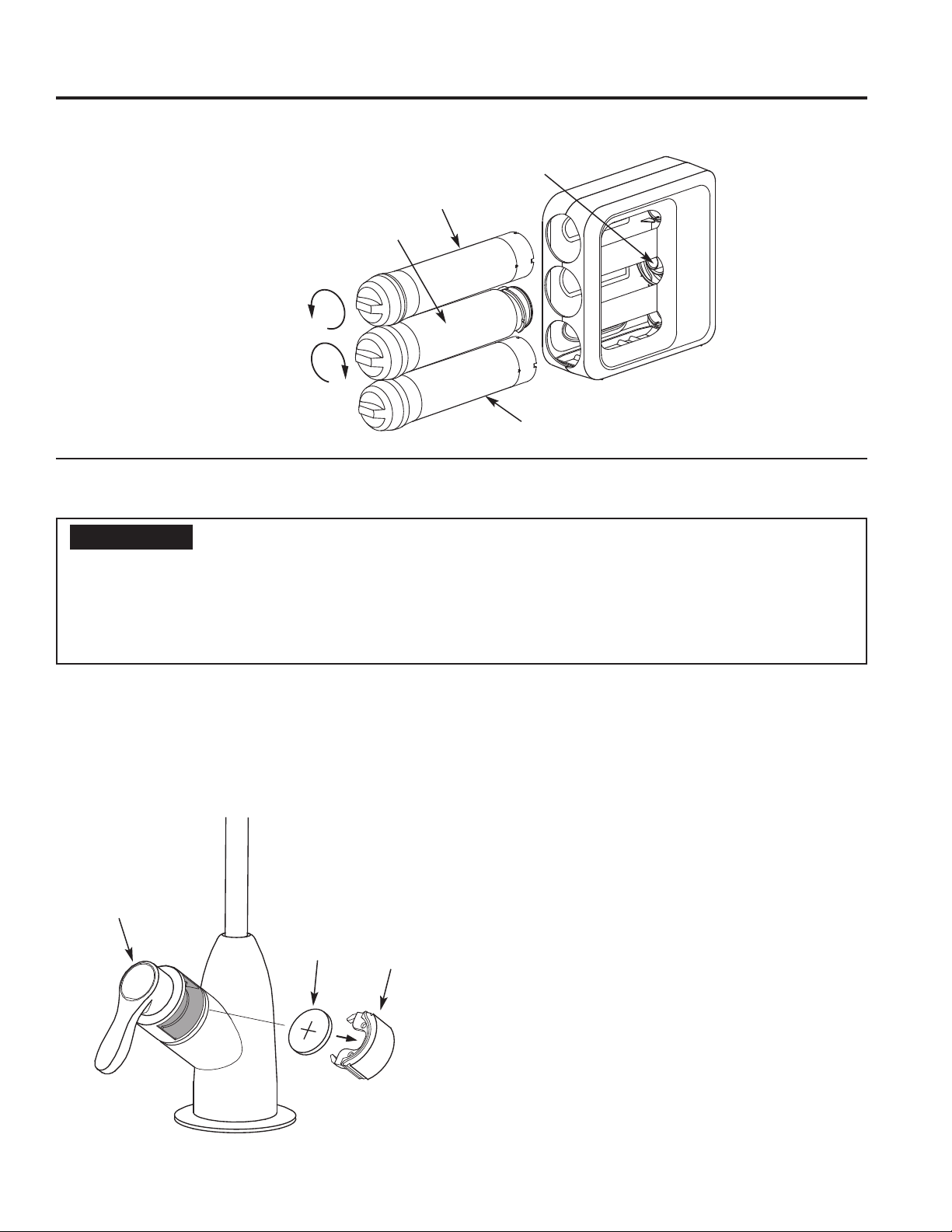
CARTRIDGE REPLACEMENT (Cont.)
CARE AND CLEANING: Cartridge Replacement and Faucet Battery
Prefilter
Cartridge
RO
Cartridge
Turn filter cartridges
counterclockwise
to remove from manifold
Turn filter cartridges
clockwise
to attach to manifold
Manifold
Postfilter
Cartridge
CHANGE FAUCET BATTERY
WARNING
■ Keep batteries away from children. This product contains a lithium button cell battery. If a new or used lithium
button cell battery is swallowed or enters the body, it can cause severe internal burns and can lead to death in
as little as 2 hours. If you think batteries might have been swallowed or placed inside any part of the body, seek
immediate medical attention. Always completely secure the battery compartment. If the battery compartment
does not close securely, stop using the product, remove the battery and keep it away from children. Properly
dispose of used batteries, keeping them away from children.
Chemical Burn Hazard:
A new battery is included with the replacement prefilter
/ postfilter cartridge kit. Always change the battery, as
shown below, when replacing the prefilter/ postfilter
cartridges (every 6 months).
1. Locate the battery holder cover on the RO product
water faucet’s handle.
Faucet
Handle
Battery
(CR 2032)
Battery
Holder
Cover
2. Grip the cover by the gaps at each side, and firmly
pull it all the way out of the faucet. A screwdriver
may be used to pry up the cover, but be careful not
to scratch or nick the finish.
3. Pull the old battery out of the holder and replace it
with the new battery from the replacement prefilter /
postfilter cartridge kit (Lithium CR 2032 button battery
or equivalent). Place battery into the holder with the
positive (+) side facing up, or away from the faucet’s
base.
4. Slide the battery holder back into the opening in the
faucet’s handle, making sure it is oriented correctly
(it will not fit if upside-down). Push it all the way in
until the cover is flush.
5. When the battery is installed, the faucet LED will
briefly flash red then blue. The timer begins its 6
month countdown. Whenever the faucet handle is
operated, the blue LED will light for a few seconds.
The LED will not light if the battery was placed into
the holder upside-down.
21
Page 22
Care and Cleaning
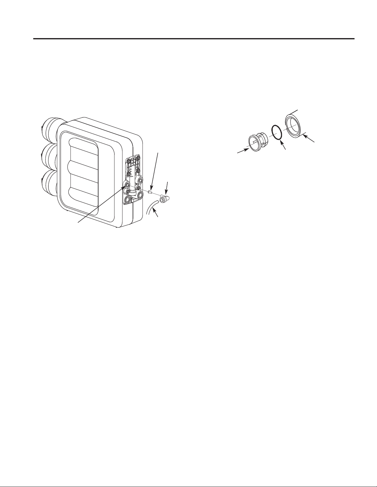
DRAIN FLOW CONTROL
The flow control is required for proper operation of the
Reverse Osmosis system. See illustration below. The
flow control, located inside the push-in elbow fitting on
the drain port of the Reverse Osmosis assembly,
keeps water flowing through the membrane at the
required rate. This ensures that the system produces
the best quality product water.
Flow Control
Insert
Push-in
Elbow
Fitting
Drain Port
1/4” Red
Tubing to Drain
ASSEMBLING COLLET AND O-RING
1. Remove the collet and o-ring from the fitting with a
small screwdriver. Do not scratch the internal walls
of the fitting port.
2. Clean collet port, lubricate with silicone-based
lubricant, and insert the o-ring seal into the bottom
of the port.
Fitting Port
Collet
3. Push the collet inward until it locks in place.
O-Ring Seal
Periodically check the flow control to be sure the small
hole through it is clean and unrestricted.
If the flow control requires service, review the
CARE AND CLEANING: Drain Flow Control
exploded view above. Assemble and disassemble as
shown. If the flow control remains in the manifold
when the push-in elbow fitting is removed, it will be
necessary to remove the drain port’s collet and o-ring,
as shown in the next section, to retrieve it.
22
Page 23

Troubleshooting Tips... Before you call for service
Save time and money! Review the following chart first and you may not need to call for service.
Problem Possible Causes What To Do
Water has air bubbles
and is cloudy
Indicator light on
faucet handle not
working
Chlorine taste and/or
odor in the Reverse
Osmosis product
water
Other taste and/or
odor
Water leaking from
faucet air gap hole
System makes
product water slowly
No water
Leaks at fittings
Sounds you may hear
Air in system after installation. Will go away after it runs for a while.
Battery installed incorrectly. Observe orientation on page 21 and install correctly.
Battery is dead. Replace with new Lithium CR 2032, 3-volt battery.
The ppm of chlorine in your water
supply exceeds maximum limits
and has destroyed the Reverse
Osmosis membrane.
The prefilter is no longer reducing
chlorine from the water supply.
High quality product water may
have a different taste than what
you’re used to.
Low water usage. Completely drain system and allow to refill.
Contamination in product water
storage.
Prefilter and postfilter need to be
changed.
Drain side of faucet air gap (3/8”
tubing) plugged, restricted or
incorrectly connected to the
drain.
This is normal. Water flow rate will be lower than a regular faucet. It takes
Water supply to the Reverse
Osmosis system not within
specifications.
Prefilter cartridge plugged with
sediments.
Reverse Osmosis membrane
plugged with sediments.
Water supply valve not turned on. Turn water supply valve on. See illustration on page 19.
After filter change, tank is empty. It takes several hours for RO system to provide enough water
Improperly installed. Reinstall. See Installation Instructions.
Sink drain, drain water from
system.
Faucet air gap drain water flowing
through the faucet air gap. This
may be associated with high
pressure water supply, generally
80 psi or greater.
If the water supply contains more than 2.0 ppm of chlorine,
additional filtering of the water supply to the Reverse Osmosis
is needed. Correct this condition before doing maintenance on
the Reverse Osmosis system.
Replace the Reverse Osmosis membrane cartridge, prefilter,
postfilter and battery in the faucet handle.
This is normal.
Use sanitizing procedure.
Replace the prefilter and postfilter. Sanitize system.
Inspect and eliminate restriction or plug. It is important that
there are no dips, loops or low spots in the drain line from the
faucet air gap to the drain pipe. Refer to Installation Instructions
for proper drain connection. If drain line adapter was used as
the drain point, periodic inspection/cleaning is recommended.
several hours to fill the tank.
Increase water pressure, precondition the water, etc., as
needed to conform before doing maintenance on the Reverse
Osmosis system.
Replace the prefilter. If rate does not increase, replace the
postfilter, Reverse Osmosis membrane cartridge and battery in
the faucet handle.
Replace Reverse Osmosis membrane cartridge and battery in
the faucet handle.
to fill the tank.
This is normal.
Drain line can be installed to an alternate drain, such as a
basement drain. See page 13 for alternate drain
configurations.
Install a pressure regulator in the house water supply system to
reduce the pressure below 80 psi.
TROUBLESHOOTING TIPS
If you are still having trouble, please visit www.GEAppliances.com/ge/service-and-support/contact.htm or
call us at 800.626.2005.
23
Page 24

Parts List
PARTS LIST
2
3
GXRQ18NBN and GNRQ18NBN
1
4
5
11
12
8
9
10
6
7
13
15
14
24
Page 25

Parts Catalog
PARTS CATALOG
QUANTITY
G
X
R
Q
1
GE
REF.
NO.
0001 WS19X21938 CABINET ASSEMBLY, LEFT HALF, RIGHT HALF,
0002 FQ18PN PRE AND POST FILTER CARTRIDGE SET,
0003 FQ18MN RO CARTRIDGE 1 1
0004 WS19X21937 MANIFOLD ASSEMBLY
0005 WS03X21933 DIAPHRAGM KIT 1 1
0006 WS15X21935 CHECK VALVE KIT 1 1
0007 WS15X21932 AUTOMATIC SHUTOFF KIT 1 1
0008 WS15X21988 COLLET KIT, 1/4” (SET OF 2) 1 1
0009 WS15X21989 COLLET KIT, 3/8” (SET OF 2) 1 1
0010 WS02X21934 FLOW CONTROL KIT 1 1
0011 WS32X10012 STORAGE TANK 1 1
0012 WS22X21939 TANK CONNECTOR 1 1
0013 WS15X21941 FAUCET 1 1
0014 WS18X21940 DRAIN ADAPTER 1 1
0015 WS18X21936 WATER SUPPLY FITTING 1 1
0016 WS35X22001 SANITIZATION KIT (OPTIONAL - SEE SANITIZING
0017 WS35X22002 AUXILIARY STORAGE TANK (OPTIONAL -
0018 WS07X10006 TUBING, 1/4” O.D. X 20 FEET LONG, WHITE
0019 WS07X10008 TUBING, 3/8” O.D. X 20 FEET LONG, WHITE
0020 WS01X22003 DROPPER 1 1
0999 Manual Online OWNER’S MANUAL & INSTALLATION
APPLIANCES
PART NO. PART DESCRIPTION
AND DRIP TRAY
INCLUDING BATTERY (NOT SHOWN)
(INCLUDES REF. NO. 0001 AND 0005 THRU 0009)
INSTRUCTIONS FOR ILLUSTRATION)
INCLUDES REF. NO. 0011 AND FITTINGS TO
PLUMB IN PARALLEL WITH ORIGINAL TANK)
(OPTIONAL FOR REMOTE INSTALLATION)
(OPTIONAL FOR REMOTE INSTALLATION)
INSTRUCTIONS
8
N
B
N
1 1
1 1
1 1
1 1
1 1
1 1
1 1
1 1
G
N
R
Q
1
8
N
B
N
25
Page 26

GE Appliances Reverse Osmosis System Warranty
GEAppliances.com
All warranty service provided by our SmartWater™ Authorized Servicer Network. To schedule service, contact us
toll free at 800.GE.CARES. Please have serial number and model number available when calling for service.
For the period of GE Appliances will replace
WARRANTY
One year
from the date of the original purchase
What GE Appliances will not cover
■ Service trips to your home to teach you how to use
the product.
■ Improper installation, delivery, or maintenance.
■ Failure of the product if it is abused, misused,
modified, or used for other than the intended
purpose or used commercially.
■ Use of this product where water is microbiologically
unsafe or of unknown quality, without adequate
disinfection. Systems certified for cyst reduction
may be used on disinfected water that may contain
filterable cysts.
Any part of the Reverse Osmosis Filtration System which fails due to a
defect in materials or workmanship.
■ Filter cartridges, membrane cartridges and batteries
after 30 days from date of purchase.
■ Damage to the product caused by accident, fire,
floods or acts of God.
■ Incidental or consequential damage caused by
possible defects with this appliance.
EXCLUSION OF IMPLIED WARRANTIES
Your sole and exclusive remedy is product repair as provided in this Limited Warranty. Any implied warranties,
including the implied warranties of merchantability or fitness for a particular purpose, are limited to one year or
the shortest period allowed by law.
This warranty is extended to the original purchaser and any succeeding owner for products purchased for home use
within the USA. If the product is located in an area where service by a GE Appliances Authorized Servicer is not
available, you may be responsible for a trip charge or you may be required to bring the product to an Authorized GE
Appliances Service location for service. In Alaska, the warranty excludes the cost of shipping or service calls to your
home.
Some states do not allow the exclusion or limitation of incidental or consequential damages. This warranty gives
you specific legal rights, and you may also have other rights which vary from state to state. To know what your legal
rights are, consult your local or state consumer affairs office or your state’s Attorney General.
Warrantor: GE Appliances
date is needed to obtain service under the warranty.
Staple your receipt here. Proof of the original purchase
26
Page 27

Notes
NOTES
27
Page 28

Consumer Support
GE Appliances Website
Have a question or need assistance with your appliance? Try the GE Appliances Website 24 hours a day, any day
of the year! You can also shop for more great GE Appliances products and take advantage of all our on-line support
services designed for your convenience. In the US: GEAppliances.com
Register Your Appliance
Register your new appliance online at your convenience! Timely product registration will allow for enhanced
communication and prompt service under the terms of your warranty, should the need arise. You may also mail in
the pre-printed registration card included in the packing material. In the US: GEAppliances.com/register
Schedule Service
Expert GE Appliances repair service is only one step away from your door. Go online and schedule your service at
your convenience any day of the year. In the US: GEAppliances.com/ge/service-and-support/service.htm or
call 800.432.2737 during normal business hours.
CONSUMER SUPPORT
Extended Warranties
Purchase a GE Appliances extended warranty and learn about special discounts that are available while your
warranty is still in effect. You can purchase it online anytime. GE Appliances Services will still be there after your
warranty expires. In the US: GEAppliances.com/ge/service-and-support/shop-for-extended-service-plans.htm
or call 800.626.2224 during normal business hours.
Parts and Accessories
Individuals qualified to service their own appliances can have parts or accessories sent directly to their homes
(VISA, MasterCard and Discover cards are accepted). Order online today 24 hours every day. In the US:
GEAppliances.com or call 877.959.8688 during normal business hours.
Instructions contained in this manual cover procedures to be performed by any user. Other servicing
generally should be referred to qualified service personnel. Caution must be exercised, since improper
servicing may cause unsafe operation.
Contact Us
If you are not satisfied with the service you receive from GE Appliances, contact us on our Website with all the
details including your phone number, or write to:
In the US: General Manager, Customer Relations | GE Appliances, Appliance Park | Louisville, KY 40225
GEAppliances.com/ge/service-and-support/contact.htm
28
Printed in the United States
 Loading...