

Page 1
GN94DNSRSA
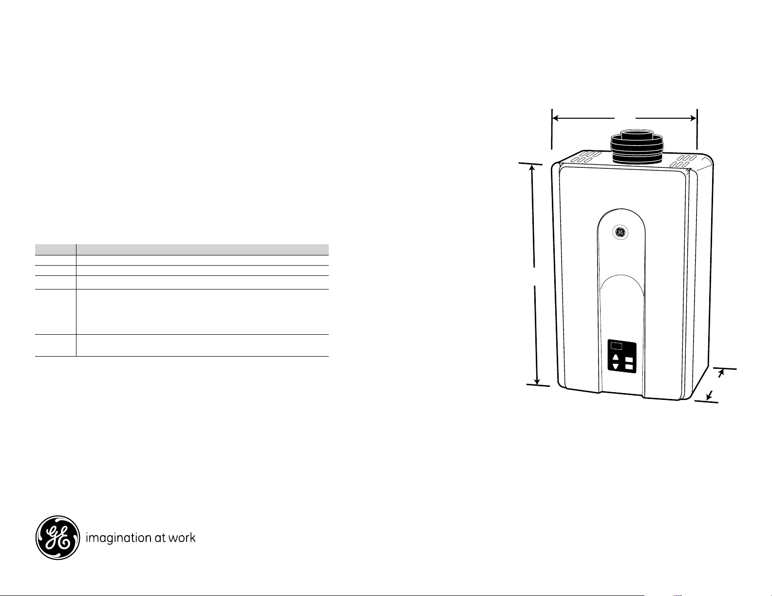
22-7/8
9-5/8
14
GE® Indoor Tankless Water Heater
Dimensions and Installation Information (in inches)
Important: All units must be installed according
to local codes.
Note: Before installing, consult installation
instructions packed with product for current
dimensional data.
Parts Warranty: Limited 5 year; Limited 10 year
Heat Exchanger
Labor Warranty: Limited 1 year Entire Appliance
Warranty Notes: Limited 1 year
Tankless gas water heater accessories
Model # Description
AGTRC1 Direct-wire remote controller for point-of-use locations
AGTPCM Pipe cover hides connections for seamless appearance
AGTDC1 Dual-connect cable to cascade 2 tankless units together
AGTCK1 Multi-connect kit with control board allows 3, 4 or 5 units to
connect and operate as one unit using the add-on control board
as a system hub. Requires 1 multi-connect cable (AGTMC1) for
each unit added.
AGTMC1 Multi-connect cable to be used with AGTCK1 to connect 3, 4 or 5
units. One multi-connect kit required for each unit added.
For answers to your Monogram,® GE Profile™ or
GE® appliance questions, visit our website at
ge.com or call GE Answer Center® service,
800.626.2000.
Specification Created 1/08
380301
Page 2
GN94DNSRSA
FIXED CLOSED
OPERABLE
B
I
M
G
H
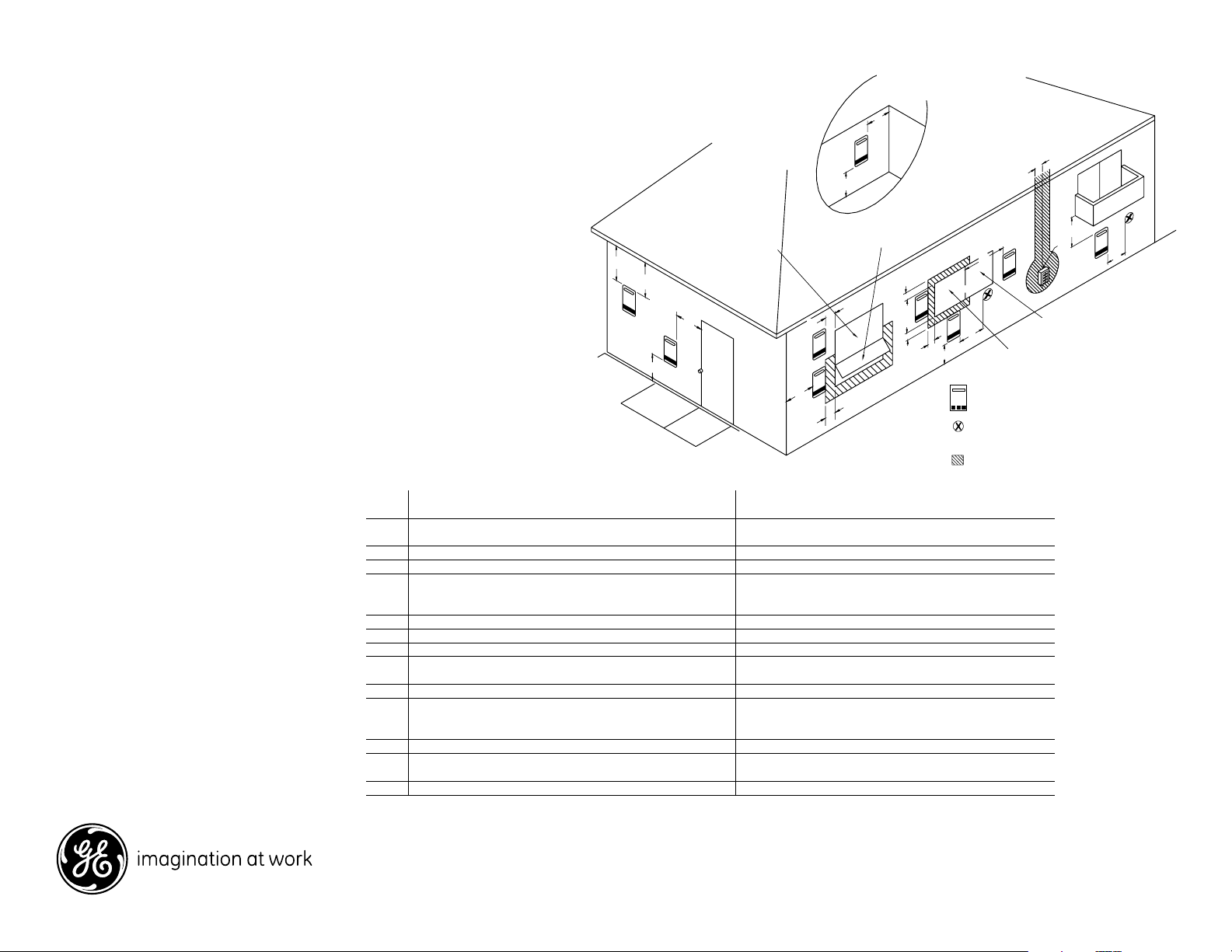
VENT TERMINAL
AIR SUPPLY INLET
AREA WHERE TERMINAL
IS NOT PERMITTED
INSIDE
CORNER DETAIL
K
B
B
B
A
J
FIXED CLOSED
OPERABLE
C
F
B
B
L
D
E
A
GE® Indoor Tankless Water Heater
Dimensions and Installation Information (in inches)
Locating the Unit
•
Install the unit in a location central to where hot water is used.
• Sizing guide is based on the following:
• In homes with large hot water demand consider locating the
tankless hot water heaters in different parts of the home near
the point of use for optimal performance (you may cascade
up to 5 total units).
• If installing indoors, consider installing on an exterior wall to
minimize vent length.
• The compact design allows several location options: closet,
garage, basement laundry/mud room; even under stairs.
Flue Terminal Clearance Chart
Ref
Clearance above grade, veranda, porch, deck
A
or snowline
B Clearance to window or door that may be opened 12 inches (30 cm)
C Clearance to permanently closed window *
Vertical clearance to ventilated soffit, located above the terminal
D
within a horizontal distance of 2 feet
(61 cm) from the center line of the terminal
E Clearance to unventilated soffit *
F Clearance to outside corner *
G Clearance to inside corner *
Clearance to each side of center line extended above meter/
H
regulator assembly
I Clearance to service regulator vent outlet *
Clearance to non-mechanical air supply inlet
J
to building or the combustion air inlet to any
other appliance
K Clearance to a mechanical air supply 3 feet (91 cm) above if within 10 feet (3 m) horizontally
Clearance above paved sidewalk or paved driveway located on
L
public property 1
M
Clearance under veranda, porch, deck or balcony 2
* For clearances not specified in ANZI Z223.1/NFPA 54, clearances are in accordance with local installation codes and the requirements of
the gas supplier. Clearance to opposite wall is 24 inches (60 cm).
1 A Vent shall not terminate directly above a sidewalk or paved driveway that is located between two single family dwellings and serves
both dwellings.
2 Permitted only if veranda, porch, deck or balcony is fully open on a minimum of two sides beneath the floor.
For answers to your Monogram,® GE Profile™ or
GE® appliance questions, visit our website at
ge.com or call GE Answer Center® service,
800.626.2000.
Description
U.S. Installation Clearances
Per ANSI Z21.10.3
36 inches (91 cm)
*
*
12 inches (30 cm)
*
*
Specification Created 1/08
380301
Page 3

GN94DNSRSA
Pipe cover not required. However,
consideration should be taken in the
design of the rough plumbing to allow
installation of unit and pipe cover.
Optional Pipe Cover (AGTPCM)
shown shaded.
* Suggested area for Water and Gas lines to
come through the wall to allow the optional
pipe cover to be installed if desired.
Water and Gas
from below
9
7
⁄
8
”
2
1
⁄
2
”
2
1
⁄
2
”
2
1
⁄
2
”
4
1
⁄
2
”
7”
12”
3
3
⁄
8
”
6”
12”
9”
Floor
Unit
18” min.
18” min.
6
1
⁄
2
”
9
7
⁄
8
”
2
1
⁄
2
”
2
1
⁄
2
”
2
1
⁄
2
”
4
1
⁄
2
”
7”
12”
3
3
⁄
8
”
6”
12”
9”
Floor
Unit
GE® Indoor Tankless Water Heater
Dimensions and Installation Information (in inches)
Installation:
Planning for plumbing
(shown with optional pipe cover)
The center of the pipes can be
placed anywhere within the
shaded area.
The center of the pipes is
recommended to be protruding
only within 6" of the mounting
wall. Other specific installations
may be different.
Be sure that the minimum
elevation of the bottom of
the unit is 18" to meet the 36"
recommended clearance for the
exhaust.
Note: It is recommended to install
the bottom of the unit at least
18" off the ground to minimize
blockage from debris and provide
room for the optional Pipe Cover
Accessory, AGTPCM.
For answers to your Monogram,® GE Profile™ or
GE® appliance questions, visit our website at
ge.com or call GE Answer Center® service,
800.626.2000.
Clearances for tankless gas water heater (inch/mm)
To
combustibles
non combustibles
To
For servicing
and operation
Top of heater 12 (305) 2 (51) 2 (51)
Back of heater 0 (0) 0 (0) 0 (0)
Front of heater 24 (610) 24 (610) 24 (610)
Sides of heater 6 (152) 1/2 (13) 1/2 (13)
Floor/Ground 12 (305) 2 (51) 2 (51)
Specification Created 1/08
380301
Page 4

GN94DNSRSA
GE® Indoor Tankless Water Heater
Dimensions and Installation Information (in inches)
Additional clearances—vent terminal
These clearances are applicable to both
concentric termination and non-concentric vent
exhaust terminations.
• Avoid termination locations near a dryer vent.
• Avoid termination locations near
commercial cooking exhaust
Vent Length Calculations
Maximum System performance is achieved at a vent length of 21
equivalent feet or less. The system is capable of 41 equivalent feet length if
required, but this reduces system performance. For vent length calculations,
a 90˚ elbow counts as 6 feet and a 45˚ elbow counts as 3 feet—see the
chart below.
Concentric Vent Piece Equivalent Length
Straight 1 ft (per foot length)
90˚ elbow 6 ft each
45˚ elbow 3 ft each
Total vent length = straight ft + 90˚ elbows x 6 ft + 45˚ elbow x 3ft
Note: Vent dimensions = up to 5 3/4 inches. Please read vent supplier's
installation manual for specific dimensions.
FLUE INSTALLATION - CONDENSATE DRAIN
HORIZONTAL TERMINATION WITH A CONDENSATE DRAIN
For answers to your Monogram,® GE Profile™ or
GE® appliance questions, visit our website at
ge.com or call GE Answer Center® service,
800.626.2000.
VERTICAL TERMINATION (condensate collector
required in all installations)
Specification Created 1/08
380301
Page 5

GN94DNSRSA
GE® Indoor Tankless Water Heater
Features and Benefits
• Continuous Hot Water*
• Energy Savings - Save up to 25% annually on your water heating bill**
• Compact Design - Frees up floor space with wall-mounted installation
• Installation Flexibility - Can be wall-mounted in many areas of the home
• Helps to Avoid Carbon Emissions - Up to 25% tied to your water heating
compared to a standard 40-gallon gas tank model based on Department
of Energy testing
• Demand-Activated Technology - Only heats the water when needed
• Precise Temp - Within +/- 3˚ F
• Freeze Protect - Protects your water heater from freezing at temperatures that
can drop as low as -30° F
SM
• A Product of Ecomagination
• Model GN94DNSRSA - Silver metallic
* Flow rates may diminish based on simultaneous use of multiple showers/baths
and/or appliances
** Compared to a standard 40-gallon gas tank model based on 2007 fuel costs
per DOE testing
Specification Created 1/08
380301
 Loading...