

Page 1
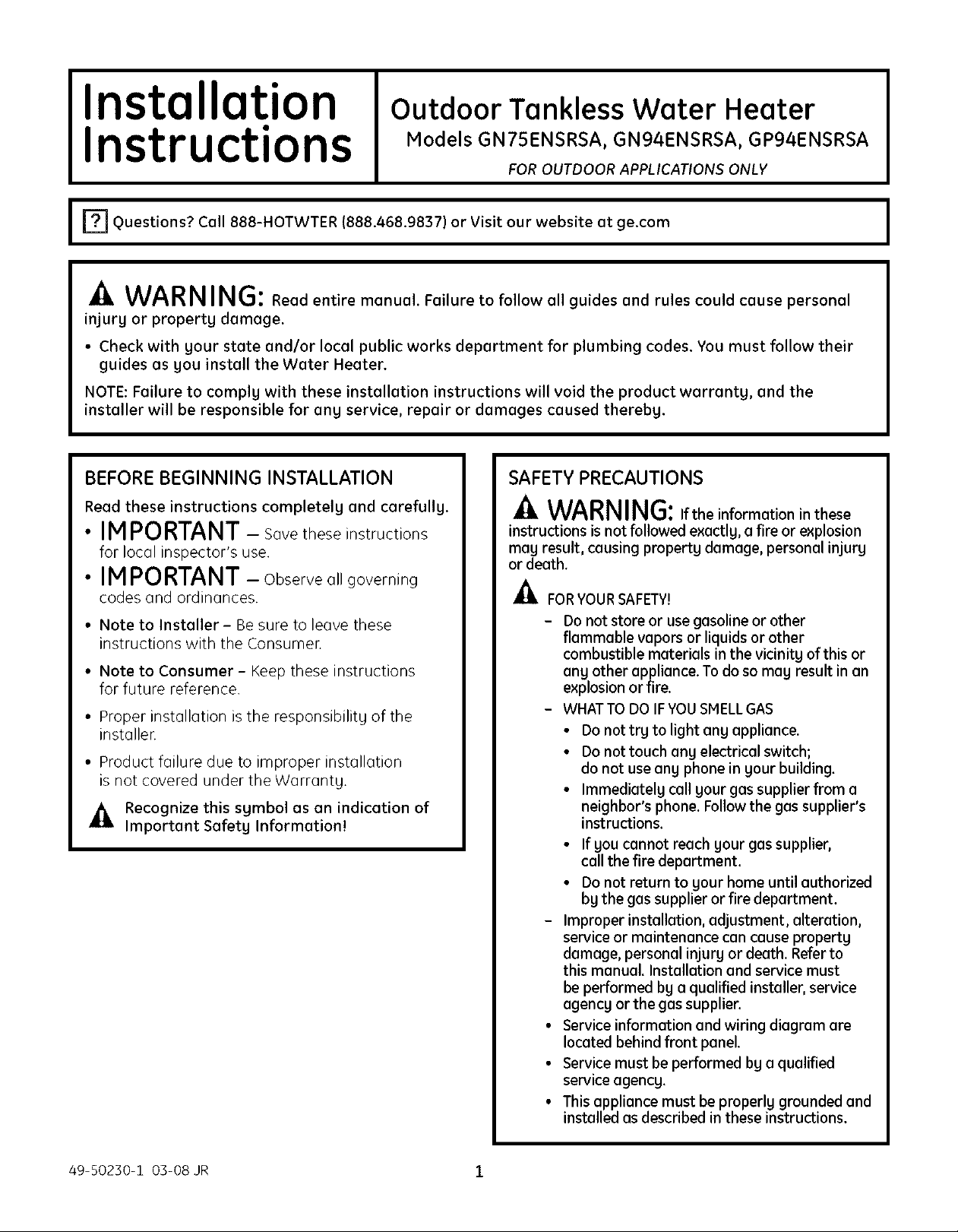
Installation
Outdoor Tankless Water Heater
Instructions
I F?I Questions? Call 888-HOTWTER (888.468.9837) or Visit our website at ge.com I
Models GN75ENSRSA, GN94ENSRSA, GP94ENSRSA
FOR OUTDOOR APPLICATIONS ONLY
WARNING: Read entire manual. Failure to follow all guides and rules could cause personal
injury or property damage.
• Check with your stote and/or local public works department for plumbing codes. You must follow their
guides as gou install the Water Heater.
NOTE: Failure to complg with these installation instructions will void the product warranty, and the
installer will be responsible for ang service, repair or damages caused therebg.
BEFORE BEGINNING INSTALLATION
Read these instructions completely and carefully.
• IMPORTANT - Sovetheseinstructions
for Iocol inspector's use.
•INPORTANT - Observeoligoverning
codes ond ordinonces.
• Note to Installer - Be sure to leove these
instructions with the Consumer.
• Note to Consumer - Keep these instructions
for future reference.
• Proper instollotion is the responsibilitg of the
instoller.
• Product foilure due to improper instollotion
is not covered under the Worrontg.
_, Recognize this symbol as an indication of
Important Safety Information!
SAFETY PRECAUTIONS
-4,WARNING:,ftheinformationinthese
instructions is not followed exactlg, a fire or explosion
may result, causing property damage, personal injury
or death.
_FOR YOUR SAFETY!
- Do notstore or use gasoline or other
flammable vapors or liquids or other
combustible materials in the vicinitg of this or
ang other appliance. To do so may result in an
explosion or fire,
- WHAT TO DO IFYOUSMELLGAS
• Do not trg to light ang appliance.
• Do not touch ang electrical switch;
do not use ang phone in gour building.
• Immediatelg call gour gas supplier from a
neighbor's phone. Follow the gas supplier's
instructions.
• Ifgou cannot reach gour gas supplier,
call the fire department.
• Do not return to gour home until authorized
bg the gas supplier or fire department.
- Improper installation, adjustment, alteration,
service or maintenance can cause propertg
damage, personal injurg or death. Refer to
this manual. Installation and service must
be performed bg a qualified installer, service
agencg or the gas supplier.
• Service information and wiring diagram are
located behind front panel.
• Service must be performed bg a qualified
service agencg.
• This appliance must be properlg grounded and
installed as described in these instructions.
49-50230-1 03-08 JR 1
Page 2
Installation Instructions
SAFETY PRECAUTIONS (cont.)
• Theappliance must be isolated from the gas
supply piping system by closing its individual
manual shut-off valve during any pressure
testing of the gas supply piping system at test
pressures equal to or less than 1/2 psi (B.5kPa)
(13.84 in W.C.).
SAFETY PRECAUTIONS (cont.)
WARNING: Gasoline, as well
as other flammable materials and liquids
(adhesives, solvents, paint thinners, etc.) and
the vapors theg produce, are extremelg
dangerous. DO NOT handle, use or store gasoline
or other flammable or combustible materials
angwhere near or in the vicinitg of a water
heater or ang other appliance. Be sure to reed
and follow the labels on the water heater, as well
as the warnings printed in this manual. Failure
to do so can result in propertg damage, bodilg
injurg or death.
WARNING: Donotuse substitute
materials. Use onlg parts certified with the
appliance.
• This appliance must be installed, inspected and
leak tested by a state- and city-qualified licensed
contractor. It is the responsibility of the person
having the water heater installed to ensure the
installing contractor has proper licenses and
permits for installing water heaters in your
location. GE highly recommends that installers
attend a product knowledge class to ensure
customer satisfaction and warranty coverage.
Failure to comply with state and local codes
pertaining to water heater installations may
void the warranty.
• This appliance is not to be installed indoors.
• The installation must conform with local codes or,
in the absence of local codes, with the Notional
Fuel Gas Code, ANSI Z223.1/NFPA 54, or the
Natural Gas and Propane Installation Code,
CSA B149.1.
• Theappliance and its appliance main gas valve
must be disconnected from the gas supply piping
system during any pressure testing of that
system at test pressures in excess of 1/2 psi
(3.5kPa)(13.8/4in W.C.).
• The appliance should be located in an area
where water leakage of the unit or connections
will not result in damage to the area adjacent
to the appliance or lower floors of the structure.
When such locations cannot be avoided,
it is recommended that a suitable drain pan,
adequately drained, be installed under the
appliance. The pan must not restrict combustion
airflow.
• The flow of combustion and ventilation air shall
not be obstructed.
• This appliance is not suitable for use in an
application such as a pool or spa heater that
uses chemically treated waten (This appliance is
suitable for filling large or whirlpool bath tubs
with potable water.)
• If a water heater is installed in a closed-water
supply system, such as one having a backflow
preventer in the cold water supply line, means
shall be provided to control thermal expansion.
Contact the water supplier or local plumbing
inspector on how to control this situation.
• Should overheating occur or the gas supply fail
to shut off, turn off the manual gas control valve
to the appliance.
• Keep the air intake location free of chemicals,
such as chlorine or bleach, that produce fumes.
These fumes can damage components and
reduce the life of your appliance.
CAUTION:DONOToperate thewater
heater if any part of the appliance has been under
waten
CAUTION: BURN HAZARD. Hot exhaust
and vent may cause seriousburns.Keep back from
water heaterunit.Keep smallchildrenand animals
away from unit.
CAUTION:Hot Water outlet pipes leaving
unit can be hot to touch. Insulation must be used
for hot water pipes below S6"due to burn risk to
children.
WARNING: This unit is not intended
or qualified for use in manufactured homes, mobile
homes or recreational vehicles.
2
Page 3
Installation Instructions
PARTS PROVIDED
Locate the parts packed with the Water Heater.
GasValve
3/4" FNPTBailValve
/_ "("o"_'/
C,,°,o:9
WoodScrews
Remote
Control
TOOLS YOU WILL NEED
• Pipe Wrenches (2)
• Adjustable Pliers
• Screwdrivers (2)
• Wire Cutters
• Gloves
• Safety Glasses
MATERIALS YOU WILL NEED TO SUPPLY
• Soap Solution
• Pipe Compound
• 5/8" ID PVC Flexible
Tubing
• 2 Conductor 22 AWG
Wire for Remote
Control
• Single Gang Electrical Box
• Wire Nuts
• Outdoor Rated Switch and Enclosure
• Concrete Wall Anchors (Optional)
• 3/4" Pipe Fittings
Required:
- Unions
- Ball Valves
- Drain Valves
- Pressure Relief Valve
OTHER TOOLS THAT MIGHT BE REQUIRED
• Hammer Drill with Concrete Bits
• Saw
• Threading Hachine with Heads and Oiler
• Core Drill with Diamond Head
• Torch Set
• Copper Tubing Cutter
• Steel Pipe Cutter
OTHERMATERIALSTHATMIGHT BENEEDED
• Heat Tape
• Pipe Insulation
• Electrical Wire and Conduit per Local Code
• Air Inlet Screen
• Optional Pipe Cover AGTPCH
• Optional Additional Remote Controller AGTRC1
Your instellation components moy vory.
3
Page 4

DIMENSIONS
f°_o _ o_/
Installation Instructions
GN75IGNg41GPg4ENSRSA
DIM. DESCRIPTION IN. (MM)
A Width 14 (355.6)
B Depth 9n/:s (249.5)
C Height - Unit 227/s (582)
D Height - with brackets 25s/s (646.4)
E Hot Water Outlet - from wall 31s/16(96)
F Hot Water Outlet - from center 4_As(110)
G Cold Water Inlet - from wall 3 (75)
H Cold Water Inlet - from center l_/s (27)
I Gas Connection - from wall 4_/s(104)
J Gas Connection - from center 3_/2(89)
From base to gas connection l_/s (40)
K From base to cold connection 2 (50)
From base to hot connection l_/s (41)
L From bottom of unit to bottom of exhaust 193/4(501.65)
4
Page 5

Installation Instructions
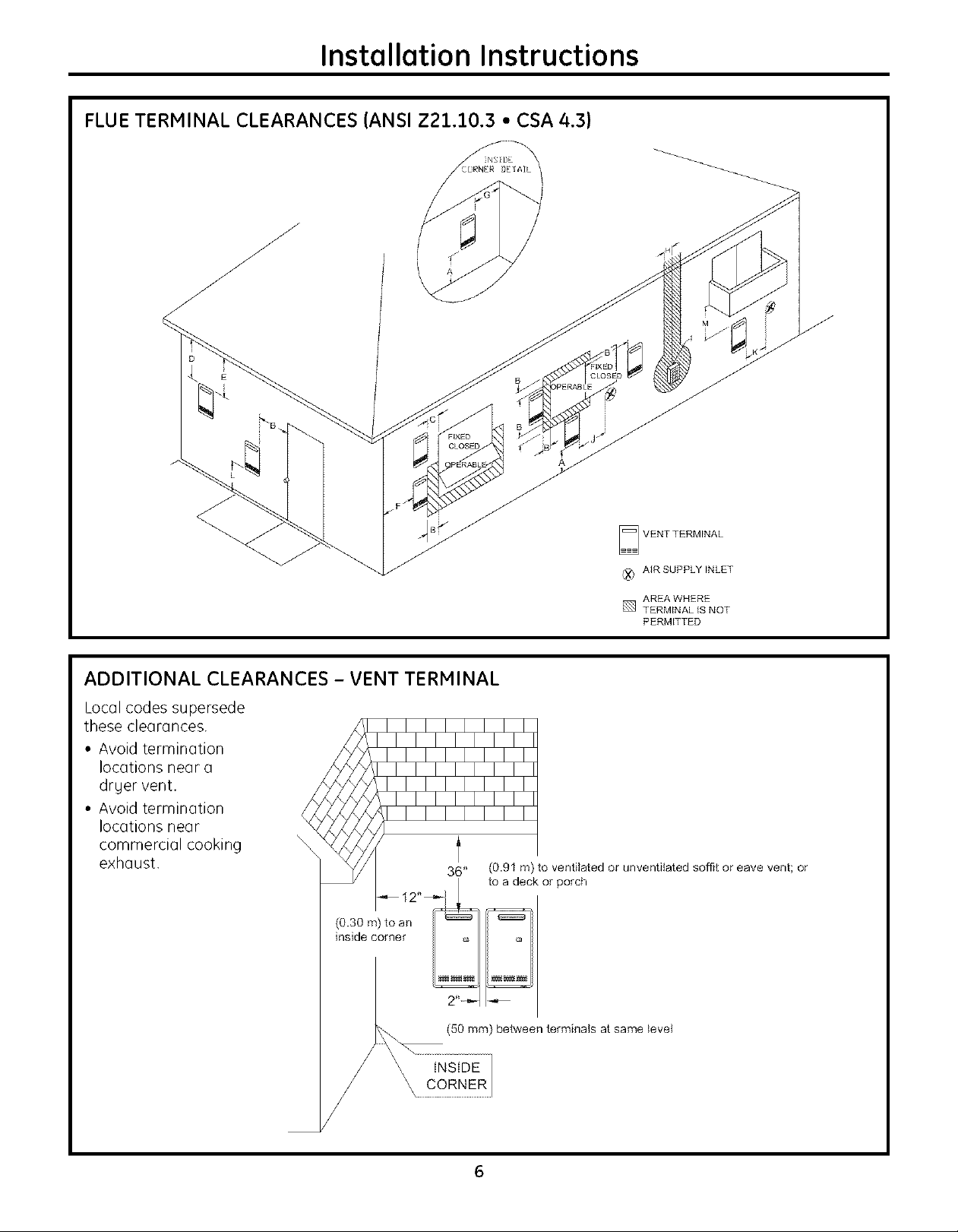
FLUE TERMINAL CLEARANCES
U.S. INSTALLATIONS
CLEARANCES PER
REF DESCRIPTION ANSI Z21.10.3
A Clearance above grade, veranda, porch, deck or snowline 36 inches (91 cm)
B Clearance to window or door that mag be opened 12 inches (BOcm)
C Clearance to permanentlg closed window *
D Vertical clearance to ventilated soffit, located above the terminal *
within a horizontal distance of 2 feet (61 cm) from the center line
of the terminal
E Clearance to unventilated soffit *
F Clearance to outside corner *
G Clearance to inside corner *
H Clearance to each side of center line extended above meter/regulator *
assemblg
I Clearance to service regulator vent outlet *
J Clearance to nonmechanical air supplg inlet to building or 12 inches (BOcm)
the combustion air inlet to ang other appliance
K Clearance to a mechanical air supplg inlet 3 feet (91 ca) above
ifwithin 10 feet
(3m) horizontallg
L Clearance above paved sidewalk or paved drivewag located *
on public propertg 1
M Clearance under veranda, porch, deck or balcong2 *
*For clearances not specified in ANSI Z223 1/NFPA 54, clearances are in accordance with local installation codes and the requirements of the gas
supplien Clearance to opposite wall is 24 inches (60 crn)
1 A vent shall not terminate dkectlg above a sidewalk or paved drivewag that is located between two single familg dwellings and serves both
dwellings.
2 Permitted onlg ifveranda, porch, deck or balcong is fullg open on a minimum of two sides beneath the floor
5
Page 6
Installation Instructions
FLUE TERMINAL CLEARANCES (ANSI Z21.10.3 • CSA 4.3)
NSiDE
DETAIL
ADDITIONAL CLEARANCES - VENT TERMINAL
Local codes supersede
these clearances.
• Avoid termination
locations near a
drger vent.
• Avoid termination
locations near
commercial cooking
exhaust.
(0.30 m) to an
inside corner
36" (0.91 m) to ventilated or unventilated soffit or eave vent; or
to a deck or porch
VENT TERMINAL
{X} AIR SUPPLY INLET
[] AREA WHERE
TERMINAL IS NOT
PERMITTED
6
Page 7

PLANNING FOR PLUMBING
(shown with optional pipe cover)
Installation Instructions
6[ound
The center of the p,pes can be placed anuwhere
within the shaded area. The center of the pipes
is recommended to be protruding only within 6"
of the mounting wall. Other specific installations
ma U be different.
Be sure that the minimum elevation of the bottom
of the unit is 18" to meet the 36" recommended
clearance for the exhaust.
CAUTION: BURN HAZARD. Hot exhaust and
vent mou cause serious burns. Keep back from water
heater unit. Keep small children and animals owou
from unit.
x Suggestedarea for Water and GaslinestQcome
throughthe waEEto aEEowtheoptionalpipe cQ_er
tQbe installed if desired
CAUTION:Hot Water outlet pipes leaving unit
can be hot to touch. Insulation must be used for hot
water pipes below 36" due to burn risk to children.
NOTE: It is recommended to install the bottom
of the unit at least 18" off the ground to minimize
blockage and maintenance from debris and provide
room for the optional Pipe Cover Accessoru Model
Number AGTPCM.
NOTE: Do not install electrical outlet directl U
below unit. Electrical outlet must be installed
less than 6 feet from unit.
?
Page 8
Installation Instructions
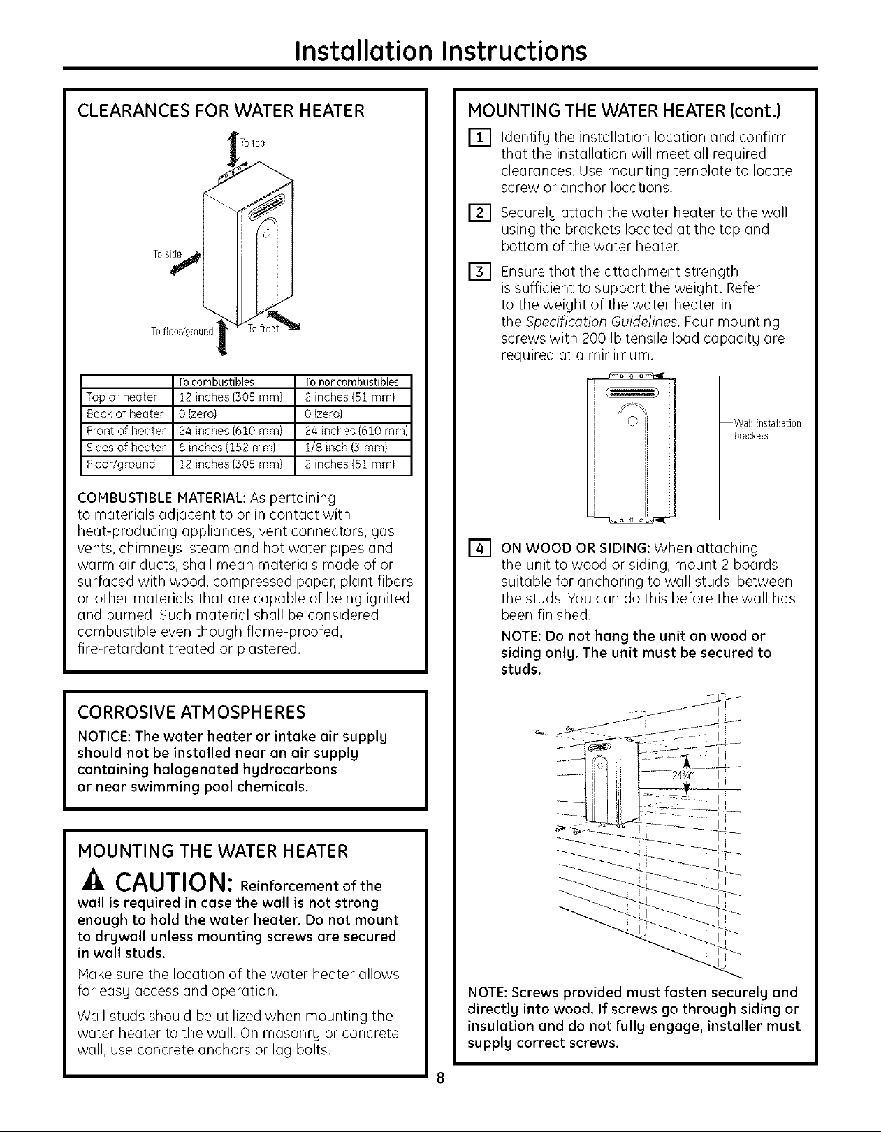
CLEARANCES FOR WATER HEATER
Toside
Tofl0or/ground
Tocombustibles Tononcombustibles
Top of heater 12 inches (305 mm} 2 inches (51 mm}
Back of heater 0 (zero) 0 (zero)
Front of heater 24 inches {610 mm) 24 inches {610 mml
Sides of heater 6 inches (152 mm} 1/8 inch (3 mm}
Floor/ground 12 inches {305 mm) 2 inches {51 mm}
COMBUSTIBLE MATERIAL: As pertaining
to materials adjacent to or in contact with
heat-producing appliances, vent connectors, gas
vents, chimneys, steam and hot water pipes and
warm air ducts, shall mean materials made of or
surfaced with wood, compressed paper, plant fibers
or other materials that are capable of being ignited
and burned. Such material shall be considered
combustible even though flame-proofed,
fire-retardant treated or plastered.
MOUNTING THE WATER HEATER (cont.)
[] Identify the installation location and confirm
that the installation will meet all required
clearances. Use mounting template to locate
screw or anchor locations.
[]
Securely attach the water heater to the wall
using the brackets located at the top and
bottom of the water heater.
[]
Ensure that the attachment strength
is sufficient to support the weight. Refer
to the weight of the water heater in
the Specification Guidelines. Four mounting
screws with 200 Ib tensile load capacity are
required at a minimum.
Wall installation
brackets
[] ON WOOD OR SIDING: When attaching
the unit to wood or siding, mount 2 boards
suitable for anchoring to wall studs, between
the studs. You can do this before the wall has
been finished.
NOTE: Do not hang the unit on wood or
siding only. The unit must be secured to
studs.
CORROSIVE ATMOSPHERES
NOTICE: The water heater or intake air supply
should not be installed near on air supply
containing hologenated hydrocarbons
or near swimming pool chemicals.
MOUNTING THE WATER HEATER
-A CAUTION: Reinforcementofthe
wall is required in case the wall is not strong
enough to hold the water heater. Do not mount
to drywall unless mounting screws are secured
in wall studs.
Hake sure the location of the water heater allows
for easy access and operation.
Wall studs should be utilized when mounting the
water heater to the wall. On masonry or concrete
wall, use concrete anchors or lag bolts.
NOTE: Screws provided must fasten securely and
directly into wood. If screws go through siding or
insulation and do not fully engage, installer must
supplg correct screws.
8
Page 9

Installation Instructions
MOUNTING THE WATER HEATER (cont.)
ON MASONRY OR CEMENT WALL: Mount
/4wall anchors (not supplied) suitable to
carr U 200 Ibs minimum tensile load each.
Level the unit during installation.
IMPORTANT: Anchors suitable for masonr Uor
concrete are to be supplied bu the installen
9
Page 10

Installation Instructions
CONNECTING THE WATER HEATER TO GAS AND WATER
[] GAS PIPING
GENERAL INSTRUCTIONS
• Hake sure gas supply is off prior to making
any connections to the water heaten A manual
gas control valve, provided with this water
heater, must be placed in the gas supply line
to the water heaten A union can be used on
the connection above the shut-off valve for
the future servicing or disconnection of the unit.
• Check the type of gas and the gas inlet pressure
before connecting the water heater. If the water
heater is not of the gas type that the building is
supplied with, DO NOT connect the water heater.
Contact the dealer for the proper unit to match
the gas type.
• Check the gas supply pressure immediately
upstream at a location provided by the gas
company. Supplied gas pressure must be within
the limits shown in the Specifications section.
• Before placing the appliance in operation, all
joints, including the heater, must be checked for
gas tightness by means of leak detector solution,
soap and water or an equivalent nonflammable
solution, as applicable. (Since some leak test
solutions, including soap and water, may cause
corrosion or stress cracking, the piping shall
be rinsed with water after testing, unless it has
been determined that the leak test solution is
noncorrosive.)
• Always use approved connectors to connect the
unit to the gas line. Always purge the gas line of
any debris before connection to the water heater.
• The gas supply line shall be gas tight, sized
and so installed as to provide a supply of gas
sufficient to meet the maximum demand of the
heater and all other gas-consuming appliances
at the location without loss of pressure.
• Any compound used on the threaded joint of
the gas piping shall be a type which resists the
action of liquefied petroleum gas (propane/LPG).
• Refer to an approved pipe sizing chart
if in doubt about the size of the gas line.
[] GAS PIPING (cont.)
PIPE SIZING PROCEDURE
The gas supply to the home must be capable
of handling the entire gas load of the home,
calculated by adding the BTU rating of each gas
appliance in the home. State and local codes must
be met, as well as utility requirements, to ensure
gas supply to the unit is adequate to meet the
rated demand. Use the charts below as a guide to
size the pipe from the utility meter to the tankless
water heaten Gas line sizing is based on gas type,
the pressure drop in the system, the gas pressure
supplied and the gas line type. Refer to the Notional
Fuel Gas Code, NFPA 5/4,and/or your local gas
provider, for proper gas line sizing.
PIPE SIZING TABLE - NATURAL GAS
cubic feet per hour Schedule40 Metallic Pipe
Inlet Pressure: less than 2 psi (55 inches W.C.}
Pressure Drop: 0.3 inches W.C.
Specific Gravitg: 0.60
PIPE SIZE (INCHES)
Length 3/4 1 11/4 11/2
I0 273 514 1060 1580
20 188 353 726 1090
30 151 284 583 873
40 129 243 499 747
SO 114 215 442 662
60 104 195 400 600
70 95 179 368 552
80 89 167 343 514
90 83 157 322 482
i00 79 148 304 455
125 70 131 269 403
iSO 63 119 244 366
175 58 109 224 336
200 54 102 209 313
PIPE SIZING TABLE - PROPANE GAS
cubic feet per hour Schedule 40 Metallic Pipe
Inlet Pressure: ii.0 inches W.C.
Pressure Drop: 0.5 inches W.C.
Specific Gravitg: 1.50
PIPE SIZE (INCHES)
Length 1/2 3/4 1 11/4
i0 291 608 i150 2350
20 200 418 787 1620
30 160 336 632 1300
40 137 287 541 iii0
50 122 255 480 985
60 ii0 231 434 892
80 101 212 400 821
I00 94 197 372 763
125 89 185 349 716
ISO 84 175 330 677
175 74 155 292 600
200 67 140 265 543
i0
Page 11

Installation Instructions
CONNECTING THE WATER HEATER
TO THE GAS SUPPLY
Connect the gas supply to the system following
state and local plumbing codes. Use the supplied
ball valve at the inlet to the system. Hake sure
the gas supply line to the water heater fits in the
diagram shown on page 7. This is essential if a pipe
cover accessory (model number AGTPCH) is to be
installed.
IMPORTANT: Use a pipe wrench to securely
hold on to the end of the water heater gas inlet
to prevent twisting the inlet.
IMPORTANT: Leave the gas valve off until
instructed to turn it on.
11
Page 12

Installation Instructions
CONNECTING THE WATER HEATER TO GAS AND WATER (cont.)
[] WATER PIPING
GENERAL INSTRUCTIONS
• The water supplg should be shut off while
connecting the water heaten Make sure the
water inlet and outlet lines to the water heater fit
in the diagram shown on page 7. A manual water
control valve must be placed in the water inlet
connection to the water heater before it is
connected to the water line. Unions can be
used on both the hot and cold water lines for
future servicing and disconnection of the unit.
• The piping (including soldering materials) and
components connected to this appliance must
be approved for use in potable water sgstems.
• Purge the water line to remove all debris and ain
Debris will damage the water heaten
• Toxic chemicals such as those used for boiler
water treatment are not to be introduced to the
potable water used for space heating.
• If the appliance will be used as a potable water
source, it must not be connected to a sgstem
that was previouslg used with a nonpotable
water heating appliance.
• Ensure that the water filter on the water heater
is clean and installed. See the Cleaning the inlet
filter section on page 19.
• New plumbing tgpicallg has contamination
in the lines. The inlet water filter should be
cleaned immediatelg after initial use.
CAUTION:Hot Water outlet pipes leaving
unit can be hot to touch. Insulation must be used
for hot water pipes below 36" due to burn risk to
children.
[] WATER PIPING (cont.)
PRESSURE RELIEF VALVE (cont.)
• The relief valve must be rated up to 150 psi and
to at least the maximum BTU/hr of the appliance.
• The discharge from the pressure relief valve
should be piped to the ground or into a drain
sgstem to prevent exposure or possible burn
hazards to humans or other plant or animal life.
Follow local codes. Water discharged from the
relief valve could cause severe burns instantlg,
scalds or death.
• The pressure relief valve must be manuallg
operated once a gear to check for correct
operation.
• The relief valve should be added to the hot water
outlet line according to the manufacturer's
instructions. DO NOT place ang other tgpe of
valve or shut-off device between the relief valve
and the water heaten
• Do not plug the relief valve and do not install ang
reducing fittings or other restrictions in the relief
line. The relief line should allow for complete
drainage of the valve and the line.
• If a relief valve discharges periodicallg, this mag
be due to thermal expansion in a closed water
supplg sgstem. Contact the water supplier or
local plumbing inspector on how to correct this
situation. Do not plug the relief valve.
• Neither GE nor the American National Standard
{ANSI Z21.10.3)/Canadian Standard {CSA 4.3)
requires a combination temperature and
pressure relief valve for this appliance; however,
local codes mag require a combination
temperature and pressure relief valve.
PRESSURE RELIEF VALVE
• Hake sure the pressure relief valve is installed
so there is clearance if the optional pipe cover
(AGTPCH) is installed.
• An approved pressure relief valve is required
bg the American Notional Standard (ANSI
Z21.10.3)/Conadian Standard (CSA 4.3)
for all water heating sgstems.
• The relief valve must complg with the standard
for Relief Valves and Automatic Gas Shutoff
Devices for Hot Water Supply S_]stems (ANSI
Z2J.22) and/or the standard Temperature,
Pressure, Temperature and Pressure Relief
Valves and Vacuum Relief Valves, CANJ-4.4.
INTERNAL BUILT-IN FREEZE PROTECTION
• The freeze protection features include
electrical heating elements and intermittent firing
of the burnen Freeze protection mag be disabled
if electricitg or gas is not supplied, or if there is
an error preventing the water heater from
functioning.
NOTE: See Supplemental Freeze Protection
on page 13.
12
Page 13

Installation Instructions
CONNECTING THE WATER HEATER
TO THE WATER SUPPLY
H0tOutlet :_
/
Water connections to the tankless water heater
should follow all state and local plumbing codes.
If this is a standard installation, refer to
the diagram on the following page under
RECOMMENDED PIPING FOR BASIC INSTALLATION.
If freeze protection valves are being installed, refer
to the diagram under FREEZEPROTECTION FOR
EXTERNAL PIPING on page 15.
SUPPLEMENTAL FREEZE PROTECTION
If the unit is installed in an environment that can
freeze, follow state and local codes and appl9 heat
trace to ALL water pipe and fittings located outside
{attic, crawl space or building structure).
It is highlg recommended in areas where freezing
temperatures occur to install automatic drain
valves that work in the event of a power loss.
Refer to the diagram in the FREEZEPROTECTION
FOR EXTERNAL PIPING section (page 15). These
valves should be wired to a supplg current.
In the event of a power loss, the sgstem will
drain automaticall9. Be sure to test this sgstem
after installation b9 turning off power to ensure
the sgstem drains properlg.
1. Plumb water suppl9 to the tankless water heater
on the 3/4" MNPT connection at the bottom of
the unit marked WATER INLET.
2. Plumb the home hot water suppl9 to the 3/4"
MNPT connection marked WATER OUTLET
at the bottom of the unit.
NOTE: Hake sure water lines to the water heater fit
in the diagram shown on page 7. This is essential if
a pipe cover accessor U{model number AGTPCH) is
to be installed.
13
Page 14

Installation Instructions
RECOMMENDED PIPING FOR BASIC INSTALLATION
I_o @ o% j
o o
NOTE:If unit is installed in an
environment that con freeze,
follow state and local codes
and appl 9 heat trace to ALL
water pipes and fittings
located outside (attic, crawl
space or building structure}.
Water Heater
Equipment List QTY
Water Heaters 1
(Optional)
3/4" Fittings Include:
Unions 2
Ball Valves 2
Drain Valves 2
Pressure Relief Valve 1
o o
3/4" Gas Connection
__(_1 3/4" Ball Valve
I
3/4" Union
3/4" Hot Water Supply Line
For Building Fixtures
KEY
I_ Boiler Drain Valve
Pressure Relief Valve
Gas Supply
3/4" Cold Water Supply Line
This is not an engineered drawing; it is intended
onlg as a guide and not as a replacement for
professionallg engineered project drawings. This
drawing is not intended to describe a complete
sgstem; it is up to the contractor/engineer to
determine the necessarg components for and
configuration of the particular sgstem being
installed. The drawing does not implg compliance
with local building code requirements; it is the
engineer's/contractor's responsibilitg to ensure
the installation is in accordance with all local
building codes. Confer with local building officials
before installation.
14
Page 15

FREEZE PROTECTION
FOR EXTERNAL PIPING
Installation Instructions
Vacuum
Breaker
IMPORTANT!
With electrical power supplied to the water
heater, it will not freeze in environments as
cold as -30°F, when protected from direct wind
exposure.
In the event of a power failure at temperatures
below freezing, the water heater should be
drained of all water to prevent freezing damage.
The unit mau be drained manuallu, or through
the installation of the optional solenoid valves
as shown.
The unit mau be drained manuallu; however, we
highlu recommend that drain-down solenoid valves
be installed that will automaticallu drain the unit if
power is lost.
When the electrical power to the water heater
fails, the 3/4" solenoid valve closes (stopping
the flow of water into the heater) and the 1/4"
solenoid valve opens (allowing the water heater
and associated piping to drain). Ensure that Uou
run the drain for the solenoids to the outside
environment to prevent discharging water inside
the building, which can cause water damage.
NOTE: If the unit is installed in an environment that
can freeze, follow state and local codes and applu
heat trace to ALL water pipes and fittings located
outside (attic, crawl space or building structure).
o q
Water Heater
\
Equipment List QTY
Water Heaters
(Optional)
3/4" Fittings Include:
Unions 2
BallValves 2
Drain Valves 2
Pressure Relief Valve
3/4" Gas Connection
I(_- 3//4" Bull Valve
3//4" Union
c_..j Check Valve
z_ Pressure Relief Valve
NOTE:
All pipes and fittings shown
in the dashed boxes should
be located where they will
not freeze, Suggest inside
home or building structure.
KEY
Pressure Regulator
I.k_ Circulating Pump
I_h_ Boiler Drain Valve
[_ Solenoid Valve
Minimum 3/4" Hot Water
Supply Line
L •..............................................................
3/4" Minimum Minimum 3/4"
Normally Closed Cold Water
1/4" Minimum
Normally Open
Solenoid Valve
Solenoid Valve Supply Line
Route to Floor Drain
This is not an engineered drawing; it is intended
onlu as a guide and not as a replacement for
professionallu engineered project drawings. This
drawing is not intended to describe a complete
sustem; it is up to the contractor/engineer to
determine the necessaru components for and
configuration of the particular sustem being
installed. The drawing does not implu compliance
with local building code requirements; it is the
engineer's/contractor's responsibility to ensure
the installation is in accordance with all local
building codes. Confer with local building officials
before installation.
15
Page 16

Installation Instructions
[] ELECTRICAL CONNECTION
INFORMATION
A WARNING - Toreducetherisk
of fire, electrical shock and personal injury:
The water heater must be electricallg grounded
in accordance with local codes and ordinances
or, in the absence of local codes, in accordance
with the NATIONAL ELECTRICALCODE, ANSI/NFPA
NO. 70, or the CANADIAN ELECTRICALCODE,
CSA C22.1.
ELECTRICAL REQUIREMENTS
This appliance must be supplied with 120V, 60Hz,
and connected to a properlg grounded branch
circuit, protected bg a 15- or 20-amp circuit
breaker or time-delag fuse.
If electrical supplg provided does not meet the
above specifications, it is recommended that a
licensed electrician install an approved outlet.
Wire nuts
Outsideunit
120VAC CONNECTION WIRES
(Black-Hot/White-Neutral)
Electrical
i Ebctdcal" disconnect
-- switch
16
Page 17

Installation Instructions
HIGH ALTITUDE INSTALLATIONS
Set dip switches 2 and 3 to the values shown in the
table below for gour altitude. The default setting for
the appliance is 0-2000 ft (0-610 m) with switches
No. 2 and No. 3 in the OFF position.
0-2000 ft. 2001-5200 ft. 5201-7700 ft. 7701-10200 ft.
(0-610 m) (610-1585 m) (1585-2347 m) (2347-3109 m)
Switch No. 2
E
Switch No. 3
OFF ON
OFF
OFF
ON
WARNING: Do not adjust the other
dip switches unless specifically instructed to do so.
If unsure of the altitude in your location, call
1.888.HOTWTER (888.467.9837).
ON
OFF
ON
Switch No.
O 1
i-
I
J
,__ Im 3
L--
ON
4
5
6
7
8
Switch No.
O ---- 1
im 3
CASCADING MULTIPLE WATER HEATERS
The Dual Connect Cable Kit (AGTDC1) is an optional
accessorg that connects 2 water heaters and allows
them to function as one hot water source.
The Multi Connect Kit (AGTCK1)and the Multi Connect
Cable Kit (AGTMC1) are optional accessories that
connect 3 to 5 water heaters and allow them to
function as one hot water source.
Refer to the instructions that come with the accessor9
for complete installation information.
ON
Switch No.
ON
O I
F _2
m m
4
5
6
7
8
4
5
6
7
8
0 ----
F
_liT
Switch No.
GUIDELINES
• Do not install the Dual Connect Cable Kit (AGTDCI)
with the Hulti Connect Kit (AGTCKI) and the Hulti
Connect Cable Kit (AGTHC1) because theg are not
designed to operate togethen
• Water heaters should be installed less than
18 inches apart so that the cables will reach
between units and to prevent temperature
fluctuations (cold water sandwich effect) when
the water is shut off and turned back on.
ON
1
i
J
_J
4
5
6
7
8
• Temperature settings can onlg be changed on
the controller for the primarg unit.
NUMBEROF CONNECTEDWATERHEATERS ACCESSORIESNECESSARY
2 (1}Dual Connect Cable Kit (AGTDC1}
3 (1) Multi Connect Kit (AGTCK1)and (1)Multi Connect Cable Kit(AGTMC1)
/4 (1)Multi Connect Kit (AGTCK1)and (2)Multi Connect Cable Kits(AGTMC1)
5 (1)Multi Connect Kit (AGTCK1)and (3)Multi Connect Cable Kits(AGTMC1)
ConnectingTwoUnits
ConnectingFiveUnits
17
Page 18

Installation Instructions
REMOTE CONTROLLER INSTALLATION
LOCATION
• The controller should
be out of reach of small
children.
• Avoid locations where
the controller may
become hot (near the
oven or radiant heater).
• Avoid locations in direct
sunlight. The digital
display may be difficult
to read in direct
sunlight.
• Avoid locations where the remote controller
could be splashed with liquids.
• Do not install in locations where it can be
adjusted by the public.
CONFIGURATIONS
A maximum of 4 remote controllers can be
installed for a water heater or bank of water
heaters. Controllers can only be wired in parallel.
Controllers cannot be wired in series.
F/0
!iii_i_iii?(iiiii
<-,o0,9
REMOTECONTROLLER INSTALLATION
(cont.}
MOUNTING THE CONTROLLER
[] Determine a suitable location for
the controllen
[] Mount a single gang outlet box in the wall
where the remote control is indicated.
[] Run the cable between the controller
and the water heater or the controller
and the other controllen
[] Remove the face plate from the remote
controller, using a screwdriven
[] Connect the cable to the remote controllen
[] Mount the controller to the wall in the single
gang outlet box installed in step 2.
[] Disconnect the power from the water heaten
[] Remove the cover of the water heaten
[] Remove the plastic cover from the PCB
and electrical connections.
Outline of Remote
If 4 AGTRCI's are installed, press the Priority and
On/Off buttons on the fourth controller until a beep
sounds.
i f%
i ,J
Wire Controllersin Parallel
CABLE LENGTHS AND SIZE
The cable for the remote controller should be
a nonpolarized two-core cable with a minimum
gauge of 22 AWG. The maximum cable length
from each controller to the water heater depends
on the total number of wired controllers connected
to the water heaten
Controllers
/
i
securing screw
1-21/32"
wiring hole
securing screw
3-5/16"
A WARNING: DONOTATTEHPT
TO CONNECT THE REMOTECONTROLLERSWITH
THE POWER ON.
NUMBEROF WIRED MAXIMUM CABLE LENGTH FOREACH
CONTROLLERS CONTROLLERTO WATERHEATER
1 328 ft. {100 m}
2 164ft.(50m}
5 or 4 65 ft{20 m}
18
Page 19

Installation Instructions
REMOTECONTROLLERINSTALLATION(cont.)
MOUNTING THE CONTROLLER (cont.)
[] Threadthe cablethrough the access holeat the base
of the unit and connect the wiresto the controller
terminals on the bottom right-hand side of the PCB.
[] Securethe controller cableusing the clamp provided.
[] Replacethe plasticcover over the PCB,and then
replacethe cover ofthe water heater.
REMOTE CONTROL
CONNECTION TERMINALS
CLEANINGTHE INLETFILTER
It isimperative that Waterinlet
control compartments, "_
burners and circulating
air passagewaysof the
appliance be keptclean.
CAUTION:Before
performing this action,first
remove power to the water NOTE:Vievvshown
heater and be sure not to _ isfromundertheunit
stand near the discharge line ofthe pressurereliefvalve.
Thiswill prevent a possiblescald injury.
[] Turn off and disconnect electricalpowe[ Allowwater
heater to cool.
[] Shut off water inlet.
[] Open hot water tap at nearest faucet.
[] Closeoutlet valve on unit.
[] Have a small pan or bucket ready to catch spilled
wate[
[] Remove and clean the water inlet filter with a small
brush. If scale ispresent, clean in a white vinegar
solution.
[] Replacewater inlet filter.
[] Removethe front panel by removing/4screws.
CLEANINGTHE INLETFILTER(cont.)
[] Use pressurizedair to remove dust from the main
burner,heat exchanger and fan blades.Donot usea
wet cloth or spray cleaners on the burne[ Donot use
volatile substances such as benzeneand thinners.
They may ignite or fade the paint.
[] Usesoft dry cloth to wipe cabinet.
[] Open water valves.
[] Checkfor leaks.
[] Connect electrical power and turn on the unit.
INSTALLATIONCHECKLIST
• Ensure120VoltsA.C isconnected to the unit and that
the circuit isturned on.
• Verify the gassystem isfunctioning correctly by
connecting your manometer to the gas pressuretest port
on the unit (seepage 11}.Operate all gas appliances in
the facility. Theinletgas pressureon the unit MUSTNOT
DROPBELOWthat listedon the unit rating plate for the
gastype beingused.A manometer can be used to check
the pressure.
• Hake sureyou havecleaned the COLDwater inlet filter
screen.
• Inspect HOT(outlet)and COLD(inlet)water linesto ensure
they have not been crossedand are leak-free.
• Ensurethe manual gas valve packaged with the water
heater isinstalled in the gas supply line (seepage 10).
• Ensurethe controller isinstalledand functioning.
Instruct the consumer on how to operate the controller.
Instructions are always suppliedin the Owner's Manual
(seepage 18}.Atypical water temperature set point
is 120degrees.
• Forinstructions on operating the unit, referto the Owner's
Manual.
19
Page 20

TECHNICAL DATA
PRESSUREDROP CURVE
3O
Installation Instructions
25
20
O_
O9
03
o
J 15
_ lO
5
0.0 2.0
OUTLET FLOW DATA
6N75 ]
/
/
I
4.0 6.0 8.0
Water Flow (gpm)
_ GN941GP94 6O
5O
40 "_
30 _
2O
10
10.0
(D
-C:
09
0
J
03
O')
D...
o
10 i
I
I
9
I
I
8 I
E I ,
7
03 i
I
_o I
LL i
4 I
-4-, I
3 i
-r- 2 I
0 i p
1 1
0
I
I
I
I
I
I
I
I
\
m
m
25 50 75 100 125
\
\X
\
\
%\
\
I I I P
i i
150
delta T - Temperature Rise (°F)
2O
Page 21

Installation Instructions
LADDER DIAGRAM
3A(FUSE)
ARR_STER
G_4D
HOT
FROSTSENSING
I
I
I
I
+
SWITCHING j]
POWERSUPPLY
NEUTRAL
ANTI-FROSTHEATER
IGNITION
I
I J
INDOORMODELONLY
21
Page 22

Notes
22
Page 23

Notes
23
Page 24

Notes
24
 Loading...