

Page 1
Installation
Indoor Direct Vent Tankless Water Heater
Models GN75DNSRSA, GN94DNSRSA, GP94DNSRSA
Instructions
FOR INDOOR APPLICATIONS ONLY
Questions? Call 888.HOTWTER (888.468.9837) or Visit our website at ge.com
WARNING: Read entire manual. Failure to follow all guides and rules could cause personal
injury or property damage.
• Check with your state and/or local public works department for plumbing codes. You must follow their
guides as you install the Water Heater.
NOTE: Failure to comply with these installation instructions will void the product warranty, and the
installer will be responsible for any service, repair or damages caused thereby.
BEFORE BEGINNING INSTALLATION
Read these instructions completely and carefully.
•
IMPORTANT — Save these instructions
for local inspector’s use.
•
IMPORTANT — Observe all governing
codes and ordinances.
• Note to Installer – Be sure to leave these
instructions with the Consumer.
• Note to Consumer – Keep these instructions
for future reference.
• Proper installation is the responsibility of the
installer.
• Product failure due to improper installation
is not covered under the Warranty.
Recognize this symbol as an indication
of Important Safety Information!
49-50229-1 03-08 JR
SAFETY PRECAUTIONS
WARNING: If the information in these
instructions is not followed exactly, a fire or explosion
may result, causing property damage, personal injury
or death.
FOR YOUR SAFETY!
– Do not store or use gasoline or other
flammable vapors or liquids or other
combustible materials in the vicinity of this
or any other appliance. To do so may result
in an explosion or fire.
– WHAT TO DO IF YOU SMELL GAS
• Do not try to light any appliance.
• Do not touch any electrical switch;
do not use any phone in your building.
• Immediately call your gas supplier from a
neighbor’s phone. Follow the gas supplier’s
instructions.
• If you cannot reach your gas supplier,
call the fire department.
• Do not return to your home until authorized
by the gas supplier or fire department.
– Improper installation, adjustment, alteration,
service or maintenance can cause property
damage, personal injury or death. Refer to
this manual. Installation and service must
be performed by a qualified installer, service
agency or the gas supplier.
• This water heater must be vented outdoors
using approved ducting materials.
• Service information and wiring diagram are
located behind front panel.
• Service must be performed by a qualified
service agency.
• This appliance must be properly grounded and
installed as described in these instructions
1
.
Page 2
Installation Instructions
DANGER
Read and follow water heater warnings and
instructions. If owner’s manual is missing, contact
the retailer or manufacturer.
SAFETY PRECAUTIONS (cont.)
WARNING: Do not use substitute
materials. Use only parts certified with the
appliance.
• This appliance must be installed, inspected and
leak tested by a state- or city-qualified licensed
contractor. It is the responsibility of the person
having the water heater installed to ensure the
installing contractor has proper licenses and
permits for installing water heaters in your
location. GE highly recommends that installers
attend a product knowledge class to ensure
customer satisfaction and warranty coverage.
Failure to comply with state and local codes
pertaining to water heater installations may
void the warranty.
SAFETY PRECAUTIONS (cont.)
The flow of combustion and ventilation air shall
•
not be obstructed.
• This appliance is not suitable for use in an
application such as a pool or spa heater that
uses chemically treated water. (This appliance
is suitable for filling large or whirlpool bath tubs
with potable water.)
• If a water heater is installed in a closed-water
supply system, such as one having a backflow
preventer in the cold water supply line, means
shall be provided to control thermal expansion.
Contact the water supplier or local plumbing
inspector on how to control this situation.
• Should overheating occur or the gas supply fail
to shut off, turn off the manual gas control valve
to the appliance.
• Keep the air intake (at the flue terminal external
to the home) location free of chemicals, such as
chlorine or bleach, that produce fumes. These
fumes can damage components and reduce
the life of your appliance.
• This appliance is not to be installed outdoors.
• The installation must conform with local codes or,
in the absence of local codes, with the National
Fuel Gas Code, ANSI Z223.1/NFPA 54, or the
Natural Gas and Propane Installation Code,
CSA B149.1.
• The appliance and its appliance main gas valve
must be disconnected from the gas supply piping
system during any pressure testing of that
system at test pressures in excess of 1/2 psi
(3.5 kPa) (13.84 in W.C.).
• The appliance must be isolated from the gas
supply piping system by closing its individual
manual shut-off valve during any pressure
testing of the gas supply piping system at test
pressures equal to or less than 1/2 psi (3.5 kPa)
(13.84 in W.C.).
• Carefully follow the venting instructions
beginning on page 19 and in the Maintenance
section in the Owner’s Manual for adequate
combustion and ventilation air.
• The appliance should be located in an area
where water leakage of the unit or connections
will not result in damage to the area adjacent to
the appliance or to lower floors of the structure.
When such locations cannot be avoided, it
is recommended that a suitable drain pan,
adequately drained, be installed under the
appliance. The pan must not restrict combustion
airflow.
CAUTION:DO NOT operate the water
heater if any part of the appliance has been under
water.
CAUTION:BURN HAZARD. Hot exhaust
and vent may cause serious burns. Keep back from
water heater unit. Keep small children and animals
away from unit.
CAUTION:Hot Water outlet pipes leaving
unit can be hot to touch. Insulation must be used
for hot water pipes below 36″ due to burn risk to
children.
WARNING: This unit is not intended
or qualified for use in manufactured homes, mobile
homes or recreational vehicles.
2
Page 3
Installation Instructions
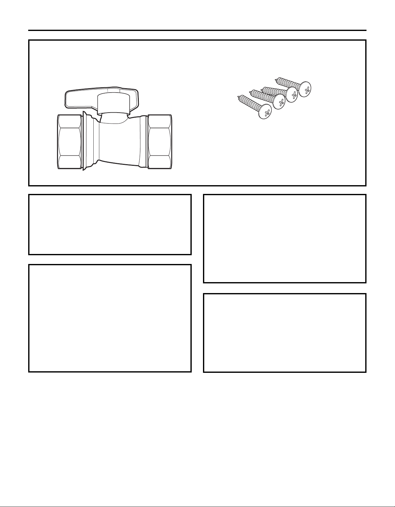
PARTS PROVIDED
ocate the parts packed with the Water Heater.
L
Gas Valve 3/4″ FNPT Ball Valve
4 #10 x 11⁄4″
Wood Screws
TOOLS YOU WILL NEED
• Pipe Wrenches (2) • Gloves
• Adjustable Pliers • Safety Glasses
• Screwdrivers (2)
• Wire Cutters
MATERIALS YOU WILL NEED TO SUPPLY
• Soap Solution • Pipe Fittings Required:
• Pipe Compound – Unions
• Approved Venting – Ball Valves
• 5/8″ ID PVC Flexible – Drain Valves
Tubing
• 2 Conductor 22 AWG Wire for Remote Control
• Single Gang Electrical Box
• Wire Nuts
• Concrete Wall Anchors (Optional)
Your installation components may vary.
– Pressure Relief Valve
OTHER TOOLS THAT MIGHT BE REQUIRED
• Hammer Drill with Concrete Bits
• Saw
• Threading Machine with Heads and Oiler
• Core Drill with Diamond Head
• Torch Set
• Copper Tubing Cutter
• Steel Pipe Cutter
OTHER MATERIALS THAT MIGHT BE NEEDED
• Heat Tape
• Pipe Insulation
• Electrical Wire and Conduit per Local Code
• Air Inlet Screen
• Optional Pipe Cover AGTPCM
• Optional Remote Controller AGTRC1
3
Page 4
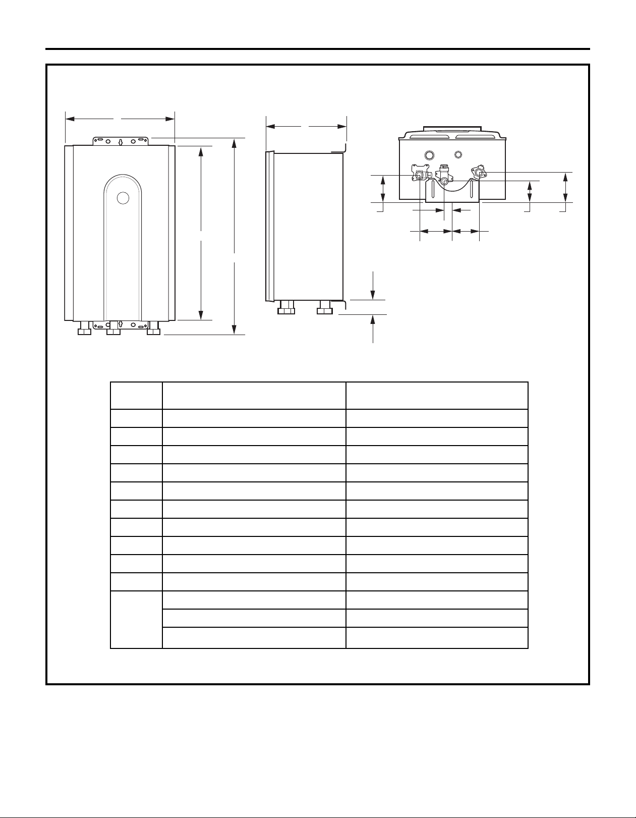
DIMENSIONS
Installation Instructions
A
C
D
B
E
K
H
F
GN75/GN94/GP94DNSRSA
DIM. DESCRIPTION IN. (MM)
G
J
I
A Width 14 (355.6)
B Depth 95⁄8 (244.5)*
C Height – Unit 227⁄8 (582)
D Height – with brackets 251⁄2 (647.7)
E Hot Water Outlet – from wall 35⁄8 (91)*
F Hot Water Outlet – from center 45⁄16 (110)
G Cold Water Inlet – from wall 213⁄16 (70)*
H Cold Water Inlet – from center 11⁄8 (27)
I Gas Connection – from wall 37⁄8 (99)*
J Gas Connection – from center 31⁄2 (89)
From base to gas connection 15⁄8 (40)
K From base to cold connection 2 (50)
5
From base to hot connection 1
*This is the minimum dimension from the wall. The wall bracket is adjustable to allow an additional 1.57 inches (40 mm).
⁄8 (41)
4
Page 5

PLANNING FOR VENTING
INTAKE/EXHAUST GUIDELINES
Installation Instructions
Refer to the specific instructions on your vent
product for additional installation requirements.
• This water heater is a direct vent water heater and
therefore is certified and listed with the vent system.
You must use vent components that are certified
and listed with the water heater model. See
approved venting list on page 20.
• Do not combine vent components from different
manufacturers.
• The vent system must vent directly to
the outside of the building and use outside
air for combustion.
• Every vent connection must be accessible for
inspection, cleaning and replacement.
• Avoid dips or sags in horizontal vent runs by
installing supports per the vent manufacturer’s
instructions.
• Support horizontal vent runs every four feet
and all vertical vent runs every six feet or in
accordance with local codes.
• Venting should be as direct as possible with
a minimum number of pipe fittings.
• Vent diameter must not be reduced.
• Do not connect the venting system with
an existing vent or chimney.
• Do not connect vent with the vent pipe of any other
water heater or appliance.
• Vent connections must be firmly pressed together
so that the gaskets form an air-tight seal.
• The vent piece connected to the water heater must
be secured with one self-tapping screw.
• Refer to the vent pipe manufacturer’s instructions
for component assembly instructions.
• It is recommended to install an optional inlet screen
to minimize blockage and maintenance from debris.
See page 20.
5
Page 6
Installation Instructions
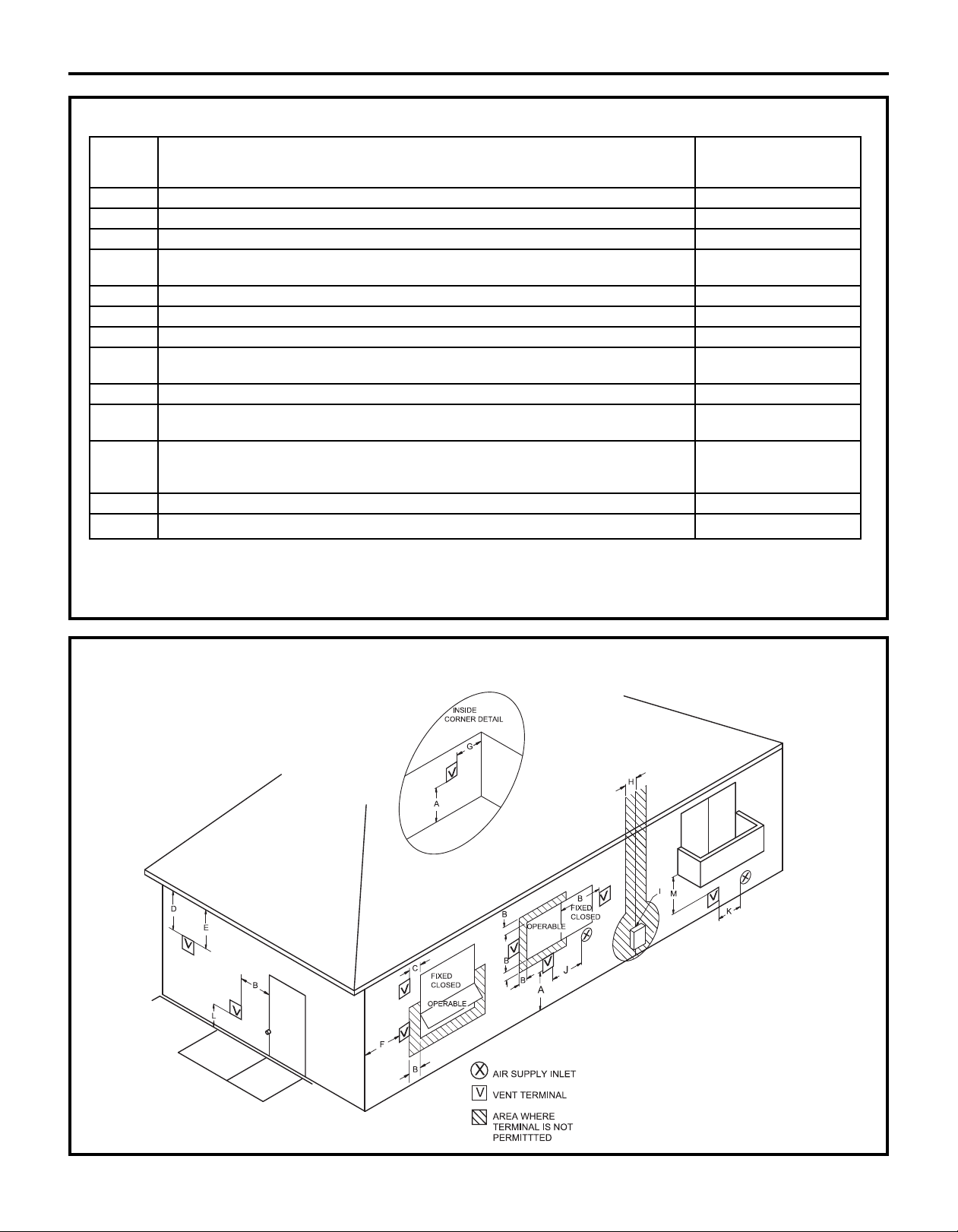
FLUE TERMINAL CLEARANCES
U.S. INSTALLATIONS
CLEARANCES PER
REF DESCRIPTION ANSI Z21.10.3
A Clearance above grade, veranda, porch, deck or snowline 36 inches (91 cm)
B Clearance to window or door that may be opened 12 inches (30 cm)
C
D Vertical clearance to ventilated soffit, located above the terminal within *
E Clearance to unventilated soffit *
F Clearance to outside corner *
G Clearance to inside corner *
H Clearance to each side of center line extended above meter/regulator *
I Clearance to service regulator vent outlet *
J Clearance to nonmechanical air supply inlet to building or 12 inches (30 cm)
K Clearance to a mechanical air supply inlet 3 feet (91 cm) above
L Clearance above paved sidewalk or paved driveway located on public property
M Clearance under veranda, porch, deck or balcony
*For clearances not specified in ANSIZ223.1/NFPA 54, clearances are in accordance with local installation codes and the requirements of the gas supplier.
Clearanceto opposite wall is 24 inches (60 cm).
1 A vent shallnot terminate directly above a sidewalk or paved driveway that is located between two single family dwellings and serves both dwellings.
2 Permitted only if veranda, porch, deck or balcony is fully open on a minimum of two sides beneath the floor.
Clearance to permanently closed window *
a horizontal distance of 2 feet (61 cm) from the center line of the terminal
assembly
the combustion air inlet to any other appliance
if within 10 feet
(3 m) horizontally
1
2
*
*
FLUE TERMINAL CLEARANCES (ANSI Z21.10.3 • CSA 4.3)
6
Page 7
Installation Instructions
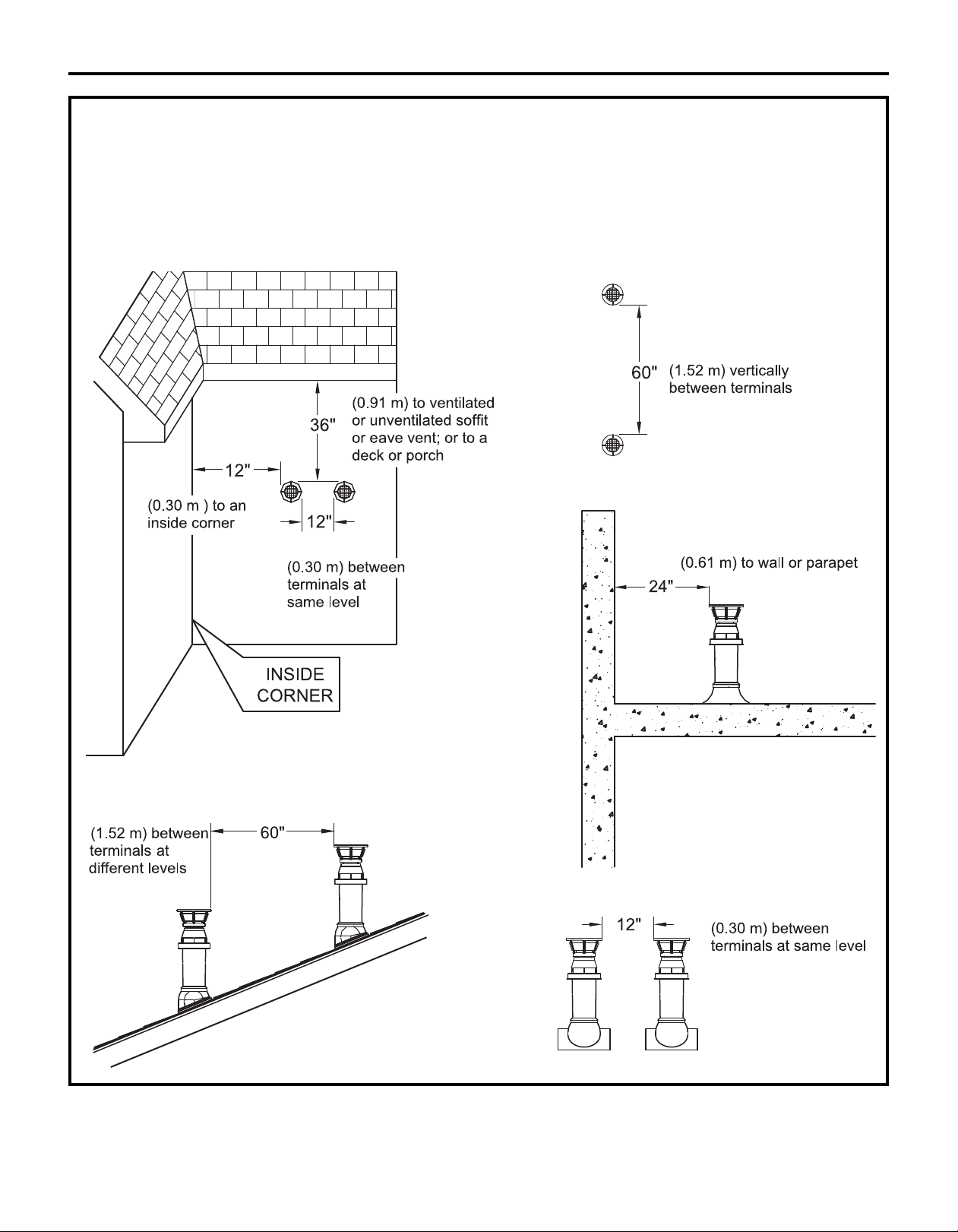
ADDITIONAL CLEARANCES – VENT TERMINAL
hese clearances are applicable to both concentric terminations and nonconcentric vent exhaust terminations.
T
Local codes supersede these clearances.
• Avoid termination locations near a dryer vent.
• Avoid termination locations near commercial cooking exhaust.
7
Page 8
Installation Instructions
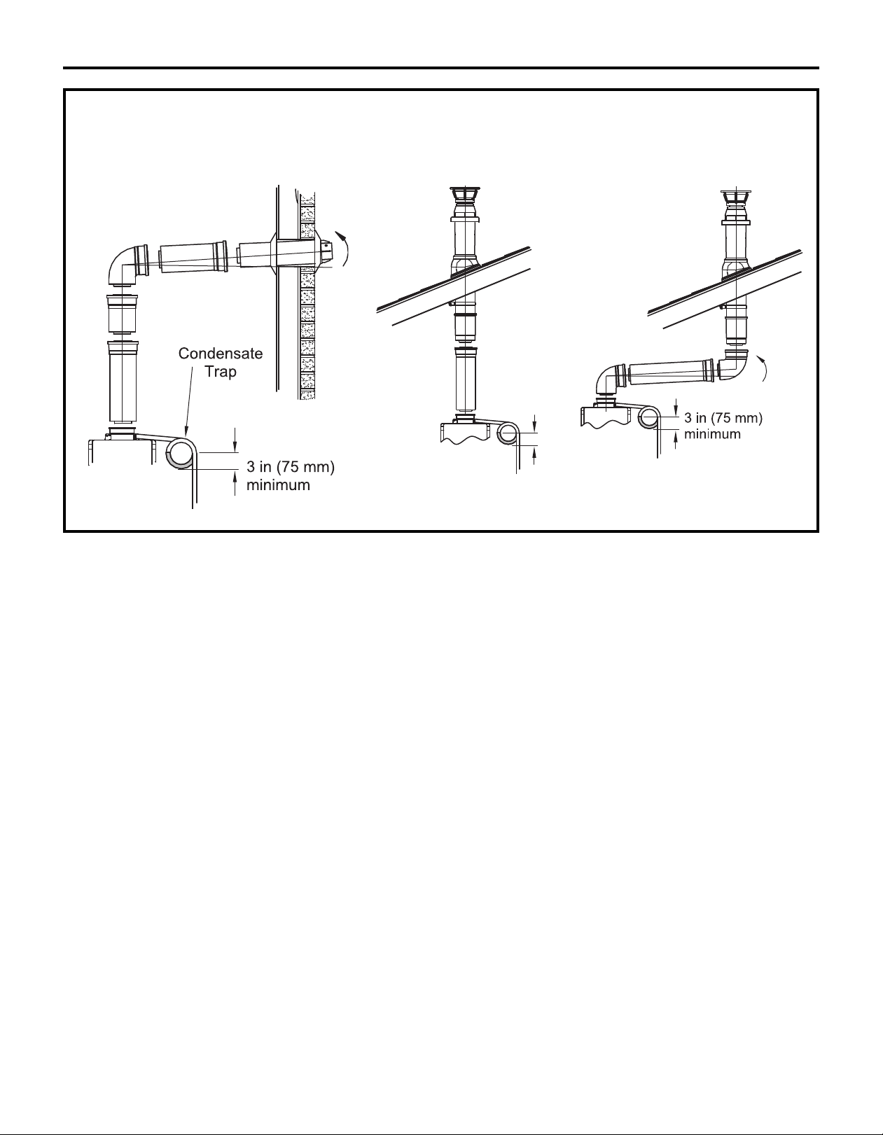
3 in (75 mm)
minimum
FLUE INSTALLATION – CONDENSATE DRAIN
HORIZONTAL TERMINATION WITH VERTICAL TERMINATION (condensate collector
A CONDENSATE DRAIN required in all installations)
8
Page 9
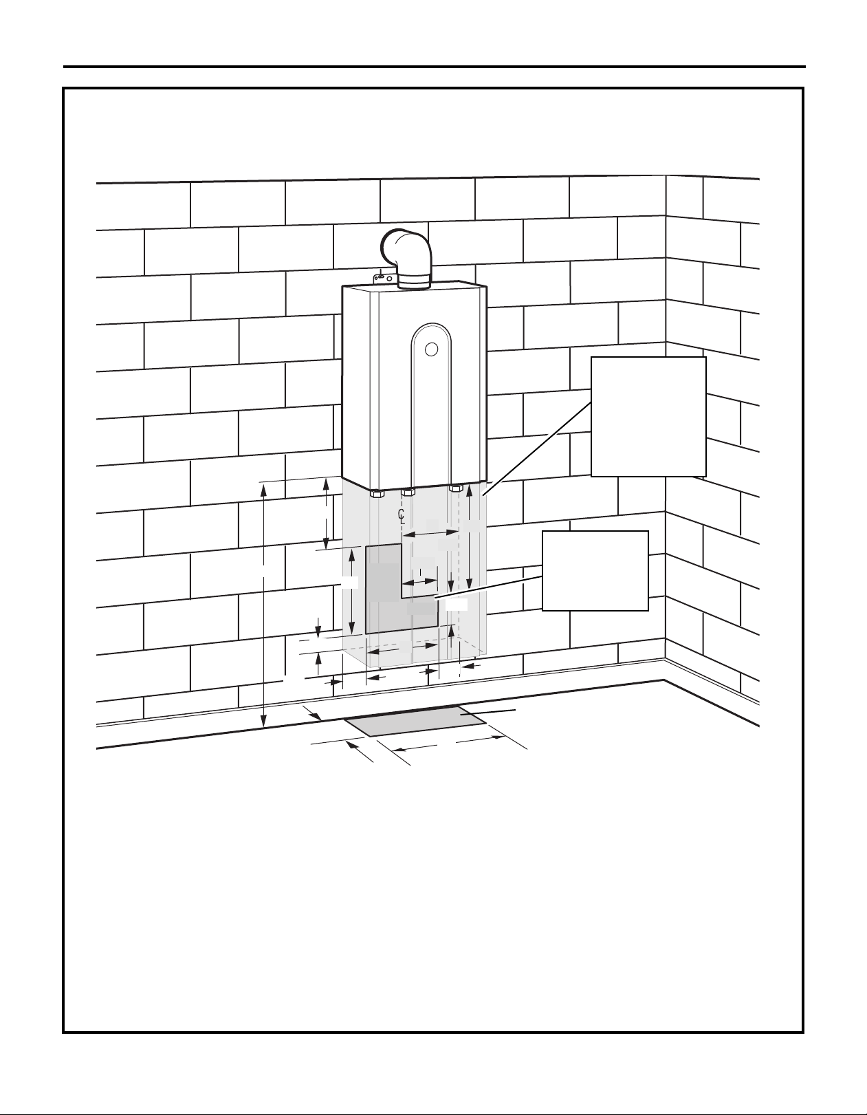
PLANNING FOR PLUMBING
shown with optional pipe cover)
(
Installation Instructions
Unit
Optional Pipe Cover
(AGTPCM) shown shaded.
Pipe cover not required,
However, consideration
should be taken in
the design of the rough
plumbing to allow
installation of unit
and pipe cover.
61⁄2″
18″ min.
21⁄2″
21⁄2″
6″
Floor
97⁄8″
21⁄2″
Water
through
the wall
9″
The center of the pipes can be placed anywhere
within the shaded area. The center of the pipes
is recommended to be protruding only within 6″
of the mounting wall. Other specific installations
may be different.
Be sure that the minimum elevation of the bottom
of the unit is 16″ to meet the 36″ recommended
clearance for the exhaust.
CAUTION: BURN HAZARD. Hot exhaust and
vent may cause serious burns. Keep back from water
heater unit. Keep small children and animals away
from unit.
7″
41⁄2″
Gas
12″
12″
33⁄8″
21⁄2″
12″
Suggested area for
Water and Gas lines to
come through the wall
so the optional pipe
cover can be installed,
if desired.
Water and Gas
from below
CAUTION:Hot Water outlet pipes leaving unit
can be hot to touch. Insulation must be used for hot
water pipes below 36″ due to burn risk to children.
NOTE: It is recommended to install the bottom
of the unit at least 18″ off the ground to minimize
blockage and maintenance from debris and provide
room for the optional Pipe Cover Accessory Model
Number AGTPCM.
NOTE: Do not install electrical outlet directly
below unit. Electrical outlet must be installed
less than 6 feet from unit.
9
Page 10

Installation Instructions
CLEARANCES FOR WATER HEATER
WARNING: Combustible
construction refers to adjacent walls and ceiling
and should not be confused with combustible or
flammable products and materials. Combustible
and/or flammable products and materials should
never be stored in the vicinity of this or any gas
appliance.
To top
To side
To floor/ground
To combustibles To noncombustibles
Top of heater 6 inches (152 mm) 2 inches (51 mm)
Back of heater 0 (zero) 0 (zero)
Front of heater 6 inches (152 mm) 6 inches (152 mm)
Sides of heater 2 inches (51 mm) 1/8 inch (3 mm)
Floor/ground 12 inches (305 mm) 12 inches (305 mm)
Vent 0 (zero) 0 (zero)
Closet 6 inches (152 mm) 6 inches (152 mm)
from front from front
*Every vent connection must be accessible for inspection, cleaning
and replacement.
To front
MOUNTING THE WATER HEATER
CAUTION: Reinforcement of the
wall is required in case the wall is not strong
enough to hold the water heater. Do not mount
to drywall unless mounting screws are secured
in wall studs.
Make sure the location of the water heater allows
for easy access and operation.
Wall studs should be utilized when mounting the
water heater to the wall. On masonry or concrete
wall, use concrete anchors or lag bolts.
Identify the installation location and confirm
1
that the installation will meet all required
clearances. Use mounting template
to locate screw and anchor locations.
Securely attach the water heater to the wall
2
using the brackets located at the top and
bottom of the water heater.
Ensure that the attachment strength is
3
sufficient to support the weight. Refer to the
weight of the water heater in the Specification
Guidelines. Four mounting screws with 200 lb.
tensile load capability are required at
a minimum.
Wall installation
brackets
CORROSIVE ATMOSPHERES
NOTICE: The water heater or intake air supply
should not be installed near an air supply
containing halogenated hydrocarbons
or near swimming pool chemicals.
10
Page 11

Installation Instructions
MOUNTING THE WATER HEATER (cont.)
FINISHED WALLS (Drywall) Option 1:
4
Mount boards over drywall directly to studs
in the wall. When attaching the unit to a finished
wall, mount two boards suitable for anchoring
to wall studs. Level the unit during installation.
NOTE: Do not hang the unit on drywall only. The
unit must be secured into wood mounting board.
243⁄4″
MOUNTING THE WATER HEATER (cont.)
ON MASONRY OR CEMENT WALL: Mount
4 wall anchors (not supplied) in a wall suitable
to carry 200 lbs minimum tensile load each.
Level the unit during installation.
IMPORTANT: Anchors suitable for masonry
or concrete are to be supplied by the installer.
Boards on outside of finished wall
FINISHED WALLS (Drywall) Option 2:
Framed wall with boards behind the drywall.
Mount the unit to boards in the wall. Do not use
the screws provided to mount through drywall.
Screws long enough to penetrate the drywall
and provide at least 1″ of engagement in wood
should be used. Screws should be rated to carry
a tensile load of 200 lbs each. Level the unit
during installation.
243⁄4″
Boards on inside of finished wall
NOTES:
• Screws provided must fasten securely
and directly into wood. If screws go through
drywall and do not fully engage the wood stud,
the installer must supply correct screws.
• Do not hang the unit on drywall only. The unit
must be secured into wood mounting board.
11
Page 12

Installation Instructions
CONNECTING THE WATER HEATER TO GAS AND WATER
GAS PIPING
1
GENERAL INSTRUCTIONS
• Make sure gas supply is off prior to making
any connections to the water heater. A manual
gas control valve, provided with this water
heater, must be placed in the gas supply line
to the water heater. A union can be used on
the connection above the shut-off valve for
the future servicing or disconnection of the unit.
• Check the type of gas and the gas inlet pressure
before connecting the water heater. If the water
heater is not of the gas type that the building is
supplied with, DO NOT connect the water heater.
Contact the dealer for the proper unit to match
the gas type.
• Check the gas supply pressure immediately
upstream at a location provided by the gas
company. Supplied gas pressure must be within
the limits shown in the Specifications section.
• Before placing the appliance in operation, all
joints, including the heater, must be checked for
gas tightness by means of leak detector solution,
soap and water or an equivalent nonflammable
solution, as applicable. (Since some leak test
solutions, including soap and water, may cause
corrosion or stress cracking, the piping shall
be rinsed with water after testing, unless it has
been determined that the leak test solution is
noncorrosive.)
• Always use approved connectors to connect the
unit to the gas line. Always purge the gas line of
any debris before connection to the water heater.
• The gas supply line shall be gas tight, sized
and so installed as to provide a supply of gas
sufficient to meet the maximum demand of the
heater and all other gas-consuming appliances
at the location without loss of pressure.
• Any compound used on the threaded joint of
the gas piping shall be a type which resists the
action of liquefied petroleum gas (propane/LPG).
• Refer to an approved pipe sizing chart
if in doubt about the size of the gas line.
GAS PIPING (cont.)
1
PIPE SIZING PROCEDURE
The gas supply to the home must be capable
of handling the entire gas load of the home,
calculated by adding the BTU rating of each gas
appliance in the home. State and local codes must
be met, as well as utility requirements, to ensure
gas supply to the unit is adequate to meet the
rated demand. Use the charts below as a guide to
size the pipe from the utility meter to the tankless
water heater. Gas line sizing is based on gas type,
the pressure drop in the system, the gas pressure
supplied and the gas line type. Refer to the National
Fuel Gas Code, NFPA 54, and/or your local gas
provider, for proper gas line sizing.
PIPE SIZING TABLE – NATURAL GAS
cubic feet per hour Schedule 40 Metallic Pipe
Inlet Pressure: less than 2 psi (55 inches W.C.)
Pressure Drop: 0.3 inches W.C.
Specific Gravity: 0.60
PIPE SIZE (INCHES)
Length 3/4 11
10 273 514 1060 1580
20 188 353 726 1090
30 151 284 583 873
40 129 243 499 747
50 114 215 442 662
60 104 195 400 600
70 95 179 368 552
80 89 167 343 514
90 83 157 322 482
100 79 148 304 455
125 70 131 269 403
150 63 119 244 366
175 58 109 224 336
200 54 102 209 313
1
/4 11/2
PIPE SIZING TABLE – PROPANE GAS
cubic feet per hour Schedule 40 Metallic Pipe
Inlet Pressure: 11.0 inches W.C.
Pressure Drop: 0.5 inches W.C.
Specific Gravity: 1.50
PIPE SIZE (INCHES)
Length 1/2 3/4 11
10 291 608 1150 2350
20 200 418 787 1620
30 160 336 632 1300
40 137 287 541 1110
50 122 255 480 985
60 110 231 434 892
80 101 212 400 821
100 94 197 372 763
125 89 185 349 716
150 84 175 330 677
175 74 155 292 600
200 67 140 265 543
1
/4
12
Page 13

Installation Instructions
CONNECTING THE WATER HEATER
2
TO THE GAS SUPPLY
Connect the gas supply to the system following
state and local plumbing codes. Use the supplied
ball valve at the inlet to the system. Make sure
the gas supply line to the water heater fits in the
diagram shown on page 9. This is essential if a pipe
cover accessory (model number AGTPCM) is to be
installed.
IMPORTANT: Use a pipe wrench to securely
hold on to the end of the water heater gas inlet
to prevent twisting the inlet.
IMPORTANT: Leave the gas valve off until
instructed to turn it on.
Gas Pressure Test Port
Gas Shut Off Valve
Gas Supply
13
Page 14

Installation Instructions
CONNECTING THE WATER HEATER TO GAS AND WATER (cont.)
WATER PIPING
3
GENERAL INSTRUCTIONS
• The water supply should be shut off while
connecting the water heater. Make sure the
water inlet and outlet lines to the water heater fit
in the diagram shown on page 9. A manual water
control valve must be placed in the water inlet
connection to the water heater before it is
connected to the water line. Unions can be
used on both the hot and cold water lines for
future servicing and disconnection of the unit.
• The piping (including soldering materials) and
components connected to this appliance must
be approved for use in potable water systems.
• Purge the water line to remove all debris and air.
Debris will damage the water heater.
• Toxic chemicals such as those used for boiler
water treatment are not to be introduced to the
potable water used for space heating.
• If the appliance will be used as a potable water
source, it must not be connected to a system
that was previously used with a nonpotable
water heating appliance.
WATER PIPING (cont.)
3
PRESSURE RELIEF VALVE (cont.)
• The relief valve must be rated up to 150 psi and
to at least the maximum BTU/hr of the appliance.
• The discharge from the pressure relief valve
should be piped to the ground or into a drain
system to prevent exposure or possible burn
hazards to humans or other plant or animal life.
Follow local codes. Water discharged from the
relief valve could cause severe burns instantly,
scalds or death.
• The pressure relief valve must be manually
operated once a year to check for correct
operation.
• The relief valve should be added to the hot water
outlet line according to the manufacturer’s
instructions. DO NOT place any other type of
valve or shut-off device between the relief valve
and the water heater.
• Do not plug the relief valve and do not install any
reducing fittings or other restrictions in the relief
line. The relief line should allow for complete
drainage of the valve and the line.
• Ensure that the water filter on the water heater
is clean and installed. See the Cleaning the inlet
filter section in the checklist on page 23.
• New plumbing typically has contamination
in the lines. The inlet water filter should be
cleaned immediately after initial use.
CAUTION:Hot Water outlet pipes leaving
unit can be hot to touch. Insulation must be used
for hot water pipes below 36″ due to burn risk to
children.
PRESSURE RELIEF VALVE
• Make sure the pressure relief valve is installed
so there is clearance if the optional pipe cover
(AGTPCM) is installed.
• An approved pressure relief valve is required
by the American National Standard (ANSI
Z21.10.3)/Canadian Standard (CSA 4.3)
for all water heating systems.
• The relief valve must comply with the standard
for Relief Valves and Automatic Gas Shutoff
Devices for Hot Water Supply Systems (ANSI
Z21.22) and/or the standard Temperature,
Pressure, Temperature and Pressure Relief
Valves and Vacuum Relief Valves, CAN1-4.4.
• If a relief valve discharges periodically, this may
be due to thermal expansion in a closed water
supply system. Contact the water supplier or
local plumbing inspector on how to correct this
situation. Do not plug the relief valve.
• Neither GE nor the American National Standard
(ANSI Z21.10.3)/Canadian Standard (CSA 4.3)
requires a combination temperature and
pressure relief valve for this appliance; however,
local codes may require a combination
temperature and pressure relief valve.
INTERNAL BUILT-IN FREEZER PROTECTION
• The freeze protection features include
electrical heating elements and intermittent firing
of the burner. Freeze protection may be disabled
if electricity or gas is not supplied, or if there is
an error preventing the water heater from
functioning.
NOTE: See SUPPLEMENTAL FREEZE PROTECTION
on page 15.
14
Page 15

Installation Instructions
CONNECTING THE WATER HEATER TO THE WATER SUPPLY
Hot Outlet
Shut Off Valve
Pressure Relief
Valve
Water connections to the tankless water heater
should follow all state and local plumbing codes.
If this is a standard installation, refer to
the diagram on the following page under
RECOMMENDED PIPING FOR BASIC INSTALLATION.
If freeze protection valves are being installed, refer
to the diagram under FREEZE PROTECTION FOR
EXTERNAL PIPING on page 17.
Cold Inlet
Shut Off Valve
SUPPLEMENTAL FREEZE PROTECTION
f the unit is installed in an environment that can
I
freeze, follow state and local codes and apply heat
trace to ALL water pipe and fittings located outside
(attic, crawl space or building structure).
It is highly recommended in areas where freezing
temperatures occur to install automatic drain
valves that work in the event of a power loss.
Refer to the diagram in the FREEZE PROTECTION
FOR EXTERNAL PIPING section (page 17). These
valves should be wired to a supply current.
In the event of a power loss, the system will
drain automatically. Be sure to test this system
after installation by turning off power to ensure
the system drains properly.
1. Plumb water supply to the tankless water heater
on the 3/4″ MNPT connection at the bottom of
the unit marked WATER INLET.
2. Plumb the home hot water supply to the 3/4″
MNPT connection marked WATER OUTLET
at the bottom of the unit.
NOTE: Make sure water lines to the water heater fit
in the diagram shown on page 9. This is essential if
a pipe cover accessory (model number AGTPCM) is
to be installed.
15
Page 16

Installation Instructions
RECOMMENDED PIPING FOR BASIC INSTALLATION
NOTE: If unit is installed in an
environment that can freeze, follow
state and local codes and apply
heat trace to ALL water pipes and
fittings located outside (attic, crawl
space or building structure).
3/4″ Ball Valve
3/4″ Union
KEY
Pressure Relief Valve
Boiler Drain Valve
This is not an engineered drawing; it is intended
only as a guide and not as a replacement for
professionally engineered project drawings. This
drawing is not intended to describe a complete
system; it is up to the contractor/engineer to
determine the necessary components for and
configuration of the particular system being
installed. The drawing does not imply compliance
with local building code requirements; it is the
engineer‘s/contractor’s responsibility to ensure
the installation is in accordance with all local
building codes. Confer with local building officials
before installation.
16
Page 17

Installation Instructions
SS
FREEZE PROTECTION
FOR EXTERNAL PIPING
IMPORTANT!
With electrical power supplied to the water
heater, it will not freeze in environments as
cold as -30°F, when protected from direct wind
exposure.
In the event of a power failure at temperatures
below freezing, the water heater should be
drained of all water to prevent freezing damage.
The unit may be drained manually, or through
the installation of the optional solenoid valves
as shown.
The unit may be drained manually; however, we
highly recommend that drain-down solenoid valves
be installed that will automatically drain the unit if
power is lost.
When the electrical power to the water heater
fails, the 3/4″ solenoid valve closes (stopping
the flow of water into the heater) and the 1/4″
solenoid valve opens (allowing the water heater
and associated piping to drain). Ensure that you
run the drain for the solenoids to the outside
environment to prevent discharging water inside
the building, which can cause water damage.
NOTE: If the unit is installed in an environment that
can freeze, follow state and local codes and apply
heat trace to ALL water pipes and fittings located
outside (attic, crawl space or building structure).
KEY
This is not an engineered drawing; it is intended
only as a guide and not as a replacement for
3/4″ Ball Valve
Pressure Regulator
professionally engineered project drawings. This
drawing is not intended to describe a complete
3/4″ Union
Circulating Pump
system; it is up to the contractor/engineer to
determine the necessary components for and
Check Valve
Pressure Relief Valve
Boiler Drain Valve
Solenoid Valve
configuration of the particular system being
installed. The drawing does not imply compliance
with local building code requirements; it is the
engineer‘s/contractor’s responsibility to ensure
the installation is in accordance with all local
building codes. Confer with local building officials
before installation.
17
Page 18

Installation Instructions
ELECTRICAL CONNECTION INFORMATION
WARNING – To reduce the risk
of fire, electrical shock and personal injury:
• Do not use an extension cord or an adapter plug
with this appliance.
• The water heater must be electrically grounded
in accordance with local codes and ordinances
or, in the absence of local codes, in accordance
with the NATIONAL ELECTRICAL CODE, ANSI/NFPA
NO. 70, or the CANADIAN ELECTRICAL CODE,
CSA C22.1.
ELECTRICAL REQUIREMENTS
This appliance must be supplied with 120V, 60Hz,
and connected to a properly grounded branch
circuit, protected by a 15- or 20-amp circuit
breaker or time-delay fuse.
If electrical supply provided does not meet the
above specifications, it is recommended that a
licensed electrician install an approved outlet.
WARNING – This water heater is
equipped with a three-prong (grounding) plug for
your protection against shock hazard and should
be plugged directly into a properly grounded
three-prong receptacle. Do not cut or remove
the grounding terminal from this plug.
ENSURE PROPER GROUND EXISTS BEFORE USE.
DO NOT REMOVE GROUND PRONG.
18
Page 19

Installation Instructions
VENTING INSTRUCTIONS
efer to the specific instructions on your vent
R
product for additional installation requirements.
CONDENSATE
Regions of cold climate will create more
condensate in the vent system.
Condensate formation can even occur in
high-efficiency direct vent appliances. To prevent
condensate damage, follow these instructions:
• First remove the black plastic cap, and use 5/8″
ID flexible PVC tubing to drain condensate.
• The condensate trap must contain a minimum
of 3 inches (75 mm) of water. See page 8.
• Dispose of condensate per local codes.
• In applications where condensate could freeze,
such as an unconditional attic space, care should
be taken to prevent condensation line freezing.
Refer to state and local codes for proper disposal
of condensate.
WARNING: If the condensate
collector is not used, the drain pipe must be
capped to prevent exhaust gases and condensate
from entering the building. The cap is supplied on
the appliance.
CAUTION: Without proper drainage
or disposal, condensate will damage the heat
exchanger. Condensate collector on the unit
must be properly connected.
VENTING INSTRUCTIONS (cont.)
MAXIMUM VENT LENGTH
Maximum System performance is achieved
at a vent length of 21 equivalent feet or less. The
system is capable of 41 equivalent feet vent length
if required, but this reduces system performance.
For vent length calculation, a 90-degree elbow
counts as 6 feet and a 45-degree elbow counts
as 3 feet.
Determine the number of 90-degree elbows in
1
the vent system. (Two 45-degree elbows count
as one 90-degree elbow.)
Refer to the table to find the maximum vent
2
length based on the number of elbows.
Use the chart below to compute maximum
permissible lengths for venting to outdoors.
NOTE: Factory unit is set to vent up to 21 ft.
for maximum performance. The unit can be
reconfigured to 41 ft. See below or call
1.888.HOTWTER.
VENT LENGTH CALCULATIONS
CONCENTRIC VENT PIECE EQUIVALENT LENGTH
Straight 1 ft . (per foot length)
90-degree elbow 6 ft. each
45-degree elbow 3 ft. each
Total vent length = # straight ft. + # 90-degree
elbow x 6 ft. + # 45-degree elbow x 3 ft.
*
If the length is greater than
21 ft. (6.4 m), then move dip
switch no. 1 (SW1) to OFF.
SW1
Switch No.
O
F
F
ON
1
2
3
4
5
6
7
8
19
Page 20

Installation Instructions
Bracket
VENTING INSTRUCTIONS (cont.)
FLUE INSTALLATION – CONCENTRIC VENTING
To adjust the condensate collector position:
Loosen the 4 screws at the rear bracket.
1
Slide the bracket away from the female
2
vent top.
Remove the 4 screws attaching the female vent
3
top to the water heater.
Lift up the female vent top and reposition as
4
desired (or replace with a male vent top).
Install the 4 screws at the vent top and tighten
5
the 4 screws at the bracket.
Secure the first vent component to the water heater
with one self-tapping screw at the hole located above
the condensate collector.
VENTING INSTRUCTIONS
(cont.)
VENT PRODUCTS
Listed and Tested Vent Products for GN75DNSRSA, GN94DNSRSA and GP94DNSRSA (concentric venting)
MANUFACTURER PRODUCT PARTS
Ubbink Rolux Vent System
Heat-Fab Saf-T Vent SC system
Metal-Fab Corr/Guard Vent/
Air Intake System
VENT MANUFACTURER CONTACT INFORMATION FOR INSTALLATION INSTRUCTIONS AND PARTS LIST
Ubbink
Telephone: 888.HOTWTER
(888.468.9837)
Heat-Fab
Telephone: 1.800.772.0739
Web Site: www.heatfab.com
Refer to the manufacturer’s technical literature
for specific part numbers and instructions.
At the time of printing, these manufacturers’
products were listed and tested vent products.
The installer must verify prior to installation if
proper venting is used. For up-to-date approved
vent materials, see http://directories.csa.international.org/
for the CSA Certification record with approved vent materials.
Metal-Fab Inc.
Telephone: 1.800.835.2830
1.316.943.2351
Web Site: www.metal-fabinc.com
20
Page 21

Installation Instructions
HIGH ALTITUDE INSTALLATIONS
et dip switches 2 and 3 to the values shown in the
S
table below for your altitude. The default setting for
the appliance is 0-2000 ft (0-610 m) with switches
No. 2 and No. 3 in the OFF position.
WARNING: D
dip switches unless specifically instructed to do so.
If unsure of the altitude in your location, call
1.888.HOTWTER (888.467.9837).
o not adjust the other
0–2000 ft . 2001–5200 ft . 5201–7700 ft . 7701–10200 ft.
(0–610 m) (610–1585 m) (1585–2347 m) (2347–3109 m)
Switch No. 2 OFF OFF ON ON
witch No. 3 OFF ON OFF ON
S
Switch No.
O
F
F
Switch No.
N
N
O
1
2
3
4
5
6
7
8
O
F
F
O
1
2
3
4
5
6
7
8
Switch No.
O
F
F
N
O
1
2
3
4
5
6
7
8
Switch No.
O
F
F
N
O
1
2
3
4
5
6
7
8
CASCADING MULTIPLE WATER HEATERS
The Dual Connect Cable Kit (AGTDC1) is an optional
accessory that connects 2 water heaters and allows
them to function as one hot water source.
The Multi Connect Kit (AGTCK1) and the Multi Connect
Cable Kit (AGTMC1) are optional accessories that
connect 3 to 5 water heaters and allow them to
function as one hot water source.
Refer to the instructions that come with the accessory
for complete installation information.
NUMBER OF CONNECTED WATER HEATERS ACCESSORIES NECESSARY
2 (1) Dual Connect Cable Kit (AGTDC1)
3 (1) Multi Connect Kit (AGTCK1) and (1) Multi Connect Cable Kit (AGTMC1)
4 (1) Multi Connect Kit (AGTCK1) and (2) Multi Connect Cable Kits (AGTMC1)
5 (1) Multi Connect Kit (AGTCK1) and (3) Multi Connect Cable Kits (AGTMC1)
GUIDELINES
• Do not install the Dual Connect Cable Kit (AGTDC1)
with the Multi Connect Kit (AGTCK1) and the Multi
Connect Cable Kit (AGTMC1) because they are not
designed to operate together.
• Water heaters should be installed less than
18 inches apart so that the cables will reach
between units and to prevent temperature
fluctuations (cold water sandwich effect) when
the water is shut off and turned back on.
• Temperature settings can only be changed on
the controller for the primary unit.
Connecting Two Units
Connecting Five Units
21
Page 22

Installation Instructions
Outline of Remote
securing screw
1-21/32"
3-5/16"
securing screw
wiring hole
REMOTE CONTROLLER INSTALLATION
LOCATION
• The controller should
be out of reach of small
children.
• Avoid locations where
the controller may
become hot (near the
oven or radiant heater).
• Avoid locations in direct
sunlight. The digital
display may be difficult
to read in direct
sunlight.
• Avoid locations where the remote controller
could be splashed with liquids.
• Do not install in locations where it can be
adjusted by the public.
CONFIGURATIONS
A maximum of 4 remote controllers can be
installed for a water heater or bank of water
heaters. Controllers can only be wired in parallel.
Controllers cannot be wired in series.
REMOTE CONTROLLER INSTALLATION
(cont.)
MOUNTING THE CONTROLLER
Determine a suitable location for
1
the controller.
Mount a single gang outlet box in the wall
2
where the remote control is indicated.
Run the cable between the controller
3
and the water heater or the controller
and the other controller.
Remove the face plate from the remote
4
controller, using a screwdriver.
Connect the cable to the remote controller.
5
Mount the controller to the wall in the single
6
gang outlet box installed in step 2.
Disconnect the power from the water heater.
7
Remove the cover of the water heater.
8
Remove the plastic cover from the PCB
9
and electrical connections.
If 4 AGTRC1’s are installed, press the Priority and
On/Off buttons on the fourth controller until a beep
sounds.
CABLE LENGTHS AND SIZE
The cable for the remote controller should be
a nonpolarized two-core cable with a minimum
gauge of 22 AWG. The maximum cable length
from each controller to the water heater depends
on the total number of wired controllers connected
to the water heater.
NUMBER OF WIRED MAXIMUM CABLE LENGTH FOR EACH
Wire Controllers in Parallel
CONTROLLERS CONTROLLER TO WATER HEATER
1 328 ft. (100 m)
2 164 ft. (50 m)
3 or 4 65 ft . (20 m)
WARNING: DO NOT ATTEMPT
TO CONNECT THE REMOTE CONTROLLERS WITH
THE POWER ON.
Thread the cable through the access hole
10
at the base of the unit and connect the wires
to the controller terminals on the bottom
right-hand side of the PCB.
Secure the controller cable using the clamp
11
provided.
22
Page 23

Installation Instructions
REMOTE CONTROLLER INSTALLATION (cont.)
MOUNTING THE CONTROLLER (cont.)
Replace the plastic cover over the PCB, and then
12
replace the cover of the water heater.
CLEANING THE INLET FILTER
It is imperative that
control compartments,
burners and circulating
air passageways of the
appliance be kept clean.
Water inlet
Water inlet
filter
CAUTION: Before
performing this action, first
remove power to the water
heater and be sure not to
stand near the discharge
line of the pressure relief
valve. This will prevent a possible scald injury
Turn off and disconnect electrical power. Allow water
1
heater to cool.
Shut off water inlet.
2
Open hot water tap at nearest faucet.
3
Close outlet valve on unit.
4
Have a small pan or bucket ready to catch spilled
5
water.
Remove and clean the water inlet filter with a small
6
brush. If scale is present, clean in a white vinegar
solution.
Replace water inlet filter.
7
Remove the front panel by removing 4 screws.
8
NOTE: View shown
is from under the unit.
.
CLEANING THE INLET FILTER (cont.)
Use pressurized air to remove dust from the main
9
burner, heat exchanger and fan blades. Do not use a
wet cloth or spray cleaners on the burner. Do not use
volatile substances such as benzene and thinners.
They may ignite or fade the paint.
Use soft dry cloth to wipe cabinet.
10
Open water valves.
11
Check for leaks.
12
Connect electrical power and turn on the unit.
13
INSTALLATION CHECKLIST
• Ensure 120 Volts A.C. is connected to the unit and that
the circuit is turned on.
• Verify the gas system is functioning correctly by
connecting your manometer to the gas pressure test port
on the unit (see page 13). Operate all gas appliances in
the facility. The inlet gas pressure on the unit MUST NOT
DROP BELOW that listed on the unit rating plate for the
gas type being used. A manometer can be used to check
the pressure.
• Make sure you have cleaned the COLD water inlet filter
screen.
• Inspect HOT (outlet) and COLD (inlet) water lines to ensure
they have not been crossed and are leak-free.
• Ensure the manual gas valve packaged with the water
heater is installed in the gas supply line (see page 12).
• Ensure the controller is installed and functioning.
Instruct the consumer on how to operate the controller.
Instructions are always supplied in the Owner’s Manual
(see page 22). A typical water temperature set point
is 120 degrees.
• Explain to the customer the importance of never
blocking the vent ducting, intake and exhaust.
Never store anything around the vent exhaust.
• Ensure you have used the correct venting products
for the model installed and that you have completely
followed the venting installation instructions
(see pages 19–20).
• Ensure the condensate collector drain on the unit
is installed to allow condensation to drain away from
the water heater to a proper drain source (see page 8).
• The vent system should not exceed the maximum length
for the number of elbows used. Refer to the venting
maximum length chart on page 19. Apply the vent
temperature caution label to the vent terminal located
outside the home.
• For instructions on operating the unit,
refer to the Owner’s Manual.
23
Page 24

TECHNICAL DATA
PRESSURE DROP CURVE
Installation Instructions
OUTLET FLOW DATA
GN75
GN94/GP94
GN94/GP94
GN75
24
Page 25

LADDER DIAGRAM
Installation Instructions
25
Page 26

Notes
26
Page 27

Notes
27
Page 28

Notes
28
 Loading...