

GE DHDSR46EG8WW, DNCK440EG7WC, GHDN520ED1WS, GLDP280ED0WS, GLDP280ED1WS Installation Guide
...Page 1
Installation
Electric Drger
Instructions
Questions on Installation? Call: 800.GE.CARES (US)
or visit our web site at: www.GEAppliances.com (US)
BEFORE YOU BEGIN
Readtheseinstructionscompletelyandcarefully.
• IMPORTANT- savethese instructions
for local inspector's use.
• IMPORTANT- Observeall governing
codesand ordinances.
• Noteto Installer - Besureto leavethese
instructionswith the customer.
• Noteto Customer - Keeptheseinstructions
with your Owner'sManualforfuture reference.
• Beforethe old dryeris removedfrom serviceor
discarded,removethe dryerdoor.
• inspectthe dryerexhaustoutletandstraighten
the outlet wallsif they arebent.
• Serviceinformationand thewiring dia-gram
arelocatedin the controlconsole.
• Donot allowchildrenonor inthe appliance.
Closesupervisionofchildren isnecessarywhen
the applianceisused nearchildren.
• installthedryer wherethe temperature is
aboveSO°Ffor satisfactory operationof the
dryercontrol system.
• Product failure due to improper installation
isnot covered under the warranty.
NOTE:Installation and service of this dryer
requires basic mechanical and electrical
skills. It is gour responsibilitg to contact
a qualified installer to make the electrical
connections.
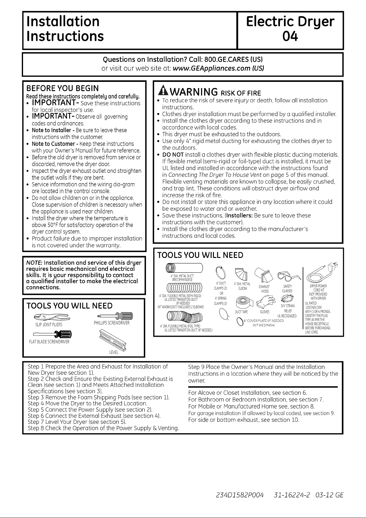
TOOLS YOU WILL NEED
SLIPJOINTPLIERS
FLATBLADESCREWDRIVER
PHILLIPSSCREWDRIVER
%
04
WARNING RISK OF FIRE
• Toreduce the riskof severe injury or death, follow all installation
instructions.
• Clothes dryer installation must be performed by a qualified installer.
• Install the clothes dryer according to these instructions and in
accordance with local codes.
• This dryer must be exhausted to the outdoors.
• Use only 4" rigid metal ducting for exhausting the clothes dryer to
the outdoors.
• DO NOT install a clothes dryer with flexible plastic ducting materials.
If flexible metal (semi-rigid or foil-type) duct is installed, it must be
ULlisted and installed in accordance with the instructions found
in Connecting TheDryer ToHouse Venton page 5 of this manual.
Flexible venting materials are known to collapse, be easily crushed,
and trap lint. These conditions will obstruct dryer airflow and
increase the risk of fire.
• Do not install or store this appliance in any location where it could
be exposed to water and or weather.
• Savethese instructions. (Installers: Besure to leave these
instructions with the customer).
• Install the clothes dryer according to the manufacturer's
instructions and local codes.
TOOLS YOU WILL NEED
)
41DIAMETALDUCT V/ll
(RECOMMENDED)
41DIAFLEXIBLEMETAL(SEMDRIGID)
ULLISTEDTRANSITIONDUCT
(IFNEEDED)
KFWXBBXlOB77)INCLUDES2ELBOWS)
4'DIAFLEXIBLEMETAL(FOILTYPE)
ULLISTEDTRANSITIONDUCT(IFNEEDED)
# DUCT # DIA _v_ETAL
CLAMPS(2) ELBOW
CLAMPS(2)
#SPRING
",,../..jj
EXHAUST
OR
DUCTTAPE
HOOD
GLOVES
SAFETY
GLASSES
]/#'STRAIN
RELIEF
ULRECOGNIZED
DRYERPOWER
CORDKIT
(NOTPROVIDED
WITHDRYER)
ULRATED
1BO/24OV]OA
WITH3OR4 PRONGS
IDENTIFYTHEPLUG
TYPEASPERTHE
HOUSERECEPTACLE
BEFOREPURCHASING
LINECORD
Step 1 Prepare the Area and Exhaust for Installation of
New Dryer (seesection 1).
Step 2 Check and Ensurethe Existing External Exhaust is
Clean (see section 1) and Meets Attached Installation
Specifications (see section 3).
Step 3 Remove the Foam Shipping Pads(see section 1).
Step 4 Move the Dryer to the Desired Location.
Step 5 Connect the Power Supply (see section 2).
Step 6 Connect the External Exhaust (seesection 4).
Step 7 LevelYour Dryer (seesection 5).
Step 8 Check the Operation of the Power Supply & Venting.
Step 9 Place the Owner's Manual and the Installation
Instructions in a location where they will be noticed by the
owner.
For Alcove or Closet Installation, see section 6.
For Bathroom or Bedroom Installation, see section 7.
For Mobile or Manufactured Home see, section 8.
For garage installation (if allowed by local codes), see section 9.
For side or bottom exhaust, see section 10.
234D1582PO04 31-16224-2 03-12 GE
Page 2
Installation Instructions
Minimum Clearance Other Than Alcove or Closet Installation
Minimum clearance to combustible surfaces and for air opening are: 0 in. clearance both sides and ] in. rear.
Consideration must be given to provide adequate clearance for installation and service.
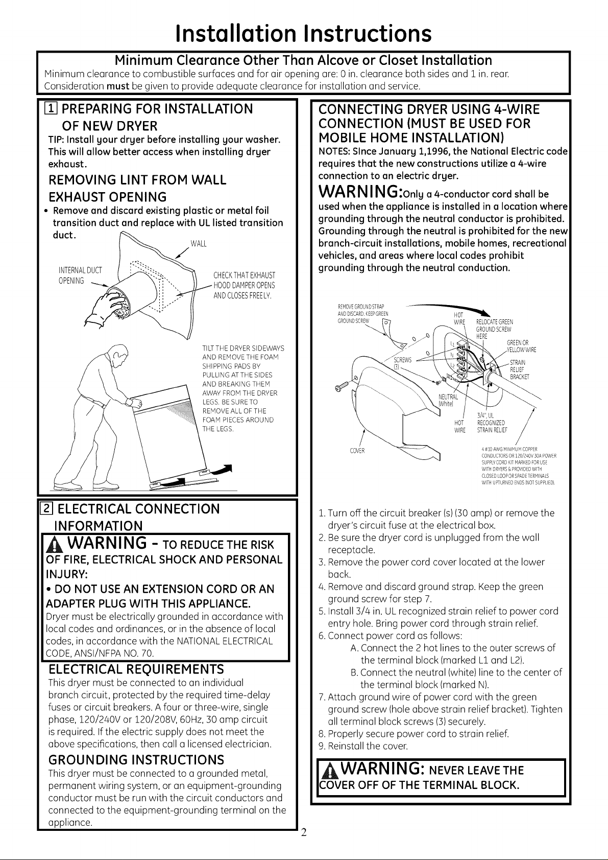
m PREPARING FOR INSTALLATION
OF NEW DRYER
TIP:Install your dryer before installing your washer.
This will allow better accesswhen installing dryer
exhaust.
REMOVING LINT FROM WALL
EXHAUST OPENING
• Remove and discard existing plastic or metal foil
transition duct and replace with UL listed transition
duct.
WALL
/
INTERNALDUCT
OPENING i- HOODDAHPEROPENS
CHECKTHATEXHAUST
ANDCLOSESFREEL?.
TILTTHE DRYERSIDEWAYS
AND REMOVETHE FOAM
SHIPPING PADS BY
PULLING ATTHE SIDES
AND BREAKINGTHEM
AWAY FROM THE DRYER
LEGS. BE SURE TO
REMOVEALL OF THE
FOAM PIECESAROUND
THE LEGS.
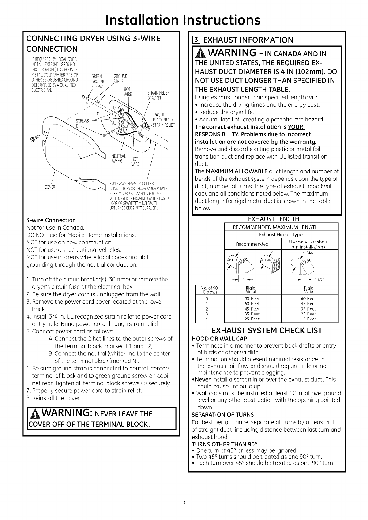
CONNECTING DRYER USING 4-WIRE
CONNECTION (MUST BE USED FOR
MOBILE HOME INSTALLATION)
NOTES:Since Jonuarg 1,1996, the National Electric code
requires that the new constructions utilize a 4-wire
connection to an electric dryer.
WARNING:onlua4-conductor cord shall be
used when the appliance is installed in a location where
grounding through the neutral conductor is prohibited.
Grounding through the neutral is prohibited for the new
branch-circuit installations, mobile homes, recreational
vehicles, and areas where local codes prohibit
grounding through the neutral conduction.
REHOVEGROUNDSTRAP
ANDDISCARDKEEPGREEN
GROUNDSCREW_" 7 WIRE RELOCATEGREEN
"4. _ HERE GREENOR
COVER
GROUNDSCREW
HOT
RECOGNIZED
STRAINRELIEF
WIRE
3/4",UL
4#10 AWGHINIHUH COPPER
CONDUCTORSOR120/240V 50APOWER
SUPPLYCORDKITHARKEDFORUSE
WITHDRYERS& PROVIDEDWITH
CLOSEDLOOPORSPADETERMINALS
WiTH UPTURNEDENDS(NOTSUPPLIED)
RELIEF
BRACKET
Izl ELECTRICAL CONNECTION
INFORMATION
WARNING - TOREDUCETHERISK
OF FIRE, ELECTRICAL SHOCK AND PERSONAL
INJURY:
• DO NOT USE AN EXTENSION CORD OR AN
ADAPTER PLUG WITH THIS APPLIANCE.
Dryer must be electrically grounded in accordance with
local codes and ordinances, or in the absence of local
codes, in accordance with the NATIONALELECTRICAL
CODE,ANSI/NFPANO.70.
ELECTRICAL REQUIREMENTS
This dryer must be connected to an individual
branch circuit, protected by the required time-delay
fuses or circuit breakers. A four or three-wire, single
phase, 120/240V or 120/208V, 60Hz, 30 amp circuit
is required. If the electric supply does not meet the
above specifications, then call a licensed electrician.
GROUNDING INSTRUCTIONS
This dryer must be connected to a grounded metal,
permanent wiring system, or an equipment-grounding
conductor must be run with the circuit conductors and
connected to the equipment-grounding terminal on the
appliance.
1.Turn off the circuit breaker (s)(30 amp) or remove the
dryer's circuit fuse at the electrical box.
2.Be sure the dryer cord is unplugged from the wall
receptacle.
3.Remove the power cord cover located at the lower
back.
4.Remove and discard ground strap. Keep the green
ground screw for step 7.
5.Install 3/4 in. ULrecognized strain relief to power cord
entry hole. Bring power cord through strain relief.
6.Connect power cord as follows:
A.Connect the 2 hot lines to the outer screws of
the terminal block (marked L1and L2).
B.Connect the neutral (white) line to the center of
the terminal block (marked N).
7.Attach ground wire of power cord with the green
ground screw (hole above strain relief bracket). Tighten
all terminal block screws (3)securely.
8.Properly secure power cord to strain relief.
9.Reinstall the cover.
WARNING: NEVER LEAVE THE
COVER OFF OF THE TERMINAL BLOCK.
2
I
Page 3
Installation Instructions
CONNECTING DRYER USING 3-WIRE
CONNECTION
iFREQUIRED,BYLOCALCODE,
INSTALLEXTERNALGROUND
(NOTPROVIDED)TOGROUNDED
METALCOLDWATERPiPEOR GREEN GROUND
OTHERESTABLISHEDGROUND GROUND STRAP
DETERMINEDBYAOUALIFIED SCREW
ELECTRICIAN. HOT
q)
COVER
WIRE
NEUTRAL
(White) HOT
] #10 AWGMiNiMUMCOPPER
CONDUCTORSOR120/240V]0APOWER
SUPPLYCORDKITMARKEDFORUSE
WITHDRYERS&PROVIDEDWITHCLOSED
LOOPORSPADETERMINALSWITH
UPTURNEDENDS(NOTSUPPLIED).
STRAINRELIEF
BRACKET
WiRE
3/#',UL
RECOGNIZED
EXHAUST INFORMATION
WARNING -IN CANADAANDIN
THE UNITED STATES, THE REQUIRED EX-
HAUST DUCT DIAMETER IS 4 IN (102ram). DO
NOT USE DUCT LONGER THAN SPECIFIED IN
THE EXHAUST LENGTH TABLE.
Using exhaust longer than specified length will:
• Increase the drying times and the energy cost.
• Reducethe dryer life.
• Accumulate lint, creating a potential fire hazard.
The correct exhaust installation is YOUR
RESPONSIBILITY.Problems due to incorrect
installation are not covered by the warranty.
Remove and discard existing plastic or metal foil
transition duct and replace with ULlisted transition
duct.
The MAXIMUM ALLOWABLEduct length and number of
bends of the exhaust system depends upon the type of
duct, number of turns, the type of exhaust hood (wall
cap), and all conditions noted below. The maximum
duct length for rigid metal duct is shown in the table
below.
3-wire Connection
Not for use in Canada.
DONOTuse for Mobile Home Installations.
NOTfor use on new construction.
NOTfor use on recreational vehicles.
NOTfor use in areas where local codes prohibit
grounding through the neutral conduction.
1.Turn off the circuit breaker(s) (30 amp) or remove the
dryer's circuit fuse at the electrical box.
2.Be sure the dryer cord is unplugged from the wall.
3. Remove the power cord cover located at the lower
back.
4. Install 3/4 in. ULrecognized strain relief to power cord
entry hole. Bring power cord through strain relief.
5.Connect power cord as follows:
A. Connect the 2 hot lines to the outer screws of
the terminal block (marked L1and L2).
B.Connect the neutral (white) line to the center
of the terminal block (marked N).
6.Be sure ground strap isconnected to neutral (center)
terminal of block and to green ground screw on cabi-
net rear.Tighten all terminal block screws (3)securely.
7.Properly secure power cord to strain relief.
8. Reinstall the cover.
I WARNING: NEVER LEAVE THE
COVER OFF OF THE TERMINAL BLOCK.
EXHAUST LENGTH
RECOMMENDED MAXIMUM LENGTH
Exhaust Hood Types
Recommended Use only for short
run installations
4"I-- "-I I_21/2"
No.of 90° Rigid Rigid
Elbows Metal Metal
0 90 Feet 60 Feet
I 60 Feet 45 Feet
2 45 Feet 35 Feet
3 35 Feet 25 Feet
4 25 Feet 15 Feet
EXHAUST SYSTEM CHECK LIST
HOOD ORWALL CAP
• Terminate in a manner to prevent back drafts or entry
of birds or other wildlife.
• Termination should present minimal resistance to
the exhaust air flow and should require little or no
maintenance to prevent clogging.
•Never install a screen in or over the exhaust duct. This
could cause lint build up.
• Wall caps must be installed at least 12 in. above ground
level or any other obstruction with the opening pointed
down.
SEPARATIONOF TURNS
Forbest performance, separate allturns by at least 4 ft.
I
of straight duct, including distance between last turn and
exhaust hood.
TURNSOTHERTHAN 90°
• One turn of 45oor less may be ignored.
• Two 450turns should be treated as one 900turn.
• Eachturn over 450 should be treated as one 900turn.
4" DIA.
3
Page 4

Installation Instructions
EXHAUST INFORMATION (cont)
SEALING OFJOINTS
• Alljoints should be tight to avoid leaks. The male end of
each section of duct must point away from the dryer.
• Do not assemble the ductwork with fasteners that
extend into the duct. Theywill serve as a collection
point for lint.
• Duct joints can be made air and moisture-tight by
wrapping the overlapped joints with duct tape.
• Horizontal runs should slope down toward the outdoors
1/4 inch per foot
INSULATION
Duct work that runs through an unheated area or is
near air conditioning should be insulated to reduce
condensation and lint build-up.
I--4-1EXHAUST CONNECTION
, WARNING - TO REDUCE THE
RISK OF FIRE OR PERSONAL INJURY:
• This clothes dryer must be exhausted to the outdoors.
• Useonly 4" rigid metal ducting for the home exhaust
duct.
• Useonly 4" rigid metal or UL-listed flexible metal
(semi-rigid or foil-type) duct to connect the dryer
to the home exhaust duct. It must be installed
in accordance with the instructions found in
"Connecting The Dryer To House Vent" on page 5 of
this manual.
• Donot terminate exhaust in a chimney, a wall,
a ceiling, gas vent, crawl space, attic, under an
enclosed floor, or in any other concealed space
of a building. The accumulated lint could create a
potential fire hazard.
• Neverterminate the exhaust into a common duct
with a kitchen exhaust system. A combination of
grease and lint creates a potential fire hazard.
• Donot use duct longer than specified inthe exhaust
length table. Longer ducts can accumulate lint,
creating a potential fire hazard.
• Never install a screen inor over the exhaust duct. This
will cause lint to accumulate, creating a potential fire
hazard.
• Donot assemble ductwork with any fasteners
that extend into the duct. Thesefasteners can
accumulate lint, creating a potential fire hazard.
• Donot obstruct incoming or exhausted air.
• Provide an access for inspection and cleaning of
the exhaust system, especially at turns and joints.
Exhaust system shall beinspected and cleaned at
least once a year.
THIS DRYER COMES READY FOR REAR
EXHAUSTING. IF SPACE IS LIMITED, USE
THE INSTRUCTIONS IN SECTION 10 TO
EXHAUST DIRECTLY FROM THE SIDES OR
BOTTOM OF THE CABINET.
STANDARD REAR EXHAUST
(Vented at floor level)
FOR STRAIGHT LINE INSTALLATION,
CONNECT THE DRYER EXHAUST TO
THE EXTERNAL EXHAUST HOOD
USING DUCT TAPE OR CLAMR
EXTERNAL
DUCT
OPENING
DUCT TAPE OR
DUCT CLAMP
4" METAL DUCT
(CUT TO PROPER
LENGTH) DUCT TAPE OR
DUCT CLAMP
NOTE: WE STRONGLY RECOMMEND SOLID METAL EXHAUST DUCTING.
HOWEVER, IF FLEXIBLE DUCTING IS USED IT MUST BE UL-LISTED METAL
NOT PLASTIC.
STANDARDREAREXHAUST
(Vented above floor level)
ELBOWHIGHLY
_ RECOMMENDED
RECOMMENDED
CONFiGURATiON
TOMINiMiZE
EXHAUST
BLOCKAGE.
ELBOWHIGHLY
RECOMMENDED-
NOTE: ELBOWS WILL PREVENT DUCT
KINKING AND COLLAPSING.
[] LEVELINGAND STABILIZING YOURDRYER
4LEVELNGLEGS
4
Page 5
Installation Instructions
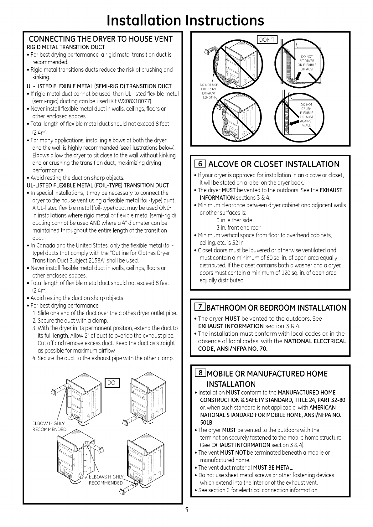
CONNECTING THE DRYERTO HOUSEVENT
RIGIDMETALTRANSITIONDUCT
• Forbest dryingperformance,arigidmetaltransition duct is
recommended.
• Rigidmetaltransitionsducts reducethe riskof crushingand
kinking.
UL-LISTEDFLEXIBLEMETAL(SEMI-RIGID)TRANSITIONDUCT
• Ifrigidmetalductcannotbeused,then UL-listedflexible metal
(semi-rigid)ducting can beused(KitWX08XZ0077).
• Neverinstallflexiblemetalductinwalls,ceilings,floorsor
otherenclosedspaces.
•Totallengthofflexiblemetal duct shouldnot exceed8feet
(2.4m).
• Formany applications,installingelbowsat boththe dryer
andthe wall ishighly recommended(seeillustrationsbelow).
Elbowsallow the dryer to sit closeto thewall without kinking
andor crushingthetransition duct,maximizingdrying
performance.
•Avoidrestingtheductonsharpobjects.
UL-LISTEDFLEXIBLEMETAL[FOIL-TYPE)TRANSITIONDUCT
• inspecialinstallations,it may be necessaryto connectthe
dryerto the houseventusinga flexiblemetal (foil-type)duct.
A UL-listedflexiblemetal (foil-type)duct may be usedONLY
in installationswhererigid metalor flexiblemetal (semi-rigid)
ductingcannot be usedANDwhere a4"diametercan be
maintainedthroughout theentire lengthof thetransition
duct.
• inCanadaandthe UnitedStates,onlythe flexiblemetal (foil-
type)ductsthat complywith the"Outlinefor ClothesDryer
TransitionDuct Subject2158A"shallbe used.
• Neverinstallflexiblemetalductinwalls,ceilings,floorsor
otherenclosedspaces.
•Totallengthofflexiblemetal duct shouldnot exceed8feet
(2.4m).
•Avoidrestingtheductonsharpobjects.
• Forbest dryingperformance:
1.Slideoneend of the duct over theclothes dryeroutlet pipe.
2.Securetheduct with a clamp.
3.With the dryerin its permanentposition,extendthe duct to
its fulllength.Allow 2"of duct to overlapthe exhaustpipe.
Cutoff and removeexcessduct. Keepthe duct as straight
aspossiblefor maximumairflow.
4.Securetheduct to the exhaustpipewith theother clamp.
CRUSH
FLEXIBLE
EXHAUST
AGAINST
EXHAUST _)LENGT_ DO NOT
ALCOVE OR CLOSET INSTALLATION
•Ifyour dryeris approvedfor installationin an alcoveor closet,
itwill bestatedon a labelon the dryerback.
•ThedryerMUSTbeventedto the outdoors.Seethe EXHAUST
INFORMATIONsections3 &4.
• Minimumclearancebetweendryercabinetandadjacentwalls
or other surfacesis:
0 in.either side
3 in.front and rear
• Minimumverticalspacefromfloorto overheadcabinets,
ceiling,etc.is 52in.
• Closetdoorsmust be Iouveredor otherwiseventilated and
mustcontaina minimum of60 sq.in.of openareaequally
distributed.If thecloset containsboth a washerand a dryer,
doorsmust contain a minimumof 120sq.in.ofopen area
equallydistributed.
(-7-1BATHROOMOR BEDROOM INSTALLATION
• The dryer MUST be vented to the outdoors. See
EXHAUSTINFORMATIONsection 3 &4.
• The instollation must conform with local codes or, inthe
absence of local codes, with the NATIONAL ELECTRICAL
CODE,ANSI/NFPA NO.70.
ELBOW HIGHLY
RECOMMENDED
L__S HIGHLY
RECOMMENDED
(8-1MOBILE ORMANUFACTURED HOME
INSTALLATION
• installationMUSTconform to the MANUFACTUREDHOME
CONSTRUCTION&SAFETYSTANDARD,TITLE24,PART32-80
or,when suchstandard isnot applicable,with AMERICAN
NATIONALSTANDARDFORMOBILEHOME,ANSI/NFPANO.
5018.
• ThedryerMUSTbeventedto the outdoorswith the
termination securelyfastenedto the mobilehomestructure.
(SeeEXHAUSTINFORMATIONsection 3& 4).
• Thevent MUSTNOTbe terminatedbeneatha mobileor
manufactured home.
• Thevent duct material MUSTBEMETAL.
• Donot usesheet metalscrewsorother fasteningdevices
which extendintothe interiorof theexhaustvent.
• Seesection 2for electrical connectioninformation.
5
Page 6

Installation Instructions
BY LOCAL CODES)
ryers installed in garages must be elevated 18 inches
t ARAGE INSTALLATION (IF ALLOWED
6cm) above the floor.
1161DRYEREXHAUST TO RIGHT, LEFT
OR BOTTOM CABINET
WARNING - BEFOREPERFORMING
THIS EXHAUST INSTALLATION, BE SURE
TO DISCONNECT THE DRYER FROM ITS
ELECTRICAL SUPPLY. PROTECT YOUR HANDS
AND ARMS FROM SHARP EDGES WHEN
WORKING INSIDE THE CABINET. BE SURE TO
WEAR GLOVES
REMOVE
SCREW
ANDSAVE.
ADDING NEW DUCT
FIXING
HOLE
PORTION"A"
RIGHTOR
LEFTSIDE
EXHAUST
Reconnectthe cut portion(A)ofthe duct to the blower
housing.Makesurethat the shortenedduct isalignedwith
the tab inthe base.Usethe screwsaved previouslyto secure
the duct in place through the tab on the appliancebase.
ADDING ELBOW AND DUCT FOR
EXHAUST TO LEFT OR RIGHT SIDE OF
CABINET
• Preassemble 4" elbow with 4" duct. Wrap duct tape
around joint.
• Insert duct assembly, elbow first, through the side
opening and connect the elbow to the dryer internal
duct.
REMOVE,_
DESIRED
KNOCKOUT
lONEONLY).
Detach and remove the bottom, right or left side knockout
as desired. Remove the screw inside the drger exhaust duct
and save. Pull the duct out of the drger.
Note: Only 4" round rigid metal ducting allowed inside
drger.
B A
FIXINGHOLE
9"
Cut the duct as shown and keep portion A.
TAB LOCATION
BENDTAB
UP45o
CAUTION: Be sure not to pullor dQmoge the
electrical wires inside the dryer when inserting the
duct.
EXHAUSTCAN
BEADDEDTO
LEFTORRIGHTSIDE
\
DUCT
TAPE
Through the rear opening, locate the tab inthe middle of
the appliance base. Liftthe tab to about 450 using a flat
blade screwdriver.
6
Page 7

Installation Instructions
• Apply duct tape as shown on the joint between the
dryer internal duct and the elbow.
DUCT
CAUTION:
Internal duct joints must be
secured with tope, otherwise
theg meg separate and cause
a safetg hazard.
ADDING ELBOW FOR EXHAUST
THROUGH BOTTOM OF CABINET
• Insert the elbow through the rear opening and connect
it to the dryer internal duct.
• Apply duct tape on the joint between the dryer internal
duct and elbow, as shown on page 6.
J
CAUTION:
Internal duct joints must be secured with tape,
otherwise they may separate and cause a
safety hazard.
ADDING COVER PLATE TO REAR
I-_ CHANGING DIRECTION OF
DOOR OPENING
1.Open the door and remove the filler plugs opposite the
hinges. With the door completely open, remove the
bottom screws from each hinge on the dryer face. In-
sert these screws about half way into the TOP holes, for
each hinge on the opposite side (where you removed
the filler plugs).Apply firm pressure to get the screw
started.
2.Loosen the top screws from each hinge on the dryer
face half way. With one hand holding the top of the
door and the other hand holding the bottom, remove
the door from the dryer by lifting it UPand OUT.
3. Rotate the door 180°. Insert the door on the opposite
side of the opening by moving the door IN and DOWN
until the top hinge and the bottom hinge are resting on
the top screws inserted in step 1.
4. Remove the remaining screws from the side of the
opening from which the door was removed. With these
screws secure each hinge at the bottom. Tighten the
two top screws on each hinge. Reinsert the plastic
plugs on the side from which the door was removed.
REMOVE THE
BOTTOM SCREW LOOSEN THE TOP SCREWS
FROM EACH HINGE FROM EACH HINGE ON
ON THE DRYER FACE THE DRYER FACE
HALF WAY
OF CABINET (SIDES AND BOTTOM
EXHAUST)
PLATE
(KITWEliVi454)
Connect standard metal elbows and ducts to complete
the exhaust system. Cover back opening with a plate (Kit
WEIIV]454)available from your local service provider.
Placedryer in final location.
WARNING-NEVER LEAVE THE BACK
OPENING WITHOUT THE PLATE. (Kit
WEIM454)
MOVE THE DOORIN AND
DOWN UNTIL THE TOP HINGE SECURE EACH HINGE
AND THE BOTTOM HINGES ARE AT THE BOTTOM AND
RESTING ON THE TOP SREWS TIGHTEN THE TWO TOP
INSERTED IN STEP 1 SCREWS OF EACH HINGE
7
Page 8

Installation Instructions
I_1 CONNECTING INLET HOSES
(on some models)
To produce steam, the dryer must connect to the cold
water supply. Since the washer must also connect to the
cold water, a "Y"connector isinserted to allow both inlet
hoses to make that connection at the same time.
NOTE: Usethe new inlet hoses provided; never
use old hoses.
1.Turn the cold water faucet off. Remove the washer inlet
hose from the washer fill valve connector (cold).
2. Ensure the rubber fiat washer is in place and screw the
female coupling of the short hose onto the washer fill
valve connector. Tighten by hand until firmly seated.
3. Attach the female end of the "Y"connector to the
male coupling of the short hose. Ensure the rubber fiat
washer is in place. Tighten by hand until firmly seated.
4. Insert the filter screen in the coupling of the washer's
inlet hose. If a rubber flat washer is already in place
remove it before installing the filter screen. Attach this
coupling to one male end of the "Y" connector. Tighten
by hand until firmly seated.
5. Ensurethe rubber fiat washer isin place and attach the
dryer's long inlet hose to the other male end of the "Y"
connector. Tighten by hand until firmly seated.
6. Ensurethe rubber fiat washer isin place and attach
the other end of the dryer's long inlet hose to the fill
valve connector at the bottom of the dryer back panel.
Tighten by hand until firmly seated.
I_1 CONNECTING INLET HOSES (cont.)
7. Using pliers, tighten all the couplings with an additional
two-thirds turn.
NOTE:Do not overtighten. Damage to the couplings may
result.
8. Turn the water faucet on.
9. Check for leaks around the "Y" connector, faucet and
hose couplings.
WATER SUPPLY REQUIREMENTS
Hot and cold water faucets HUST be installed within 42
in.(107 cm) of your washer's water inlet. Thefaucets
HUSTbe :3/4 in. (1.9cm) garden hose-type so inlet hoses
can be connected. Water pressure HUSTbe between 10
and 120 pounds per square inch. Your water department
can advise you of your water pressure.
NOTE:A water softener is recommended to reduce
buildup of scale inside the steam generator if the home
water supply is very hard.
I-_ SERVICING
WARNING - LABELALLWIRES
PRIOR TO DISCONNECTING WHEN
SERVICING CONTROLS. WIRING
ERRORS CAN CAUSE IMPROPER AND
DANGEROUS OPERATION AFTER
SERVICING/INSTALLATION.
Forservicing phone numbers for replacement parts, and
other information, refer to Owner's Honual or visit our
Web site.
REGISTERYOUR NEW APPLIANCE TO RECEIVEANY
IMPORTANT PRODUCT NOTIFICATIONS.
Please go to www.GEAppliances.com or mail in your
Product Registration Card.
For questions on installation, coil: 800.626.2000 (US)or
800-561-3:344 (Canada).
8
 Loading...