

Page 1
installation
uilt-
instructions
BEFORE YOU BEGIN
Read these instructions completely and
carefully.
I RTANT = Observe a,,
governing codes and ordinances.
, Note to Installer- Be sure to leave these instructions
for the consumer's and local inspector's use.
, Note to Consumer- Keep these instructions with your
Owner's Manual for future reference.
, Skill Level - installation of this dishwasher requires
basic mechanical, electrical and plumbing skills.
Proper installation isthe responsibility of the
installer. Product failure due to improper installation
is not covered under the GEAppliance Warranty.
See warranty information.
, Completion Time - 1 to 3 Hours. New installations
require more time than replacement installations.
is was
er
I PORTANT - Thedishwasher
MUST be installed to allow for future removal from the
enclosure ifservice is required.
If you received a damaged dishwasher, you should
immediately contact your dealer or builder.
Optional Accessories - See the Owner's Manual for
available custom panel kits.
FOR YOUR SAFETY
Read and observe all CAUTIONS and WARNINGS
shown throughout these instructions. While performing
installations described in this booklet, gloves, safety
glasses or goggles should be worn.
READ CAREFULLY.
KEEP THESE iNSTRUCTiONS.
PDW8100 Series
PDW8200 Series
PDW8400 Series
PDW8500 Series
PDW8600 Series
PDW8700 Series
PDW8800 Series
*For PDW9700 Series also refer to the Instructions
provided on the template packed with that model.
PDW9200 Series
PDW9700 Series*
PDW9800 Series
Page 2
Installation Preparation
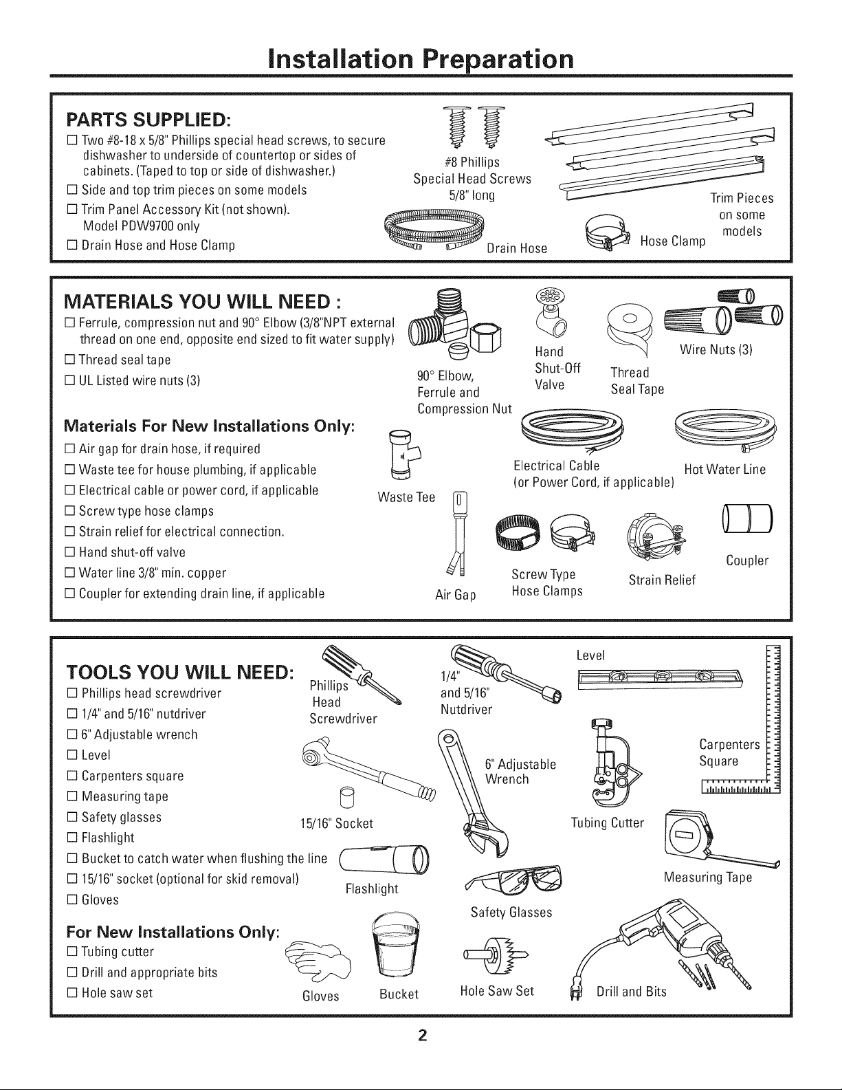
PARTS SUPPLIED:
[] Two#8-18x 5/8"Phillipsspecial head screws, to secure
dishwasher to underside of countertop or sides of
cabinets. (Tapedto top or side of dishwasher.}
[] Side and top trim pieces on some models
[] Trim PanelAccessory Kit(not shown}.
Model PDW9700only
[] Drain HoseandHose Clamp
_Drain Hose
MATERIALS YOU WiLL NEED :
[] Ferrule, compression nut and 90°Elbow (3/8"NPTexternal
thread on one end, opposite end sizedto fit water supply}
[] Thread sealtape
[] ULListed wire nuts (3}
Materials For New Installations Only:
[] Air gap for drain hose,if required '[,4-_.
[] Waste tee for house plumbing,if applicable
[] Electrical cable or power cord, if applicable Waste Tee
[] Screwtype hose clamps
[] Strain relief for electrical connection.
[] Handshut-off valve
[] Water line 3/8"min.copper
[] Couplerfor extending drain line, if applicable Air Gap
#8 Phillips
Special HeadScrews
5/8"long
90° Elbow, Thread
Ferrule and SealTape
Compression Nut
Trim Pieces
on some
HoseClamp
Hand
Shut-Off
Valve
Electrical Cable HotWater Line
(or Power Cord,if applicable}
Screw Type Strain Relief
Hose Clamps
Wire Nuts (3)
models
Coupler
TOOLS YOU WiLL NEED:
[] Phillipshead screwdriver
[] 1/4"and 5/16"nutdriver
[] 6"Adjustable wrench
[] Level
[] Carpenters square
[] Measuring tape
[] Safety glasses
[] Flashlight
[] Bucketto catch water when flushing the line
[] 15/16"socket (optional for skid removal}
[] Gloves
For New Installations Only:
[] Tubingcutter
[] Drill and appropriate bits
[] Holesaw set
Phillips
Head
Screwdriver
15/16"Socket _VVre%nch
Gloves Bucket HoleSaw Set
Level
and 5/16"
Nutdriver
Carpenters
Square
Tubing Cutter
Measuring Tape
Flashlight
Safety Glasses
Drill and Bits
2
Page 3
Installation Preparation
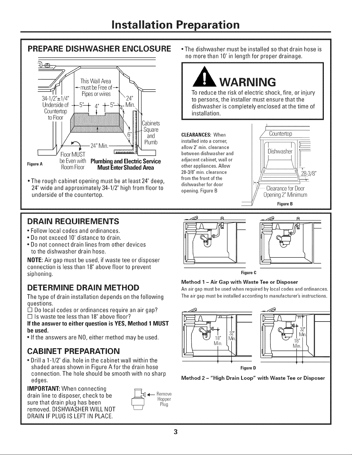
PREPARE DISHWASHER ENCLOSURE ,The dishwasher must be installed so that drain hose is
no more than 10' in length for proper drainage.
Free
34-1/2"_+1/4"
Undersideof
Countertop
toFloor
Square
and
Plumb
FloorMUST
FigureA
=The rough cabinet opening must be at least 24" deep,
24"wide and approximately 34-1/2" high from floor to
underside of the countertop.
beEvenwith
RoomFloor
PlumbingandElectric Service
Must Enter Shaded Area
DRAIN REQUIREMENTS
, Follow local codes and ordinances.
, Do not exceed 10' distance to drain.
, Do not connect drain lines from other devices
to the dishwasher drain hose.
NOTE: Air gap must be used, if waste tee or disposer
connection is less than 18" above floor to prevent
siphoning.
DETERMINE DRAIN METHOD
The type of drain installation depends on the following
questions.
[] Do local codes or ordinances require an air gap?
[] Is waste tee less than 18" above floor?
If the answer to either question is YES, Method I MUST
be used.
,If the answers are NO, either method may be used.
CABINET PREPARATION
, Drill a 1-1/2" dia. hole inthe cabinet wa!l within the
shaded areas shown in Figure Aforthe drain hose
connection. The hole should be smooth with no sharp
edges.
iMPORTANT: When connecting
WARNING
To reduce the risk of electric shock, fire, or injury
to persons, the installer must ensure that the
dishwasher is completely enclosed atthe time of
installation.
CLEARANCES:When
installed into a corner,
allow 2"min. clearance
between dishwasher and
adjacent cabinet, wall or
other appliances. Allow
28-3/8"min. clearance
from the front of the
dishwasher for door
opening. Figure B
FigureC
Method 1 - Air Gap with Waste Tee or Disposer
An air gap must be used when required by local codes and ordinances.
The air gap must be installed according to manufacturer's instructions.
32"
Min. 18"
FigureD
Method 2 - "High Drain Loop" with Waste Tee or Disposer
Countertop
ClearanceforDoor
Opening2"Minimum
FigureB
_ ...-___ re
_-l----ir=_
In.I
1
drain line to disposer, check to be _ 4-- Remove
sure that drain plug has been Plug
removed. DISHWASHER WILL NOT
DRAIN IF PLUG IS LEFTIN PLACE.
Hopper
3
Page 4
Installation Preparation
PREPARE ELECTRICAL WIRING
FORPERSONAL SAFETY:Remove
house fuse or open circuit breaker
before beginning installation. Do not
use an extension cord or adapter plug
with this appliance.
Electrical Requirements
.This appliance must be supplied with 120V,60 Hz., and
connected to an individual properly grounded branch
circuit, protected by a 15 or 20 ampere circuit breaker
or time delay fuse.
.Wiring must be 2wire with ground and rated for 75°C
(176°F).
. If the electrical supply does not meet the above
requirements, call a licensed electrician before
proceeding.
Grounding Instructions-Cable Direct
This appliance must be connected to a grounded metal,
permanent wiring system, or an equipment grounding
conductor must be run with the circuit conductors and
be connected to the equipment grounding terminal or
lead on the appliance.
Grounding Instructions-Power Cord Models
This appliance must be grounded, in the event of a
malfunction or breakdown, grounding will reduce the
risk of electric shock by providing a path of least resis-
tance for electric current. This appliance is equipped
with a cord having an equipment grounding conductor
and a grounding plug. The plug must be plugged into an
appropriate outlet that is installed and grounded in
accordance with all local codes and ordinances.
The improper connection of the equip-
ment grounding conductor can result in
a risk of electric shock. Check with a
qualified electrician or service repre-
sentative if you are in doubt that the
appliance is properly grounded.
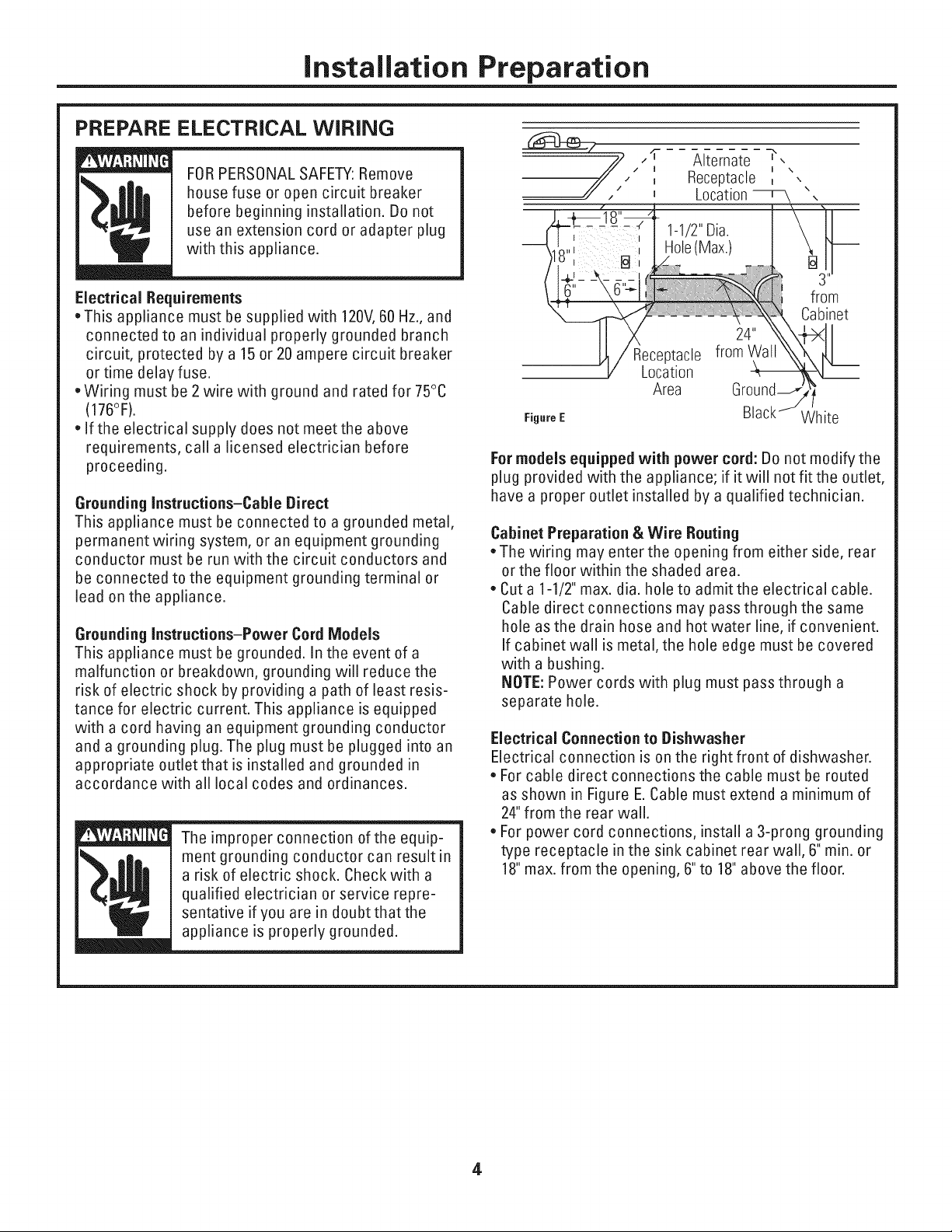
Alternate _',
Receptacle _ \
Location
1-1/2"Dia.
Hole(Max.)
Receptacle
Location
Area
Figure E White
Formodels equipped with power cord: Do not modify the
plug provided with the appliance; if it will not fit the outlet,
have a proper outlet installed by a qualified technician.
Cabinet Preparation & Wire Routing
*The wiring may enter the opening from either side, rear
or the floor within the shaded area.
. Cut a 1-1/2" max. dia. hole to admit the electrical cable.
Cable direct connections may pass through the same
hole as the drain hose and hot water line, if convenient.
If cabinet wal! is metal, the hole edge must be covered
with a bushing.
NOTE: Power cords with plug must pass through a
separate hole.
Electrical Connection to Dishwasher
Electrical connection is on the right front of dishwasher.
. For cable direct connections the cable must be routed
as shown in Figure E.Cable must extend a minimum of
24"from the rear wall.
. For power cord connections, install a 3-prong grounding
type receptacle in the sink cabinet rear wall, 6" min. or
18"max. from the opening, 6"to 18" above the floor.
I \
from
Cabinet
4
Page 5

Installation instructions
PREPARE HOT WATER LiNE
.The line may enter from either side, rear or floor
within the shaded area shown in Figure E
.The line may pass through the same hole as the
electrical cable and drain hose. Or,cut an additional
1-1/2" dia. hole to accommodate the water line. If
power cord with plug is used, water line must not
pass through power cord hole.
I
I
I \
I \
I \
fl i
Shut-off 1-1/2" Dia.
Valve
ii
ii
n
Hot,j:=:::
ii
"2"-
From
Cabinet
Cabinet Face-_
FigureF
Water Line Connection
. Turn off the water supply.
. Install a hand shut-off valve in an accessible location,
such as under the sink. (Optional, but strongly recom-
mended and may be required by local codes.)
. Water connection is on the left side of the dishwasher.
Install the hot water inlet line, using no less than 3/8"
O.D.copper tubing. Route the line as shown in Figure F
and extend forward at least 19"from rear wall.
. Adjust water heater for 120°Fto 150°F temperature.
. Flush water line to clean out debris.
.The hot water supply line pressure must be 20-120 PSI.
STEP 1 CHECK DOOR BALANCE
.With dishwasher on the wood skid, check the door
balance by opening and closing the door.
. If the door drops when released, increase the spring
tension. If the door rises when released, decrease the
tension.
. Position the spring for increased or decreased tension
as required.
. Model families have different spring mounting holes
and tension adjustment methods. Refer to the appro-
priate figure for your model.
PDW8100-PDW8800 Series
Figure G
PDW9200-PDW9800 Series
CAUTION:
Do not remove wood base until you are
readyto install the dishwasher. The dishwasher will tip
over when the door is opened if the wood base is
removed.
BEFORE YOU BEGIN
Locate and set aside (for use in Step 12)the
2 Phillips special head screws wrapped with yellow
tape and stuck to the top or side of the dishwasher.
Remove drain hose from upper rack, if it has not been
pre-installed, and set aside for use in Step 7.
Pulley_
Decrease
{
Shoulder
CorrectSpring
Figure H CableRouting
TiP: If door does not open easily or falls too quickly,
check the spring cable routing. Check that the cable is
properly aligned on the pulley. See Figure H.
5
Increas6
Tension
Tension
Page 6

Installation instructions
[STEP 2] REMOVE WOOD BASE,
iNSTALL LEVELING LEGS
I PORTANT= oo.o,.,o.o.
wood base! Damage will occur.
=Move the dishwasher close to the installation
location and lay it on its back.
=Remove the four leveling legs on the underside of
the wood base with an adjustable
wrench or 15/16"socket.
* Discard base.
Figure J
=Screw leveling legs back intothe dishwasher
frame, approximately 1/4"from frame as shown.
[STEP 3] REMOVE TOEKICK
=Remove the 2toekick screws and toekick. Set aside
for use in Step 18.
[STEP 4] INSTALL POWER CORD
Skip this step if dishwasher will be direct wired or
has a factory installed power cord.
Use Power Cord Kit WX09X70910, available for
purchase from an authorized GEAppliance Dealer.
The power cord and connections must comply with
the National Electrical Code, Section 422 and/or local
codes and ordinances.
, Maximum power cord length is 6'.
A B
Remove Insert Power
Junction Box CordWires Thru\
Cover Strain Relief
and Tighteun_d¢_Gro '
C CheckThat White, Black and----1_'
Green Dishwasher Wires Are Threaded
ThruSmall Hole in Bracket
FigureL
, Connect incoming power cord white
(or ribbed) to dishwasher white, black (or smooth) to
black and ground to dishwasher green wire. Use UL
listed wire nuts of appropriate size.
, Replace junction box cover. Be sure wires are not
pinched under the cover.
D
Use UL Listed
Wire Nuts
Figure K
Remove2
ToekickScrews
STEP 5 iNSTALL 90° ELBOW
* Wrap 90° elbow with
thread seal tape.
*Install a 90° elbow
onto the
water valve.
go°
Elbow
FigureM
* Do not over tighten the 90° elbow, water valve
bracket could bend or water valve fitting could break.
, Position the end of the elbow to face the rear of the
dishwasher.
6
Frontof Dishwasher
Fill
Hose
Thread
Seal Tape
Valve
Bracket
Page 7

Installation instructions
STEP 6 POSiTiON WATER LiNE
AND HOUSE WiRiNG
. Position water supply line and house wiring on the
floor of the
opening to avoid
interference with
base of dish-
washer and
components
under dishwasher.
FigureN
m
. 4'' -
'House\\
__ W terW,r,n 'S
STEP 7 iNSTALL DRAIN HOSE,
GUIDE THROUGH CABINET
Skip this step if drain hose has been pre-installed. In
this step you will need the drain hose set aside prior
to Step 1.
. Stand the dishwasher upright.
. Remove the clamp attached DrainOutlet ShoulderStop
to the drain hose. De
careful not to damage
the drain hose.
=Slip the supplied
hose clamp over the
big end ofthe hose.
Figure0
*Push hose over the drain outlet on the back side of
the dishwasher. See Figure O. Push the hose over
the outlet and against the shoulder stop.
*Tighten the hose clamp with a 1/4" nut driver.
Insulation
Blanket Wate_
STEP 8 SLIDE DISHWASHER
PARTIALLY INTO CABINET
D0 NOT PUSHAGAINST FRONTPANELWiTH KNEES.
DAMAGE WiLL OCCUR.
* Slide dishwasher into the opening a few inches at
a time.
DoNot PushAgainst
Front Door PanelWith
Knee.Damageto The
Door PanelWill Occur.
, As you proceed, pull the drain hose through the open-
ing under the sink. Stop pushing when the dishwasher
is a few inches forward of adjacent cabinets.
, Make sure drain hose is not kinked under the dish-
washer and there is no interference with the water
line and wiring or any other component.
FigureQ
STEP 9 INSTALL TRIM PIECES
Skip this step if trim is not supplied with the
dishwasher.
,' Locate trim strips inside dishwasher.
, Press trim onto the tub flange on each side. Start with
the top edge, pressing on as you move towards the
bottom.
, Press the two top trim pieces on each side of the latch.
, Open and close the door to check that trim does not
bind and does not interfere with door latch.
Trim Strip
Hose
Hou_se
Wiring
Figure P Power Cord
(if Used)
. Position the dishwasher infront of the opening.
insert drain hose intothe cabinet side. if power cord
is used, guide the end through a separate hole.
Trim-
Strip
FigureR
Page 8

Installation instructions
STEP 10 POSiTiON DISHWASHER UNDER COUNTERTOP
=Push the dishwasher intothe cabinet.
=Push the sides with your hands. Do not use your knee
against the door since door damage will occur.
=Check that the tub insulation blanket does not get
"bunched-up" or interfere with the springs as you
slide it into the cabinet.
=Center the dishwasher inthe opening.
=Checkthat the edges of the dishwasher door are
behind the cabinet frame and aligned with the front
face of the cabinet as shown.
=Carefully open and close the door to ensure that the
door panel does not catch or rub on the cabinet
frame.
=If the door catches or rubs on the frame, reposition
and/or level the unit (see Step 11) until the door
moves freely and does not contact the cabinet frame.
Positioning for
PDW9200-PDW9800 Series
The controls on these models are designed to be
hidden by your countertop. Align the dishwasher as
shown in Figure W. Leave a 1/2" minimum gap between
the underside of the countertop and the top of the
dishwasher door as shown in Figure W.
NOTE: For flush installations of the PDW9700 Series
models, cut offthe back panel of the tub insulation
blanket so that the dishwasher door panel can be
aligned with the kitchen cabinet panels.
Do Not PushAgainst_
Knee.Damageto The
Door PanelWill Occur.
FigureS
Door
Fitsand
Swings
Back
Behind
Cabinet,
Frame
Correct
Alignment
FigureT
RepositionDishwasher
/ , \ byGraspingBoth
/i
....... Alignment_
With Hands
\\\\\\\
\,
DoorCatches.........
3nCabinetFrame,
/
/'
NOTE: If the drain hose gets "bunched-up" behind the
unit it can prevent the controls from being hidden by
the countertop.
NOTE: If this dishwasher is replacing an existing dish-
washer, the old countertop bracket screw holes may
not be in the correct position to accept a top-control
model. New holes may be required.
TiP: The leveling legs can be used to increase or
decrease the amount of gap between the controls and
the countertop affecting the visibility of the controls.
PORTANT = o°vo
minimum gap between the controls and the underside
of the countertop to prevent condensation and damage
to the control panel from screwheads.
J
ControlsHidde_
by Countertop
FigureU
Countertop
i ;io2r"cMia_aGncae'eP
Figure V FigureW
8
Page 9

Installation Instructions
STEP 11 LEVEL DISHWASHER
IMPORTANT - Dishwashermustbe
level for proper dish rack operation and wash
performance.
* ForPDW9200-PDW9800 Series: Make sure 1/2"
minimum gap is
maintained (see
Figure W).
, Place level on
door to check that
the dishwasher is
level side-to-side.
Place level on
rack track inside
tub to check
that the dish-
washer is level
front-to-back.
/ \
Check l
Level.-
Front .......... . Check
to Back _eel
Side
// _;:::3Z_13",
FigureX
If the dishwasher is J. Box
not level, level it by ----...
adjusting the four
leveling legs
individually.
If adjustment to the
right rear leveling
leg is required, access ....,,\Turn Leg
it by loosening junction _o Adjust /
box bracket screw (through " ..............
the access hole) and rotate bracket clockwise.
TiP: Pull lower rack out, about halfway. Check to
be sure the rack does not roll forward or back into
dishwasher, if the rack rolls in either direction, the
dishwasher must be leveled again.
* If door hits the tub, the dishwasher is not installed
correctly. Adjust leveling legs to align door to tub.
Access Hole
Figure Y
IMPORTANT - Afterleveling,verifythat
the dishwasher is still in the correct position shown in
Step 10.
STEP 12 SECURE DISHWASHER, TO COUNTERTOP OR CABINET
in this step you wiil need
the 2 Phillips special head
screws set aside prior to
Step 1.
The dishwasher must be
secured to the
countertop or the
cabinet sides.
When countertops
are made of wood,
use Method 1.When
countertops are granite
or other materials that will not accept screws, use
Method 2 to secure dishwasher atthe sides.
SideMount!no
Brackets
Figure Z
IMPORTANT - Drive screws straight and
flush. Protruding screw heads will scratch the top or sides
of the control panel and can interfere with door closing.
Method1
Secure dishwasher
towood
countertop
=Fasten the
dishwasher to the
underside of the
countertop with the
2 Phillips special head screws provided.
Brackets Wood Countertop
Figure AA
Method 2
Secure dishwasherwith side-mountingbrackets
. Remove plug buttons (one on each side),
. Install screws through the dishwasher and into the
adjacent cabinet on each side, Reinstall plug buttons,
Granite Countertop Side-Mounting Brackets
__Plug B_ttons _
Figure BB
EitherMethod
Countertop
/
/
1/2"___
Min.I Dishwasher Door
FigureCC
ForPDW9200-PDW9800Series:When step iscomplete, close
dishwasher door and verifythat gap between countertop and
top of dishwasher door is at least 1/2".
9
Page 10

Installation Instructions
STEP 13]CONNECT WATER SUPPLY
- CompressionNut ....---
Ferrule._
Connect water supply line to 90° elbow.
, Slide compression nut, then ferrule over end of
water line.
, Insert water line into 90° elbow.
_\x
Hot Water
__ 90° Ebow SupplyLiney /
, Slide ferrule against elbow and secure with
compression nut.
IMPORTANT - Checktobesurethatdoor
spring does not rub or contact the fill hose or water
supply line. Test by opening and closing the door. Re-route
the lines if a rubbing noise or interference occurs.
[STEP 14] CONNECT DRAIN LiNE DRAIN LiNE iNSTALLATiON
FOLLOW ALL LOCAL CODES AND ORDINANCES.
Identify the type of drain hose you have. The molded
end of the drain hose will fit 5/8" through 1"diameter
inlet ports of the air gap, waste tee or disposer.
, Determine size of inlet port.
, Cut drain hose connector on the marked line, if
required, to fitthe inlet port.
TypeI _ Cutting Line
FigureDD
/ 90° Elbow
DoorSpring
, Connect drain line to air gap, waste tee or disposer
using either previously determined method.
Method 1 - Air gap with waste tee or disposer
/
Type 2
Cutting Lines
IMPORTANT:Donot cut corrugated
portion of hose
iMPORTANT:Donot cut corrugated
FigureEE
portion of hose
,If a longer drain hose is required, add up to 42" of length
for a total of 10' to the factory installed hose. Use 5/8" or
7/8" inside diameter hose and a coupler to connect the
two hose ends. Secure the connection with hose
clamps.
FigureFF
Coupler
Hose Clamp
HoseClamp
,Securethe drain hose to the air gap, waste tee or
disposer with clamps.
NOTE: TOTAL DRAIN HOSE LENGTH MUST NOT EXCEED
10' FORPROPERDRAIN OPERATION.
Waste Tee Instaihtion Disposer Instaihtion
Method 2 - "High drain loop" with waste tee or disposer
Fasten to underside
_ _ of countertep,
FigureGG
Fasten to underside
_ f_ ofcountertop
32" I
Waste Tee Instalhtion
Figure HH
When connecting drain line to dis-
IMPORTANT -
poser, check to be sure that drain plug
Disposer Instaihtion
Remove
Hopper
Plug
has been removed. DISHWASHER
WILL NOT DRAIN IF PLUG IS LEFTIN PLACE.
TiP: Avoid unnecessary service call charges. Always be
sure disposer drain plug has been removed before
attaching dishwasher drain hose to the disposer.
10
Page 11

Installation instructions
STEP 15 CONNECT POWER
SUPPLY
Skip this step if equipped with power cord.
Proceed to step 16.
Verify that power is turned off at the source.
, Remove junction box cover "A".
=Secure house wiring to the back of the junction box
with a strain relief "B".
, Locate the three dishwasher wires, (white, black and
green) with stripped ends. Insert dishwasher wires
through the small hole in the junction box "C'. Use
wire nuts to connect incoming ground to green,
white to white and black to black "D".
, Replace junction box cover "A'. Check to be sure
that wires are not pinched under the cover.
A
Remove
Junction Box
Cover
C CheckThatWhite. Blackand
GreenDishwasherWiresAreThreaded
ThruSmallHolein Bracket
E ReplaceJunction Box Cover
FigureJJ
If house wiring is not 2-wire with
ground, a ground must be provided by
the installer. When house wiring is
aluminum, be sure to use UL Listed
anti-oxidant compound and aluminum-
to-copper connectors
S
InsertPower:,, _,_,_ _- )
C°sr_ra_'rt_s,_hrL_. ` __
andTighten I _ i
Ground _ __Black
, ite
UseULListed
WireNuts
J
D
STEP 16 PRETEST CHECK LIST
Review this list after installing your dishwasher to
avoid charges for a service call that is not covered
by yourwarranty.
[] Checkto be sure power is OFE
[] Open door and remove all foam and paper
packaging.
[] Locate the Owner's Manual in the literature
package.
[] Read the Owner's Manual for operating
instructions.
[]
Check door opening and closing. If door does not
open and close freely, check for proper routing of
spring cable over pulley. See Step 1, Figure G and
H. If door drops or closes when released, adjust
spring tension.
[]
Check to be sure that wiring is secure under the
dishwasher, not pinched or in contact with door
springs or other components. See Steps 8 and 10.
[]
Check door alignment with tub. If door hits tub,
level dishwasher. See Step 11.
[]
Pull lower rack out, about halfway. Check to be
sure it does not roll back or forward onthe door.
If the rack moves, adjust leveling legs. See Step 11.
[]
Check door alignment with cabinet. If door hits
cabinet, reposition or relevel dishwasher. See
Steps 10, 11 and 12.
[]
Check that door spring does not contact water
line, fil! hose, wiring or other components. See
Step 13.
[]
Verify water supply and drain lines are not kinked
or in contact with other components. Contact with
motor or dishwasher frame could cause noise. See
Steps 6 and 8.
[]
Turn on the sink hot water faucet and verify water
temperature. Incoming water temperature must
be between 120°Fand 150°E Aminimum of 120°F
temperature is required for best wash perfor-
mance. See "Prepare Hot Water Line," page 5.
[]
Add 2 quarts of water to the bottom of the
dishwasher to lubricate the pump seal.
[]
Turn on water supply. Check for leaks. Tighten
connections if needed.
11
[]
Remove protective film if present from the control
panel and door.
Page 12

Installation instructions
STEP 17 DISHWASHER WET TEST
[] Turn on power supply (or plug power cord into
outlet, if equipped}.
[] Start the unit to check for leaks.
PDW8100-PDW8800 Series:
- Latch door
-Push RINSE ONLY pad
- Push START/RESETpad
PDW9200-PDW9800 Series:
-Push RINSE ONLY pad
- Push START/RESETpad
-Close door
[] Check to be sure that water enters the dishwasher.
If water does not enter the dishwasher, check to be
sure that water and power are turned on.
[] Check for leaks under the dishwasher. If a leak is
found, turn off power supply, then tighten connec-
tions. Restore power after leak is corrected.
[] Check for leaks around the door. A leak around the
door could be caused by door rubbing or hitting
against adjacent cabinets. Reposition the dish-
washer if necessary. See Step 10.
[] The dishwasher will drain and turn off about 5
minutes after it was started. Check drain lines. If
leaks are found, turn power off atthe breaker and
correct plumbing as necessary. Restore power
after corrections are made. See Steps 7and 14.
[STEP 181 REPLACE TOEKICK
=Place toekick against the legs of the dishwasher.
Figure KK
, Align the toekick with the bottom edge and make sure
it is against the floor.
, Insert and tighten the two toekick attachment screws.
The toekick should stay in contact with the floor.
TiP: Make sure toekick is against floor to minimize
noise.
[] Open dishwasher door and make sure most of the
water has drained. If not, check that disposer plug
has been removed and/or air gap is not plugged.
See Step 14.Also check drain line for kinking.
[] Runthe dishwasher through another "Rinse Only"
cycle. Check for leaks and correct if required.
SPECIFICATIONSSUBJECTTOCHANGEWITHOUTNOTICE
[STEP 19] LITERATURE
, Be sure to leave complete literature package and
installation instructions with the consumer.
IPub.No.31-30585 ]
Dwg.No.206C1559P125
ND. 923-40 (11/04)
 Loading...