

GE GDWF160RSS, CDWT980RSS, GLD4456RCS, GDWT100R, GDWT160RSS Installation Instructions Manual
...Page 1
GE Consumer & Industrial
Appliances
Installation Instructions
Built-In Dishwasher
If you have questions, call 800.GE.CARES (800.432.2737) or visit our Website at: GEAppliances.com
In Canada call 1.800.561.3344 or www.GEAppliances.ca
STOP
Read these instructions completely and
carefully.
IMPORTANT – Observe all governing codes and
ordinances.
• Note to Installer – Be sure to leave these instructions for the
consumer’s and local inspector’s use.
• Note to Consumer – Keep these instructions with your
Owner’s Manual for future reference.
• Skill Level – Installation of this dishwasher requires
basic mechanical, electrical and plumbing skills. Proper
installation is the responsibility of the installer. Product
failure due to improper installation is not covered under
the GE Appliance Warranty. See warranty information.
• Completion Time – 1 to 3 Hours. New installations require
more time than replacement installations.
READ CAREFULLY.
KEEP THESE INSTRUCTIONS.
S
L
O
R
T
N
O
C
K
C
O
L
Y
O
R
T
D
D
E
T
A
E
H
S
S
E
R
P
S
D
N
O
C
N
E
S
A
3
R
E
O
L
F
C
HEATED
D
E
IZ
T
I
DRY
N
A
S
PRE
BEFORE YOU BEGIN
ENHANCEMENTS
G
IN
Y
R
D
G
N
WASH
I
S
IN
R
ADDED
G
2 4 8
IN
H
S
A
W
HEAT
G
IN
S
DELAY
SELECTIONS
N
E
S
HOURS
START
ANTI
RESET
COOK
BACTERIA
NORMAL
WARE
SPEED
WASH
CHINA
CYCLE
RINSE
CRYSTAL
ONLY
Stainless Steel Tub Models
IMPORTANT – The dishwasher MUST
be installed to allow for future removal from the enclosure
if service is required.
If you received a damaged dishwasher, you should
immediately contact your dealer or builder.
Optional Accessories – See the Owner’s Manual for available
custom panel kits.
FOR YOUR SAFETY
Read and observe all CAUTIONS and WARNINGS
shown throughout these instructions. While performing
installations described in this booklet, gloves and either
safety glasses or goggles should be worn.
imagination at work
Page 2
■
■
■
■
■
■
■
■
Installation Preparation
■
■
■
■
■
■
■
■
■
■
■
■
■
■
■
■
■
■
■
■
■
■
■
■
■
■
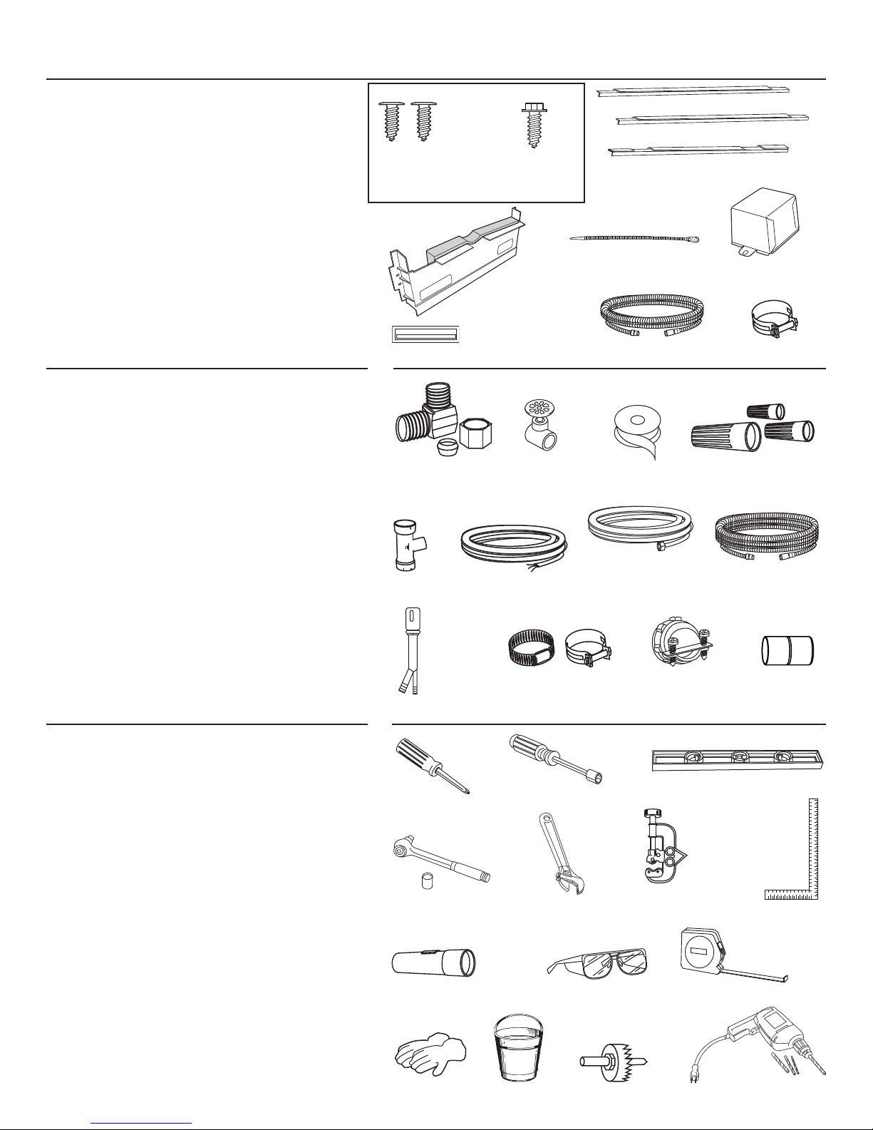
PARTS SUPPLIED WITH
INSTALLATION KIT:
■ Two #8-18 x 5/8" Phillips special head screws, to
secure dishwasher to underside of countertop or
sides of cabinets.
■ Junction box cover and #10-1/2" hex-head screw
■ Side and top trim
■ Trim Panel Accessory Kit (not shown)
(Custom panel models only)
■ Sound upgrade kit (some models)
■ Drain hose (78") , drain hose hanger and hose
clamp
■ Literature, product samples and/or coupons
■ Hard water test strip (Models with Bulk Dispenser)
MATERIALS YOU WILL NEED:
■ Ferrule, compression nut and 90° Elbow (3/8" NPT
external thread on one end, opposite end sized to
fit water supply)
■ Thread seal tape
■ UL-listed wire nuts (3)
Screw Kit
#8 Phillips
Special Head Screws
5/8” long
Sound Upgrade Kit
(Some Models)
Hard Water Test Strip
(Models with
Bulk Dispenser)
90° Elbow,
Ferrule and
Compression Nut
#10 Hex-Head
J-Box Screw
1/2" long
Hand
Shut-Off
Valve
Trim Pieces
Drain Hose Hanger
Drain Hose (78")
Thread
Seal Tape
Side Trim
Side Trim
Top Trim
Junction
Box Cover
Hose Clamp
Wire Nuts (3)
Materials For New Installations Only:
■ Air gap for drain hose, if required
■ Waste tee for house plumbing, if applicable
■ Electrical cable or power cord, if applicable
■ Screw-type hose clamps
■ Strain relief for electrical connection
■ Hand shut-off valve
■ Water line 3/8" min. copper
■ Coupler for extending drain line, if applicable
■ GPF10L 10' drain hose, if needed
TOOLS YOU WILL NEED:
■ Phillips-head screwdriver
■ 1/4" and 5/16" nutdriver
■ 6" Adjustable wrench
■ Level
■ Carpenter’s square
■ Measuring tape
■ Safety glasses
■ Flashlight
■ Bucket to catch water when flushing the line
■ 15/16" socket
■ Gloves
For New Installations Only:
■ Tubing cutter
■ Drill and appropriate bits
■ Hole saw set
2
Waste Tee
Air
Gap
PhillipsHead
Screwdriver
1/4" and
15/16" Socket
Gloves
Hot Water Line
Electrical Cable
(or Power Cord, if applicable)
Screw-Type
Hose Clamps
1/4" and
5/16" Nutdriver
6" Adjustable
Wrench
Safety GlassesFlashlight
Bucket Hole Saw Set Drill and Bits
Strain Relief
Level
Tubing Cutter
GPF10L
10' Drain Hose
Coupler
Carpenter’s
Square
Measuring Tape
Page 3
Installation Preparation–Enclosure
PREPARE DISHWASHER ENCLOSURE
WARNING
ADVERTENCIA
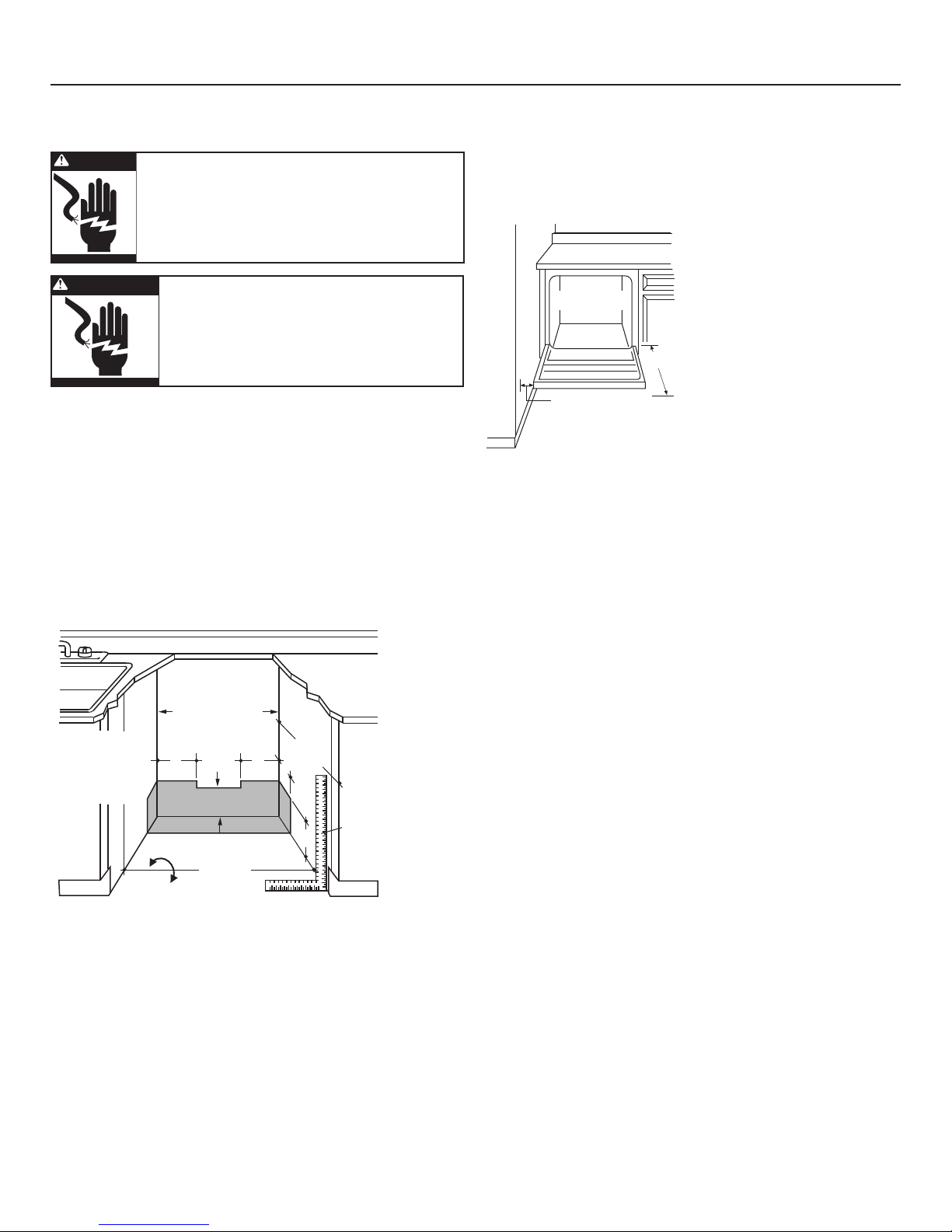
• The rough cabinet opening must have a minimum width
and depth of 24" and height of 34-1/2" ± 1/4" from the fl oor
to the underside of the countertop.
• The back wall should be free of pipes or wires.
• Adjacent cabinets should be square and plumb to ensure
a good fi t. Refer to Figure A
• For a corner installation, allow 2" minimum clearance
between the dishwasher and the adjacent wall.
• Provide at least 28-3/8" in front of the dishwasher to allow
the dishwasher door to open fully. Refer to Figure B
To reduce the risk of shock, fire, or injury
to persons, the installer must ensure that
the dishwasher is completely enclosed at
the time of installation.
Para reducir el riesgo de choque, incendio
o lesión a personas, el instalador se
debe cerciorar de que la lavadora esté
completamente cerrada en el momento
de la instalación.
• The dishwasher must be installed no more than 10 feet
from sink for proper drainage.
• The dishwasher must be fully enclosed on the top, sides
and back.
• The dishwasher must not support any part of the enclosure.
Clearances:
Countertop
Dishwasher
28-3/8" Minimum
2" Minimum
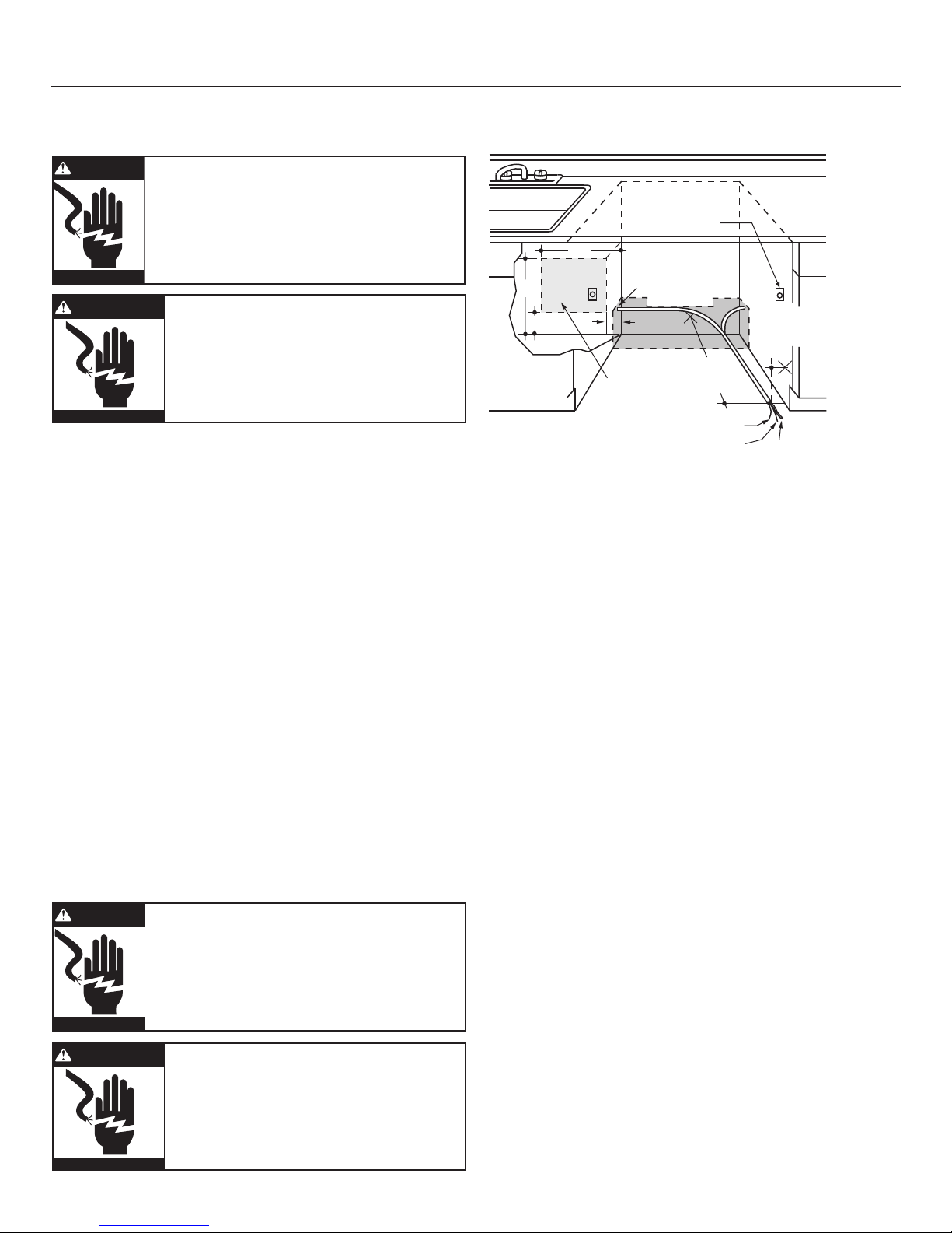
Figure B
In a corner installation, provide at
least 2" clearance between the
dishwasher and the adjacent
cabinet, wall, or other appliance.
Provide at least 28-3/8" of clearance
in front of the dishwasher.
This Wall Area
Must Be Free of
Pipes or Wires
34-1/2" ± 1/4"
Underside of
Countertop
5" 5"
4"
4"
24"
Min.
to Floor
Cabinets
Square
6"
24" Min.
and
Plumb
Floor MUST
be Even with
Room Floor
Figure A
• Make sure the fl oor is level inside the opening and even with
the fi nished fl oor of the kitchen. This will facilitate removal
of the dishwasher at a later date for service, if needed.
Special consideration for a dishwasher installed on
a elevated platform
The elevated platform must be flat and level.
Plumbing and Electric Service
Must Enter Shaded Area
3
Page 4
32"
Min.
18"
Min.
32"
Min.
18"
Min.
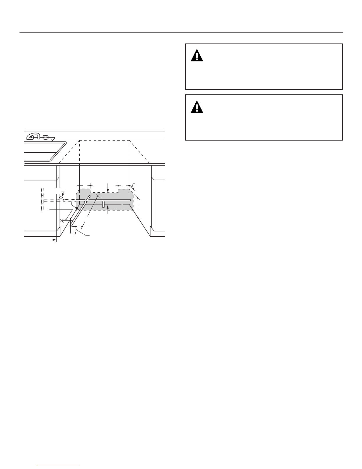
Installation Preparation–Drain
PREPARE DRAIN PLUMBING
Drain Requirements
• Drain hose must not exceed 10 feet in length.
• A high drain loop or air gap is required. See below.
Drain Method
The type of drain installation depends on the following:
• Do local codes or ordinances require an air gap?
• Is waste tee less than 18" above the fl oor?
If the answer to either question is yes, an air gap must be used.
Refer to Method 1 (Figure C) in the adjacent illustrations.
If both answers are no, either an air gap or high drain loop may
be used. Refer to Method 1 (Figure C) or Method 2 (Figure D)
in the adjacent illustrations
NOTE: Drain hose elevation must not exceed 48".
Special consideration for a dishwasher installed on
a elevated platform
lf the dishwasher is installed on an elevated platform, a high
drain loop of at least 32" above the platform must be provided
in addition to the air gap or drain loop requirement determined
above. This is necessary for proper drain performance.
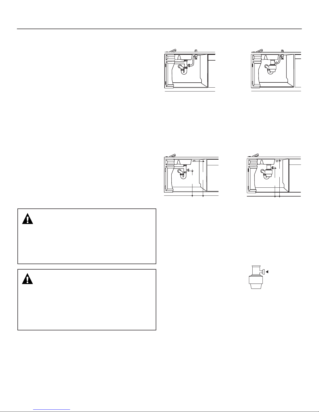
METHOD 1–Air Gap with Waste Tee or Disposer
Figure C
Waste Tee Installation
Disposer Installation
METHOD 2–High Drain Loop with Waste Tee
or Disposer
Use the drain hose hanger included in the installation kit to
attach the drain hose to the underside of the countertop.
Attachment will be made in a later step.
Figure D
Waste Tee Installation
Disposer Installation
CAUTION
An air gap MUST BE USED if the drain hose is connected to
waste tee or disposer lower than 18" above the floor level.
Failure to provide the proper drain connection height with
an air gap or 32" minimum, high drain loop will result in
improper draining of the dishwasher, which may cause
damage.
PRECAUCIÓN
SE DEBE USAR un espacio de aire si la manguera
de drenaje se conecta a la T de desechos o al triturador
menos de 18" por encima del nivel del piso. No disponer
la altura correcta de la conexión del drenaje con
un espacio de aire o 32" de mínimo, una curva alta
de drenaje resultará en un drenaje incorrecto
de la lavadora, lo que pude causar daños.
Install waste tee or disposer and the air gap according to the
manufacturer’s instructions.
Cabinet Preparation for drain line
Drill a 1-1/2" diameter hole in the cabinet wall within the
shaded area shown in Figure A for the drain hose. Make
sure there are no sharp edges. The drain hose will be passed
through this hole and connected to the drain in a later step.
IMPORTANT – When
connecting the drain line to a
disposer, check to be sure that
drain plug has been removed.
Dishwasher will not drain if
plug is left in place.
Remove
Drain
Plug
4
Page 5
Installation Preparation–Electrical Supply
PREPARE ELECTRICAL WIRING
WARNING
ADVERTENCIA
Electrical Requirements
• This appliance must be supplied with 120V, 60Hz., and
connected to an individual properly grounded branch circuit
protected by a 15- or 20-ampere circuit breaker or timedelay fuse.
• Wiring must be 2 wire with ground and rated for 75°C (176°F).
• If the electrical supply does not meet the above
requirements, call a licensed electrician before proceeding.
Grounding Instructions–Permanent Connection
This appliance must be connected to a grounded-metal,
permanent wiring system, or an equipment-grounding
conductor must be run with the circuit conductors and be
connected to the equipment-grounding terminal or lead on
the appliance.
Grounding Instructions–Power Cord Models
This appliance must be grounded. In the event of a malfunction
or breakdown, grounding will reduce the risk of electric shock
by providing a path of least resistance for electric current.
This appliance is equipped with a cord having an equipmentgrounding conductor and a grounding plug. The plug must
be plugged into an appropriate outlet that is installed and
grounded in accordance with all local codes and ordinances.
WARNING
FOR PERSONAL SAFETY: Remove house fuse
or open circuit breaker before beginning
installation. Do not use an extension cord or
adapter plug with this appliance.
PARA SEGURIDAD PERSONAL: Retire el
fusible de la casa o abra el interruptor de
circuitos antes de empezar la instalación.
No use un cable de extensión o enchufe
adaptador con este aparato.
The improper connection of the equipment
grounding conductor can result in a risk
of electric shock. Check with a qualified
electrician or service representative if you
are in doubt that the appliance is properly
grounded.
0[cTa]PcT
ATRT_cPR[T
;^RPcX^]
'
%
'
%
!3XP
7^[T<Pg
"Ua^\
2PQX]Tc
!#
ATRT_cPR[T
Ua^\FP[[
;^RPcX^]
0aTP
Figure E
For models equipped with power cord: Do not modify the plug
provided with the appliance; if it will not fit the outlet, have a
proper outlet installed by a qualified technician.
Cabinet Preparation and Wire Routing
• The wiring may enter the opening from either side, rear
or the fl oor within the shaded area dimensioned in Figure A
and illustrated above.
• Cut a 1-1/2" max. diameter hole to admit the electrical cable.
Cable direct connections may pass through the same hole
as the drain hose and hot water line, if convenient. If cabinet
wall is metal, the hole edge must be covered with a bushing.
Note: Power cords with plug must pass through a separate
hole.
Electrical Connection to Dishwasher
Electrical connection is on the right front of dishwasher.
• For cable direct connections the cable must be routed as
shown in Figure E. Cable must extend a minimum of 24"
from the rear wall.
• For power cord connections, install a 3-prong grounding
type receptacle in the adjacent cabinet rear wall, 6" min.
or 18" max. from the opening, 6" to 18" above the fl oor.
The receptacle must be accessible and therefore cannot
be installed in the back wall of the dishwasher enclosure.
6a^d]S
1[PRZ
FWXcT
ADVERTENCIA
La conexión incorrecta del conductor de
conexión a tierra del equipo puede resultar
en choque eléctrico. Consulte con un
electricista calificado o representante
de servicio si tiene dudas de la conexión
a tierra del aparato.
5
Page 6
Installation Preparation–Hot Water Supply
6"
5"
5"
4"
Cabinet Face
Shut-off
Valve
4"
2" From Floor
19" From Wall
2"
From
Cabinet
1-1/2" Dia.
Hole
Hot
PREPARE HOT WATER SUPPLY
Hot Water Line
• The line may enter from either side, rear or floor within the
shaded area shown in Figure F.
• The line may pass through the same hole as the electrical
cable and drain hose, or an additional 1-1/2" diameter hole
may be cut to accommodate the water line. If a power cord
with plug is used, the water line must not pass through the
power cord hole.
CAUTION
The hot water supply line pressure must be at least 20 PSI.
Lower pressures could cause the water valve to leak and
cause water damage.
PRECAUCIÓN
La línea de presión del suministro de agua caliente debe
ser al menos 20 PSI. Presiones inferiores podrían causar
que la válvula del agua gotee y causar daños por agua.
Figure F
Water Line Connection
• Turn off the water supply.
• Install a hand shut-off valve in an accessible location, such
as under the sink. (Optional, but strongly recommended
and may be required by local codes.)
• The water connection is on the bottom-left side of the
dishwasher. Install the hot water inlet line, using 3/8"
or larger copper tubing. Route the line as shown in Figure F
and extend forward at least 19" from rear wall.
• Adjust the water heater to deliver water between 120°F
and 150°F.
• Flush water line to clean out debris. Use a bucket to catch
water and debris.
• The hot water supply line pressure must be between 20
and 120 PSI.
6
Page 7
Dishwasher Installation
CAUTION
Do not remove the wood base until you are ready to
install the dishwasher. The dishwasher will tip over
when the door is opened if the base is removed.
PRECAUCIÓN
No retire la base de madera hasta que esté listo para
instalar la lavadora de platos. Cuando la puerta se abra,
la lavadora de platos se inclinará si la base se retira.
STEP 1 – LOCATE INSTALLATION ITEMS
• Locate the items in the installation package and set aside for
use in the listed steps.
• Trim pieces – Step 2
• Junction box cover – Step 7 or Step 18
• Drain hose and clamp – Step 10
• Screw Kit – Step 15
• Drain hose hanger – Step 17
• Owner’s Manual – Step 19 and Step 24
• Hard Water test strip – Step 21
• Sound upgrade kit (selected models) – Step 22
• Product samples and/or coupons – Step 24
STEP 2 – INSTALL TRIM PIECES
In this step, you will need the trim pieces set aside in Step 1.
• Press top trim piece onto top of tub fl ange. Start with the
right edge and work your way to the left.
• Repeat process with the left and right trim pieces working
from the top down.
• Open and close the door to check that trim does not bind
and does not interfere with door latch or door hinges.
Trim Strip
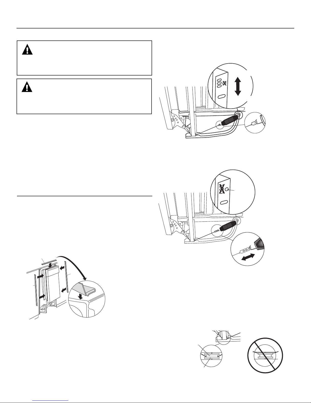
Type 1 – One-hole cable
Adjust tension by moving spring hook to one of the three holes
on the tub leg.
8=2A40B4
342A40B4
Figure H
>]T7^[T
Type 2 – Three-hole cable
Adjust tension by moving spring hook to one of the three holes
on the pulley cable.
Use This
Mounting
Hole
Decrease
Tension
Trim
Strip
Trim
Strip
Figure G
STEP 3 – CHECK DOOR BALANCE
• With dishwasher on the wood skid, check the door balance
by opening and closing the door.
• If the door drops when released, increase the spring tension.
If the door rises when released, decrease the tension.
• There are two types of counterbalance and therefore two
methods of adjustment. Identify which counterbalance is
present and adjust tension accordingly. Please note: If there
are 3 holes on the cable, use the cable to adjust; if there is
one hole on cable, use the tub leg to adjust.
Increase
Figure I
After adjusting spring tension, open and close the door to
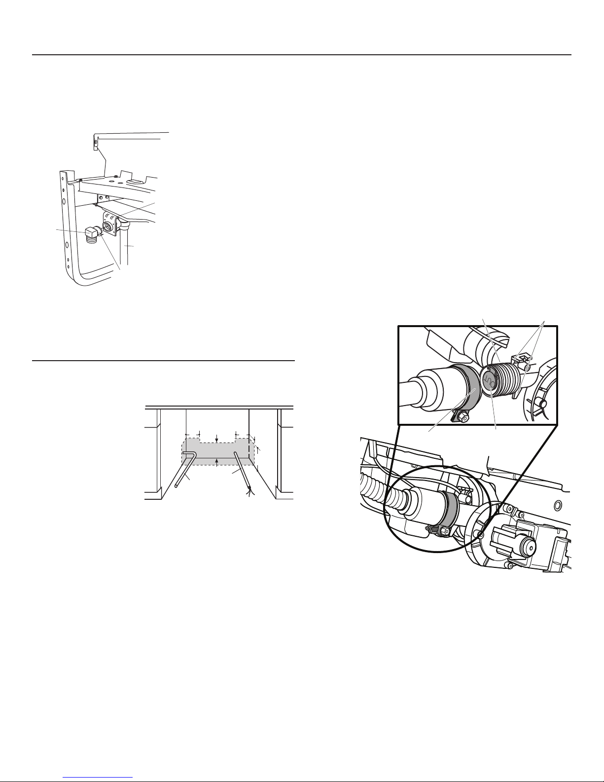
make sure the door operates smoothly. If the door is hard
to move or if the spring cable binds, check the routing of
the spring cable. The cable should be routed between the
shoulders of the pulley cable roller. If the cable is off the roller:
latch door, remove spring tension and route the cable between
the shoulders of the roller. See Figure J.
Pulley
Shoulder
Figure J
Correct Spring
Cable Routing
Tension
Incorrect Spring
Cable Routing
7
Page 8
Dishwasher Installation
STEP 4 – REMOVE WOOD BASE,
INSTALL LEVELING LEGS
IMPORTANT – Do not kick off wood base! Damage
will occur.
• Move the dishwasher close to the installation location and lay
it on its back.
• Remove the four leveling legs on the underside of the wood
base with an adjustable wrench or 15/16" socket.
• Discard base.
Approx.
1/8"
Figure K
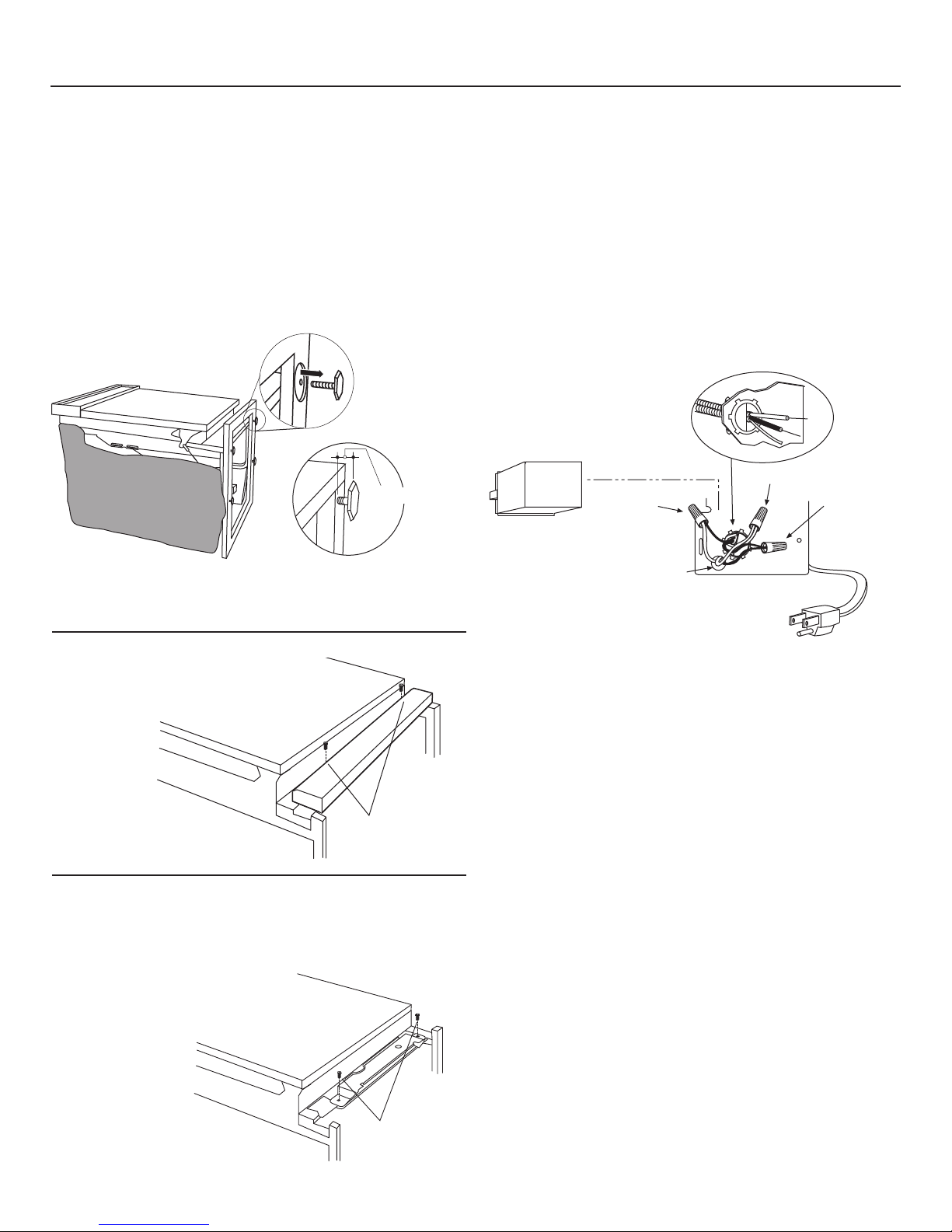
STEP 7 – INSTALL POWER CORD
Skip this step if dishwasher will be permanently connected
to the house electrical system.
In this step you will need the junction box cover and the
#10 x 1/2" hex-head screw from the screw kit set aside in
Step 1.
The power cord and connections must comply with the
National Electrical Code, Section 422 and/or local codes and
ordinances. Maximum power cord length is 6 feet. Power Cord
Kit WX09X70910, available for purchase from an authorized
GE Appliance Dealer, meets these requirements.
White
Ground
Black
• Screw leveling legs back into the dishwasher frame
approximately 1/8" from frame as shown.
STEP 5 – REMOVE TOEKICK
• Remove the 2 toekick screws
and toekick.
Set aside
for use in
Step 23.
AT\^eT!
Figure L
C^TZXRZBRaTfb
STEP 6 – REMOVE TOEKICK BRACE
Skip this step if your model does not have a sound upgrade
kit. If your model does have a sound upgrade kit, this brace
must be removed.
• Remove the 2 toekick brace
screws and
toekick brace.
Discard brace
and set
screws aside
for use in
Step 22.
Figure M
Remove 2
Toekick Screws
Figure N
• Install strain relief in junction box bracket.
• Insert power cord through strain relief and tighten.
• Make sure black, white and green dishwasher wires are
threaded through small hole in junction box bracket.
• Connect like-colored dishwasher and power cord wires. If
power cord wires are not color-coded, connect the ribbed
power cord wire to the white dishwasher wire, the smooth
power cord wire to the black dishwasher wire and the ground
to the green dishwasher wire. Use UL-listed wire nuts of
appropriate size.
• Install junction box cover set aside in Step 1, using #10 hexhead screw. Be sure wires are not pinched under the cover.
8
Page 9
Dishwasher Installation
Hose Clamp
Hose Stops
Pump Outlet
Check Valve
Do Not Remove
STEP 8 – INSTALL 90° ELBOW
• Wrap 90° elbow with thread seal tape.
• Install a 90° elbow onto the water valve.
Front of Dishwasher
Water Valve
Bracket
90°
Elbow
Fill
Hose
Thread
Figure O
• Do not overtighten the 90° elbow; water valve bracket could
bend or water valve fi tting could break.
• Position the end of the elbow to face the rear of the
dishwasher.
Seal Tape
STEP 9 – POSITION WATER LINE AND
HOUSE WIRING
• Position water supply
line and house wiring
on the fl oor of the
enclosure to avoid
interference with
base of dishwasher
and components
under dishwasher.
Figure P
$
FPcTa
;X]T
#
7^dbT
FXaX]V
$
#
%
STEP 10 – INSTALL DRAIN HOSE TO
DISHWASHER DRAIN PORT
In this step you will need the drain hose and clamp set aside
in Step 1.
• Stand dishwasher upright.
• Place drain hose clamp over 1-3/16" inside diameter end
of drain hose with the clamp screw positioned on the bottom
of the hose.
IMPORTANT – Prevent drain hose damage and
possible leaks. Be careful not to nick or cut the drain hose.
• Push the end of the drain hose over the drain pump outlet
being careful not to disturb the check valve. Refer to Figure Q.
• Seat the drain hose end against the hose stops on the pump
outlet.
• Position hose clamp against the front lip of the drain hose
and tighten clamp.
NOTE: Drain hose
supplied with dish washer is approximately 78" long.
If a longer hose is
needed, a 120" long
hose (10 feet) may
be purchased from
an authorized
GE appliance
dealer. The
10' long
hose is
part
number
GPF10L.
Figure Q
Tip: Avoid unnecessary service charges. Make a leak free
connection
Insert hose against stop on pump. Position clamp against front
lip of drain hose with clamp screw on bottom side of hose.
Tighten clamp to at least 15 inch-pounds of torque.
Tip: Reduce drain pump noise
Position drain hose clamp so screw is on the bottom side of the
hose. This will prevent noise caused by the clamp coming in
contact with the tub bottom. Refer to Figure Q.
9
Page 10

Dishwasher Installation
STEP 11 – INSERT DRAIN HOSE
THROUGH CABINET
• Position dishwasher in front of cabinet opening. Insert drain
hose into the hole in cabinet side. If a power cord is used,
guide the end through a separate hole.
Maximum Drain
Hose Length 10'
Insulation
Blanket
Figure R
Tip: Position water line and house wiring on the floor to avoid
interference with base of dishwasher.
Water
Line
Drain
Hose
House Wiring
(If Power Cord
is NOT Used)
Power Cord
(If Used)
STEP 12 – SLIDE DISHWASHER THREE-
FOURTHS OF THE WAY INTO
CABINET
IMPORTANT – DO NOT PUSH AGAINST FRONT PANEL
WITH KNEES. DAMAGE WILL OCCUR.
• Grasp the dishwasher by its sides and slide it into the opening
a few inches at a time.
3^=^c?dbW0VPX]bc
5a^]c3^^a?P]T[FXcW
:]TT3P\PVTc^CWT
3^^a?P]T[FX[[>RRda
Figure S
• As you proceed, pull the drain hose through the opening
under the sink. Stop pushing when the front of the
dishwasher is a few inches forward of adjacent cabinets.
• Make sure drain hose is not kinked under the dishwasher
and there is no interference with the water line, wiring or any
other component.
Tip: Make sure the dishwasher will fit in the cabinet. Check to
be sure the power cable, drain hose and hot water line are not
trapped behind the dishwasher. Utility lines trapped behind the
dishwasher prevent the dishwasher from being pushed fully
into the enclosure.
10
Page 11

Dishwasher Installation
STEP 13 – SLIDE DISHWASHER INTO
FINAL POSITION
• Push the dishwasher the rest of the way into the cabinet.
• Push the sides with your hands. Do not push the dishwasher
with your knee, as this will damage the door.
• Check that the tub insulation blanket does not get
“bunched up” or interfere with the springs as you slide it
into the cabinet.
• Center the dishwasher in the opening.
• Front of door panel should be fl ush with face of cabinet.
• Carefully open and close the door to ensure that the door
panel does not catch or rub on the cabinet frame. Refer
to Figure U below.
• If the door catches or rubs on the frame, reposition and/or
level the unit (see Step 14) until the door moves freely and
does not contact the cabinet frame.
Door
Fits and
Swings
Back
Behind
Cabinet
Frame
Special Considerations for Positioning
Top-Mount Control Models
The controls on these models are designed to be hidden by
your countertop. Align the dishwasher as shown in Figure
V. Leave a 1/2" minimum gap between the underside of the
countertop and the top of the dishwasher door as shown in
Figure W.
Use the leveling legs to increase or decrease the amount
of gap between the controls and the countertop.
For flush installations of the custom panel models, it may
be necessary to cut off the back panel of the tub insulation
blanket so that the dishwasher door panel can be aligned with
the kitchen cabinet panels.
IMPORTANT – Leave a 1/2" minimum gap between
the controls and the underside of the countertop to prevent
condensation and damage to the control panel from screw
heads.
Countertop
TIME REMAINING
Alignment
Figure U
Correct
Incorrect
Alignment
Door Catches on
Cabinet Frame
Controls Hidden
by Countertop
Figure V
Countertop
1/2"
Min.
Figure W
Dishwasher Door
11
Page 12

Dishwasher Installation
STEP 14 – LEVEL DISHWASHER
IMPORTANT – Dishwasher must be level for proper
dish rack operation and wash performance.
• For Top-Mount Control Models:
Make sure 1/2" minimum gap is maintained.
• For All Models:
Place level on door to check that the dishwasher is level
side to side. Remove lower
rack, place level on lower
rack track inside tub to
check that the
dishwasher is level
front to back.
Use
Level to
Check
Front
to Back
Figure X
Use
Level to
Check
Side
to Side
STEP 15 – SECURE DISHWASHER TO
COUNTERTOP OR CABINET
In this step you will need
the 2 Phillips special head
screws set aside in Step 1.
The dishwasher must be
secured to the countertop
or the cabinet sides. When
countertops are made of
wood, use Method 1. When
countertops are granite or
other materials that will not
accept screws, use Method
2 to secure dishwasher at the sides.
IMPORTANT –
Avoid unnecessary
service charges.
Drive screws straight
and flush. Protruding
screw heads will
scratch the top or
sides of the control
panel and can interfere with door closing.
BXST<^d]cX]V
1aPRZTcb
CdQ
5aP\T
Figure Z
Wood Cooktop
Screws
Figure AA
2^d]cTac^_
<^d]cX]V
1aPRZTcb
• If the dishwasher is not level, adjust the four leveling legs
as illustrated in Figure Y.
• If adjustment to the
right-rear leveling leg
is required, access it
by loosening the
junction box bracket
screw (through the
access hole) and
rotate bracket clockwise.
Junction Box
Turn Legs
Access Hole
to Adjust
Figure Y
• The dishwasher is properly leveled when the level indicator is
centered left to right and front to back. The dishwasher door
should close without hitting the sides of the tub,
• Replace the lower rack when leveling is complete.
Tip: Avoid unnecessary service charges for poor wash
performance and rack operation.
Pull the dish racks half way out. They should remain stationary.
Open and close the door. The door should fi t in the tub opening
without hitting the side of the tub. If the racks roll on their own,
or the door hits the side of the tub, relevel the dishwasher.
IMPORTANT – After leveling, verify that the
dishwasher is centered in the enclosure and the door does
not hit adjacent cabinets.
Method 1
Secure dishwasher to wood countertop
• Fasten the dishwasher to the underside of the countertop
with the 2 Phillips special head screws provided.
Method 2
Secure dishwasher with side-mounting brackets
• Remove plug buttons (one on each side).
• Install screws through the dishwasher side-mount bracket
and into the adjacent cabinet on each side. Reinstall plug
buttons.
Granite Countertop
Plug Buttons
Screws
Figure BB
Either Method–For Top-Mount Control Models.
Make certain 1/2" gap minimum is maintained.
• When step is complete, close dishwasher door and verify
that gap between countertop and top of dishwasher door is
at least 1/2".
Countertop
1/2"
Min.
Figure CC
Dishwasher Door
12
Page 13

Dishwasher Installation
ggpp
STEP 16 – CONNECT WATER SUPPLY
Connect water supply line to the 90° elbow.
• Slide compression nut, then ferrule over end of water line.
• Insert water line into 90° elbow.
• Slide ferrule against elbow and secure with compression nut.
IMPORTANT – Check to be sure that door spring does
not rub or contact the fill hose or water supply line. Test by
opening and closing the door. Reroute the lines if a rubbing
noise or interference occurs.
Compression Nut
Ferrule
90° Elbow
Figure DD
STEP 17 – CONNECT DRAIN LINE
The molded end of the drain hose will fit 5/8" through 1"
diameter inlet ports on the air gap, waste tee or disposer.
• Determine size of inlet port
• Cut drain hose connector on the marked line, if required, to fi t
the inlet port.
Cutting Line
1"
IMPORTANT: Do not cut corrugated
portion of hose
5/8"
Hot Water
Supply Line
90° Elbow
Door Spring
NOTE: TOTAL DRAIN HOSE LENGTH MUST NOT EXCEED 10' FOR
PROPER DRAIN OPERATION.
DRAIN LINE INSTALLATION
• Connect drain line to air gap, waste tee or disposer using
the previously determined method.
• Secure the drain hose to the air gap, waste tee or disposer
with clamps.
Method 1 – Air gap with waste tee or disposer
Insert the drain hose into the air gap as shown.
Waste Tee Installation
Figure GG
Method 2 – High Drain Loop with the Waste Tee or Disposer
Route the drain hose of the dishwasher to a minimum height of 32" from
the fl oor with the supplied hanger as shown.
32"
Min.
18"
Min.
Waste Tee Installation
Figure HH
Disposer Installation
18"
Min.
Disposer Installation
32"
Min.
Figure EE
• If a longer drain hose is required, and you did not purchase
10' long GPF10L drain hose, add up to 3-1/2' of length for a
total of 10' to the factory-installed hose. Use 5/8" or
7/8" inside diameter
hose and a coupler
to connect the
two hose ends.
Secure the
connection with
hose clamps.
Figure FF
7^bT2[P\_
2^d_[Ta
7^bT2[P\_
IMPORTANT – One of the above methods must be
used or dishwasher will not operate properly.
IMPORTANT – When connecting
drain line to disposer, check to be sure
that drain plug has been removed.
DISHWASHER WILL NOT DRAIN IF
PLUG IS LEFT IN PLACE.
Tip: Avoid unnecessary service call charges. Always be sure
disposer drain plug has been removed before attaching
dishwasher drain hose to the disposer.
AT\^eT
7^__Ta
?[dV
13
Page 14

Dishwasher Installation
■
■
■
■
■
■
■
■
■
■
■
■
■
■
■
■
STEP 18 – CONNECT POWER SUPPLY
Skip this step if dishwasher is equipped with power cord.
Verify that power is turned off at the source.
• Locate junction box cover set aside in Step 1.
• Secure house wiring to the back of the junction box with a
strain relief.
• Locate the three dishwasher wires, (white, black and green)
with stripped ends. Insert dishwasher wires through the small
hole in the junction box. Connect like-colored dishwasher and
power cable wires using UL-listed wire nuts of appropiate size.
• Install the junction box cover. Check to be sure that wires are
not pinched under the cover.
FWXcT
6a^d]S
Figure II
1[PRZ
STEP 19 – PRETEST CHECKLIST
Review this list after installing your dishwasher to
avoid charges for a service call that is not covered by your
warranty.
■ Check to be sure power is OFF.
■ Open door and remove all foam and paper packaging.
■ Locate the Owner’s Manual set aside in step 1.
■ Read the Owner’s Manual for operating instructions.
■ Check door opening and closing. If door does not open and
close freely, check for proper routing of spring cable over
pulley. If door drops or closes when released, adjust spring
tension. See Step 3, Figure J.
■ Check to be sure that wiring is secure under the dishwasher,
not pinched or in contact with door springs or other
components. See Step 9.
■ Check door alignment with tub. If door hits tub, level
dishwasher. See Step 14.
■ Pull lower rack out, about halfway. Check to be sure it does
not roll back or forward on the door. If the rack moves,
adjust leveling legs. See Step 14.
WARNING
If house wiring is not 2-wire with a ground
wire, a ground must be provided by the
installer.
When house wiring is aluminum, be sure
to use U.L.-listed anti-oxidant compound
and aluminum-to-copper connectors.
ADVERTENCIA
Si el cableado de la casa no es de 2 cables
con un cable de conexión a tierra, el
instalador debe suministrar una conexión
a tierra.
Cuando el cableado de la casa es en
aluminio, cerciórese de usar un compuesto
anti-oxidante aprobado por U.L. y un
compuesto de aluminio a cobre.
■ Check door alignment with cabinet. If door hits cabinet,
reposition or relevel dishwasher. See Steps 13, 14 and 15.
■ Check that door spring does not contact water line, fill hose
or other components. See Step 16.
■ Verify water supply and drain lines are not kinked or in
contact with other components. Contact with motor or
dishwasher frame could cause noise. See Steps 9 and 11.
■ Turn on the sink hot water faucet and verify water
temperature. Incoming water temperature must
be between 120°F and 150°F. A minimum of 120°F
temperature is required for best wash performance. See
“Prepare Hot Water Supply,” page 6.
■ Add 2 quarts of water to the bottom of the dishwasher to
lubricate the pump seal.
■ Turn on water supply. Check for leaks. Tighten connections
if needed.
■ Remove protective film if present from the control panel
and door.
■ Avoid service call charges by ensuring there is an air gap
or drain hose routed through the required 32" minimum
height.
14
Page 15

Dishwasher Installation
■
■
■
■
■
■
■
■
STEP 20 – DISHWASHER WET TEST
■ Turn on power supply (or plug power cord into outlet,
if equipped).
■ Start the unit to check for leaks.
Front-Mount Control Models:
– Close & latch door
– Push RINSE ONLY pad
– Push START/RESET pad one time
Top-Mount Control Models:
– Push RINSE ONLY pad
– Push START/RESET pad one time
– Close & latch door
■ Check to be sure that water enters the dishwasher. If water
does not enter the dishwasher, check to be sure that water
and power are turned on.
■ Check for leaks under the dishwasher. If a leak is found, turn
off power supply, then tighten connections. Restore power
after leak is corrected.
■ Check for leaks around the door. A leak around the door
could be caused by door rubbing or hitting against
adjacent cabinet. Reposition the dishwasher if necessary.
See Steps 13, 14 and 15.
STEP 22 – INSTALL SOUND UPGRADE KIT
IF EQUIPPED
Skip this step if your model does not have the
Sound Upgrade Kit.
• Locate sound upgrade kit set aside in Step 1 and the two
screws set aside in Step 6.
• Attach the plastic Sound Panel as shown in Figure LL using
the two screws. The lower set of mounting holes should be
used.
• Be sure the sound panel is seated in the notches on frame
as shown in Figure JJ.
■ The dishwasher will drain and turn off about 5 minutes after
it was started. Check drain lines. If leaks are found, turn off
power supply and correct plumbing as necessary. Restore
power after corrections are made. See Step 10
and 17.
■ Open dishwasher door and make sure most of the water
has drained. If not, check to be sure disposer plug has been
removed and/or air gap is clear. See Step 17. Also check
drain line to be sure it is not kinked.
■ Run the dishwasher through another “Rinse Only” cycle.
Check for leaks and correct if required.
STEP 21 – Set Water Hardness
Models with bulk dispenser only. Skip this step if your
dishwasher does not have the bulk dispense feature.
• Locate the hard water test strip set aside in Step 1.
• Remove strip from package.
• Turn on the hot water and hold the strip under the stream,
following the directions on the package.
• Use the value on the test strip to calibrate your dishwasher
for water hardness. Refer to the section titled "Water
Hardness Calibration" in your Owner's Manual for information
on how to calibrate your dishwasher.
Figure JJ
Sound panel is
located under
door panel.
with Foam
Plastic Sound Panel
Be sure that the sound panel
is seated in the notch in
the frame. (Both sides)
Attachment
Screws
15
Page 16

Dishwasher Installation
STEP 23 – INSTALL TOEKICK
• Locate toekick and screws set aside in step 5.
C^TZXRZ
0ccPRW\T]c
BRaTfb
Figure KK
• Replace the toekick and make sure it is against the fl oor.
• Insert and tighten the 2 toekick attachment screws. The
toekick should stay in contact with the fl oor to ensure quiet
dishwasher operation.
STEP 24 – LITERATURE
• Be sure to leave complete literature package, Installation
Instructions and product samples with the consumer.
SPECIFICATIONS SUBJECT TO CHANGE WITHOUT NOTICE
GE Consumer & Industrial
General Electric Company
Louisville, Kentucky 40225
GEAppliances.com
206C1559P199 31-30260 07-09 JR
Page 17

Appareils ménagers GE
imagination at work
STOP
Instructions d’installation
Lave-vaisselle encastré
Si vouz des questions, appelez 800.GE.CARES ou visitez notre site Web : GEAppliances.com
Au Canada, appelez le 1.800.561.3344 ou visitez : www.electromenagersge.ca
ARRÊT
Il faut lire soigneusement toutes ces instructions.
IMPORTANT – Il faut respecter tous les codes et
règlements.
• Remarque pour l’installateur – Il faut prendre soin de
laisser ces instructions pour le client et l’inspecteur local.
• Remarque pour le consommateur – Il faut garder ces
instructions avec le manuel d’utilisation, pour consultation
ultérieure.
• Niveau de compétence – L’installation de ce lave-vaisselle
demande des connaissances mécaniques, électriques
et de plomberie de base. L’installateur est responsable
de l’installation appropriée. La garantie des appareils
ménagers de GE ne couvre pas les défaillances du produit
causées par une mauvaise installation. Consulter les
renseignements dans la garantie.
• Durée d’installation – 1 à 3 heures. Les installations
initiales demandent plus de temps que les installations de
remplacement.
LIRE ATTENTIVEMENT.
IL FAUT GARDER CES INSTRUCTIONS.
AVANT DE COMMENCER
IMPORTANT – Le lave-vaisselle DOIT être installé de
manière à permettre la dépose ultérieure de l’enceinte afin de
permettre toute intervention.
Si le lave-vaisselle livré est endommagé, il faut contacter
immédiatement le concessionnaire ou l’entrepreneur de
construction.
Accessoires optionnels – Consulter la liste de nécessaires de
panneaux de finition dans le manuel d’utilisation.
SÉCURITÉ
Il faut lire et observer tous les avertissements (PRUDENCE
et ATTENTION) montrés dans ces instructions. Pendant
l’installation décrite dans ce livret, il faut porter des gants et
des lunettes de sécurité.
Modèles à cuve en acier inoxydable
Page 18

Préparation pour l’installation
PIÈCES FOURNIES AVEC LE KIT
D’INSTALLATION :
■ Deux vis spéciales à tête cruciforme n° 8-18 x 5/8 po,
pour fixer le lave-vaisselle au-dessous du plan de travail.
■ Un couvercle de boîte de jonction et une vis à tête
hexagonale n° 10-1/2 po
■ Finition latérale et supérieure
■ Kit d’accessoires de finition de panneau (non illustré)
(Uniquement pour les modèles à panneaux sur mesure)
■ Kit de réduction de bruit (certains modèles)
■ Tuyau de vidange de 198 cm (78 po), porte-tuyau de
vidange et collier de tuyau
■ Documentation, échantillons et/ou coupons de
réduction
■ Bande d’essai d’eau dure (modèles à distributeur en vrac)
MATÉRIAUX NÉCESSAIRES :
■ Bague, écrou de compression et coude à angle droit
(filetage externe de 3/8 po à une extrémité, l’autre
extrémité correspondant à l’alimentation d’eau)
■ Ruban d’étanchéité de filetage
■ Serre-fils sur la liste UL (3)
Matériaux uniquement requis en cas
d’installation initiale :
■ Dispositif anti-siphon pour le tuyau de vidange, si
nécessaire
■ Raccord en té pour la plomberie d’égout, si nécessaire
■ Câble électrique ou cordon d’alimentation
■ Colliers de tuyau à vis
■ Dispositif de réduction de tension pour les branchements
électriques
■ Robinet
■ Conduite d’eau en cuivre de 3/8 po minimum
■ Manchon de raccord pour rallonger le tuyau de vidange,
le cas échéant
■ Tuyau de vidange GPF10L (longueur de 3 m [10 pi]) si
nécessaire
Ensemble de vis
Vis spéciales à tête
cruciforme n° 8 de 5/8
po de long
Bande d’essai d’eau dure
(modèles à distributeur
en vrac)
Coude à angle droit,
bague et écrou de
compression
Raccord en
té d’égout
Câble électrique
(ou cordon d’alimentation,
si nécessaire)
Dispositif
anti-siphon
Vis pour boîte
J à tête à six
pans n° 10 –
1/2 po de long
Kit de réduction
de bruit (certains
modèles)
Robinet
Collier de tuyau
à vis
Pièces de finition
Porte-tuyau de
vidange
Tuyau de vidange
(198 cm) (78 po)
Ruban
d’étanchéité
de filetage
Tuyau d’eau chaude
Serre-fils (3)
Dispositif de
réduction de
tension
Finition latérale
Finition latérale
Finition supérieure
Couvercle de
boîte de jonction
Collier de tuyau
Tuyau de vidange
GPF10L de 3 m (10
pi) en option
Manchon
OUTILS NÉCESSAIRES :
■ Tournevis cruciforme
■ Tournevis à douille de 1/4 po et 5/16 po
■ Clé à molette de 15 cm (6 po)
■ Niveau
■ Équerre de menuisier
■ Mètre ruban
■ Lunettes de sécurité
■ Lampe de poche
■ Seau pour attraper l’eau lors de la purge du tuyau
■ Douille de 15/16 po
■ Gants
Pour les installations initiales
seulement :
■ Coupe-tube
■ Perceuse et mèches appropriées
■ Scie-cloche
2
Tournevis
cruciforme
Douille de
15/16 po
Gants
Tournevis à
douille de 5/16 po
et 1/4 po
Clé à molette
de 15 cm (6 po)
Lunettes de sécuritéLampe de poche
Seau Scie-cloche Perceuse et mèches
Niveau
Coupe-tube
Mètre ruban
Equerre de
menuisier
appropriées
Page 19

Préparation pour l’installation - Enceinte
Armoire
à l’équerre
et d’aplomb
Le sol DOIT être
au même niveau
que le sol de la pièce
Cette portion du
mur ne doit pas
avoir de
tuyaux ni de fils
La plomberie et les fils
électriques doivent entrer dans
la zone hachurée
88 cm (34-1/2 po) ±
6 mm (1/4 po)
dessous du plan
de travail au sol
61 cm
(24 po) minimum
61 cm
(24 po)
minimum
12,5 cm
(5 po)
12,5 cm
(5 po)
10 cm
(4 po)
10 cm
(4 po)
15 cm
(6 po)
minimum de 5 cm
(2 po)
Plan de travail
Lave-vaisselle
minimum de 72 cm
(28-3/8 po)
PRÉPARATION DE L’ENCEINTE DU
LAVE-VAISSELLE
AVERTISSEMENT
• L’ouverture de l’armoire non dégrossie doit avoir une largeur
et une profondeur d’au moins 61 cm (24 po) et une hauteur
de 87 cm (34-1/4 po) ± 6 mm (1/4 po) du sol à la surface du
dessous du plan de travail.
• Il ne peut y avoir ni tuyaux, ni ls électriques sur la paroi
arrière.
• Les armoires adjacentes doivent être à l’équerre et d’aplomb
pour assurer un encastrement parfait. Voir la figure A.
• En cas d’installation dans un coin, prévoir un dégagement
d’au moins 5 cm (2 po) entre le lave-vaisselle et le mur
adjacent.
• Prévoir un dégagement d’au moins 72 cm (28-3/8 po) devant
le lave-vaisselle pour permettre l’ouverture complète de la
porte. Voir la figure B.
Pour réduire le risque de choc
électrique, d’incendie ou de blessures,
l’installateur doit s’assurer, au moment
de l’installation, que le lave-vaisselle est
complètement enclos.
• Il faut installer le lave-vaisselle à moins de 3 m (10 pi) de
l’évier pour que l’écoulement soit adéquat.
• Le lave-vaisselle doit être entièrement enclos sur le haut, les
côtés et l’arrière.
• Le lave-vaisselle ne peut toucher aucune partie de l’enceinte.
Dégagements :
En cas d’installation dans un coin, prévoir
un dégagement d’au moins 5 cm (2 po)
entre le lave-vaisselle et le mur adjacent
ou un autre appareil électroménager.
Prévoir un dégagement d’au moins 72 cm
(28-3/8 po) devant le lave-vaisselle.
Figure B
Figure A
• Vérier que le sol à l’intérieur de l’ouverture d’armoire est
plane et à niveau avec le revêtement de sol de la cuisine. Ceci
facilite l’enlèvement du lave-vaisselle en cas de réparation
ultérieure, si nécessaire.
Conditions spéciales s’appliquant à un lave-vaisselle monté
sur une plate-forme
La plate-forme doit être plane et à niveau.
3
Page 20

Préparation pour l’installation - Vidange
81 cm
(32 po)
minimum
46 cm
(18 po)
minimum
46 cm
(18 po)
minimum
81 cm
(32 po) minimum
Enlever
le bouchon
de vidange
PRÉPARATION DE LA PLOMBERIE DE
VIDANGE
Exigences de vidange
• Le tuyau de vidange ne peut pas être plus de 3 m (10 pi)
de long.
• Une boucle de vidange élevée ou un dispositif anti-siphon
est requis. Voir ci-dessous.
Méthode de vidange
Le type d’installation de vidange est lié aux conditions suivantes :
• Est-ce que les codes ou règlements locaux exigent un
dispositif anti-siphon ?
• Est-ce que le raccord en té d’égout se trouve à moins de 46
cm (18 po) du sol ?
Si la réponse à une de ces questions est OUI, il faut utiliser un
dispositif anti-siphon. Se reporter à la méthode 1 (figure C) des
illustrations adjacentes.
Si la réponse est non aux deux questions, il faut utiliser soit un
dispositif anti-siphon, soit une boucle de vidange élevée. Se
reporter à la méthode 1 (figure C) ou la méthode 2 (figure D)
des illustrations adjacentes.
REMARQUE : La hauteur d’élévation du tuyau de vidange
ne peut dépasser 122 cm (48 po).
Conditions spéciales s’appliquant à un lave-vaisselle monté
sur plate-forme
En cas d’installation du lave-vaisselle sur une plate-forme, il
faut prévoir une boucle de vidange élevée d’au moins 81 cm
(32 po) au-dessus de la plate-forme en plus du dispositif antisiphon ou de la boucle de vidange prévu précédemment. Cette
mesure assure un écoulement adéquat de l’eau.
PRUDENCE :
Il FAUT utiliser un dispositif anti-siphon si le raccord du
tuyau de vidange au raccord en té d’égout ou au broyeur
à déchets est à moins de 46 cm (18 po) du niveau du sol. Le
lave-vaisselle risque de ne pas se vidanger correctement
et de s’endommager si le raccord de vidange n’est pas à
la bonne hauteur avec un dispositif anti-siphon ou une
boucle de vidange élevée d’au moins 81 cm (32 po).
MÉTHODE 1 – Dispositif anti-siphon avec raccord
en té d’égout ou de broyeur à déchets
Figure C
Installation avec un raccord
en té d’égout
Installation avec un
broyeur à déchets
MÉTHODE 2 – Boucle de vidange élevée avec un
raccord en té d’égout ou broyeur à déchets
Utiliser le porte-tuyau de vidange compris dans le kit de
montage pour suspendre le tuyau de vidange sous le plan de
travail. Ceci sera accompli à une étape ultérieure.
Figure D
Installation avec un raccord
en té d’égout
Installer le raccord en té d’égout ou le broyeur et le dispositif
anti-siphon selon les directives du fabricant.
Installation avec un
broyeur à déchets
Préparation de l’armoire pour l’installation du
tuyau de vidange
Percer un trou de 38 mm (1-1/2 po) dans la paroi de l’armoire
dans la zone hachurée indiquée à la figure A pour le passage
du tuyau de vidange. Vérifier que les bords du trou sont lisses.
Dans une étape ultérieure, il faut glisser le tuyau de vidange au
travers du trou pour le raccorder au drain.
IMPORTANT – Pendant le
branchement du tuyau de vidange
au broyeur à déchets, vérifier que
le bouchon de vidange a été enlevé.
Le lave-vaisselle ne peut pas se vider
si le bouchon est en place.
4
Page 21

Blanc
61 cm (24 po)
du mur
7,5 cm (3 po)
de l’armoire
Terre
Noi
Trou de 38 mm
(1-1/2 po)
de diamètre,
maximum
Emplacement
de la prise
de courant
Autre emplacement
possible de la
prise de courant
46 cm
(18 po)
46 cm
(18 po)
15 cm (6 po)
Préparation pour l’installation - Alimentation électrique
PRÉPARATION POUR LE BRANCHEMENT ÉLECTRIQUE
AVERTISSEMENT
SÉCURITÉ :
Enlever le fusible du circuit ou
déclencher le disjoncteur avant de
commencer l’installation. Avec cet
appareil, ne pas utiliser une rallonge
ou un adaptateur de prise.
Alimentation électrique
• Cet appareil doit avoir une alimentation en 120 V, 60 Hz, et
être branché à un circuit indépendant correctement mis à la
terre, protégé par un disjoncteur de 15 ou 20 A ou un fusible
temporisé.
• Le branchement doit être fait avec deux ls plus un l de
terre, homologués pour une température de 80 ºC (176 ºF).
• Si l’alimentation électrique n’est pas conforme à ces
conditions, appeler un électricien agréé avant de continuer.
Mise à la terre – Raccord permanent
Cet appareil doit être raccordé de façon permanente à un
réseau de fils métalliques mis à terre ou il faut installer un fil de
mise à terre avec les fils d’alimentation. Ce fil doit être branché
à la borne de terre de l’équipement ou à un fil sur l’appareil.
Instructions de mise à la terre – Modèles avec un cordon
d’alimentation
Cet appareil doit être mis à la terre. En cas de mauvais
fonctionnement ou de panne, la mise à la terre réduit le risque
de choc électrique en fournissant un passage de moindre
résistance au courant électrique. Cet appareil est équipé d’un
cordon d’alimentation avec un conducteur de mise à la terre
et une fiche de terre. Il faut brancher la fiche dans une prise
appropriée, installée et mise à la terre conformément aux
codes et règlements locaux.
AVERTISSEMENT
Le mauvais branchement du conducteur
de mise à la terre peut causer des
risques de choc électrique. En cas de
doute sur la mise à la terre de l’appareil,
consulter un électricien agrée ou
un technicien de réparation. Ne pas
modifier la fiche fournie avec l’appareil.
Figure E
Modèles équipés d’un cordon d’alimentation :Ne pas modifier
la fiche fournie avec l’appareil. Si la fiche ne correspond pas à
la prise, faire installer une prise appropriée par un électricien
qualifié.
Préparation de l’armoire et du passage des fils
• Les ls doivent entrer dans la cavité d’un côté ou de l’autre,
de l’arrière ou du sol, dans la zone hachurée dont les
dimensions sont détaillées à la figure A et qui est illustrée
ci-dessus.
• Couper un trou de 38 mm (1-1/2 po) de diamètre maximum
pour permettre le passage des fils d’alimentation électrique.
Le câble de branchement direct peut passer dans le même
trou que le tuyau de vidange et le tuyau d’eau chaude, si
c’est plus pratique. Si le mur de l’armoire est métallique, le
bord du trou doit être protégé par un œillet. REMARQUE : Le
cordon d’alimentation avec une fiche doit passer dans un
trou séparé.
Branchement électrique du lave-vaisselle
Le branchement électrique se fait sur le côté droit du
lave-vaisselle.
• Pour les branchements directs, le câble doit passer comme
montré à la figure E. Il doit y avoir une longueur de câble d’au
moins 61 cm (24 po) dépassant du mur arrière.
• Pour le branchement avec un cordon d’alimentation, installer
une prise à trois broches sur le mur arrière de l’armoire
d’évier, de 15 cm (6 po) minimum ou 46 cm (18 po) maximum
de l’ouverture, de 15 cm à 46 cm (6 à 18 po) au-dessus du
sol. La prise doit être accessible et, de ce fait, ne doit pas être
montée sur la paroi arrière de l’enceinte du lave-vaisselle.
5
Page 22

Préparation pour l’installation - Alimentation d’eau chaude
12,5 cm
(5 po)
12,5 cm
(5 po)
Devant
de l’armoire
Robinet
10 cm
(4 po)
10 cm
(4 po)
15 cm
(6 po)
5 cm (2 po) du sol
48 cm (19 po) du mur
5 cm (2 po)
de l’armoire
Trou de 38 mm
(1-1/2 po)
de diamètre
Eau
chaude
PRÉPARATION DE L’ALIMENTATION D’EAU
CHAUDE
Tuyau d’eau chaude
• Le tuyau peut entrer d’un côté ou de l’autre, de l’arrière ou du
sol, dans la zone hachurée montrée à la figure F.
• Le tuyau peut passer dans le même trou que le câble
électrique et le tuyau de vidange. Il est aussi possible de
couper un trou supplémentaire de 38 mm (1-1/2 po) de
diamètre uniquement pour le tuyau d’eau. En cas d’utilisation
d’un cordon d’alimentation avec une fiche, celui-ci doit passer
dans le trou d’alimentation électrique.
PRUDENCE :
La pression de la conduite d’alimentation d’eau chaude
doit être d’au moins 1,4 bar (20 psi). Une pression plus
faible risque de causer une fuite dans le robinet et des
dégâts d’eau.
Figure F
Branchement du tuyau d’eau
• Couper l’alimentation d’eau.
• Installer un robinet d’arrêt manuel dans un endroit
accessible - par exemple, sous l’évier. (En option, mais
fortement recommandé et peut être exigé par
les codes locaux.)
• La conduite d’eau se branche au côté gauche inférieur du
lave-vaisselle. Installer la conduite d’alimentation d’eau
chaude avec un tuyau en cuivre de minimum 9 mm (3/8 po).
Acheminer la conduite tel illustré à la figure F et l’amener à un
minimum de 48 cm (19 po) du mur arrière.
• Régler le chauffe-eau pour que l’eau sorte à une température
de 49 à 65 °C (120 à 150 °F).
• Purger la conduite d’eau pour éliminer tous les débris. Laisser
couler l’eau et les débris dans un seau.
• La pression de la conduite d’alimentation d’eau chaude doit
être entre 1,4 et 8,3 bar (20 et 120 psi).
6
Page 23

AUGMENTER
DIMINUER
UN SEUL TROU
Installation du lave-vaisselle
Pièce de finition
Pièce
de finition
Pièce
de finition
Augmenter
la tension
Diminuer
la tension
Utiliser ce
trou de
montage
Épaulement
Poulie
Acheminement correct
du câble du ressort
Acheminement incorrect
du câble du ressort
PRUDENCE :
Ne pas enlever la palette en bois avant d’être prêt à
installer le lave-vaisselle. Le lave-vaisselle bascule lorsque
la porte est ouverte sans la base.
ÉTAPE 1 : PIÈCES REQUISES POUR
L’INSTALLATION
Trouver les pièces suivantes dans le kit d’installation et les
mettre de côté aux fins d’utilisation aux étapes indiquées.
• Pièces de nition – étape 2
• Couvercle de boîte de jonction – étape 7 ou 18
• Tuyau de vidange et bride de xation – étape 10
• Ensemble de vis – étape 15
• Porte-tuyau de vidange – étape 17
• Manuel de l’utilisateur – étapes 19 et 24
• Bande d’essai d’eau dure – étape 21
• Kit de réduction de bruit (certains modèles) – étape 22
• Échantillons et/ou coupons de réduction – étape 24
ÉTAPE 2 – INSTALLATION DES PIÈCES
DE FINITION
Cette étape requiert les pièces de finition mises de côté à
l’étape 1.
• Presser la pièce de nition supérieure sur le haut du rebord
du bac. Commencer par le rebord droit et continuer vers la
gauche.
• Reprendre l’étape avec les pièces de nition gauche et droite
en allant de haut en bas.
• Ouvrir et fermer la porte pour vérier que la nition ne coince
pas et n’entrave pas le verrou ou les charnières de la porte.
Type 1 – Câble à un trou
Ajuster la tension en plaçant le crochet de ressort dans un des
trois trous du pied du bac.
Figure H
Type 2 – Câble à trois trous
Ajuster la tension en plaçant le crochet de ressort dans un des
trois trous du câble de la poulie.
Figure G
ÉTAPE 3 - VÉRIFICATION DE L’ÉQUILIBRE DE
LA PORTE
• En laissant le lave-vaisselle sur la palette en bois, ouvrir et
fermer la porte pour vérifier son équilibre.
• Il faut augmenter la tension des ressorts si la porte baisse
lorsqu’on la lâche. Il faut diminuer la tension si la porte s’élève
lorsqu’on la lâche.
• Il y a deux types de contrepoids et, par conséquent, deux
méthodes de réglage. Identifier le type de contrepoids et
ajuster la tension en conséquence. Remarque. - Utiliser le
câble pour l’ajustement s’il est muni de trois trous ; s’il n’a
qu’un seul trou, utiliser le pied du bac.
Figure I
Après avoir ajusté la tension du ressort, ouvrir et fermer
la porte pour vérifier son fonctionnement. Si la porte se
déplace difficilement ou le câble du ressort se coince, vérifier
l’acheminement du câble du ressort. Le câble doit reposer
entre les épaulements de la poulie du câble. Si le câble ne se
trouve pas sur la poulie : verrouiller la porte, relâcher la tension
du ressort et réacheminer le câble entre les épaulements de la
poulie. Voir figure J.
Figure J
7
Page 24

Installation du lave-vaisselle
Environ 3,2 mm
(1/8 po)
Enlever 2 vis
de la plinthe
Blanc
Terre
Noir
Enlever 2 vis
de la plinthe
ÉTAPE 4 : DÉPOSE DE LA PALETTE EN BOIS,
INSTALLATION DES PIEDS DE MISE À NIVEAU
IMPORTANT – Ne pas enlever la palette en
donnant des coups de pied ! Ceci risque d’endommager
le lave-vaisselle.
• Emmener le lave-vaisselle proche du lieu de son installation
et le basculer sur le dos.
• Enlever les quatre pieds de mise à niveau de dessous de la
palette avec une clé à douilles de 15/16 po.
• Enlever la palette.
Figure K
• Visser de nouveau les pieds de mise à niveau dans le cadre
du lave-vaisselle jusqu’à environ 3,2 mm (1/8 po) du cadre, tel
illustré.
ÉTAPE 7 : INSTALLATION DU CORDON
D’ALIMENTATION
Sauter cette étape si le lave-vaisselle doit être branché de
manière permanente sur le circuit électrique de la maison.
À cette étape, trouver le couvercle de la boîte de jonction et la
vis n° 10 de 1/2 po à tête à six pans mis de côté à l’étape 1.
Le cordon d’alimentation et les branchements doivent être
conformes au code national d’électricité et aux codes et
règlements locaux. La longueur maximale du cordon électrique
est de 2 mètres (6 pi). Le kit de cordon d’alimentation
WX09X70910, en vente chez les distributeurs agréés
d’appareils ménagers GE, satisfait à ces critères.
ÉTAPE 5 : DÉPOSE DE LA PLINTHE
• Enlever les deux vis de la plinthe et
la plinthe. Les mettre
de côté pour
utilisation
à l’étape 23.
Figure L
ÉTAPE 6 : DÉPOSE DU SUPPORT DE PLINTHE
Sauter cette étape si le modèle n’est pas équipé d’un kit de
réduction de bruit. Ce support doit être enlevé si le modèle
est équipé d’un kit de réduction de bruit.
• Enlever les deux vis de support
de plinthe et le support
de plinthe.
Jeter le support et
mettre les vis de
côté en vue
d’utilisation
à l’étape 22.
Figure M
8
Figure N
• Installer le réducteur de tension sur le support de la boîte de
jonction.
• Glisser le cordon électrique au travers du réducteur de
tension et serrer.
• Vérier que les ls noir, blanc et vert du lave-vaisselle passent
au travers du petit trou du support de boîte de jonction.
• Raccorder les ls du cordon électrique aux ls de couleur
correspondante du lave-vaisselle. Si les fils d’alimentation
électrique ne sont pas codés couleur, raccorder le fil
d’alimentation cannelé au fil blanc du lave-vaisselle, le fil lisse
au fil noir du lave-vaisselle et le fil de mise à terre au fil vert
du lave-vaisselle. Utiliser des serre-fils homologués UL de
taille appropriée.
• Attacher le couvercle de la boîte de jonction déposé à l’étape
1 avec la vis à tête à six pans n° 10. Vérifier que le couvercle
ne pince pas les fils.
Page 25

Installation du lave-vaisselle
Tuyau
d’eau
Fils de
la maison
13 cm
(5 po)
13 cm
(5 po)
10 cm
(4 po)
10 cm (4 po)
15 cm
(6 po)
Devant de lave-vaisselle
Coude
à angle
droit
Ruban d’étanchéité
de filet
Tuyau
de remplissage
Patte de
la vanne
ÉTAPE 8 : INSTALLATION DU COUDE À
ANGLE DROIT
• Mettre du ruban d’étanchéité de let sur le coude à angle
droit.
• Installer le coude à angle droit sur la vanne.
Figure O
• Ne pas serrer en excès le coude à angle droit, ceci pourrait
tordre la patte de la vanne ou briser le raccord de la vanne.
• Tourner le coude pour qu’il pointe vers l’arrière du lave-
vaisselle.
ÉTAPE 9 : MISE EN PLACE DU TUYAU D’EAU
ET DES FILS DE LA MAISON
• Mettre en place le tuyau
d’eau et les fils de
la maison sur le sol
de l’ouverture, afin
d’éviter toute
interférence avec
la base du lave-vaisselle
et des divers
éléments sous celui-ci.
Figure P
ÉTAPE 10 - RACCORDEMENT DU TUYAU DE
VIDANGE AU PORT DE VIDANGE DU LAVEVAISSELLE
Dans cette étape, il faut utiliser le tuyau de vidange et le collier
mis de côté à l’étape 1.
• Redresser le lave-vaisselle.
• Serrer le collier du tuyau de vidange sur l’extrémité à
diamètre intérieur de 1-3/16 po du tuyau de vidange avec la
vis de collier située au bas du tuyau.
IMPORTANT – Prévenir tous dommages au tuyau de
vidange et les fuites éventuelles. Prendre soin de ne pas
entailler ou couper le tuyau de vidange.
• Placer l’extrémité du tuyau de vidange par-dessus la sortie
de la pompe de vidange et appuyer en prenant soin de ne
pas entraver le clapet. Voir la figure Q.
• Placer l’extrémité du tuyau de vidange contre les butées de
tuyau de la sortie de pompe.
• Positionner le collier du tuyau contre le ressaut avant du
tuyau de vidange et serrer le collier.
REMARQUE :
Le tuyau de vidange
fourni avec le
lave-vaisselle
est environ 2 m
de long (78 po).
Si nécessaire, un
tuyau de 3 m
(10 pi) est
disponible chez
un distributeur
agréé
d’appareils
ménagers
GE. Le
tuyau de
3 m (10 pi)
porte le
numéro de
pièce GPF10L.
Figure Q
Conseil pour éviter les frais d’intervention inutiles. Vérifier
que tous les raccords sont étanches.
Placer le tuyau contre la butée de la pompe. Placer le collier
contre la lèvre avant du tuyau de vidange avec la vis du collier
au bas du tuyau. Serrer le collier à un couple d’au moins 15
pouces-livres.
Conseil pour réduire le bruit émis par la pompe de vidange
Placer le collier du tuyau de vidange de sorte que la vis se
trouve au bas du tuyau. Ceci empêche le bruit causé lorsque
le collier entre en contact avec le fond du bac. Se reporter à la
Figure Q.
9
Page 26

Installation du lave-vaisselle
Ne pas pousser contre
le panneau de la porte
avec le genou. Ceci endommage
le panneau de la porte.
Cordon
d’alimentation
(si utilisé)
Couverture
isolante
Longueur max.
du tuyau
de vidange : 3 m (10 pi)
Tuyau
d’eau
Fils de la maison
(si cordon
d’alimentation
N’EST PAS utilisé)
Tuyau
de vidange
ÉTAPE 11 : INSERTION DU TUYAU DE
VIDANGE À TRAVERS L’ARMOIRE
• Mettre le lave-vaisselle en position devant l’ouverture. Insérer
le tuyau de vidange dans le côté de l’armoire. Si un cordon
d’alimentation est utilisé, guider son extrémité dans un trou
séparé.
ÉTAPE 12 : GLISSER LE LAVE-VAISSELLE À
TROIS QUARTS DANS L’OUVERTURE DE
L’ARMOIRE
IMPORTANT – NE PAS POUSSER CONTRE LE PANNEAU
AVANT AVEC LE GENOU. CECI CAUSE DES DOMMAGES.
• Saisir le lave-vaisselle par les côtés et le glisser petit à petit
dans l’ouverture.
Figure R
Conseil: Placer le tuyau d’alimentation d’eau et le câblage
électrique de la maison sur le sol pour éviter d’entraver la base
du lave-vaisselle.
Figure S
• Au fur et à mesure du progrès, tirer le tuyau de vidange
dans l’ouverture sous l’évier. Arrêter de pousser quand le
lave-vaisselle dépasse d’une dizaine de centimètres devant
les armoires adjacentes.
• Vérier que le tuyau de vidange n’est pas pincé sous le
lave-vaisselle et qu’il n’y a aucune interférence entre le tuyau
d’eau et les fils et tout autre élément.
Conseil: S’assurer que le lave-vaisselle est adapté à l’armoire.
Vérifier que le fil d’alimentation, le tuyau de vidange et le
tuyau d’alimentation d’eau chaude ne se trouvent pas
coincés derrière le lave-vaisselle. Tout tuyau ou fil coincé
derrière le lave-vaisselle empêche l’encastrement complet du
lave-vaisselle dans l’enceinte.
10
Page 27

La porte
est placée
et bascule
derrière
le cadre
de l’armoire
Alignement
correct
La porte accroche
sur le cadre de l’armoire
Mauvais
alignement
Installation du lave-vaisselle
Plan de travail
Commandes cachées
par le plan de travail
TIME REMAINING
12,7 mm
min.
(1/2 po)
Plan de travail
Porte du lave-vaisselle
ÉTAPE 13 : PLACEMENT DU LAVE-VAISSELLE
À SA POSITION FINALE
• Pousser le lave-vaisselle tout à fait dans l’armoire.
• Pousser des mains sur les côtés. Ne pas utiliser le genou pour
ne pas endommager la porte.
• Pendant la mise en place dans l’armoire, vérier que la
couverture isolante du bac n’est pas « rebroussée » et qu’elle
n’interfère pas avec les ressorts.
• Centrer le lave-vaisselle dans l’ouverture.
• L’avant du panneau de porte doit être aligné sur le devant de
l’armoire.
• Ouvrir et fermer avec soin la porte pour vérier que le
panneau de la porte n’accroche pas ou ne frotte pas sur le
cadre de l’armoire. Voir la figure U ci-dessous.
• Si la porte accroche ou frotte sur le cadre, changer la position
ou mettre l’appareil de niveau (étape 14) jusqu’à ce que la
porte se déplace librement et n’est pas en contact avec le
cadre de l’armoire.
Points à considérer pendant le placement
de modèles à commandes montées sur
le haut
Les commandes de ces modèles sont conçues pour être
cachées par le plan de travail. Aligner le lave-vaisselle comme
illustré par la Figure V. Laisser un dégagement d’au moins 12,7
mm (1/2 po) entre le dessous du plan de travail et le haut de la
porte de l’appareil, tel illustré par la Figure W.
Utiliser les pieds de mise à niveau pour augmenter ou
diminuer la distance entre les commandes et le plan de travail.
Pour une installation à ras des modèles à panneaux sur
mesure, il peut être nécessaire de couper le panneau arrière
de la couverture d’isolation du bac pour pouvoir aligner le
panneau de la porte du lave-vaisselle sur les panneaux de
l’armoire de la cuisine.
IMPORTANT. – Laisser un dégagement d’au moins
12,7 mm (1/2 po) entre les commandes et le dessous du plan
de travail pour prévenir la condensation et les dommages
infligés au panneau de commande par les têtes de vis.
Figure U
Figure V
Figure W
11
Page 28

Installation du lave-vaisselle
Vérifier
d’un côté
à l’autre
avec un
niveau
Vérifier
de l’avant
à l’arrière
avec un
niveau
Trou
d’accès
Boîte
de jonction
Tourner les
pieds pour régler
Cadre
du bac
Pattes de
montage latéral
Pattes de
montage sur
le plan de travail
Vis
Plan de travail en bois
Vis
Bouchons
Plan de travail en granit
12,7 mm
min.
(1/2 po)
Plan de travail
Porte du lave-vaisselle
ÉTAPE 14 : MISE À NIVEAU DU
LAVE-VAISSELLE
IMPORTANT – Le lave-vaisselle doit être de niveau
pour obtenir un bon déplacement de l’égouttoir et du lavevaisselle.
• Modèles à commandes montées sur le haut :
Veiller à maintenir un dégagement d’au moins 12,7 mm
(1/2 po) (voir la Figure T).
• Tous les modèles
Mettre un niveau sur la porte
pour vérifier que
le lave-vaisselle
est horizontal, d’un côté
à l’autre. Enlever
l’égouttoir du bas ;
placer un niveau sur
la glissière de l’égouttoir
du bas à l’intérieur
du bac pour vérifier
que le lave-vaisselle
est à niveau de
l’avant à l’arrière.
• Si l’appareil n’est pas à niveau, ajuster les quatre pieds de
mise à niveau, tel illustré par la figure Y.
• S’il faut ajuster
le pied de mise à
niveau postérieur
droit, y accéder en
desserrant la vis de
support de la boîte de
jonction (à travers
le trou d’accès) et tourner
le support dans le sens
des aiguilles
d’une montre.
• Le lave-vaisselle est à niveau lorsque l’indicateur de niveau
est centré de gauche à droite et de l’avant vers l’arrière. La
porte du lave-vaisselle doit pouvoir se fermer sans toucher
les côtés du bac.
• Remettre en place l égouttoir du bas lorsque la mise à niveau
est terminée.
Conseil : Pour éviter les frais d’intervention inutiles causés
par un lavage inadéquat et le mauvais fonctionnement des
égouttoirs.
Tirer les égouttoirs vers le dehors jusqu’à mi-trajectoire. Ils
ne doivent pas bouger. Ouvrir et fermer la porte. La porte doit
recouvrir l’ouverture du bac sans toucher les côtés. Remettre
le lave-vaisselle à niveau si les égouttoirs se déplacent de leur
propre chef ou si la porte s’accroche sur les côtés du bac.
IMPORTANT – Après la mise à niveau, vérifier que
le lave-vaisselle se trouve centré dans l’enceinte et que la
porte ne bute pas contre les armoires adjacentes.
12
Figure X
Figure Y
ÉTAPE 15 : FIXATION DU LAVE-VAISSELLE
À L’ARMOIRE
À cette étape, il faut les
2 vis spéciales à tête
cruciforme mises de côté
avant l’étape 1.
Le lave-vaisselle doit être
fixé au plan de travail ou
aux côtés de l’armoire.
Utiliser la méthode nº 1
quand le plan de travail
est en bois. Quand le plan
de travail est en granite
ou autre matériau qui
n’accepte pas les vis,
Figure Z
utiliser la méthode nº 2
pour fixer le lave-vaisselle
sur les côtés.
IMPORTANT –
Éviter les frais
d’intervention inutiles.
Enfoncer les vis tout droit
et de niveau. Des têtes
de vis qui dépassent
rayent le dessus ou les
côtés du panneau de
commande et peuvent
interférer avec la fermeture
de la porte.
Méthode 1
Fixation du lave-vaisselle au plan de travail en bois
• Avec les deux vis spéciales à tête cruciforme fournies, visser
le lave-vaisselle sur le dessous du plan de travail.
Méthode 2
Fixation du lave-vaisselle avec les pattes de montage
latérales
• Enlever les bouchons (un de chaque côté).
• Mettre les vis à travers le lave-vaisselle et dans l’armoire
adjacente, de chaque côté. Remettre les boutons en place.
Figure BB
N’importe quelle méthode – Pour les modèles à commandes
montées sur le haut. Veiller à maintenir un dégagement
d’au moins 12,7 mm (1/2 po).
• À la fin de l’étape, fermer la porte du lave-vaisselle et vérifier
qu’il y a un dégagement d’au moins 12,7 mm (1/2 po) entre
le plan de travail et le haut du lave-vaisselle.
Figure CC
Figure AA
Page 29

Installation du lave-vaisselle
Enlever
le bouchon
Coude à
angle droit
Coude à
angle droit
Bague
Ressort de porte
Tuyau
d’alimentation
d’eau chaude
Ecrou de compression
Collier
Manchon
Collier
Ligne de coupe
1"
5/8"
IMPORTANT: Il ne faut pas couper la
portion ondulée du tuyau.
46 cm min.
(18 po)
81 cm min.
(32 po)
81 cm min.
(32 po)
46 cm min.
(18 po)
ÉTAPE 16 : BRANCHEMENT DE
L’ALIMENTATION D’EAU
Brancher le tuyau d’alimentation d’eau au coude à angle droit.
• Glisser l’écrou de compression et ensuite la bague sur
l’extrémité du tuyau d’eau.
• Insérer le tuyau d’eau dans le coude à angle droit.
• Glisser la bague contre le coude et serrer l’écrou de
compression.
IMPORTANT – Ouvrir et fermer la porte pour
vérifier que le ressort de la porte ne frotte pas ou n’est
pas en contact avec le tuyau de remplissage ni le tuyau
d’alimentation d’eau. Changer le passage des tuyaux s’il y a
un bruit de frottement ou une interférence.
Figure DD
ÉTAPE 17 : BRANCHEMENT DU TUYAU
DE VIDANGE
L’extrémité moulée du tuyau de vidange se branche sur l’orifice
d’admission de 5/8 po à 1 po de diamètre, du raccord d’espace
d’air, du raccord en té d’égout ou du broyeur à déchets.
• Déterminer la taille de l’orice d’admission.
• Couper le connecteur du tuyau de vidange à la ligne
marquée, selon le besoin, pour installation sur l’orifice
d’admission.
REMARQUE : POUR OBTENIR UNE BONNE VIDANGE, LA
LONGUEUR TOTALE DU TUYAU DE VIDANGE NE DOIT PAS
DÉPASSER 3 m (10 pi).
INSTALLATION DU TUYAU DE VIDANGE
• Brancher le tuyau de vidange sur le dispositif anti-siphon, le
raccord en té d’égout ou le broyeur à déchets, en utilisant la
méthode indiquée précédemment.
•Monter avec des colliers le tuyau de vidange sur le dispositif
anti-siphon, le raccord en té d’égout ou le broyeur à déchets.
Méthode nº 1 – Dispositif anti-siphon avec raccord en té
d’égout ou broyeur à déchets
Raccorder le tuyau de vidange au dispositif anti-siphon, tel
illustré.
Installation avec un raccord
en té d’égout
Figure GG
Méthode 2 – Boucle de vidange élevée avec raccord en té
d’égout ou broyeur à déchets
Acheminer le tuyau de vidange de l’appareil à une élévation minimale
de 81 cm (32 po) du sol en utilisant le porte-tuyau de vidange fourni, tel
illustré.
Installation avec un raccord
en té d’égout
Figure HH
Installation avec un
broyeur à déchets
Installation avec un
broyeur à déchets
Figure EE
• Si le tuyau de vidange est trop court et le tuyau de vidange
GPF10L n’a pas été acheté, une longueur de tuyau
de maximum un mètre (environ 3 pi) peut être
ajoutée pour obtenir un tuyau de 3 mètres (10 pi) de long.
Utiliser un tuyau de 5/8 ou 7/8 po de diamètre interne et un
manchon pour
brancher les deux
extrémités de
tuyaux. Maintenir
le manchon en
place avec
des colliers.
Figure FF
IMPORTANT – Il faut utiliser l’une des deux méthodes
précédentes pour assurer le fonctionnement correct du
lave-vaisselle.
IMPORTANT – En cas de
branchement du tuyau d’égout
au broyeur à déchets, vérifier
que le bouchon de vidange a été
enlevé. LE LAVE-VAISSELLE NE
SE VIDE PAS SI LE BOUCHON
EST EN PLACE.
Conseil: Il faut éviter les frais d’intervention inutiles. Il faut
toujours s’assurer que le bouchon de vidange a été enlevé
avant de brancher le tuyau de vidange du lave-vaisselle au
broyeur à déchets.
13
Page 30

Installation du lave-vaisselle
Blanc
Terre
Noir
ÉTAPE 18 : BRANCHEMENT DE
L’ALIMENTATION ÉLECTRIQUE
Sauter cette étape si le lave-vaisselle est équipé d’un cordon
d’alimentation. Vérifier que le circuit est hors tension
• Prendre le couvercle de la boîte de jonction rangé à l’étape 1.
• Attacher les ls de la maison au bas de la boîte de jonction à
l’aide du dispositif d’élimination des contraintes.
• Identier les trois ls du lave-vaisselle avec les extrémités
dénudées (blanc, noir et vert). Insérer les fils du lave-vaisselle
dans le petit trou de la boîte de jonction. Raccorder les fils
du cordon électrique aux fils de couleur correspondante du
lave-vaisselle avec des coinceurs à câble homologués UL de
taille appropriée.
• Installer le couvercle de la boîte de jonction. Vérier que les
fils ne sont pas pincés sous le couvercle
Figure II
AVERTISSEMENT
Si le circuit de la maison n’est pas
un circuit à deux fils plus fil de terre,
l’installateur doit installer un fil de
terre. Quand le circuit de la maison
est en aluminium, il faut prendre soin
d’utiliser une pâte antioxydante et des
connecteurs aluminium à cuivre sur
la liste UL.
ÉTAPE 19 : LISTE DE VÉRIFICATION AVANT
DE FAIRE LES ESSAIS
Examiner cette liste après l’installation du lave-vaisselle
pour éviter les frais d’intervention qui ne sont pas couverts
par la garantie
■ Vérifier que le système est hors tension.
■ Ouvrir la porte et enlever tout le conditionnement en
mousse et papier.
■ Trouver le Manuel d’utilisation rangé à l’étape 1.
■ Lire les instructions d’utilisation dans le Manuel d’utilisation.
■ Vérifier l’ouverture et la fermeture de la porte. Si la
porte ne s’ouvre et ne se ferme pas facilement, vérifier
l’acheminement du câble de ressort sur la poulie. Si la porte
tombe ou s’élève lorsqu’on la lâche, ajuster la tension du
ressort. Voir étape 3, figure J.
■ Vérifier que les fils sont bien en place sous le lave-vaisselle,
qu’ils ne sont pas pincés ni en contact avec les ressorts de
porte ni autres éléments. Consulter l’étape 9.
■ Vérifier l’alignement de la porte par rapport au bac, et que
le lave-vaisselle est de niveau. Consulter l’étape 14.
■ Sortir l’égouttoir du bas, à moitié chemin. Vérifier qu’il ne
recule ni n’avance. Si l’égouttoir se déplace, régler les pieds
de mise à niveau. Consulter l’étape 14.
■ Vérifier l’alignement de la porte par rapport à l’armoire. Si
la porte touche l’armoire, repositionner le lave-vaisselle et
régler les pieds de mise à niveau. Consulter l’étapes 13, 14
et 15.
■ Veiller à ce que le ressort de porte ne soit pas en contact
avec le tuyau de remplissage ou d’alimentation d’eau ou
avec d’autres composants. Consulter l’étape 16.
■ Vérifier que le tuyau d’alimentation d’eau et le tuyau de
vidange ne sont pas pincés ni en contact avec d’autres
composants. Le contact avec le moteur ou le lave-vaisselle
peut causer des bruits. Consulter l’étapes 9 et 11.
■ Ouvrir le robinet d’eau chaude d’évier et vérifier la
température de l’eau. L’eau d’alimentation doit avoir
une température entre 49 et 65 ºC (120 et 150 ºF). Il faut
une température d’au mois 49 ºC (120 ºF) pour obtenir le
meilleur rendement du lave-vaisselle. Consulter
« Préparation du tuyau d’eau chaude », page 6.
14
■ Ajouter deux litres d’eau au fond du lave-vaisselle pour
lubrifier le joint de la pompe.
■ Ouvrir le robinet d’eau. Vérifier qu’il n’y a pas de fuites.
Serrer les branchements selon le besoin.
■ Enlever, du panneau de commande et de la porte, la
pellicule de protection, si elle est présente.
■ Éviter les frais de service en contrôlant qu’un dispositif
anti-siphon ou un tuyau de vidange est installé à la hauteur
minimale requise de 81 cm (32 po).
Page 31

Installation du lave-vaisselle
Panneau d’insonorisation
en plastique avec mousse
Vis de fixation
Vérifier que le panneau
d’insonorisation est assis
dans les fentes du cadre (les deux côtés)
Le panneau
d’insonorisation se
trouve sous le
panneau de la porte.
ÉTAPE 20 : ESSAI DU LAVE-VAISSELLE AVEC
DE L’EAU
■ Mettre le circuit sous tension (ou brancher le cordon
d’alimentation dans la prise de courant, si installée).
■ Mettre le lave-vaisselle en marche pour vérifier qu’il n’y a
pas de fuites
Modèles à commandes sur le devant
- fermer et verrouiller la porte ;
- appuyer sur la touche RINSE ONLY (uniquement rinçage) ;
- appuyer une seule fois sur la touche START/RESET
(démarrage/réinitialisation)
Modèles à commandes montées sur le haut :
- appuyer sur la touche RINSE ONLY (uniquement rinçage) ;
- appuyer une seule fois sur la touche START/RESET
(démarrage/réinitialisation) ;
- fermer et verrouiller la porte.
■ Vérifier que l’eau entre dans le lave-vaisselle. Si l’eau
n’entre pas dans le lave-vaisselle, vérifier que le robinet
d’alimentation est ouvert et que le circuit est sous tension.
■ Vérifier qu’il n’y a pas de fuites sous le lave-vaisselle. S’il y
a une fuite, couper l’alimentation électrique et serrer les
branchements. Remettre le lave-vaisselle sous tension
après avoir éliminé les fuites.
■ Vérifier qu’il n’y aucune fuite autour de la porte. Une fuite
autour de la porte peut être causée par un frottement de la
porte ou un impact avec l’armoire adjacente. Repositionner
le lave-vaisselle si nécessaire. Consulter les étapes 13, 14 et
15.
■ Le lave-vaisselle se vide et s’arrête environ 5 minutes après
le démarrage. Vérifier les tuyaux de vidange. En cas de fuite,
couper le courant et corriger le problème de plomberie, le
cas échéant. Remettre sous tension après la réparation.
Voir les étapes 10 et 17.
■ Ouvrir la porte du lave-vaisselle et vérifier que la plus
grande partie de l’eau s’est écoulée. Si ce n’est pas le cas,
vérifier que le bouchon du broyeur a été enlevé et/ou que
le dispositif anti-siphon est libre de débris. Voir étape 17.
Vérifier également que le tuyau de vidange n’est pas plié.
■ Faire passer le lave-vaisselle par un autre cycle de « Rinse
Only » (rinçage seulement). Vérifier qu’il n’y a pas de fuite
et corriger selon le besoin
ÉTAPE 22 – INSTALLATION DU KIT DE
RÉDUCTION DE BRUIT, LE CAS ÉCHÉANT
Sauter cette étape si le modèle n’est pas équipé du kit de
réduction de bruit.
• Prendre le kit de réduction de bruit mis de côté à l’étape 1 et
les deux vis mis de côté à l’étape 6.
• Attacher le panneau d’insonorisation en plastique avec les
deux vis, comme illustré dans la figure LL. Il faut utiliser les
deux trous de montage inférieurs.
• Vérier que le panneau d’insonorisation est assis dans les
fentes du cadre, comme illustré dans la figure JJ.
ÉTAPE 21 – RÉGLAGE DE LA DURETÉ DE L’EAU
Uniquement les modèles à distributeur en vrac. Sauter cette
étape si le modèle n’est pas équipé d’un distributeur en vrac.
• Prendre la bande d’essai d’eau dure rangée à l’étape 1.
• La dépouiller de son emballage.
• Allumer l’eau chaude et maintenir la bande sous le jet d’eau
conformément aux directives de l’emballage.
• Utiliser la valeur de la bande d’essai pour calibrer la dureté de
l’eau du lave-vaisselle. Se reporter à la section Intitulée
« Calibrage de la dureté de l’eau » du Manuel de l’utilisateur
pour en savoir plus concernant le calibrage du lave-vaisselle
Figure JJ
15
Page 32

Vis de
fixation
Plinthe
Installation du lave-vaisselle
ÉTAPE 23 – INSTALLATION DE LA PLINTHE
• Prendre la plinthe et les vis rangés à l’étape 5.
Figure KK
• Remettre la plinthe en place en vériant que le bord inférieur
se trouve contre le sol.
• Serrer les deux vis de xation de plinthe. La plinthe doit
demeurer en contact avec le sol pour assurer que le
lave-vaisselle fonctionne en silence.
ÉTAPE 24 - DOCUMENTATION
• Prendre soin de laisser au consommateur l’enveloppe
complète de documentation, les instructions d’installation et
les échantillons de produit.
LES DONNÉES TECHNIQUES PEUVENT CHANGER SANS PRÉAVIS
GE Consumer & Industrial
General Electric Company
Louisville, Kentucky 40225
GEAppliances.com
206C1559P199 31-30260 07-09 JR
 Loading...