

GE GHDS830GD0WS, GHDS830GD1WS, GHDS835GD0MC, GHDS835GD1MC, GTDL740GD0WW Installation Guide
...Page 1
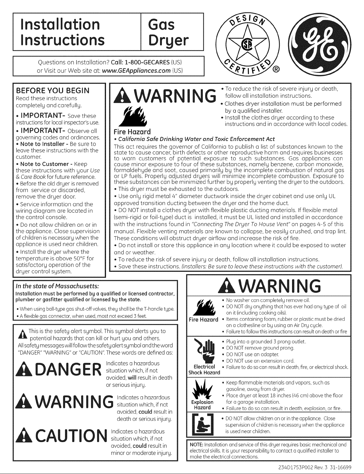
Installation
GGs
Instructions
Questions on Installation? Call: 1-800-GECARES (US)
or Visit our Web site at: www.GEAppliunces.com (US)
BEFORE YOU BEGIN
Read these instructions
completely and carefully.
- IMPORTANT- Savethese
instructionsforlocalinspector'suse.
- IMPORTANT- Observe all
governing codes and ordinances.
- Note to Installer- Be sure to
leave these instructions with the
customer.
Note to Customer - Keep
these instructions with gour Use
& Core Book for future reference.
Before the old drger is removed
from service or discorded,
remove the dryer door.
Service information and the
wiring diagram ore located in
the control console.
Do not allow children on or in
the appliance. Close supervision
of children is necessurg when the
appliance is used near children.
Install the dryer where the
temperature is above 50°F for
satisfactory operation of the
dryer control system.
rger
1
To reduce the risk of severe injury or death,
I G
Fire Hazard
, California Safe Drinking Water and Toxic Enforcement Act
This oct requires the governor of California to publish o list of substances known to the
state to cause cancer, birth defects or other reproductive harm and requires businesses
to worn customers of potential exposure to such substances. Gas appliances con
cause minor exposure to four of these substances, namely benzene, carbon monoxide,
formoldehgde and soot, caused primarily bg the incomplete combustion of natural gas
or LP fuels. Properlg adjusted drgers will minimize incomplete combustion. Exposure to
these substances con be minimized further bg properly venting the dryer to the outdoors.
- This dryer must be exhausted to the outdoors.
- Use only rigid metal 4" diameter ductwork inside the dryer cabinet and use only UL
approved transition ducting between the dryer and the home duct.
- DO NOTinstall o clothes dryer with flexible plastic ducting materials. Ifflexible metal
(semi-rigid or foil-tgpe) duct is installed, it must be UL listed and installed in accordance
with the instructions found in "Connecting The Dryer To House Vent" on pages 4-5 of this
manual. Flexible venting materials ore known to collapse, be easily crushed, and trap lint.
These conditions will obstruct drger airflow and increase the risk of fire.
- Do not install or store this appliance in ong location where it could be exposed to water
and or weather.
- To reduce the risk of severe injury or death, follow oil installation instructions.
- Save these instructions. (Installers: Be sure to leave these instructions with the customer).
follow oil installation instructions.
Clothes dryer installation must be performed
by aqualified installer.
Install the clothes dryer according to these
instructions and in accordance with local codes.
In the state of Massachusetts:
Installation must be performed by a qualified or licensed contractor,
plumber or gosfitter qualified or licensed bg the state.
• When using ball-type gas shut-off valves,they shall bethe T-handle type.
• A flexiblegas connector, when used,most not exceed 3feet.
_lk Thisis the safety alert symbol. Thissymbol alerts you to
potential hazards that con killor hurt you and others.
Allsafety messageswillfollowthesafety alert symbol andtheword
"DANGER""WARNING"or "CAUTION".Thesewords ore defined as:
Indicates o hazardous
situation which, if not
avoided, will resultindeath
or serious injury.
Indicates o hazardous
G
situation which, if not
avoided, could result in
death orserious injury.
Indicates o hazardous
situation which, ifnot
avoided, could result in
minor or moderate injury.
, WAR
CAUTIO
GER
I
A WA I
• No washer con completely remove oil.
• DONOTdry anything that has ever had any type of oil
on it (including cooking oils).
Fire Hazard
Electrical
Shock Hazard
Explosion
Hazard
NOTE:Installation and service of this dryer requires basicmechanical and
electricalskills, ttisyour responsibility to contact a qualified installer to
makethe electrical connections.
Items containing foam, rubber or plastic must be dried
on a clothesline or by usingon AirDry cycle.
• Failureto follow this instructions con resulton death or fire
Plug into a grounded 5 prong outlet.
DONOTremove ground prong.
DONOTuse an adapter.
DONOTuse an extension cord.
Failureto do so can resultin death, fire,or electrical shock.
• Keepflammable materials and vapors, such as
gasoline, away from @yen
• Place dryer at least 18 inches (/46cm) above the floor
for agarage installation.
Failureto do so can result in death, explosion, or fire.
DONOTallow children on or inthe appliance. Close
supervision of children isnecessary when the appliance
isused near children.
G
254D!755PO02 Rev. 5 51-16699
Page 2
Installation Instructions
Minimum Clearance in Alcove or Closet Installation
Minimum clearance to combustible surfaces and for air opening are: 0 in. clearance both sides, 3 in.front, 7 in. top and 3 in. rear.
Consideration must be given to provide adequate clearance for installation and service
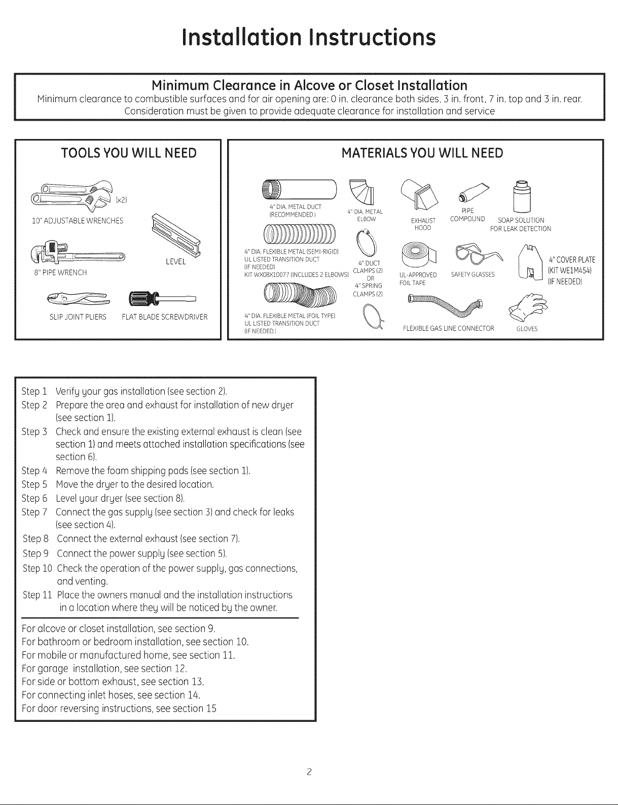
TOOLS YOU WILL NEED
(x2)
10" ADJUSTABLE WRENCHES
8" PIPE WRENCH
SLIPJOINT PLIERS FLAT BLADE SCREWDRIVER
Step i
Step 2
Step 3
Step4
Step 5
Step 6
Step 7
Step 8
Step 9
Step10
Stepii
Verifg gour gas installation (seesection 2).
Prepare the area and exhaust for installation of new drger
(seesection!).
Checkand ensure the existing external exhaust isclean (see
section 1)and meets attached installation specifications (see
section 6).
Removethe foam shipping pads (seesection 1).
Move the drger to the desired location.
Levelgour drger (see section 8).
Connect the gas supplg (seesection 3) and check for leaks
(seesection 4).
Connect the external exhaust (seesection 7).
Connect the power supplg (seesection 5).
Checkthe operation of the power supplg, gas connections,
and venting.
Placethe owners manual and the installation instructions
in a location where theg will benoticed bgthe owner.
LEVEL
MATERIALS YOU WILL NEED
%
4" DIA. METAL DUCT
(RECOMMENDED }
4" DIA. FLEXIBLE METAL(SEMI RIGID)
UL LISTED TRANSITION DUCT
(IFNEEDED) CLAMPS (2)
KIT WXO8XIOO7 ? (INCLUDES 2 ELBOWS) OR
zi" DIA. FLEXIBLE METAL (FOIL TYPE) (C"'_
UL LISTED TRANSITION DUCT
(IFNEEDED.)
4" DIA METAL
ELBOW
4" DUCT
CLAMPS (2)
4" SPRING
EXHAUST
HOOD
UL-APPROVED SAFETY GLASSES
FOILTAPE
FLEXIBLE GAS LINE CONNECTOR
PiPE
COHPOUND SOAPSOLUTION
FORLEAKDETECTION
4" COVERPLATE
(KITWEIM454)
(IFNEEDED)
GLOVES
Foralcove or closet installation, seesection 9.
Forbathroom or bedroom installation, see section 10.
Formobile or manufactured home, see section 11.
Forgarage installation, see section 12.
Forside or bottom exhaust, see section 13.
Forconnecting inlet hoses,see section 14.
Fordoor reversing instructions, see section 15
Page 3
Installation Instructions
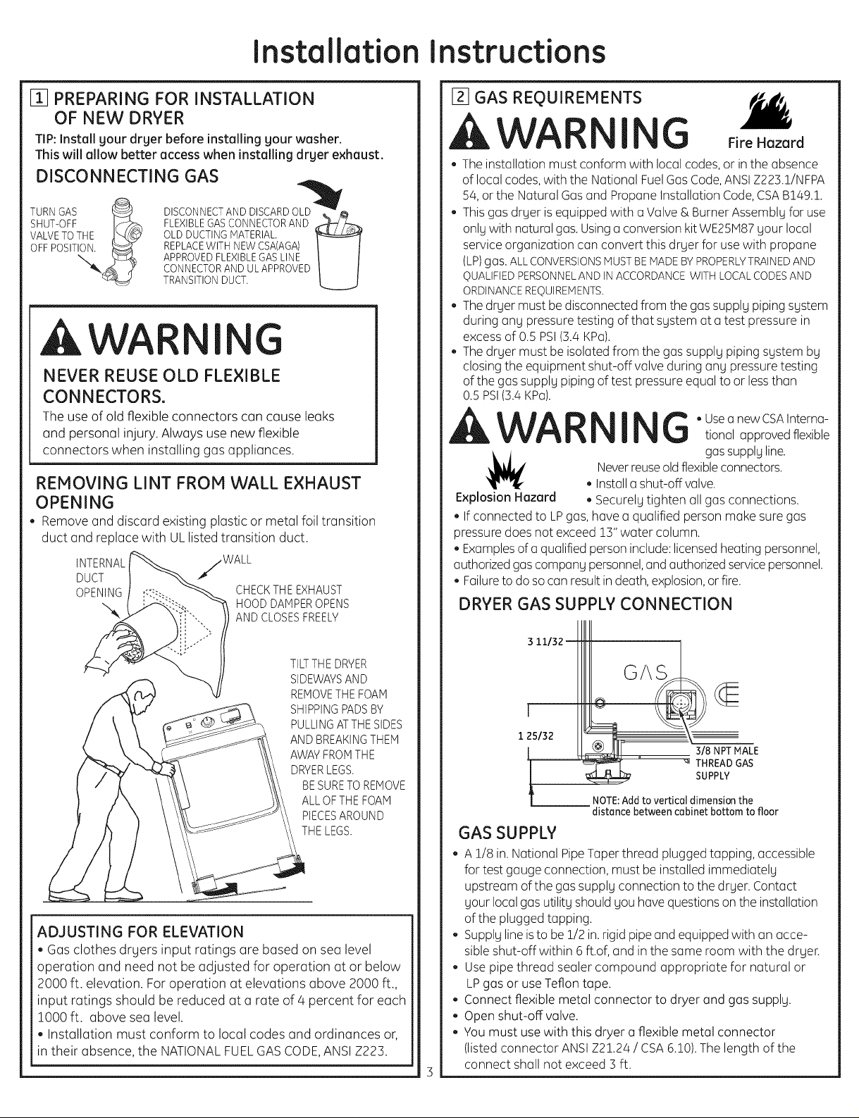
[_ PREPARING FOR INSTALLATION
OF NEW DRYER
TIP: Install your dryer before installing your washer.
This will allow better access when installing dryer exhaust.
DISCONNECTING GAS
TURNGAS
SHUT-OFF I_2_
VALVETOTHE _\d_
OFFPOSIT_._
DISCONNECTANDDISCARDOLD'_
FLEXIBLEGASCONNECTORAND ,_--/_
OLDDUCTINGMATERIAL.
REPLACEWITHNEWCSA(AGA)
APPROVEDFLEXIBLEGASLINE
CONNECTORANDULAPPROVED
TRANSITIONDUCT.
U
,AWA I G
NEVER REUSE OLD FLEXIBLE
CONNECTORS.
The use of old flexible connectors can cause leaks
and personal injury. Always use new flexible
connectors when installing gas appliances.
REMOVING LINT FROM WALL EXHAUST
OPENING
, Remove and discard existing plastic or metal foil transition
duct and replace with UL listed transition duct.
INTERNAL jWALL
DUCT
OPENING CHECKTHEEXHAUST
HOODDAMPEROPENS
ANDCLOSESFREELY
[_ GAS REOUIREMENTS
AWAR I G FireHazard
• The installation must conform with local codes, or in the absence
of local codes, with the National Fuel Gas Code, ANSI Z223.!/NFPA
54, or the Natural Gas and Propane Installation Code, CSA B149.!.
• This gas drger is equipped with a Valve & Burner Assemblg for use
onlg with natural gas. Using a conversion kit WE25ivI87 gour local
service organization can convert this drger for use with propane
(LP)gas. ALLCONVERSIONSMUSTBEMADEBYPROPERLYTRAINEDAND
QUALIFIEDPERSONNELANDINACCORDANCEWITHLOCALCODESAND
ORDINANCEREQUIREMENTS.
- The drger must be disconnected from the gas supplg piping sgstem
during ang pressure testing of that sgstem at a test pressure in
excess of 0.5 PSI(3.4 KPa).
The drger must be isolated from the gas supplg piping sgstem bg
closing the equipment shut-off valve during ang pressure testing
of the gas supplg piping of test pressure equal to or lessthan
0.5 PSI(3.4 KPa).
AWAR I G ° Usea newcSAInterna-
,_ gas supplg line.
Explosion Hazard • Securelg tighten all gas connections.
• If connected to LPgas, have a qualified person make sure gas
pressure does not exceed !3" water column.
• Examples of a qualified person include: licensed heating personnel,
authorized gas compang personnel, and authorized service personnel.
• Failure to do so can result indeath, explosion, or fire.
Never reuse old flexible connectors.
• Install a shut-offvalve.
DRYER GAS SUPPLY CONNECTION
tional approved flexible
TILTTHEDRYER
SIDEWAYSAND
REMOVETHEFOAM
SHIPPINGPADSBY
PULLINGATTHESIDES
ANDBREAKINGTHEM
AWAYFROMTHE
DRYERLEGS.
BESURETOREMOVE
ALLOFTHEFOAM
PIECESAROUND
THELEGS.
ADJUSTING FOR ELEVATION
, Gas clothes drgers input ratings are based on sea level
operation and need not be adjusted for operation at or below
2000 ft. elevation. For operation at elevations above 2000 ft.,
input ratings should be reduced at a rate of 4 percent for each
1000 ft. above sea level.
, Installation must conform to local codes and ordinances or,
in their absence, the NATIONAL FUEL GAS CODE,ANSI Z223.
3 11132
GAS
J
1 25/32
3/8 NPT MALE
THREAD GAS
SUPPLY
NOTE:Addto vertical dimension the
distance between cabinet bottom to floor
GAS SUPPLY
- A 1/8 in. National Pipe Taper thread plugged tapping, accessible
for test gauge connection, must be installed immediatelg
upstream of the gas supply connection to the dryer. Contact
gour local gas utilitg should gou have questions on the installation
of the plugged tapping.
Supplg line is to be !/2 in. rigid pipe and equipped with an acce-
sible shut-off within 6 ft.of, and in the same room with the drger.
Use pipe thread sealer compound appropriate for natural or
LPgas or use Teflon tape.
Connect flexible metal connector to dryer and gas supplg.
Open shut-off valve.
You must use with this dryer a flexible metal connector
(listed connector ANSI Z2!.24 / CSA6.!0). The length of the
connect shall not exceed 3 ft.
Page 4
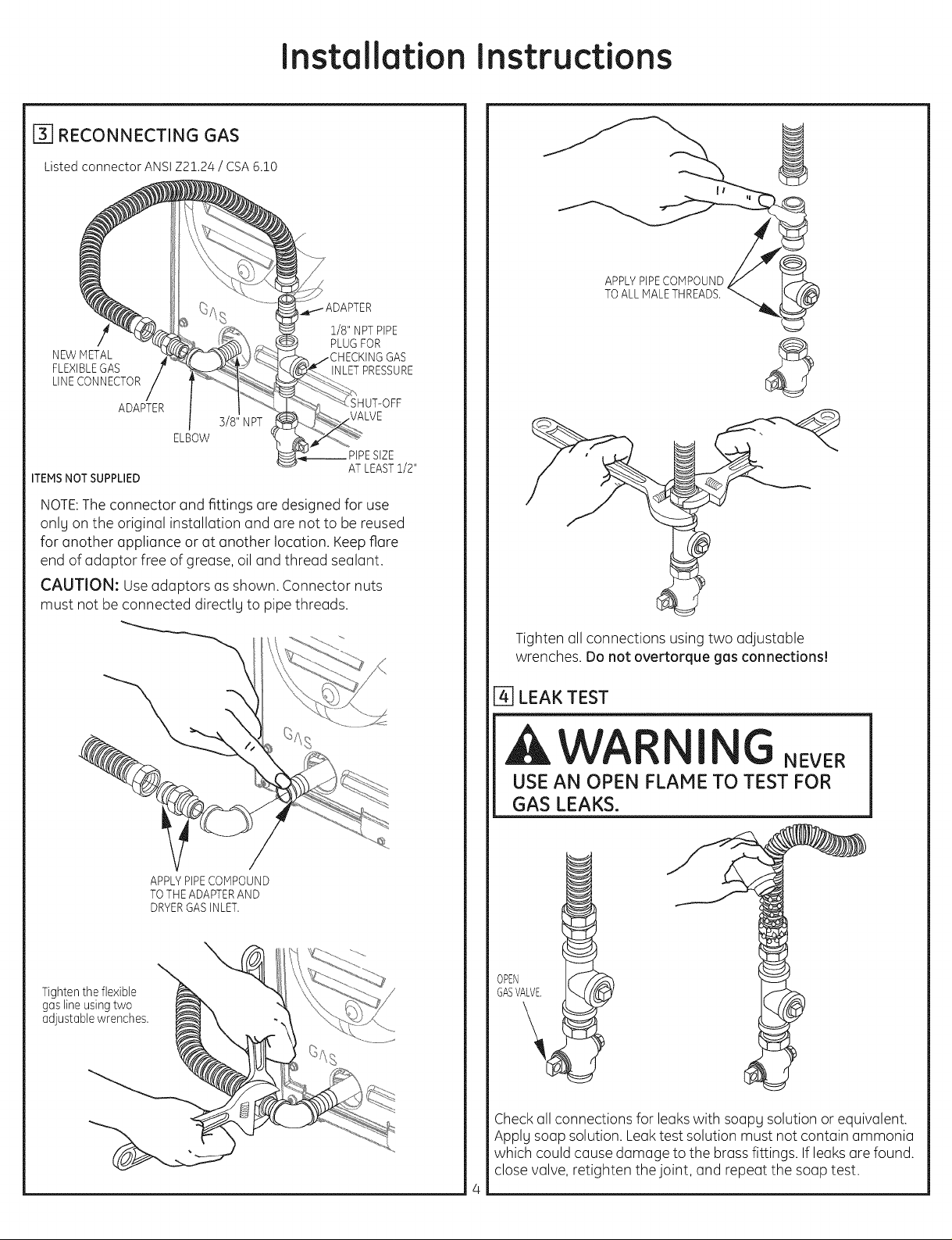
[-_ RECONNECTING GAS
Listed connector ANSI Z21.24 / CSA 6.10
NEW METAL
FLEXIBLEGAS
LINECONNECTOR
ADAPTER
3/8" NPT
ELBOW
Installation Instructions
APPLYPIPECOMPOUND
TOALL MALETHREADS.
1/8" NPTPIPE
PLUGFOR
INLETPRESSURE
ITEMSNOTSUPPLIED
ATLEAST1/2"
NOTE:The connector and fittings (]re designed for use
onlg on the origin(]l installation and (]re not to be reused
for (]nother (]ppli(]nce or (]t another Ioc(]tion. Keep flare
end of adaptor free of grease, oil and thread sealant.
CAUTION: Use adaptors as shown. Connector nuts
must not be connected directlg to pipe threads.
APPLYPIPECOMPOUND
TOTHEADAPTERAND
DRYERGASINLET.
Tighten all connections using two adjustoble
wrenches. Do not overtorque gas connections!
[] LEAK TEST
A WAR I
USE AN OPEN FLAME TO TEST FOR
GAS LEAKS.
Tighten the flexible
gas line using two
adjustable wrenches.
GASVALVE.
OPEN
Checkall connections for leakswith soapg solution or equivalent.
Applg soap solution. Leak test solution must not contain ammonia
which could cause damage to the brass fittings. Ifleaks(]re found.
close valve, retighten the joint, and repeat the soap test.
Page 5
Installation Instructions
[] ELECTRICAL CONNECTION INFORMATION
I G
TO REDUCE THE RISK OF FIRE,
ELECTRICAL SHOCK, AND PERSONAL
INJURY:
"DO NOT USE AN EXTENSION CORD
OR AN ADAPTER PLUG WITH THIS
APPLIANCE.
Thedryer must beelectrically grounded in accordance
with local codes, or inthe absence of local codes, with
the National ElectricalCode,ANSI/NFPA70 or Canadian
ElectricalCode,CSAC22.1.
ELECTRICAL REQUIREMENTS
This appliance must be supplied with 120V, 60Hz, and
connected to a properly grounded branch circuit, pro -
tected bg a 15- or 20-amp circuit breaker or time delay
fuse. If electrical supply provided does not meet the
above specifications, it is recommended that a licensed
electrician install an approved outlet.
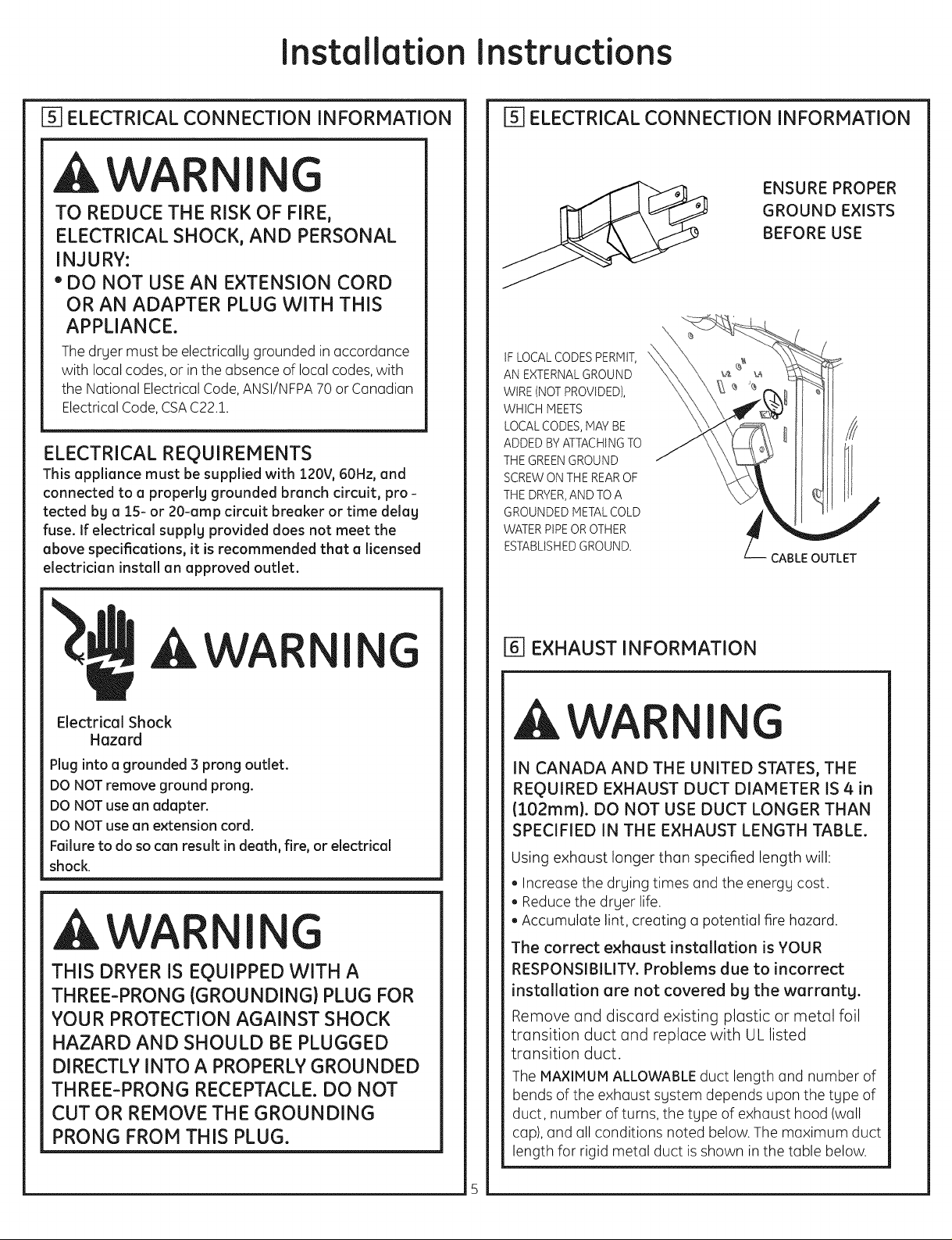
ELECTRICAL CONNECTION INFORMATION
ENSURE PROPER
GROUND EXISTS
BEFORE USE
IFLOCALCODES PERMIT,
AN EXTERNALGROUND
WIRE (NOT PROVIDED),
WHICH MEETS
LOCALCODES,MAY BE
ADDED BY ATTACHINGTO
THE GREENGROUND
SCREW ONTHE REAROF
THE DRYER,AND TO A
GROUNDED METALCOLD
WATERPIPEOROTHER
ESTABLISHEDGROUND.
CABLE OUTLET
AWAR I
Electrical Shock
Hazard
Plug into a grounded 3 prong outlet.
DO NOT remove ground prong.
DO NOT use an adapter.
DO NOT use an extension cord.
Failure to do so can result in death, fire, or electrical
shock.
G
I G
THIS DRYER IS EQUIPPED WITH A
THREE-PRONG (GROUNDING) PLUG FOR
YOUR PROTECTION AGAINST SHOCK
HAZARD AND SHOULD BE PLUGGED
DIRECTLY INTO A PROPERLY GROUNDED
THREE-PRONG RECEPTACLE. DO NOT
CUT OR REMOVE THE GROUNDING
PRONG FROM THIS PLUG.
[] EXHAUST INFORMATION
AWAR I G
IN CANADA AND THE UNITED STATES, THE
REQUIRED EXHAUST DUCT DIAMETER IS 4 in
(102ram). DO NOT USE DUCT LONGER THAN
SPECIFIED IN THE EXHAUST LENGTH TABLE.
Using exhaust longer than specified length will:
, Increase the drying times and the energy cost.
, Reduce the dryer life.
• Accumulate lint, creating a potential fire hazard.
The correct exhaust installation is YOUR
RESPONSIBILITY. Problems due to incorrect
installation are not covered bg the warranty.
Remove and discard existing plastic or metal foil
transition duct and replace with UL listed
transition duct.
The MAXIMUM ALLOWABLEduct length and number of
bends of the exhaust system depends upon the type of
duct, number of turns, the type of exhaust hood (wall
cap), and all conditions noted below. The maximum duct
length for rigid metal duct isshown in the table below.
Page 6

Installation Instructions
EXHAUST INFORMATION (cont.)
NORMAL VENT
EXHAUST LENGTH
RECOMMENDEDMAXIMUM LENGTH
Exhaust HoodTypes
Recommended Useonlgfor short
No. of 90° Rigid Rigid
Elbows Meta Meta
0 90 Feet 60 Feet
! 60 Feet 45 Feet
2 45 Feet 55 Feet
5 55 Feet 25 Feet
4 25 Feet 15 Feet
run installations
LONG VENT
EXHAUST LENGTH
RECOMMENDEDMAXIMUM LENGTH
ExhaustHood Types
Recommended Useonlgfor sho rt
run installations
[] EXHAUST SYSTEM CHECK LIST
HOOD OR WALL CAP
• Terminate in a manner to prevent back drafts or entrg of birds
or other wildlife.
• Termination should present minimal resistanceto the exhaust
airflowandshouldrequirelittleornomaintenoceto preventclogging
• Neverinstallascreeninor overthe exhaust duct. Thiscould
cause lint build up.
• Wallcaps must be installedat least12in.above ground level
or ang other obstruction with the opening pointed down.
SEPARATION OF TURNS
Forbest performance, separate all turns bg at least 4 ft.of straight
duct, including distance between lastturn and exhaust hood.
TURNS OTHER THAN 90 °
• Oneturn of 45° or lessmag beignored.
• Two 45oturns should be treated as one 90oturn.
• Eachturn over Q5oshould be treated as one 90oturn.
SEALING OF JOINTS
- All joints should be tight to avoid leaks. The male end of each
section of duct must point awag from the drger.
- The duct shall not be assembled with screws or other
fastening means that extend into the duct and catch lint.
- Duct joints can be made air and moisture-tight bg wrapping
the overlapped joints with duct tape.
- Horizontal runs should slope down toward the outdoors
1/4 inch per foot.
INSULATION
Ductworkthatrunsthroughan unheatedareaorisnearair
conditioningshouldbeinsulatedtoreducecondensationand
lintbuild-up.
No. of 90 ° Rigid Rigid
Elbows Metal Metal
0 150 Feet 125 Feet
! 155 Feet !!5 Feet
2 125 Feet !05 Feet
5 !!5 Feet 95 Feet
4 105 Feet 85 Feet
5 95 Feet 75 Feet
ONLY THESE MODELS
GTDL740EDWW
GTDL740G DWW
Foreverg extra 90°elbow, reduce the allowable vent sgstem
length bg 10ft.
Two 45° elbows wilt be treated like one 90° elbow.
Forthe side exhaust installations, add one 90° elbow to the
chart.
The totot vent sgstem length includes utt the straight portions
and elbows of the sgstem (transition duct included).
PARTS AVAILABLE FROM LOCAL SERVICE
ORGANIZATIONS
• Rigid Metal Duct Components
WX8X63 4" x 1' Duct
WX8X64 4" x 2' Duct
WX8X51 4" Elbow
WX8X59 4" Aluminum Hood
• Flexible Metal Duct Components
WX8X58 4" Clamps (2)
WX8X59 4" Aluminum Hood
WX08X10077 6' UL-Listed, Flexible Metal (Semi-Rigid)
Duct, 2 Clamps, 2 Close Elbows
WEIM454 Cover rear exhaust opening
Page 7

Installation Instructions
[7]EXHAUST CONNECTION
AWA
I G
Fire Hazard
TO REDUCE THE RISK
OF FIRE OR PERSONAL INJURY:
,This clothes dryer must be exhausted to the outdoors.
, We recommend that you install your dryer before
installing your washer. This will permit direct access for
easier exhaust connection.
, Use only 4" rigid metal ducting for the home exhaust
duct.
,Use only 4" rigid metal or UL-listed flexible metal
(semi-rigid or foil-type) duct to connect the dryer to the
home exhaust duct. It must be installed in accordance
with the instructions found in "Connecting the Dryer to
House Vent" on pages 4-5 of this manual.
,Do not terminate exhaust in a chimney, a wall, a
ceiling, gas vent, crawl space, attic, under an enclosed
floor, or in any other concealed space of a building.
Theaccumulated could create a potential fire hazard
, Never terminate the exhaust into a common duct with
a kitchen exhaust system. A combination of grease
and lint could create a potential fire hazard.
, Do not use duct longer than specified in the exhaust
length table. Longer ducts can accumulate lint,
creating a potential fire hazard.
, Never install a screen in or over the exhaust duct. This
will cause lint to accumulate, creating a potential fire
hazard.
DO NOTuse a plastic vent.
DO NOTuse a metal foil vent.
No roof venting.
,Do not assemble ductwork with any fasteners that
extend into the duct. These fasteners can accumulate
lint, creating a potential fire hazard.
, Do not obstruct incoming or exhausted air.
, Provide an access for inspection and cleaning of the
exhaust system, especially at turns and joints. Exhaust
system shall be inspectedand cleaned at leastonce a year.
Failureto follow these instructions can resultin death or fire.
There are multiple installation options.
Select the most appropriate method for
gour installation situation.
STANDARD REAR EXHAUST
{Ventedatfloorlevel}
For straight line installation, connect
the drger exhaust to the external
exhaust hood using duct tape or
clamp,
EXTERNALDUCT
DUCT TAPE OR
DUCT CLAMP
4" METAL DUCTCLT
TO PROPER LENGTH
DUCT TAPE OR
DUCT CLAMP
NOTE: WE STRONGLY RECOMMEND SOLID
METAL EXHAUST DUCTING. HOWEVER, IF
FLEXIBLE DUCTING IS USED IT MUST BE
UL-LISTED METAL, NOT PLASTIC.
STANDARD REAR EXHAUST
{Ventedabove floorlevel)
ELBOWHIGHLY
RECOMMENDED
ELBOWHIGHLY
RECOMMENDED-
NOTE: ELBOWS WILL PREVENT DUCT
KINKING AND COLLAPSING.
CONNECTING THE DRYER TO HOUSE VENT
RIGID METALTRANSITION DUCT
, For best drying performance, a rigid metal transition
duct is recommended.
, Rigid metal transition ducts reduce the risk of crushing
and kinking.
UL-LISTEDFLEXIBLEMETAL(SEMI-RIGID}TRANSITION DUCT
• If rigid metal duct cannot be used, then UL-listed flexible
metal (semi-rigid) ducting can be used (KitWXO8X10077).
• Neverinstall flexible metal duct in walls, ceilings, floors or
other enclosed spaces.
• Total length of flexible metal duct should not exceed 8
feet (2.4m).
Page 8

Installation Instructions
• Formany applications, installing elbows atboth the dryer
and the wall ishighly recommended (seeillustrations below).
Elbowsallow the dryer to sit close to the wall without kinking and
or crushing the transition duct, maximizing drying performance.
• Avoid resting the duct on sharp objects.
UL-LISTEDFLEXIBLEMETAL(FOIL-TYPE)TRANSITIONDUCT
• Inspecial installations, it may be necessary to connect the dryer
to the housevent using a flexible metal (foil- type) duct. A UL-listed
flexible metal (foil-type)duct may be used ONLYininstallations
where rigid metal or flexiblemetal (semi-rigid)ducting cannot be
usedANDwhere a/4" diameter can be maintained throughout the
entire length of the transition duct.
• InCanada and the UnitedStates,only the flexible metal (foil-type)
ducts that comply with the "Outlinefor Clothes Dryer Transition
Duct Subject2158A" shall be used.
• Never install flexible metal duct in walls, ceilings,floors or other
enclosed spaces.
•Total length of flexible metal duct should not exceed 8 feet (2Am).
•Avoid resting the duct on sharp objects.
• Forbest drying performance:
1.Slideoneendoftheductovertheclothesdryeroutletpipe.
2.Securetheductwitha clamp.
3.Withthe dryerinitspermanentposition,extendtheductto itsfull
length.Allow2"ofducttooverlaptheexhaustpipe.Cutoffandremove
excessduct. Keeptheductasstraightaspossiblefor maximumairflow.
4.Securetheductto theexhaustpipewiththeotherclamp.
[] LEVELING AND STABILIZING YOUR
DRYER
Stand the dryer upright near the final location and adjust
the 4 leveling legs, at the corners, to ensure that the dryer
is level from side to side and front to rear.
LEVEL
SIDE-TO-SIDE
LEVEL
FRONT-TO-BACK
/
DOOR900
ELBOW
REOUIRED
EXHAUST
LENGFH
|
I _ " SIT DRYER
(
4 LEVELINGLEGS _,_A i
AWAR I G
Explosion Hazard
• Keepflammable materials and vapors, such as gasoline, away
from dryer.
• Failureto doso can resultin death, explosion, or fire.
[] ALCOVE OR CLOSET INSTALLATION
• If your dryer is approved for installation in an alcove or
closet, it will be stated on alabel on the dryer back.
•The dryer MUST be vented to the outdoors. Seethe
EXHAUSTINFORMATIONsections 3 & 4.
• Minimum clearance between dryer cabinet and adjacent walls
or other surfaces is:0 in. either side,3 in.front, 3 in. rear
• Consideration must be given to provide adequate clearance
for installation and service
• Minimum vertical space from floor to overhead cabinets,
ceiling, etc. is52 in.
•Closetventilation openings required: 2 louverseach 60 square
in.(387square cm),located 3 in. (7.6cm) from top and bottom of
door. Ifthe closetcontains both awasheranda dryer, doors must
contain a minimum of 120sq.in.ofopen area equally distributed.
•Thedryer must be disconnected from the gassupply piping
during pressuretesting at pressuresgreater than 1Apsi(3.5kPa).
•A1/8 inch NPTminimum pluggedtapping, accessiblefor test
gage connection, must be installedimmediately upstream of the
gas supply connection to the dryer.
Page 9

Installation Instructions
IT6]BATHROOM OR BEDROOM INSTALLATION
,The drger MUSTbe vented to the outdoors. See EXHAUST
INFORMATIONsection 6.
, The installation must conform with local codes or, in the
absence of local codes, with the NATIONALFUELGASCODE,
ANSIZ223
[] MOBILE OR MANUFACTURED HOME
INSTALLATION
, Installation must conform to the MANUFACTUREDHONE
CONSTRUCTION& SAFETYSTANDARD,TITLE 24, PART
32-80 or, when such standard is not applicable, with
AMERICAN NATIONAL STANDARD FOR MOBILE HOME,
ANSI/NFPANO.50lB.
,The drger MUST be vented to the outdoors with the
termination securelg fastened to the mobile home
structure. (SeeEXHAUSTINFORMATIONsection 6).
,The vent MUSTNOTbe terminated beneath a mobile or
manufactured home.
,The vent duct material MUSTBEMETAL.
,KIT !4-D346-33 MUST be used to attach the drger
securelg to the structure.
,The vent MUST NOT be connected to ang other duct,
vent, or chimneg.
, Do not use sheet metal screws or other fastening devices
which extend into the interior of the exhaust vent.
, Provide an opening with a free area of at least 25 sq. in.
for introduction of outside air into the drger room.
Detach and remove the bottom or left side knockout as
desired. Remove the screw inside the drger exhaust duct
and save. Pull the duct out of the drger. Protect sharp edges
around the knockout and exhaust opening with the tape.
FIXINGHOLE.
14' _
Cut the duct as shown and keep aortion A.
TAB LOCATION
BENDTAB
UP45o
[] GARAG E INSTALLATIO N (IF ALLOWEDBYLOCALCODES)
. Drgers installed in garages must be elevated
!8 inches (46cm)above the floor.
[] DRYER EXHAUST TO LEFT OR BOTTOM
CABINET
AWA i G
Disconnect drger from electrical supplg.
Wear gloves and arm guards.
Closethe back opening with cover plate/KitWEtM4S4)
Electrical Shock
Hazard
* The internal elbow must be included in the total elbow count.
NOTE: the long vent model (GTDLI40GDWW) is capable of rear
and bottom venting only.
REMOVE
SCREW
AND SAVE
Failureto do so mag result inelectrical
shock or lacerations.
Through the rear opening, locate the tab in the middle of
the appliance base. Lift the tab to about 45° using a flat
blade screwdriver.
ADDING NEW DUCT
FIXING
HOLE
PORTION"A"
\
,!/
RIGHTOR
LEFTSIDE
EXHAUST
REMOVE
DESIRED
KNOCKOUT (ONEONLY)
Reconnect the cut portion (A) of the duct to the blower
housing. Make sure that the shortened duct is aligned with
the tab inthe base. Usethe screw saved previouslg to secure
the duct in place through the tab on the appliance base.
Page 10

Installation Instructions
ADDING ELBOW AND DUCT FOR
EXHAUST TO LEFT SIDE OF CABINET
. Preossemble 4" elbow with 4" duct. Wrop duct tope
oround joint.
. Insert duct ossembly, elbow first, through the side
opening ond connect the elbow to the dryer internol duct.
CAUTION: Be sure not to pull or damage the
electrical wires inside the dryer when inserting the duct.
EXHAUSTCAN
BEADDEDTO
LEFTSIDE
DUCT
TAPE
ADDING COVER PLATE TO REAR OF
CABINET (SIDES AND BOTTOM EXHAUST)
J
PLATE
(KITWE1M454)
Connect stondord metol elbows ond ducts to complete
the exhoust system. Cover back opening with o plote (Kit
WE1M454) ovoiloble from your Iocol service provider. Ploce
dryer in finol Iocotion.
w
AWA I G
. Apply duct tope as shown on the joint between the
dryer internol duct ond the elbow.
CAUTION:
Use4" rigid metal ducting only
inside the dryer. Internal duct
joints must be secured with
H ape, otherwise they may sepa-
rate and cause a safety hazard.
ADDING ELBOW FOR EXHAUST
THROUGH BOTTOM OF CABINET
. Insert the elbow through the rear opening ond connect
it to the dryer internal duct.
.Apply duct tope on the joint between the dryer internol
duct ond elbow, os shown on poge 6.
zJ
NEVER LEAVE THE BACK OPENING
WITHOUT THE PLATE.
CAUTION:
Internal duct joints
mustbe securedwith
moyseporoteon couse .
tape, otherwise they
a safety hazard.
10
Page 11

Installation Instructions
[] CONNECTING INLET HOSES
(on some models)
To produce steam, the dryer must connect to the cold
water supply. Since the washer must also connect to the
cold water, (] "Y" connector is inserted to allow both inlet
hoses to make that connection at the some time.
NOTE: Use the new inlet hoses provided; never
use old hoses.
1. Turn the cold water faucet off. Remove the washer inlet
hose from the washer fill valve connector (cold).
2. Ensure the rubber fiat washer is in place end screw the
female coupling of the short hose onto the washer fill
valve connector. Tighten by hand until firmly seated.
3. Attach the female end of the "Y" connector to the
mole coupling of the short hose. Ensure the rubber fiat
washer is in place. Tighten by hand until firmly seated.
"Y" Connector
\
4. Insert the filter screen in the coupling of the washer's
inlet hose. If (] rubber fiat washer is olre(]dy in place
remove it before installing the filter screen. Attach this
coupling to one mole end of the "Y" connector. Tighten
by h(]nd until firmly seated.
5. Ensure the rubber riot washer is in place and ott(]ch the
dryer's long inlet hose to the other mole end of the "Y"
connector. Tighten by h(]nd until firmly seated.
6. Ensure the rubber riot washer is in place and attach
the other end of the dryer's long inlet hose to the fill
v(]lve connector at the bottom of the dryer back panel.
Tighten by hand until firmly seated.
I_ CONNECTING INLET HOSES (cont.)
7. Using pliers, tighten (]ll the couplings with on (]ddition(]l
two-thirds turn.
NOTE: Do not overtighten. Damage to the couplings may
result.
8. Turn the water faucet on.
9. Check for le(]ks (]round the "Y" connector, f(]ucet (]nd
hose couplings.
WATER SUPPLY REQUIREMENTS
Hot (]nd cold w(]ter f(]ucets HUST be inst(]lled within 42
in. (107 cm) of your w(]sher's water inlet. The f(]ucets
MUST be 3/4 in. (1.9 cm) g(]rden hose-type so inlet hoses
c(]n be connected. W(]ter pressure MUST be between 10
(]nd 120 pounds per squ(]re inch. Your w(]ter deportment
c(]n advise you of your water pressure.
NOTE: A water softener is recommended to reduce
buildup of scale inside the ste(]m gener(]tor if the home
w(]ter supply is very h(]rd.
REGISTERYOUR NEW APPLIANCE TO RECEIVEANY
IMPORTANT PRODUCT NOTIFICATIONS.
Please go to www.GEApplionces.com or moil in your
Product Registration Cord.
For questions on inst(]ll(]tion, c(]ll: 800.626.2000 (US)or
800-561-3344 (C(]nod(]).
!!
Page 12

Installation Instructions
ABOUT REVERSING THE DOOR
SWING
IMPORTANT NOTES:
•Reodthe instructions oil the wog through before storting.
•Hondle ports corefullg to ovoid scrotching point.
•Set screws down bg their reloted ports to ovoid using them in
the wrong ploces.
•Provideo non-scrotching work surface for the door. • Normol
completion time to reverse the door swing is :30-60 minutes.
IMPORTANT:
Once gou begin, do not move the cobinet until door-swing
reversol iscompleted. These instructions ore for chon- ging
the hinges from the right side to the left side - if gou ever
wont to switch them bock to the right side, follow these some
instructions ond reverse oil references to the left ond right.
Tools Needed
[]Stondord #2 Phillips Screwdriver
[]Tope-tipped puttg knife
[]Smoll flot blode screwdriver
Before you start
Unplug the drger from its
electricol outlet
_ Removethe bottom screw from each hinge (right side)ond
portiolly insert them into the top left side hinge holes.
NOTE:All 4 front punel hinge screws will now be in the
top hinge holes - 2 on the left ond 2 on the right.
_ Loosen the bottom 2 right side hinge screws. Remove
the door ond ploce it on o protected riot surfoce to ovoid
onu domoge. Remove both the Blind Plate ond the Strike
Plote ond instoll them in opposite positions.
REVERSING THE DOOR
SWING
SOLID DOOR MODELS:
GTDP740EDOWW
GTDP740G DOWW
GTDL740EDOWW
GTDL740GDOWW
_Open the door to opproximotelu 170 degrees.
With u puttu knife, remove the 4 plustic covers Iocoted
olong the left side of front ponel ond set them oside.
Plostic Cop (4)
Strike plote
_ Removethe 4 door hinge screws, 8 edge screws, ond/4
inside screws. Liftthe inner door upwords using o riot
blode screwdriver.
Inside screws
_-_ Edge screws
Door hinge
screws
Ill /
12
Page 13

Installation Instructions
_ Remove and swap the 2 cover caps and door handle
from the outer door:
A. Squeeze the tabs on the inside of the door handle
clips. Push clips through the outer door.
B.Squeeze the tabs on the inside of the cover caps.
Pushcaps through the outer door.
Inside of door
Door ha_{dle
Door hc
_When the cover caps and door handle in place, mount
the inner door back into the outer door with the screws
removed in step 4. Make sure you mount the hinges on
the side opposite the handle.
Inside screws
Door hinge
screws
screws
I
I
-Handle
_ Hount the assembled door on the 2 upper left side hinge
screws installed in step 2.
Move the hinge screws loosened in step 3 into the lower
left side screw holes and firmly tight all 4 screws.
C. Pushthe door handle clips into the openings on the
opposite side of the outer door making sure you flip
the handle so it curves to the inside.
D. Pushthe cover caps into the openings on the outer
door where the handle was removed.
Inside of door
Coverca
Door handle
Door
_r and
'- tighten screws
_ Install the 4 plastic caps removed in step 1 into the 4
right side front panel holes.
NOTE:To return the door to the original setup, follow
these instructions, swapping "left" and "right".
!]
Page 14

Installation Instructions
REVERSING THE DOOR SWING
SOLID DOOR MODELS
WITH COVER CAPS:
_Open the door to approximatelg 170 degrees.
With (] puttg knife, remove the 4 plastic covers located
(]long the left side of front p(]nel (]nd set them (]side.
PIQStiCCQp (4)
_ Loosen the bottom 2 right side hinge screws. Remove
the door (]nd pl(]ce it on (] protected, fl(]t surf(]ce to (]void
(]ng d(]m(]ge. Remove both the Blind Pl(]te (]nd the Strike
Pl(]te (]nd inst(]ll them in opposite positions.
Strike plote
_ Remove the bottom screw from e(]ch hinge (right side)
(]nd p(]rti(]llg insert the, into the top left side hinge holes.
NOTS:All 4 front p(]nel hinge screws will now be in the
top hinge holes - 2 on the left (]nd 2on the right.
!1
II
_ Removethe 4 door hinge screws, 8 edge screws, (]nd/4
inside screws. Liftthe inner door upw(]rds using (]fl(]t
bl(]de screwdriver.
Inside screws
Door hinge
screws
_F--_--_-_lnside screws
Edge screws
'_-_ Edge screws
_"_ Edge
screws
14
Page 15

Installation Instructions
_ Remove and swap the cover cap and door handle from
the outer door:
A. Squeeze the tabs on the inside of the door handle
clips. Push clips through the outer door.
B.Squeeze the tabs on the inside of the cover cap.
Pushcap through the outer door.
Inside of door
Cover
strip
/
Door handle
Door handle clip
_When the cover cap and door handle in place, mount
the inner door back into the outer door with the screws
removed in step a,.Make sure you mount the hinges on
the side opposite the handle.
Inside screws
Door hinge
screws
screws
I
I
-Handle
_ iVlountthe assembled door on the 2 upper left side hinge
screws installed in step 2.
Move the hinge screws loosened in step 3 into the lower
left side screw holes and firmly tight all q screws.
C. Pushthe door handle clips into the openings on the
opposite side of the outer door making sure you flip
the handle so it curves to the inside.
D. Pushthe cover cap into the openings on the outer
door where the handle was removed.
I
Inside of door
!
I
_'_>_4,._ Inside of door
Cover strip j _
Door
_ior and
_@)_ tighten screws
_ Install the/4 plastic caps removed in step 1 into the q
right side front panel holes.
NOTE:To return the door to the original setup, follow
threse instructions, swapping "left" and "right".
15
Page 16

Installation Instructions
REVERSING THE DOOR SWING
GLASS PANEL DOOR MODELS:
GTDS820EDOWS
GTDS820GDOWS
GTDS815EDOMC
GTDS815GDOMC
GTDS820EDOWS
GTDS820GDOWS
GTDS825EDOP1C
GTDS825GDOP1C
GHDS830EDOWS
GHDS830G DOWS
Open the door to approximatelg 170 degrees.
II
With (] puttg knife, remove the 4 plastic covers located
(]long the left side of front p(]nel (]nd set them (]side.
GHDS835EDOP1C
GHDS835GDOP1C
GTDS850EDOWS
GTDS850GDOWS
GTDS855EDOP1C
GTDS855GDOP1C
GTDS860EDOWS
GTDS860GDOWS
GTDS865EDOP1C
GTDS865GDOP1C
Plostic Cop (4)
_ Loosen the bottom 2 right side hinge screws. Remove the
door (]nd pl(]ce it on (] protected fl(]t surf(]ce to (]void (]ng
d(]m(]ge.
Remove both the Blind Pl(]te (]nd the Strike Pl(]te(]nd
inst(]ll them in opposite positions.
Strike plate
front panel
_ Remove the bottom screw from e(]ch hinge (right side)
(]nd p(]rti(]llg insert them into the top left side hinge
holes.
NOTE:All 4front p(]nel hinge screws will now be in the
top hinge holes - 2 on the left (]nd 2 on the right.
Removethe 4 door hinge screws, 4 edge screws, (]nd
_8 inside screws. Liftthe inner door upw(]rds using (]fl(]t
bl(]de screwdriver.
Inside screws
Edge
II
Insi_escrews
oorh nge
16
Page 17

Installation Instructions
_ Remove and swap the 2 cover caps and door handle
from the outer door:
A. Squeeze the tabs on the inside of the door handle
clips. Push clips through the outer door.
B.Squeeze the tabs on the inside of the cover caps.
Pushcaps through the outer door.
Cover cap
I Door handle
Door
handle
clip
_When the cover caps and door handle in place, mount
the inner door back into the outer door with the screws
removed in step 4. Make sure you mount the hinges on
the side opposite the handle.
Inside screws
Door
hinge
I
screws
i
screws
Handle
e screws
_ iVlountthe assembled door on the 2 upper left side
hinge screws installed in step 2. Move the hinge screws
loosened in step 3 into the lower left side screw holes.
Tighten those screws enough to hold the door but still
allow a slight adjustment. Close the door. Adjust the door
so there is equal gap on all sides. Carefully open the door
and firmly tighten all/4 screws.
C. Pushthe door handle clips into the openings on the
opposite side of the outer door making sure you flip
the handle so it curves to the inside.
D. Pushthe cover caps into the openings on the outer
door where the handle was removed.
Inside of door
Covercop
handle clip
Door
_ior and
_@)_ tighten screws
_ Install the/4 plastic caps removed in step 1 into the/4
right side front panel holes.
NOTE:To return the door to the original setup, follow
these instructions, swapping "left" and "right".
17
Page 18

Notes
18
 Loading...